EP4458342A1 - Multifunktionelle massagevorrichtung - Google Patents
Multifunktionelle massagevorrichtung Download PDFInfo
- Publication number
- EP4458342A1 EP4458342A1 EP22822261.8A EP22822261A EP4458342A1 EP 4458342 A1 EP4458342 A1 EP 4458342A1 EP 22822261 A EP22822261 A EP 22822261A EP 4458342 A1 EP4458342 A1 EP 4458342A1
- Authority
- EP
- European Patent Office
- Prior art keywords
- positioning tube
- drive mechanism
- housing
- massage
- movable
- Prior art date
- Legal status (The legal status is an assumption and is not a legal conclusion. Google has not performed a legal analysis and makes no representation as to the accuracy of the status listed.)
- Pending
Links
Images



Classifications
-
- A—HUMAN NECESSITIES
- A61—MEDICAL OR VETERINARY SCIENCE; HYGIENE
- A61H—PHYSICAL THERAPY APPARATUS, e.g. DEVICES FOR LOCATING OR STIMULATING REFLEX POINTS IN THE BODY; ARTIFICIAL RESPIRATION; MASSAGE; BATHING DEVICES FOR SPECIAL THERAPEUTIC OR HYGIENIC PURPOSES OR SPECIFIC PARTS OF THE BODY
- A61H23/00—Percussion or vibration massage, e.g. using supersonic vibration; Suction-vibration massage; Massage with moving diaphragms
- A61H23/006—Percussion or tapping massage
-
- A—HUMAN NECESSITIES
- A61—MEDICAL OR VETERINARY SCIENCE; HYGIENE
- A61H—PHYSICAL THERAPY APPARATUS, e.g. DEVICES FOR LOCATING OR STIMULATING REFLEX POINTS IN THE BODY; ARTIFICIAL RESPIRATION; MASSAGE; BATHING DEVICES FOR SPECIAL THERAPEUTIC OR HYGIENIC PURPOSES OR SPECIFIC PARTS OF THE BODY
- A61H23/00—Percussion or vibration massage, e.g. using supersonic vibration; Suction-vibration massage; Massage with moving diaphragms
- A61H23/02—Percussion or vibration massage, e.g. using supersonic vibration; Suction-vibration massage; Massage with moving diaphragms with electric or magnetic drive
-
- A—HUMAN NECESSITIES
- A61—MEDICAL OR VETERINARY SCIENCE; HYGIENE
- A61H—PHYSICAL THERAPY APPARATUS, e.g. DEVICES FOR LOCATING OR STIMULATING REFLEX POINTS IN THE BODY; ARTIFICIAL RESPIRATION; MASSAGE; BATHING DEVICES FOR SPECIAL THERAPEUTIC OR HYGIENIC PURPOSES OR SPECIFIC PARTS OF THE BODY
- A61H23/00—Percussion or vibration massage, e.g. using supersonic vibration; Suction-vibration massage; Massage with moving diaphragms
- A61H23/02—Percussion or vibration massage, e.g. using supersonic vibration; Suction-vibration massage; Massage with moving diaphragms with electric or magnetic drive
- A61H23/0218—Percussion or vibration massage, e.g. using supersonic vibration; Suction-vibration massage; Massage with moving diaphragms with electric or magnetic drive with alternating magnetic fields producing a translating or oscillating movement
-
- A—HUMAN NECESSITIES
- A61—MEDICAL OR VETERINARY SCIENCE; HYGIENE
- A61H—PHYSICAL THERAPY APPARATUS, e.g. DEVICES FOR LOCATING OR STIMULATING REFLEX POINTS IN THE BODY; ARTIFICIAL RESPIRATION; MASSAGE; BATHING DEVICES FOR SPECIAL THERAPEUTIC OR HYGIENIC PURPOSES OR SPECIFIC PARTS OF THE BODY
- A61H23/00—Percussion or vibration massage, e.g. using supersonic vibration; Suction-vibration massage; Massage with moving diaphragms
- A61H23/02—Percussion or vibration massage, e.g. using supersonic vibration; Suction-vibration massage; Massage with moving diaphragms with electric or magnetic drive
- A61H23/0254—Percussion or vibration massage, e.g. using supersonic vibration; Suction-vibration massage; Massage with moving diaphragms with electric or magnetic drive with rotary motor
-
- A—HUMAN NECESSITIES
- A61—MEDICAL OR VETERINARY SCIENCE; HYGIENE
- A61H—PHYSICAL THERAPY APPARATUS, e.g. DEVICES FOR LOCATING OR STIMULATING REFLEX POINTS IN THE BODY; ARTIFICIAL RESPIRATION; MASSAGE; BATHING DEVICES FOR SPECIAL THERAPEUTIC OR HYGIENIC PURPOSES OR SPECIFIC PARTS OF THE BODY
- A61H9/00—Pneumatic or hydraulic massage
- A61H9/005—Pneumatic massage
- A61H9/0057—Suction
-
- A—HUMAN NECESSITIES
- A61—MEDICAL OR VETERINARY SCIENCE; HYGIENE
- A61H—PHYSICAL THERAPY APPARATUS, e.g. DEVICES FOR LOCATING OR STIMULATING REFLEX POINTS IN THE BODY; ARTIFICIAL RESPIRATION; MASSAGE; BATHING DEVICES FOR SPECIAL THERAPEUTIC OR HYGIENIC PURPOSES OR SPECIFIC PARTS OF THE BODY
- A61H2201/00—Characteristics of apparatus not provided for in the preceding codes
- A61H2201/01—Constructive details
- A61H2201/0119—Support for the device
- A61H2201/0153—Support for the device hand-held
-
- A—HUMAN NECESSITIES
- A61—MEDICAL OR VETERINARY SCIENCE; HYGIENE
- A61H—PHYSICAL THERAPY APPARATUS, e.g. DEVICES FOR LOCATING OR STIMULATING REFLEX POINTS IN THE BODY; ARTIFICIAL RESPIRATION; MASSAGE; BATHING DEVICES FOR SPECIAL THERAPEUTIC OR HYGIENIC PURPOSES OR SPECIFIC PARTS OF THE BODY
- A61H2201/00—Characteristics of apparatus not provided for in the preceding codes
- A61H2201/01—Constructive details
- A61H2201/0192—Specific means for adjusting dimensions
-
- A—HUMAN NECESSITIES
- A61—MEDICAL OR VETERINARY SCIENCE; HYGIENE
- A61H—PHYSICAL THERAPY APPARATUS, e.g. DEVICES FOR LOCATING OR STIMULATING REFLEX POINTS IN THE BODY; ARTIFICIAL RESPIRATION; MASSAGE; BATHING DEVICES FOR SPECIAL THERAPEUTIC OR HYGIENIC PURPOSES OR SPECIFIC PARTS OF THE BODY
- A61H2201/00—Characteristics of apparatus not provided for in the preceding codes
- A61H2201/12—Driving means
- A61H2201/1207—Driving means with electric or magnetic drive
-
- A—HUMAN NECESSITIES
- A61—MEDICAL OR VETERINARY SCIENCE; HYGIENE
- A61H—PHYSICAL THERAPY APPARATUS, e.g. DEVICES FOR LOCATING OR STIMULATING REFLEX POINTS IN THE BODY; ARTIFICIAL RESPIRATION; MASSAGE; BATHING DEVICES FOR SPECIAL THERAPEUTIC OR HYGIENIC PURPOSES OR SPECIFIC PARTS OF THE BODY
- A61H2201/00—Characteristics of apparatus not provided for in the preceding codes
- A61H2201/12—Driving means
- A61H2201/1207—Driving means with electric or magnetic drive
- A61H2201/1215—Rotary drive
-
- A—HUMAN NECESSITIES
- A61—MEDICAL OR VETERINARY SCIENCE; HYGIENE
- A61H—PHYSICAL THERAPY APPARATUS, e.g. DEVICES FOR LOCATING OR STIMULATING REFLEX POINTS IN THE BODY; ARTIFICIAL RESPIRATION; MASSAGE; BATHING DEVICES FOR SPECIAL THERAPEUTIC OR HYGIENIC PURPOSES OR SPECIFIC PARTS OF THE BODY
- A61H2201/00—Characteristics of apparatus not provided for in the preceding codes
- A61H2201/12—Driving means
- A61H2201/1207—Driving means with electric or magnetic drive
- A61H2201/123—Linear drive
-
- A—HUMAN NECESSITIES
- A61—MEDICAL OR VETERINARY SCIENCE; HYGIENE
- A61H—PHYSICAL THERAPY APPARATUS, e.g. DEVICES FOR LOCATING OR STIMULATING REFLEX POINTS IN THE BODY; ARTIFICIAL RESPIRATION; MASSAGE; BATHING DEVICES FOR SPECIAL THERAPEUTIC OR HYGIENIC PURPOSES OR SPECIFIC PARTS OF THE BODY
- A61H2201/00—Characteristics of apparatus not provided for in the preceding codes
- A61H2201/14—Special force transmission means, i.e. between the driving means and the interface with the user
- A61H2201/1481—Special movement conversion means
- A61H2201/149—Special movement conversion means rotation-linear or vice versa
-
- A—HUMAN NECESSITIES
- A61—MEDICAL OR VETERINARY SCIENCE; HYGIENE
- A61H—PHYSICAL THERAPY APPARATUS, e.g. DEVICES FOR LOCATING OR STIMULATING REFLEX POINTS IN THE BODY; ARTIFICIAL RESPIRATION; MASSAGE; BATHING DEVICES FOR SPECIAL THERAPEUTIC OR HYGIENIC PURPOSES OR SPECIFIC PARTS OF THE BODY
- A61H2201/00—Characteristics of apparatus not provided for in the preceding codes
- A61H2201/16—Physical interface with patient
- A61H2201/1657—Movement of interface, i.e. force application means
- A61H2201/1664—Movement of interface, i.e. force application means linear
-
- A—HUMAN NECESSITIES
- A61—MEDICAL OR VETERINARY SCIENCE; HYGIENE
- A61H—PHYSICAL THERAPY APPARATUS, e.g. DEVICES FOR LOCATING OR STIMULATING REFLEX POINTS IN THE BODY; ARTIFICIAL RESPIRATION; MASSAGE; BATHING DEVICES FOR SPECIAL THERAPEUTIC OR HYGIENIC PURPOSES OR SPECIFIC PARTS OF THE BODY
- A61H2201/00—Characteristics of apparatus not provided for in the preceding codes
- A61H2201/16—Physical interface with patient
- A61H2201/1657—Movement of interface, i.e. force application means
- A61H2201/1664—Movement of interface, i.e. force application means linear
- A61H2201/1669—Movement of interface, i.e. force application means linear moving along the body in a reciprocating manner
-
- A—HUMAN NECESSITIES
- A61—MEDICAL OR VETERINARY SCIENCE; HYGIENE
- A61H—PHYSICAL THERAPY APPARATUS, e.g. DEVICES FOR LOCATING OR STIMULATING REFLEX POINTS IN THE BODY; ARTIFICIAL RESPIRATION; MASSAGE; BATHING DEVICES FOR SPECIAL THERAPEUTIC OR HYGIENIC PURPOSES OR SPECIFIC PARTS OF THE BODY
- A61H2201/00—Characteristics of apparatus not provided for in the preceding codes
- A61H2201/16—Physical interface with patient
- A61H2201/1657—Movement of interface, i.e. force application means
- A61H2201/1676—Pivoting
-
- A—HUMAN NECESSITIES
- A61—MEDICAL OR VETERINARY SCIENCE; HYGIENE
- A61H—PHYSICAL THERAPY APPARATUS, e.g. DEVICES FOR LOCATING OR STIMULATING REFLEX POINTS IN THE BODY; ARTIFICIAL RESPIRATION; MASSAGE; BATHING DEVICES FOR SPECIAL THERAPEUTIC OR HYGIENIC PURPOSES OR SPECIFIC PARTS OF THE BODY
- A61H2209/00—Devices for avoiding blood stagnation, e.g. Deep Vein Thrombosis [DVT] devices
-
- A—HUMAN NECESSITIES
- A61—MEDICAL OR VETERINARY SCIENCE; HYGIENE
- A61H—PHYSICAL THERAPY APPARATUS, e.g. DEVICES FOR LOCATING OR STIMULATING REFLEX POINTS IN THE BODY; ARTIFICIAL RESPIRATION; MASSAGE; BATHING DEVICES FOR SPECIAL THERAPEUTIC OR HYGIENIC PURPOSES OR SPECIFIC PARTS OF THE BODY
- A61H9/00—Pneumatic or hydraulic massage
- A61H9/0007—Pulsating
Definitions
- the present disclosure relates to the technical field of massage devices, and in particular, relates to a multifunctional massage device.
- An object of the present disclosure is to provide a multifunctional massage device to solve the technical problem that the conventional massage device has a poor massage effect and experience.
- a multifunctional massage device includes:
- the massage portion includes a fixed circumferential wall, a movable wall, and a connection circumferential wall, wherein the connection circumferential wall is disposed between the fixed circumferential wall and the movable wall, and the fixed circumferential wall is connected to the telescope mechanism; and the multifunctional massage device further includes a connection rod, wherein one end of the connection rod is connected to the movable wall, and the other end of the connection rod is connected to the drive mechanism, and the drive mechanism is configured to control, by the connection rod, the movable wall to reciprocate.
- the telescope mechanism includes a telescope assembly and a movable portion, wherein the movable portion is slidably disposed on the telescope assembly and is fixedly connected to the drive mechanism, the telescope assembly is provided with a first limiting portion and a second limiting portion, and the telescope assembly is configured to drive the movable portion to slide; or
- the telescope assembly includes a first positioning tube and a second positioning tube, wherein an outer diameter of the first positioning tube is less than an inner diameter of the second positioning tube, the first positioning tube is mounted in the second positioning tube, the second positioning tube is clockwise or counterclockwise rotatable relative to the first positioning tube, the first limiting portion is disposed at one end of the first positioning tube, and the second limiting portion is disposed at the other end of the first positioning tube; wherein a first chute is arranged in the first positioning tube, the first chute being disposed between the first limiting portion and the second limiting portion, and a guide groove or a guide groove ring having a guide groove is arranged in the second positioning tube, wherein the movable portion is inserted into the first chute and is slidably mounted in the guide groove, and the movable portion is in a circular-shaft shape.
- the first chute is axially disposed along the first positioning tube, a length of the first chute is less than or equal to a spacing between the first limiting portion and the second limiting portion, a first corner that is circumferentially disposed along the first positioning tube is defined at an end, close to the first limiting portion, of the first chute, and a second corner that is circumferentially disposed along the first positioning tube is defined at an end, close to the second limiting portion, of the first chute, wherein one of the first corner and the second corner is clockwise circumferentially disposed along the first positioning tube, and the other of the first corner and the second corner is counterclockwise circumferentially disposed along the first positioning tube;
- the number of the first chutes is two and an opening extending to the first limiting portion is arranged in at least one of the two first chutes
- the number of the movable portions is two and the two movable portions are symmetrically arranged
- the number of the guide grooves is two and the two guide grooves are symmetrically arranged
- the guide groove is a spiral guide groove which spirally extends from one end of the second positioning tube to the other end of the second positioning tube
- the first positioning tube is made of an elastic material
- a diameter of the movable portion is less than a width of the first chute
- a length of the movable portion is greater than a thickness of a wall thickness of the first positioning tube
- the length of the movable portion is less than or equal to a sum of a wall thickness of the first positioning tube and a depth of the guide groove.
- first limiting portion and the second limiting portion are disposed on an outer periphery of the first positioning tube, and are radially protruded from the first positioning tube; an annular limiting groove engageable with the first limiting portion of the first positioning tube is disposed on an inner wall at one end of the second positioning tube, and in the case that the first positioning tube is mounted in the second positioning tube, the first limiting portion is nested into the annular limiting groove, and the second limiting portion is abutted against one end, facing away from the annular limiting groove, of the second positioning tube; and a length of the second positioning tube is less than a length of the first positioning tube, and in the case that the first positioning tube is mounted in the second positioning tube, the second limiting portion of the first positioning tube is exposed from the second positioning tube.
- the fixed circumferential wall is cladding connected to one end of the second positioning tube, radial snaps are disposed on an outer periphery at one end, connected to the fixed circumferential wall, of the second positioning tube, the radial snaps being connected to define an annular snap;
- the drive mechanism is an electromagnetic drive mechanism, the electromagnetic drive mechanism including a cylindrical bobbin, a coil element disposed on an outer periphery of the cylindrical bobbin, and a moving magnet mounted in an inner cavity of the cylindrical bobbin and reciprocating therein; wherein one end of the connection rod is directly or indirectly connected to the moving magnet, the moving magnet drives the connection rod to reciprocate to control the movable wall to reciprocate; and wherein the movable portion is formed by an end body extending from one end of the cylindrical bobbin or is a structure mounted at one end of the cylindrical bobbin; or
- the housing includes a gripping portion, a tail cover, and a top cover, the tail cover and the top cover being respectively disposed at two ends of the gripping portion, the top cover at least covering the massage portion; wherein an accommodation chamber is arranged in the gripping portion, the accommodation chamber being provided with a battery and a circuit control unit, the battery being electrically connected to the circuit control unit, the circuit control unit being electrically connected to the drive mechanism; and wherein the telescope mechanism is connected to one end, facing away from the tail cover, of the gripping portion, and the massage portion, the telescope mechanism, and the gripping portion are disposed in a same axis; or the housing includes an upper housing, a lower housing, and a silicone sleeve, the silicone sleeve being sleeved on the upper housing and the lower housing to mount the upper housing and the lower housing; wherein an accommodation chamber is defined by mounting the upper housing and the lower housing, the accommodation chamber being provided with a battery and a circuit control unit; and wherein the drive mechanism and the telescope mechanism
- the embodiments of the present disclosure mainly achieve the following beneficial effects:
- the massage portion is made to be in contact with the part to be massaged, and the drive mechanism controls, via the connection rod, the movable wall to reciprocate.
- the drive mechanism controls, via the connection rod, the movable wall to reciprocate, such that the movable wall is capable of carrying out tapping massage on the part to be massaged.
- the drive mechanism drives, via the connection rod, the movable wall to reciprocate to change the volume of the first chamber, such that a suction force is produced in the first chamber to carry out suction massage on the part to be massaged in the massaging recess.
- a multifunctional massage device includes:
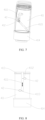
- the massage portion 2 is capable of being protruded from the housing 1 or being recessed to the housing 1.
- the telescope mechanism 4 drives the drive mechanism 3 to telescope in the housing 1 to drive the massage portion 2 connected to the drive mechanism 3 to telescope in the housing 1, such that the massage portion 2 transitions between being protruded from the housing 1 and being recessed to the housing 1, and the massage portion 2 is driven by the drive mechanism 3 to reciprocate.
- the massage portion 2 achieves two massage modes by transitioning between being protruded from the housing 1 and being recessed to the housing 1.
- the massage portion 2 is protruded from the housing 1, the massage portion 2 is made to be in contact with a part to be massaged, the drive mechanism 3 drives the massage portion 2 to reciprocate, and the massage portion 2 is capable of carrying out tapping massage on the part to be massaged.
- the massage portion 2 is recessed to the housing 1, a massaging recess is defined at one end, located on the massage portion 2, of the housing 1, the massaging recess is covered on the part to be massaged, and the drive mechanism 3 drives the massage portion 2 to reciprocate, such that the massaging recess produces a suction force to carry out suction massage on the part to be massaged in the massaging recess.
- the multifunctional massage device is capable of carrying out both tapping massage and suction massage, and relieving fatigue, stretching the skin or muscle, and achieving a health-care effect.
- the multifunctional massage device is capable of accurately massaging different parts of a human body, and improving comfort of massage and greatly enhancing the massage effect.
- the multifunctional massage device may quickly transition between tapping massage and suction massage, such that use convenience of the multifunctional massage is greatly improved.
- the telescope mechanism 4 includes a telescope assembly 41 and a movable portion 42.
- the movable portion 42 is slidably disposed on the telescope assembly 41 and is fixedly connected to the drive mechanism 3.
- the telescope assembly 41 is provided with a first limiting portion 413 and a second limiting portion 414.
- the telescope assembly 41 is configured to drive the movable portion 42 to slide, and control the drive mechanism 3 to move between the first limiting portion 413 and the second limiting portion 414.
- the position of the drive mechanism 3 may be manually adjusted by the telescope assembly 41.
- the telescope assembly 41 drives the movable portion 42 to slide on the telescope assembly 41, such that the drive mechanism 3 fixedly connected to the movable portion 42 telescopes in the housing 1.
- a stroke of the drive mechanism 3 is limited between the first limiting portion 413 and the second limiting portion 414, such that the drive mechanism 3 drives the massage portion 2 to transition between being protruded from the housing 1 and being recessed to the housing 1.
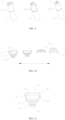
- the telescope assembly 41 includes a first positioning tube 411 and a second positioning tube 412.
- An outer diameter of the first positioning tube 411 is less than an inner diameter of the second positioning tube 412.
- the first positioning tube 411 is mounted in the second positioning tube 412.
- the second positioning tube 412 is clockwise or counterclockwise rotatable relative to the first positioning tube 411.
- the first limiting portion 413 is disposed at one end of the first positioning tube 411.
- the second limiting portion 414 is disposed at the other end of the first positioning tube 411. Two ends of the second positioning tube 412 are respectively connected to the first limiting portion 413 and the second limiting portion 414.
- a first chute 4111 is arranged in the first positioning tube 411.
- the first chute 4111 is disposed between the first limiting portion 413 and the second limiting portion 414.
- a guide groove 4121 or a guide groove ring having a guide groove 4121 is arranged in the second positioning tube 412.
- the movable portion 42 is inserted into the first chute 4111 and is slidably mounted in the guide groove 4121.
- the movable portion 42 is in a circular-shaft shape.
- the first chute 4111 is axially disposed along the first positioning tube 411 and has a specific length.
- the length of the first chute 4111 is less than or equal to a spacing between the first limiting portion 413 and the second limiting portion 414. Therefore, in the case that the second positioning tube 412 is clockwise or counterclockwise rotated relative to the first positioning tube 411, the movable portion 42 is driven to slide in both the first chute 4111 and the guide groove 4121, and is limited to sliding between the first limiting portion 413 and the second limiting portion 414. In this way, the stroke of the drive mechanism 3 is limited between the first limiting portion 413 and the second limiting portion 414.
- a first corner 4112 that is circumferentially disposed along the first positioning tube 411 is defined at an end, close to the first limiting portion 413, of the first chute 4111, and a second corner 4113 that is circumferentially disposed along the first positioning tube 411 is defined at an end, close to the second limiting portion 414, of the first chute 4111.
- One of the first corner 4112 and the second corner 4113 is clockwise circumferentially disposed along the first positioning tube 411, and the other of the first corner 4112 and the second corner 4113 is counterclockwise circumferentially disposed along the first positioning tube 411.
- first corner 4112 is clockwise circumferentially disposed along the first positioning tube 411
- second corner 4113 is counterclockwise circumferentially disposed along the first positioning tube 411, such that in the case that the second positioning tube 412 is clockwise or counterclockwise rotated relative to the first positioning tube 411, the movable portion 42 is capable of sliding in the first chute 4111 and sliding to the first corner 4112 or the second corner 4113.
- the drive mechanism 3 is disposed in the first positioning tube 411.
- the second positioning tube 412 is capable of counterclockwise or clockwise rotating relative to the first positioning tube 411 and driving the movable portion 42 to slide in both the first chute 4111 and the guide groove 4121 to drive the drive mechanism 3 to move in the first positioning tube 411.
- the second positioning tube 412 is capable of stopping rotating relative to the first positioning tube 411, and the drive mechanism 3 is fixed at a corresponding position of the first limiting portion 413 on the first positioning tube 411.
- the first positioning tube 411 is also capable of counterclockwise or clockwise rotating relative to the second positioning tube 412.
- description is given using the scenario where the second positioning tube 412 is rotated relative to the first positioning tube 411.
- the guide groove 4121 of the second positioning tube 412 drives the movable portion 42 to slide on the first chute 4111 towards the first corner 4112, to drive the drive mechanism 3 fixedly connected to the movable portion 42 to move in the first positioning tube 411.
- the movable portion 42 enters the first corner 4112
- the movable portion 42 is limited at the first corner 4112
- the second positioning tube 412 is capable of stopping rotating relative to the first positioning tube 411, that is, the second positioning tube 412 is incapable of counterclockwise rotating relative to the first positioning tube 411
- the second positioning tube 412 is only capable of clockwise rotating relative to the first positioning tube 411.
- the drive mechanism 3 is fixed at the corresponding position of the first limiting portion 413 on the first positioning tube 411, that is, the position of the movable portion 42 is limited via the first corner 4112, such that the position of the drive mechanism 3 in the first positioning tube 411 is limited.
- the second positioning tube 412 is capable of clockwise or counterclockwise rotating relative to the first positioning tube 411 and driving the movable portion 42 to slide in both the first chute 4111 and the guide groove 4121 to drive the drive mechanism 3 to move in the first positioning tube 411.
- the second positioning tube 412 is capable of stopping rotating relative to the first positioning tube 411, and the drive mechanism 3 is fixed at a corresponding position of the second limiting portion 414 on the first positioning tube 411.
- the guide groove 4121 of the second positioning tube 412 drives the movable portion 42 to slide on the first chute 4111 towards the second corner 4113, to drive the drive mechanism 3 fixedly connected to the movable portion 42 to move in the first positioning tube 411.
- the movable portion 42 enters the second corner 4113, the movable portion 42 is limited at the second corner 4113, the second positioning tube 412 is capable of stopping rotating relative to the first positioning tube 411, that is, the second positioning tube 412 is incapable of clockwise rotating relative to the first positioning tube 411, and the second positioning tube 412 is only capable of counterclockwise rotating relative to the first positioning tube 411.
- the drive mechanism 3 is fixed at the corresponding position of the second limiting portion 414 on the first positioning tube 411, that is, the position of the movable portion 42 is limited via the second corner 4113, such that the position of the drive mechanism 3 in the first positioning tube 411 is limited.
- the massage portion 2 is protruded from the housing 1. Since the massage portion 2 is connected to the drive mechanism 3, in the case that the second positioning tube 412 is counterclockwise rotated relative to the first positioning tube 411, the guide groove 4121 of the second positioning tube 412 drives the movable portion 42 to slide on the first chute 4111 towards the first corner 4112, such that the massage portion 2 connected to the drive mechanism 3 is driven to move along a direction of being protruded from the housing 1. In the case that the movable portion 42 enters the first corner 4112, the drive mechanism 3 is fixed at the corresponding position of the first limiting portion 413 on the first positioning tube 411, such that the massage portion 2 is protruded from the housing 1.
- the massage portion 2 is recessed to the housing 1. Since the massage portion 2 is connected to the drive mechanism 3, in the case that the second positioning tube 412 is clockwise rotated relative to the first positioning tube 411, the guide groove 4121 of the second positioning tube 412 drives the movable portion 42 to slide on the first chute 4111 towards the second corner 4113, such that the massage portion 2 connected to the drive mechanism 3 is driven to move along a direction of being recessed to the housing 1.
- the drive mechanism 3 is fixed at the corresponding position of the second limiting portion 414 on the first positioning tube 411, such that the massage portion 2 is recessed to the housing 1. Therefore, by relative rotations between the second positioning tube 412 and the first positioning tube 411, the massage portion 2 quickly transitions between being protruded from the housing 1 and being recessed to the housing 1. In this way, the massage device quickly transitions between tapping massage and suction massage, and use convenience of the massage device is greatly improved.
- the number of the first chutes 4111 is two.
- An opening extending to the first limiting portion 413 is arranged in at least one of the two first chutes 4111, such that the movable portion 42 is conveniently mounted in the first chute 4111 via the opening.
- the number of the movable portions 42 is two.
- the two movable portions 42 are symmetrically arranged.
- the number of the guide grooves 4121 is two.
- the two guide grooves 4121 are symmetrically arranged.
- the guide groove 4121 is a spiral guide groove which spirally extends from one end of the second positioning tube 412 to the other end of the second positioning tube 412. In the case that the second positioning tube 412 is rotated relative to the first positioning tube 411, the movable portion 42 slides, under driving by the spiral guide groove, in the first guide groove 4121.
- the first positioning tube 411 is made of an elastic material
- a diameter of the movable portion 42 is less than a width of the first chute 4111
- a length of the movable portion 42 is greater than a thickness of a wall thickness of the first positioning tube 411
- the length of the movable portion 42 is less than or equal to a sum of a wall thickness of the first positioning tube 411 and a depth of the guide groove 4121.
- the length of the movable portion 42 is equal to the sum of the wall thickness of the first positioning tube 411 and the depth of the guide groove 4121.
- the first limiting portion 413 and the second limiting portion 414 are disposed on an outer periphery of the first positioning tube 411, and are radially protruded from the first positioning tube 411.
- An annular limiting groove 4122 engageable with the first limiting portion 413 of the first positioning tube 411 is disposed on an inner wall at one end of the second positioning tube 412.
- the first limiting portion 413 is nested into the annular limiting groove 4122
- the second limiting portion 414 is abutted against one end, facing away from the annular limiting groove 4122, of the second positioning tube 412.
- a length of the second positioning tube 412 is less than a length of the first positioning tube 411.
- the second limiting portion 414 of the first positioning tube 411 is exposed from the second positioning tube 412.
- the massage portion 2 includes a fixed circumferential wall 21, a movable wall 22, and a connection circumferential wall 23.
- the connection circumferential wall 23 is disposed between the fixed circumferential wall 21 and the movable wall 22, and the fixed circumferential wall 21 is connected to the telescope mechanism 4.
- the multifunctional massage device further includes a connection rod 5.
- One end of the connection rod 5 is connected to the movable wall 22, and the other end of the connection rod 5 is connected to the drive mechanism 3.
- the drive mechanism 3 is configured to control, by the connection rod 5, the movable wall 22 to reciprocate.
- connection hole 221 is arranged in the movable wall 22.
- the connection hole 221 is configured to allow the connection rod 5 to be inserted therein.
- An insertion end of the connection rod 5 is engageable with the connection hole 221.
- the massage portion 2 is recessed to the housing 1
- at least one first chamber 24 is defined in the massage portion 2
- the fixed circumferential wall 21 defines an opening 25 of the first chamber
- the movable wall 22 defines a bottom of the first chamber
- the connection circumferential wall 23 defines a chamber wall of the first chamber 24 between the fixed circumferential wall 21 and the movable wall 22.
- the opening 25 of the first chamber 24 is greater than the bottom of the first chamber 24.
- a massaging recess is defined at one end, located at the massage portion 2, of the housing 1.
- the massaging recess is covered on the part to be massaged, the drive mechanism 3 drives, via the connection rod 5, the movable wall 22 to reciprocate to change the volume of the first chamber 24, such that a suction force is produced in the first chamber 24 to carry out suction massage on the part to be massaged in the massaging recess.
- connection rod 5 is inserted into the connection hole 221 of the movable wall 22.
- the connection wall drives the movable wall 22 to be protruded from the housing 1, and the massage portion 2 is in contact with the part to be massaged.
- the drive mechanism 3 controls, via the connection rod 5, the movable wall 22 to reciprocate, and the movable wall 22 is capable of carrying out tapping massage on the part to be massaged.
- the fixed circumferential wall 21 is cladding connected to one end of the second positioning tube 412, and radial snaps are disposed on an outer periphery at one end, connected to the fixed circumferential wall 21, of the second positioning tube 412.
- the radial snaps are connected to define an annular snap 4123.
- Snaps facing oppositely from the opening 25 are disposed on an outer periphery of the opening 25, where the fixed circumferential wall 21 is disposed, of the first chamber 24.
- the snaps are connected to define an annular snap fastener 211.
- the annular snap fastener 211 has an inwardly radial chamfer, and the annular snap 4123 is tightly inlaid into the radial chamfer of the annular snap fastener 211.
- An extension portion is disposed on the fixed circumferential wall 21 in a direction facing towards the opening 25 of the first chamber 24, and an extended circumferential wall 26 is defined.
- the massage portion 2 is made to be in contact with the part to be massaged, and the drive mechanism 3 controls, via the connection rod 5, the movable wall 22 to reciprocate. In this way, tapping massage or suction massage is carried out on the part to be massaged.
- the drive mechanism 3 controls, via the connection rod 5, the movable wall 22 to reciprocate, and the movable wall 22 is capable of carrying out tapping massage on the part to be massaged.
- the drive mechanism 3 drives, via the connection rod 5, the movable wall 22 to reciprocate to change the volume of the first chamber 24, such that suction force is produced in the first chamber 24 to carry out suction massage on the part to be massaged.
- Accurate massage may be carried out on a small region of the human body, or massage may be carried out on some protruded parts of the human body.
- the drive mechanism 3 is an electromagnetic drive mechanism 31.
- the electromagnetic drive mechanism 31 includes a cylindrical bobbin 311, a coil element 312 disposed on an outer periphery of the cylindrical bobbin 311, and a moving magnet 313 mounted in the cylindrical bobbin 311 and reciprocating therein.
- the electromagnetic drive mechanism 31 further includes a magnet limiting ring 17 and a magnet ring 18.
- the magnet limiting ring 17 is disposed at a bottom of the cylindrical bobbin 311.
- the number of the magnet rings 18 is two, and the two magnet rings 18 are respectively mounted at a top of the cylindrical bobbin 311 and the magnet limiting ring 17 at the bottom of the cylindrical bobbin 311.
- connection rod 5 is directly or indirectly connected to the moving magnet 313.
- the connection rod 5 is indirectly connected to the moving magnet 313 via a connection rod fixing ring 19, or the connection rod 5 is directly fixedly connected to the moving magnet 313.
- the moving magnet 313 drives the connection rod 5 to reciprocate to control the movable wall 22 to reciprocate.
- the movable portion 42 is formed by an end body extending from one end of the cylindrical bobbin 311 or is a structure mounted at one end of the cylindrical bobbin 311.
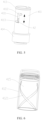
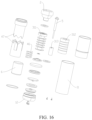
- the housing 1 is in a lipstick tube shape, such that the multifunctional massage device has good portability.
- the housing 1 includes a gripping portion 11, a tail cover 12, and a top cover 13.
- the tail cover 12 and the top cover 13 are respectively disposed at two ends of the gripping portion 11.
- the top cover 13 at least covers the massage portion 2.
- An accommodation chamber is arranged in the gripping portion 11.
- the accommodation chamber is provided with a battery 6 and a circuit control unit 7.
- the battery 6 is electrically connected to the circuit control unit 7.
- the circuit control unit 7 is electrically connected to the drive mechanism 3.
- the telescope mechanism 4 is connected to one end, facing away from the tail cover 12, of the gripping portion 11.
- the massage portion 2, the telescope mechanism 4, and the gripping portion 11 are disposed in a same axis.
- the multifunctional massage device further includes a button 8, charging nails 9, and a waterproof ring 10.
- the button 8 and the charging nails 9 are disposed on the tail cover 12.
- the button 8 is configured to turn on or turn off the multifunctional massage device.
- the charging nails 9 are configured to charge the multifunctional massage device.
- the waterproof ring 10 is disposed between the tail cover 12 and the gripping portion 11 to seal a gap between the tail cover 12 and the gripping portion 11.
- the circuit control unit 7 includes a PCBA 71, a PCBA cover 72, a silicone base 73, and a silicone positioning ring 74.
- the PCBA 71 is disposed in the PCBA cover 72.
- One face of the silicone base 73 is connected to the tail cover 12, and the other face of the silicone base is connected to the silicone positioning ring 74.
- the silicone positioning ring 74 is connected to the PCBA 71.
- the massage portion 2 is capable of being protruded from the housing 1 or being recessed to the housing 1.
- the second positioning tube 412 is counterclockwise rotated relative to the first positioning tube 411, and the guide groove 4121 of the second positioning tube 412 drives the movable portion 42 to slide on the first chute 4111 towards the first corner 4112, such that the drive mechanism 3 fixedly connected to the movable portion 42 is driven to slide in the first positioning tube 411.
- the movable portion 42 enters the first corner 4112, the movable portion 42 is limited at the first corner 4112, and the second positioning tube 412 stops rotating relative to the first positioning tube 411.
- the drive mechanism 3 Since the movable portion 42 is limited at the first corner 4112, the drive mechanism 3 is fixed at the corresponding position of the first limiting portion 413 on the first positioning tube 411. In this case, the massage portion 2 is protruded from the housing 1.
- the electromagnetic drive mechanism 31 controls, via the connection rod 5, the movable wall 22 to reciprocate, such that the movable wall 22 carries out tapping massage on the part to be massaged.
- the second positioning tube 412 is clockwise rotated relative to the first positioning tube 411, and the guide groove 4121 of the second positioning tube 412 drives the movable portion 42 to slide on the first chute 4111 towards the second corner 4113, such that the drive mechanism 3 fixedly connected to the movable portion 42 is driven to slide in the first positioning tube 411.
- the movable portion 42 enters the second corner 4113, the movable portion 42 is limited at the second corner 4113, and the second positioning tube 412 stops rotating relative to the first positioning tube 411. Since the movable portion 42 is limited at the second corner 4113, the drive mechanism 3 is fixed at the corresponding position of the second limiting portion 414 on the first positioning tube 411. In this case, the massage portion 2 is protruded from the housing 1.
- the electromagnetic drive mechanism 31 controls, via the connection rod 5, the movable wall 22 to reciprocate to change the volume of the first chamber 24, such that a suction force is produced in the first chamber 24 to carry out suction massage on the part to be massaged in the massaging recess.
- the massage portion 2 quickly transitions between being protruded from the housing 1 and being recessed to the housing 1.
- the massage device quickly transitions between tapping massage and suction massage, and use convenience of the massage device is greatly improved.
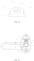
- the housing 1 has a T-shaped cross section in this embodiment.
- the housing 1 includes an upper housing 14, a lower housing 15, and a silicone sleeve 16.
- the silicone sleeve 16 is sleeved on the upper housing 14 and the lower housing 15 to mount the upper housing 14 and the lower housing 15.
- An accommodation chamber is defined by mounting the upper housing 14 and the lower housing 15.
- the drive mechanism 3, the telescope mechanism 4, the battery 6, and the like are mounted in the accommodation chamber.
- the battery 6 is electrically connected to the circuit control unit 7.
- the circuit control unit 7 is electrically connected to the drive mechanism 3.
- the telescope mechanism 4 includes a motor 43 and a lead screw 44.
- the motor 43 is connected to the lead screw 44.
- the drive mechanism 3 is connected to a nut seat on the lead screw 44.
- the motor 43 is connected to the circuit control unit 7.
- the telescope mechanism 4 further includes a synchronous wheel 48 and a synchronous belt 49 sleeved on the synchronous wheel 48.
- the motor 43 drives the synchronous wheel 48 to rotate to drive the synchronous belt 49 to rotate, such that the lead screw 44 is driven to move.
- the telescope mechanism 4 further includes a slidable support 45 and a movable portion 42.
- the slidable support 45 is disposed in the housing 1.
- a second chute 451 is arranged in the slidable support 45.
- the movable portion 42 is slidably disposed in the second chute 451 and is fixedly connected to the drive mechanism 3.
- the motor 43 drives the lead screw 44 to move, the nut seat on the lead screw 44 drives the drive mechanism 3 to move, and the drive mechanism 3 slides on the second chute 451 via the movable portion 42.
- the drive mechanism 3 telescopes in the housing 1, such that the drive mechanism 3 drives the massage portion 2 transitions between being protruded from the housing 1 and being recessed to the housing 1.
- the telescope mechanism is a ball-pen manual press mechanism.
- the manual press mechanism includes a spring 46 and a lock catch 47.
- the lock catch 47 is connected to the drive mechanism 3.
- the spring 46 is connected to the lock catch.
- the lock catch 47 drives the drive mechanism 3 to move downwards and hence compresses the spring 46, such that the massage portion 2 transitions to a state of being recessed to the housing 1.
- the lock catch 47 drives the drive mechanism 3 to move upwards under an elastic force of the spring 46, such that the massage portion 2 transitions to a state of being protruded from the housing 1. In this way, transition between being protruded from the housing 1 and being recessed to the housing 1 is achieved for the massage portion 2.
- the drive mechanism 3 is a rotary motor drive mechanism and includes a power output assembly or a power converter assembly.
- the movable portion 42 is formed by an end body extending from one end of the rotary motor drive mechanism or is a structure mounted at one end of the rotary motor drive mechanism, one end of the connection rod 5 is connected to the power output assembly or the power converter assembly of the rotary motor drive mechanism, and the power output assembly or the power converter assembly drives the connection rod 5 to reciprocate to control the movable wall 22 to reciprocate.
- the rotary motor drive mechanism includes a rotary motor, and the power output assembly or the power converter assembly is a lead screw or a synchronous assembly.
- the drive mechanism 3 is a linear motor drive mechanism and includes a power output assembly or a power converter assembly.
- the movable portion 42 is formed by an end body extending from one end of the linear motor drive mechanism or is a structure mounted at one end of the linear motor drive mechanism, one end of the connection rod 5 is connected to the power output assembly or the power converter assembly of the linear motor drive mechanism, and the power output assembly or the power converter assembly drives the connection rod 5 to reciprocate to control the movable wall 22 to reciprocate.
- the linear motor drive mechanism includes a linear motor, the power output assembly or the power converter assembly is a slidable plate disposed on the linear motor, and one end of the connection rod 5 is fixedly connected to the slidable plate.
Landscapes
- Health & Medical Sciences (AREA)
- Epidemiology (AREA)
- Pain & Pain Management (AREA)
- Physical Education & Sports Medicine (AREA)
- Rehabilitation Therapy (AREA)
- Life Sciences & Earth Sciences (AREA)
- Animal Behavior & Ethology (AREA)
- General Health & Medical Sciences (AREA)
- Public Health (AREA)
- Veterinary Medicine (AREA)
- Percussion Or Vibration Massage (AREA)
- Massaging Devices (AREA)
Applications Claiming Priority (2)
| Application Number | Priority Date | Filing Date | Title |
|---|---|---|---|
| CN202111669641.2A CN114145978B (zh) | 2021-12-31 | 2021-12-31 | 一种多功能按摩装置 |
| PCT/CN2022/076851 WO2023123634A1 (zh) | 2021-12-31 | 2022-02-18 | 一种多功能按摩装置 |
Publications (2)
| Publication Number | Publication Date |
|---|---|
| EP4458342A1 true EP4458342A1 (de) | 2024-11-06 |
| EP4458342A4 EP4458342A4 (de) | 2025-03-26 |
Family
ID=80449631
Family Applications (1)
| Application Number | Title | Priority Date | Filing Date |
|---|---|---|---|
| EP22822261.8A Pending EP4458342A4 (de) | 2021-12-31 | 2022-02-18 | Multifunktionelle massagevorrichtung |
Country Status (4)
| Country | Link |
|---|---|
| US (1) | US12636222B2 (de) |
| EP (1) | EP4458342A4 (de) |
| CN (1) | CN114145978B (de) |
| WO (1) | WO2023123634A1 (de) |
Families Citing this family (8)
| Publication number | Priority date | Publication date | Assignee | Title |
|---|---|---|---|---|
| WO2024197550A1 (zh) * | 2023-03-28 | 2024-10-03 | 深圳市文森特技术有限公司 | 组合式按摩装置、负压按摩头及按摩器 |
| CN221084137U (zh) * | 2023-08-03 | 2024-06-07 | 深圳市为易科技有限公司 | 一种膨胀按摩仪 |
| CN116733919B (zh) * | 2023-08-09 | 2023-10-13 | 成都博森数智科技有限公司 | 一种直线往复运动结构及按摩产品 |
| WO2025059930A1 (zh) * | 2023-09-20 | 2025-03-27 | 深圳市斯汉德科技有限公司 | 一种多形态按摩结构和按摩器 |
| CN117339046A (zh) * | 2023-10-18 | 2024-01-05 | 吉林大学 | 一种用于体外血液循环护理用热交换器 |
| CN118286062A (zh) * | 2024-04-02 | 2024-07-05 | 深圳市斯汉德科技有限公司 | 按摩装置 |
| US12268654B2 (en) * | 2024-07-05 | 2025-04-08 | Xiaobin Zhang | Negative pressure massager and massage method |
| CN118576468A (zh) * | 2024-08-06 | 2024-09-03 | 平阳县人民医院 | 一种鼻咽癌放疗患者用口腔康复训练装置 |
Family Cites Families (17)
| Publication number | Priority date | Publication date | Assignee | Title |
|---|---|---|---|---|
| GB1513605A (en) * | 1975-09-04 | 1978-06-07 | Mabuchi Motor Co | Beauty treatment device |
| CN1056276C (zh) * | 1992-03-23 | 2000-09-13 | 方存云 | 吻式美容器 |
| JP3671747B2 (ja) * | 1999-06-11 | 2005-07-13 | 松下電工株式会社 | マッサージ器 |
| CN103622805B (zh) * | 2013-11-29 | 2016-05-18 | 欧阳永斌 | 一种可变行程的手持式电动按摩棒 |
| DE202017104021U1 (de) * | 2017-07-05 | 2018-10-09 | Fun Factory Gmbh | Massagevorrichtung zur Druckwellen-Massage |
| US20210169731A1 (en) * | 2018-09-15 | 2021-06-10 | Uccellini LLC | Stimulation device having a pressure field stimulator and a roller massager |
| CN209422410U (zh) * | 2018-11-21 | 2019-09-24 | 深圳市倍轻松科技股份有限公司 | 按摩组件及按摩器 |
| CN109793638B (zh) * | 2019-01-23 | 2024-11-05 | 山东康泰智能科技股份有限公司 | 一种收纳式按摩装置及具有该按摩装置的按摩椅 |
| CN211188192U (zh) * | 2019-11-13 | 2020-08-07 | 张春霞 | 磁性震动按摩器 |
| CN211188794U (zh) * | 2019-11-26 | 2020-08-07 | 广东斐瑞智能技术有限公司 | 一种智能理疗按摩仪 |
| US11007110B1 (en) * | 2020-10-21 | 2021-05-18 | Shenzhen Zhuole E-Commerce Co., Ltd. | Air pressure massager |
| CN116568254A (zh) * | 2020-12-08 | 2023-08-08 | Eis有限公司 | 刺激设备 |
| CN215081855U (zh) * | 2021-01-19 | 2021-12-10 | 深圳市华一传动技术有限公司 | 电动吸吮式按摩器 |
| CN113017711A (zh) * | 2021-02-25 | 2021-06-25 | 南京市第二医院 | 一种宫颈阴道脱落细胞自采收装置 |
| US20220331198A1 (en) * | 2021-04-14 | 2022-10-20 | CARIC, Inc. | Personal massage device |
| CN113274268B (zh) * | 2021-06-26 | 2025-08-01 | 深圳市司沃康科技有限公司 | 负压发生器及负压按摩器 |
| CN217067010U (zh) * | 2021-12-31 | 2022-07-29 | 深圳市零距离电子有限公司 | 一种多功能按摩装置 |
-
2021
- 2021-12-31 CN CN202111669641.2A patent/CN114145978B/zh active Active
-
2022
- 2022-02-18 WO PCT/CN2022/076851 patent/WO2023123634A1/zh not_active Ceased
- 2022-02-18 EP EP22822261.8A patent/EP4458342A4/de active Pending
-
2023
- 2023-01-20 US US18/157,085 patent/US12636222B2/en active Active
Also Published As
| Publication number | Publication date |
|---|---|
| US20230210712A1 (en) | 2023-07-06 |
| CN114145978B (zh) | 2025-07-29 |
| CN114145978A (zh) | 2022-03-08 |
| WO2023123634A1 (zh) | 2023-07-06 |
| US12636222B2 (en) | 2026-05-26 |
| EP4458342A4 (de) | 2025-03-26 |
Similar Documents
| Publication | Publication Date | Title |
|---|---|---|
| US20230210712A1 (en) | Multifunctional massage device | |
| RU2719940C1 (ru) | Массажер для кожи головы | |
| US10912708B2 (en) | Battery-powered percussive massage device | |
| US20080194907A1 (en) | Massaging Device for Sexual Purpose | |
| EP3616674B1 (de) | Cpr gerät mit schnellverschluss | |
| WO2020056213A1 (en) | Personal massager having an arm adaptable in shape | |
| EP4368264A1 (de) | Fitnessgerät basierend auf einem elektromotor mit direktantrieb | |
| US20250228734A1 (en) | Tapping Apparatus and Massager | |
| CN112155985A (zh) | 一种筋膜枪 | |
| WO2003017909A3 (en) | Leg massage and exercise device | |
| EP4119116B1 (de) | Mehrpunkt-knetvibrationsmassagevorrichtung | |
| CN217067010U (zh) | 一种多功能按摩装置 | |
| KR101772844B1 (ko) | 피부 마사지기구 | |
| KR101564431B1 (ko) | 미세침 치료 장치 | |
| KR100997831B1 (ko) | 휴대용 피부 마사지기 | |
| US12036173B1 (en) | Transformable massager | |
| US12622838B2 (en) | Massage device | |
| CN213219006U (zh) | 一种筋膜枪 | |
| CN112089608B (zh) | 按摩器 | |
| CN118105288A (zh) | 一种伸缩与夹捏同步运行的按摩装置 | |
| CN210991682U (zh) | 按摩器 | |
| CN220938512U (zh) | 一种分段式旋转伸缩同步运行按摩器 | |
| KR101143459B1 (ko) | 자동 퍼프 | |
| CN217724065U (zh) | 吊坠和吊坠式按摩仪 | |
| CN223817855U (zh) | 按摩器 |
Legal Events
| Date | Code | Title | Description |
|---|---|---|---|
| STAA | Information on the status of an ep patent application or granted ep patent |
Free format text: STATUS: UNKNOWN |
|
| STAA | Information on the status of an ep patent application or granted ep patent |
Free format text: STATUS: THE INTERNATIONAL PUBLICATION HAS BEEN MADE |
|
| PUAI | Public reference made under article 153(3) epc to a published international application that has entered the european phase |
Free format text: ORIGINAL CODE: 0009012 |
|
| STAA | Information on the status of an ep patent application or granted ep patent |
Free format text: STATUS: REQUEST FOR EXAMINATION WAS MADE |
|
| 17P | Request for examination filed |
Effective date: 20221221 |
|
| AK | Designated contracting states |
Kind code of ref document: A1 Designated state(s): AL AT BE BG CH CY CZ DE DK EE ES FI FR GB GR HR HU IE IS IT LI LT LU LV MC MK MT NL NO PL PT RO RS SE SI SK SM TR |
|
| A4 | Supplementary search report drawn up and despatched |
Effective date: 20250224 |
|
| RIC1 | Information provided on ipc code assigned before grant |
Ipc: A61H 23/02 20060101ALI20250218BHEP Ipc: A61H 23/00 20060101ALI20250218BHEP Ipc: A61H 9/00 20060101AFI20250218BHEP |
|
| DAV | Request for validation of the european patent (deleted) | ||
| DAX | Request for extension of the european patent (deleted) | ||
| STAA | Information on the status of an ep patent application or granted ep patent |
Free format text: STATUS: EXAMINATION IS IN PROGRESS |
|
| 17Q | First examination report despatched |
Effective date: 20251216 |
|
| GRAP | Despatch of communication of intention to grant a patent |
Free format text: ORIGINAL CODE: EPIDOSNIGR1 |
|
| STAA | Information on the status of an ep patent application or granted ep patent |
Free format text: STATUS: GRANT OF PATENT IS INTENDED |
|
| INTG | Intention to grant announced |
Effective date: 20260708 |