EP4456591A1 - Verfahren und vorrichtung zur erzeugung von messkapazitätsinformationen - Google Patents
Verfahren und vorrichtung zur erzeugung von messkapazitätsinformationen Download PDFInfo
- Publication number
- EP4456591A1 EP4456591A1 EP21968554.2A EP21968554A EP4456591A1 EP 4456591 A1 EP4456591 A1 EP 4456591A1 EP 21968554 A EP21968554 A EP 21968554A EP 4456591 A1 EP4456591 A1 EP 4456591A1
- Authority
- EP
- European Patent Office
- Prior art keywords
- terminal device
- capability information
- supported
- smtc
- mgs
- Prior art date
- Legal status (The legal status is an assumption and is not a legal conclusion. Google has not performed a legal analysis and makes no representation as to the accuracy of the status listed.)
- Pending
Links
- 238000005259 measurement Methods 0.000 title claims abstract description 455
- 238000000034 method Methods 0.000 title claims abstract description 137
- 238000004891 communication Methods 0.000 claims abstract description 83
- 238000012545 processing Methods 0.000 claims abstract description 25
- 230000009849 deactivation Effects 0.000 claims description 62
- 230000004913 activation Effects 0.000 claims description 57
- 238000004590 computer program Methods 0.000 claims description 31
- 230000015654 memory Effects 0.000 claims description 22
- 230000004044 response Effects 0.000 claims description 14
- 230000006870 function Effects 0.000 description 18
- 238000007726 management method Methods 0.000 description 14
- 230000005540 biological transmission Effects 0.000 description 12
- 238000010586 diagram Methods 0.000 description 10
- 230000011664 signaling Effects 0.000 description 10
- 238000005516 engineering process Methods 0.000 description 6
- 230000008569 process Effects 0.000 description 6
- 239000004065 semiconductor Substances 0.000 description 4
- 238000006243 chemical reaction Methods 0.000 description 3
- 238000013461 design Methods 0.000 description 3
- 238000010295 mobile communication Methods 0.000 description 3
- 229910000577 Silicon-germanium Inorganic materials 0.000 description 2
- 230000001934 delay Effects 0.000 description 2
- 230000009977 dual effect Effects 0.000 description 2
- 229910044991 metal oxide Inorganic materials 0.000 description 2
- 150000004706 metal oxides Chemical class 0.000 description 2
- 238000012986 modification Methods 0.000 description 2
- 230000004048 modification Effects 0.000 description 2
- 239000007787 solid Substances 0.000 description 2
- JBRZTFJDHDCESZ-UHFFFAOYSA-N AsGa Chemical compound [As]#[Ga] JBRZTFJDHDCESZ-UHFFFAOYSA-N 0.000 description 1
- 101100256230 Homo sapiens SLC5A8 gene Proteins 0.000 description 1
- 102100027215 Sodium-coupled monocarboxylate transporter 1 Human genes 0.000 description 1
- LEVVHYCKPQWKOP-UHFFFAOYSA-N [Si].[Ge] Chemical compound [Si].[Ge] LEVVHYCKPQWKOP-UHFFFAOYSA-N 0.000 description 1
- 238000013459 approach Methods 0.000 description 1
- 238000003491 array Methods 0.000 description 1
- 238000013473 artificial intelligence Methods 0.000 description 1
- 230000003190 augmentative effect Effects 0.000 description 1
- 230000001413 cellular effect Effects 0.000 description 1
- 230000000295 complement effect Effects 0.000 description 1
- 238000013500 data storage Methods 0.000 description 1
- 230000007774 longterm Effects 0.000 description 1
- 230000003287 optical effect Effects 0.000 description 1
- 239000013307 optical fiber Substances 0.000 description 1
- 230000008054 signal transmission Effects 0.000 description 1
- 238000006467 substitution reaction Methods 0.000 description 1
- 238000001356 surgical procedure Methods 0.000 description 1
Images


Classifications
-
- H—ELECTRICITY
- H04—ELECTRIC COMMUNICATION TECHNIQUE
- H04W—WIRELESS COMMUNICATION NETWORKS
- H04W8/00—Network data management
- H04W8/22—Processing or transfer of terminal data, e.g. status or physical capabilities
- H04W8/24—Transfer of terminal data
-
- H—ELECTRICITY
- H04—ELECTRIC COMMUNICATION TECHNIQUE
- H04W—WIRELESS COMMUNICATION NETWORKS
- H04W56/00—Synchronisation arrangements
- H04W56/001—Synchronization between nodes
- H04W56/0015—Synchronization between nodes one node acting as a reference for the others
-
- H—ELECTRICITY
- H04—ELECTRIC COMMUNICATION TECHNIQUE
- H04W—WIRELESS COMMUNICATION NETWORKS
- H04W24/00—Supervisory, monitoring or testing arrangements
- H04W24/10—Scheduling measurement reports ; Arrangements for measurement reports
-
- H—ELECTRICITY
- H04—ELECTRIC COMMUNICATION TECHNIQUE
- H04W—WIRELESS COMMUNICATION NETWORKS
- H04W8/00—Network data management
- H04W8/22—Processing or transfer of terminal data, e.g. status or physical capabilities
-
- H—ELECTRICITY
- H04—ELECTRIC COMMUNICATION TECHNIQUE
- H04W—WIRELESS COMMUNICATION NETWORKS
- H04W36/00—Hand-off or reselection arrangements
- H04W36/0005—Control or signalling for completing the hand-off
- H04W36/0083—Determination of parameters used for hand-off, e.g. generation or modification of neighbour cell lists
- H04W36/0085—Hand-off measurements
- H04W36/0088—Scheduling hand-off measurements
-
- H—ELECTRICITY
- H04—ELECTRIC COMMUNICATION TECHNIQUE
- H04W—WIRELESS COMMUNICATION NETWORKS
- H04W84/00—Network topologies
- H04W84/02—Hierarchically pre-organised networks, e.g. paging networks, cellular networks, WLAN [Wireless Local Area Network] or WLL [Wireless Local Loop]
- H04W84/04—Large scale networks; Deep hierarchical networks
- H04W84/06—Airborne or Satellite Networks
Definitions
- the disclosure relates to the field of communication technology, in particular, to methods and apparatuses for generating measurement capability information and for a measurement configuration.
- the Fifth Generation (5G) New Radio (NR) system introduces Non-terrestrial networks (NTN), i.e., a 5G satellite communication network.
- NTN Non-terrestrial networks
- the terminal needs to consider the difference in transmission delays between the terminal and different satellites.
- the terminal may need multiple measurement window configurations, and each configuration is associated with a group of cells or with one satellite.
- Embodiments of the first aspect of the disclosure provide a method for generating measurement capability information.
- the method is performed by a terminal device, and the method includes: generating measurement capability information, in which the measurement capability information is used to indicate terminal device capability(capabilities) of the terminal device related to a Synchronization Signal Block Measurement Timing Configuration (SMTC) and/or a Measurement Gap (MG).
- SMTC Synchronization Signal Block Measurement Timing Configuration
- MG Measurement Gap
- the measurement capability information includes at least one of the following:
- the first capability information is at least configured to:
- the third capability information is at least configured to:
- the first capability information is also configured to:
- the second capability information is also configured to:
- the third capability information is also configured to:
- the sixth capability information is at least configured to:
- the total length information includes at least one of a total length or a total length proportion.
- the total length proportion is configured to indicate a proportion of the maximum total length of the SMTC or MG supported by the terminal device to a specified duration.
- the seventh capability information is at least configured to:
- the number of SMTCs is configured per measured object or per measurement frequency; the number of MGs is configured per terminal device, or the number of MGs is configured for a frequency band (FR1) or for another frequency band (FR2).
- the method also includes:
- the method further includes: sending assistant information to a network device, in which the assistant information includes the measurement capability information.
- the method further includes: receiving a measurement configuration sent by a network device, in which the measurement configuration is determined by the network device based on the measurement capability information.
- the method further includes: in response to the measurement configuration not meeting the terminal device capability(capabilities), sending an indication to the network device, in which the indication is used for requesting the network device to reconfigure the measurement configuration.
- Embodiments of a second aspect of the disclosure provide a method for generating measurement capability information.
- the method is performed by a network device.
- the method includes:
- the measurement capability information includes at least one of the following:
- the first capability information is at least configured to:
- the second capability information is at least configured to:
- the third capability information is at least configured to:
- the first capability information is also configured to:
- the second capability information is also configured to:
- the third capability information is also configured to:
- the sixth capability information is at least configured to:
- the total length information includes at least one of a total length or a total length proportion.
- the total length proportion is configured to indicate a proportion of the maximum total length of the SMTC or MG supported by the terminal device to a specified duration.
- the seventh capability information is at least configured to:
- the number of SMTCs is configured per measured object or per measurement frequency; the number of MGs is configured per terminal device, or the number of MGs is configured for a frequency band (FR1) or for another frequency band (FR2).
- obtaining the measurement capability information includes:
- obtaining the measurement capability information includes: receiving assistant information sent by the terminal device, in which the assistant information includes the measurement capability information.
- the method further includes: sending the measurement configuration to the terminal device.
- the method further includes: in response to the measurement configuration not meeting the terminal device capability(capabilities), receiving an indication sent by the terminal device, in which the indication is used for requesting the network device to reconfigure the measurement configuration.
- Embodiments of a third aspect of the disclosure provide an apparatus for generating measurement capability information.
- the apparatus is applied to a terminal device.
- the apparatus includes: a processing unit, configured to generate measurement capability information, in which the measurement capability information is configured to indicate terminal device capability(capabilities) of a terminal device related to a Synchronization Signal Block Measurement Timing Configuration (SMTC) and/or a Measurement Gap (MG).
- SMTC Synchronization Signal Block Measurement Timing Configuration
- MG Measurement Gap
- the measurement capability information includes at least one of the following:
- the first capability information is at least configured to:
- the second capability information is at least configured to:
- the third capability information is at least configured to:
- the first capability information is also configured to:
- the second capability information is also configured to:
- the third capability information is also configured to:
- the sixth capability information is at least configured to:
- the total length information includes at least one of a total length or a total length proportion.
- the total length proportion is configured to indicate a proportion of the maximum total length of the SMTC or MG supported by the terminal device to a specified duration.
- the seventh capability information is at least configured to:
- the number of SMTCs is configured per measured object or per measurement frequency; the number of MGs is configured per terminal device, or the number of MGs is configured for a frequency band (FR1) or for another frequency band (FR2).
- the apparatus also includes:
- the transceiver unit is further configured to: send assistant information to a network device, in which the assistant information includes the measurement capability information.
- the apparatus further includes: a transceiver unit, configured to receive a measurement configuration sent by a network device, in which the measurement configuration is determined by the network device based on the measurement capability information.
- the transceiver unit is further configured to: send an indication to the network device in response to the measurement configuration not satisfying the terminal device capability(capabilities), in which the indication used for requesting the network equipment to reconfigure the measurement configuration described above.
- Embodiments of a fourth aspect of the disclosure provide an apparatus for generating measurement capability information.
- the apparatus is applied to a network device.
- the apparatus includes:
- the measurement capability information includes at least one of the following:
- the first capability information is at least configured to:
- the second capability information is at least configured to:
- the third capability information is at least configured to:
- the first capability information is also configured to:
- the second capability information is also configured to:
- the third capability information is also configured to:
- the sixth capability information is at least configured to:
- the total length information includes at least one of a total length or a total length proportion.
- the total length proportion is configured to indicate a proportion of the maximum total length of the SMTC or MG supported by the terminal device to a specified duration.
- the seventh capability information is at least configured to:
- the number of SMTCs is configured per measured object or per measurement frequency; the number of MGs is configured per terminal device, or the number of MGs is configured for a frequency band (FR1) or another frequency band (FR2).
- FR1 frequency band
- FR2 frequency band
- the transceiver unit is configured to:
- the transceiver unit is configured to: receive assistant information sent by the terminal device, in which the assistant information includes the measurement capability information.
- the transceiver unit is further configured to send the measurement configuration to the terminal device.
- the transceiver unit is further configured to: receive an indication sent by the terminal device in response to the measurement configuration not meeting the terminal device capability(capabilities), in which the indication is used for requesting the network device to reconfigure the measurement configuration.
- Embodiments of a fifth aspect of the disclosure provide a communication device.
- the communication device includes a processor and a memory.
- the memory has a computer program stored therein.
- the processor executes the computer program stored in the memory, the device is caused to perform the methods for generating measurement capability information according to embodiments of the first aspect.
- Embodiments of a fifth aspect of the disclosure provide a communication device.
- the communication device includes a processor and a memory.
- the memory has a computer program stored therein.
- the processor executes the computer program stored in the memory, the device is caused to perform the methods for a measurement configuration according to embodiments of the second aspect.
- Embodiment of a seventh aspect of the disclosure provide a communication device.
- the device includes a processor and an interface circuit.
- the interface circuit is configured to receive code instructions and transmit the code instructions to the processor.
- the processor is configured to run the code instructions to cause the device to perform the methods for generating measurement capability information described in embodiments of the first aspect.
- Embodiment of a seventh aspect of the disclosure provide a communication device.
- the device includes a processor and an interface circuit.
- the interface circuit is configured to receive code instructions and transmit the code instructions to the processor.
- the processor is configured to run the code instructions to cause the device to perform the methods for a measurement configuration information described in embodiments of the second aspect.
- Embodiments of a ninth aspect of the disclosure provide a computer-readable storage medium, having instructions stored thereon. When the instructions are executed, the methods for generating measurement capability information according to embodiments of the first aspect are realized.
- Embodiments of a ninth aspect of the disclosure provide a computer-readable storage medium, having instructions stored thereon. When the instructions are executed, the methods for a measurement configuration according to embodiments of the second aspect are realized.
- Embodiments of an eleventh aspect of the disclosure provide a computer program.
- the computer program runs on a computer, the computer is caused to perform the methods for generating measurement capability information according to embodiments of the first aspect.
- Embodiments of an eleventh aspect of the disclosure provide a computer program.
- the computer program runs on a computer, the computer is caused to perform the methods for measurement configuration according to embodiments of the second aspect.
- the measurement capability information in which the measurement capability information is configured to indicate the terminal device capability(capabilities) of the terminal device related to the SMTC and/or the MG, different terminal devices may balance, based on their own constraints and requirements, the computing processing power, the power consumption, and the mobility management performance, to obtain more precise measurement configurations that are more suitable for the terminal devices respectively, thereby effectively improving the communication efficiency of the communication system.
- first information may also be called second information
- second information may also be called first information.
- words “if” as used herein may be interpreted as “at” or “when” or “in response to determining.”
- FIG. 1 is a schematic structural diagram illustrating a communication system according to embodiments of the disclosure.
- the communication system may include, but is not limited to, one network device, one terminal device and one satellite.
- the number and configuration of devices illustrated in FIG. 1 are only examples and do not constitute a limitation to embodiments of the disclosure. In practical applications, two or more network devices, two or more terminal devices and two or more satellites may be included.
- the communication system illustrated in FIG. 1 may for example include two network devices 1011 and 1012, one terminal device 102, and two satellites 1031 and 1032.
- LTE Long Term Evolution
- 5G Fifth Generation
- 5G New Radio 5G New Radio
- the network devices 1011 and 1012 in embodiments of the disclosure are entities on the network side for transmitting or receiving signals.
- network devices 1011 and 1012 may be Evolved NodeB (eNB), Transmission Reception Points (TRPs), Next-Generation NodeB (gNB) in NR systems, base stations in other future mobile communication systems, or access nodes in a Wireless Fidelity (WiFi) system.
- eNB Evolved NodeB
- TRPs Transmission Reception Points
- gNB Next-Generation NodeB
- the specific technology and specific device form adopted by the network device are not limited in embodiments of the disclosure.
- the network device according to embodiments of the disclosure may be composed of a Central Unit (CU) and Distributed Units (DU), The CU may also be called a Control Unit.
- CU-DU structure may separate the network device, such as the protocol layer of the base station. Functions of some protocol layers are placed in the CU to be centrally controlled, and the remaining part or all of
- the terminal device 102 in embodiments of the disclosure is an entity on the user side for receiving or transmitting signals, such as a mobile phone.
- the terminal device may also be called terminal, user equipment (UE), Mobile Station (MS), Mobile Terminal (MT) and so on.
- the terminal device may be a vehicle with communication functions, a smart vehicle, a mobile phone, a wearable device, a tablet computer (Pad), a computer with a wireless transceiver function, a Virtual Reality (VR) terminal device, an Augmented Reality (AR) terminal device, a wireless terminal device in Industrial Control, a wireless terminal device in Self-Driving, a wireless terminal device in Remote Medical Surgery, a wireless terminal device in Smart Grid, a wireless terminal device in Transportation Safety, a wireless terminal device in Smart City, a wireless terminal devices in Smart Home, or the like.
- the specific technology and specific device form adopted by the terminal device are not limited in embodiments of the disclosure..
- the 5G NR system introduces the Non-terrestrial networks (NTN), i.e., a 5G satellite communication network.
- NTN Non-terrestrial networks
- the high altitude of a satellite from the earth will cause a relatively high transmission delay of the NTN network, there may be a large difference between a transmission delay of receiving a signal from a serving cell and a transmission delay of receiving a signal from a neighboring cell.
- the satellite 1031 is a satellite of the serving cell
- the satellite 1032 is a satellite of the neighboring cell
- the transmission delay of receiving by the terminal device 102 a signal of the serving cell is (T1g+T1u)
- the transmission delay of receiving by the terminal device 102 a signal of the neighboring cell is (T2u+T2g)
- the transmission delay difference is (T1g+T1u-(T2g+T2u)). Due to the different distances between different satellites and the terminal device and a ground network device, the transmission delay difference (T1g+T1u-(T2g+T2u)) may not approach 0 and may even be greater than a length of a measurement window of the terminal device.
- the terminal device 102 may need multiple measurement configurations, in which each configuration is associated with a group of cells or one satellite.
- the more measurement configurations the denser the signaling, the longer the terminal device monitors the cell, the higher the power consumption of the terminal device, and the lower the data receiving capability of the terminal device. Therefore, more measurement configurations are not friendly to terminal devices with low computing processing capabilities or high power consumption constraints.
- fewer measurement configurations may cause the terminal device to fail to detect enough neighboring satellites, resulting in more cell reselection and handover, which reduces the communication performance of the terminal device.
- the time when the terminal device monitors the measurement configurations is not only related to the number of measurement configurations, but also related to the length and period of the measurement configurations. Therefore, constraints of terminal device capabilities on the length and period of the measurement configuration need also be considered.
- the measurement capability information is configured to indicate the terminal device capability(capabilities) related to the Synchronization Signal Block Measurement Timing Configuration (SMTC) and/or the Measurement Gap (MG)
- SMTC Synchronization Signal Block Measurement Timing Configuration
- MG Measurement Gap
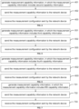
- FIG. 2 is a schematic flowchart illustrating a method for generating measurement capability information according to embodiments of the disclosure. It is noteworthy that the method for generating measurement capability information according to embodiments of the disclosure is performed by a terminal device. As illustrated in FIG. 2 , the method may include the following.
- measurement capability information is generated.
- the measurement capability information is configured to indicate terminal device capability(capabilities) of a terminal device related to a Synchronization Signal Block Measurement Timing Configuration (SMTC) and/or a Measurement Gap (MG).
- SMTC Synchronization Signal Block Measurement Timing Configuration
- MG Measurement Gap
- the terminal device may generate measurement capability information.
- the measurement capability information is configured to indicate terminal device capability(capabilities) of the terminal device related to a measurement window configuration.
- the measurement window configuration includes at least one of a SMTC (or called SSB-MTC) configuration or an MG configuration.
- the terminal device may send the generated measurement capability information to the network device, and the network device may configure a corresponding measurement configuration for the terminal device based on the measurement capability information.
- the measurement configuration includes the measurement-related configuration of the terminal device, and is not limited to the SMTC and/or MG configuration. That is, the measurement configuration includes a measurement window configuration.
- the measurement capability information includes at least one of:
- the measurement capability information may include any one or any multiple of the above seven types of capability information.
- the term "and/or" in the above capability information means that, as a first possible implementation, the capability information indicates capabilities of the terminal device related to the SMTC configuration, as a second possible implementation, the capability information indicates capabilities of the terminal device related to the MG configuration, and as a third possible implementation, the capability information indicates capabilities of the terminal device related to the SMTC and MG configurations.
- the first capability information is configured to indicate the number of SMTCs and/or MGs supported by the terminal device, in which the number includes a maximum number.
- the second capability information is configured to indicate whether the terminal device supports a first number of SMTCs and/or MGs, where the first number includes a maximum first number.
- the number of SMTCs” described in the capability information is the number of SMTCs configured per measured object or the number of SMTCs configured per measurement frequency
- the number of MGs” described in the capability information is configured per terminal device
- the number of MGs” described in the capability information is the number of MGs configured for a frequency range (FR1) or another frequency range (FR2).
- the number of STMCs mentioned in the capability information is for one measured object or one measurement frequency, and the number of SMTCs corresponding to different measured objects and different measurement frequency may be different.
- the number of MGs mentioned in the capability information is for one terminal device or one frequency range, and the number of MGS corresponding to different terminal devices and different frequency ranges FR1 and FR2 may be different.
- the measurement capability information of the terminal device may further be configured to indicate the capability information per type of period of at least one type of period of the measurement window configuration supported by the terminal device and/or to indicate the capability information per type of length of at least one type of length of the measurement window configuration supported by the terminal device.
- the measurement capability information of the terminal device may further be configured to indicate the capability information per type of pattern of at least one type of pattern of the measurement window configuration supported by the terminal device.
- the pattern of the measurement window configuration is determined by the period and length of the measurement window configuration.
- the measurement capability information of the terminal device further includes at least one of pattern capability information, period capability information, or length capability information.
- the pattern capability information is configured to indicate the capability information per type of pattern of at least one type of pattern of the measurement window configuration supported by the terminal device.
- the period capability information is configured to indicate the capability information per type of period of at least one type of period of the measurement window configuration supported by the terminal device.
- the length capability information is configured to indicate the capability information per type of length of at least one type of length of the measurement window configuration supported by the terminal device.
- the terminal device may send the measurement capability information to the network device.
- the measurement capability information is contained in information on the terminal device capability(capabilities), as a terminal device capability Information Element (IE) and the terminal device sends the information on the terminal device capability(capabilities) to the network device.
- IE terminal device capability Information Element
- the measurement capability is contained in a terminal device capability IE. That is, the terminal device sends the information on the terminal device capability(capabilities) to the network device, in which the information on the terminal device capability(capabilities) includes at least one terminal device capability IE, and the measurement information is included in one terminal device capability IE among the at least one terminal device capability IE.
- the measurement capability information is included in assistant information, and the terminal device sends the assistant information to the network device.
- the terminal device may also receive the measurement configuration sent by the network device.
- the terminal device in response to the measurement configuration not meeting the terminal device capability(capabilities), the terminal device sends an indication to the network device, in which the indication is used for requesting the network device to reconfigure the measurement configuration.
- the terminal device may send the indication to the network device to request the network device to reconfigure the measurement configuration for the terminal device.
- the measurement capability information in which the measurement capability information is configured to indicate the terminal device capability(capabilities) related to the SMTC and/or the MG of the terminal device, different terminal devices may balance, based on their own constraints and requirements, the computing processing power, the power consumption, and the mobility management performance, to obtain more precise measurement configurations that are more suitable for the terminal devices respectively, thereby effectively improving the communication efficiency of the communication system.
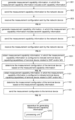
- FIG. 3 is a schematic flowchart illustrating a method for generating measurement capability information according to embodiments of the disclosure. It is noteworthy that the method for generating measurement capability information according to embodiments of the disclosure is performed by a terminal device. As illustrated in FIG. 3 , the method may include the following.
- measurement capability information is generated.
- the measurement capability information includes first capability information.
- the first capability information is configured to indicate the number of SMTCs and/or MGs supported by the terminal device.
- the number includes a maximum number.
- the first capability information may be configured to indicate the number of SMTCs and/or MGs supported by the terminal device, or may be configured to indicate the maximum number of SMTCs and/or MGs supported by the terminal device.
- the first capability information is at least configured to: indicate the number of parallel configured SMTCs and/or MGs supported by the terminal device, and/or indicate the number of parallel used SMTCs and/or MGs supported by the terminal device.
- the first capability information includes at least one of first configuration capability information or first use capability information.
- the first capability information is configured to indicate the number of SMTCs supported by the terminal device.
- the first configuration capability information is configured to indicate the number of parallel configured SMTCs supported by the terminal device.
- the first use capability information is configured to indicate the number of parallel used SMTCs supported by the terminal device.
- the first configuration capability information may be represented by an integer.
- the first configuration capability information is expressed as configsmtcnumber-v17 a, indicating that the terminal device supports to configure a SMTCs in parallel, where 0 ⁇ a ⁇ n and n is the maximum number of SMTCs that may be configured specified by the network or the protocol.
- the first use capability information may be represented by an integer.
- the first use capability information is expressed as usedsmtcnumber-v17 a, indicating that the terminal device supports to use a SMTCs in parallel, where 0 ⁇ a ⁇ n and n is the maximum number of SMTCs that may be configured specified by the network or the protocol.
- the first capability information is configured to indicate the maximum number of SMTCs supported by the terminal device.
- the first configuration capability information is configured to indicate the maximum number of parallel configured SMTCs supported by the terminal device.
- the first use capability information is configured to indicate the maximum number of parallel used SMTCs supported by the terminal device.
- the first configuration capability information may be represented by an integer.
- the first configuration capability information is expressed as maxconfigsmtcnumber-v17 a, indicating that the terminal device supports to configure in parameter at most a SMTCs, where 0 ⁇ a ⁇ n and n is the maximum number of SMTCs that may be configured specified by the network or the protocol.
- the first use capability information may be represented by an integer.
- the first use capability information is expressed as maxusedsmtcnumber-v17 a, indicating that the terminal device supports to use in parallel at most a SMTCs, where 0 ⁇ a ⁇ n, n is the maximum number of SMTCs that may be configured specified by the network or the protocol.
- the first capability information is configured to indicate the number of MGs supported by the terminal device.
- the first configuration capability information is configured to indicate the number of parallel configured MGs supported by the terminal device.
- the first use capability information is configured to indicate the number of parallel used MGs supported by the terminal device.
- the first configuration capability information may be represented by an integer.
- the first configuration capability information is expressed as configgapnumber-v17 a, indicating that the terminal device supports to configure in parallel a MGs, where 0 ⁇ a ⁇ n and n is the maximum number of MGs that may be configured specified by the network or the protocol.
- the first use capability information may be represented by an integer.
- the first use capability information is expressed as usedgapnumber-v17 a, indicating that the terminal device supports to use in parallel a MGs, where 0 ⁇ a ⁇ n and n is the maximum number of MGs that may be configured specified by the network or the protocol.
- the first capability information is configured to indicate the maximum number of MGs supported by the terminal device.
- the first configuration capability information is configured to indicate the maximum number of parallel configured MGs supported by the terminal device.
- the first use capability information is configured to indicate the maximum number of parallel used MGs supported by the terminal device.
- the first configuration capability information may be represented by an integer.
- the first configuration capability information is expressed as maxconfiggapnumber-v17 a, indicating that the terminal device supports to configure in parallel at most a MGs, where 0 ⁇ a ⁇ n and n is the maximum number of MGs that may be configured specified by the network or the protocol.
- the first use capability information may be represented by an integer.
- the first use capability information is expressed as maxusedgapnumber-v17 a, indicating that the terminal device supports to use in parallel at most a MGs, where 0 ⁇ a ⁇ n and n is the maximum number of MG that may be configured specified by the network or the protocol.
- the first capability information is configured to indicate the number of SMTCs and MGs supported by the terminal device.
- the first configuration capability information is configured to indicate the number of parallel configured SMTCs and MGs supported by the terminal device.
- the first use capability information is configured to indicate the number of parallel used SMTCs and MGs supported by the terminal device.
- the first capability information is configured to indicate the maximum number of SMTCs and MGs supported by the terminal device.
- the first configuration capability information is configured to indicate the maximum number of parallel configured SMTCs and MGs supported by the terminal device.
- the first use capability information is configured to indicate the maximum number of parallel used SMTCs and MGs supported by the terminal equipment.
- the first capability information may also be configured to indicate the number of SMTCs supported by the terminal device corresponding to at least one type of SMTC period supported by the terminal device; and/or indicate the number of MGs supported by the terminal device corresponding to at least one type of MG period supported by the terminal device; and/or indicate the number of SMTCs supported by the terminal device corresponding to at least one type of SMTC length supported by the terminal device; and/or indicate the number of MGs supported by the terminal device corresponding to at least one type of MG length supported by the terminal device.
- the first capability information may also be configured to indicate the number of SMTCs supported by the terminal device corresponding to at least one type of SMTC pattern supported by the terminal device; and/or, indicate the number of MGs supported by the terminal device corresponding to at least one type of MG pattern supported by the terminal device.
- the first capability information further includes at least one of first pattern capability information, first period capability information or first length capability information.
- the first pattern capability information is configured to indicate the number of SMTCs or a maximum number of SMTCs supported by the terminal device per type of SMTC pattern of at least one type of SMTC pattern supported by the terminal device, and/or indicate the number of MCs or a maximum number of MGs supported by the terminal device per type of MG pattern of at least one type of MG pattern supported by the terminal device.
- the first period capability information is configured to indicate the number of SMTCs or the maximum number of SMTCs supported by the terminal device per type of SMTC period of at least one type of SMTC period supported by the terminal device, and/or indicate the number of MCs or the maximum number of MGs supported by the terminal device per type of MG period of at least one type of MG period supported by the terminal device.
- the first length capability information is configured to indicate the number of SMTCs or the maximum number of SMTCs supported by the terminal device per type of SMTC length of at least one type of SMTC length supported by the terminal device, and/or indicate the number of MGs or the maximum number of MGs supported by the terminal device per type of MG length of at least one type of MG length supported by the terminal device.
- the SMTC pattern is determined by the SMTC length and period configurations. If any of the period and the length is different, a different SMTC pattern will be generated. Each SMTC pattern has a respective SMTC pattern identifier (ID) to distinguish different SMTC patterns.
- ID SMTC pattern identifier
- the MG pattern is determined by the MG length and period configurations. If any of the period and the length is different, a different MG pattern will be generated. Each MG pattern has a respective MG pattern ID to distinguish different MG patterns.
- the first period capability information may be represented through an integer sequence, and each element in the sequence represents the number of parallel configured SMTCs supported by a corresponding period.
- the first period capability information is expressed as configsmtcnumperperiod SEQUENCE(SIZE (b)) OF INTEGER (0...n), indicating the number of parallel configured SMTCs supported by the terminal device corresponding to each SMTC period of b types of SMTC period supported by the terminal device, wherein 0 ⁇ b ⁇ m, m is the number of SMTC periods that may be configured for the terminal device, n is the maximum number of SMTCs that may be configured specified by the network or the protocol, and SIZE represents a length of the sequence. That is, the length of the sequence is b, and a respective integer at each position of the sequence is the number of parallel configured SMTCs supported by the terminal device corresponding to each type of period.
- configsmtcnumperperiod b 1 b 2 b 3 indicates that the terminal device supports to configure in parallel b 1 SMTCs within the SMTC period 1, the terminal device supports to configure in parallel b 2 SMTCs within the SMTC period 2, and the terminal device supports to configure in parallel b 3 SMTCs within the SMTC period 3.
- the first period capability information may be represented by an integer sequence, and each element in the sequence represents the maximum number of parallel configured SMTCs supported by a corresponding period.
- the first period capability information is expressed as maxconfigsmtcnumperperiod SEQUENCE(SIZE (b)) OF INTEGER (O...n), indicating the maximum number of parallel configured SMTCs supported by the terminal device corresponding to each type of SMTC period among the b types of SMTC periods supported by the terminal device, where 0 ⁇ b ⁇ m, m is the number of SMTC periods that may be configured for the terminal device, n is the maximum number of SMTCs that may be configured specified by the network or the protocol, and SIZE represents a length of the sequence.
- maxconfigsmtcnumperperiod b 1 b 2 b 3 means that the terminal device supports to configure in parallel at most b 1 SMTCs within the SMTC period 1, the terminal device supports to configure in parallel at most b 2 SMTCs within the SMTC period 2, and the terminal device supports to configure in parallel at most b 3 SMTCs within the SMTC period 3.
- the first period capability information may be represented by an integer sequence, and each element in the sequence represents the number of parallel configured MGs supported by a corresponding period.
- the first period capability information is expressed as configgapnumperperiod SEQUENCE(SIZE (b)) OF INTEGER (O...n), indicating the number of parallel configured MGs supported by the terminal device corresponding to each type of MG period among the b types of MG periods supported by the terminal device, where 0 ⁇ b ⁇ m, m is the number of MG periods that may be configured for the terminal device, n is the maximum number of MGs that may be configured specified by the network or the protocol, SIZE represents a length of the sequence, and INTEGER represents an integer.
- configgapnumperperiod b 1 b 2 b 3 indicates that the terminal device supports to configure in parallel b 1 MGs within the MG period 1, the terminal device supports to configure in parallel b 2 MGs within the MG period 2, and the terminal device supports to configure in parallel b 3 MGs within the MG period 3.
- the first period capability information may be represented by an integer sequence, and each element in the sequence represents the maximum number of parallel configured MGs supported by a corresponding period.
- the first period capability information is expressed as maxconfiggapnumperperiod SEQUENCE(SIZE (b)) OF INTEGER (O...n), indicating the maximum number of parallel configured MGs supported by the terminal device corresponding to each type of MG period among the b types of MG periods supported by the terminal device, where 0 ⁇ b ⁇ m, m is the number of MG periods that may be configured for the terminal device, n is the maximum number of MGs that may be configured specified by the network or the protocol, SIZE represents a length of the sequence, and INTEGER represents an integer.
- maxconfiggapnumperperiod b 1 b 2 b 3 means that the terminal device supports to configure in parameter at most b 1 MGs within the MG period 1, the terminal device supports to configure in parameter at most b 2 MGs within the MG period 2; and the terminal device supports to configure in parameter at most b 3 MGs within the MG period 3.
- the first period capability information may be represented by an integer sequence, and each element in the sequence represents the number of parallel used SMTCs supported by a corresponding period.
- the first period capability information is expressed as usedsmtcnumperperiod SEQUENCE(SIZE (b)) OF INTEGER (O...n), indicating the number of parallel used SMTCs supported by the terminal device corresponding to each type of SMTC period among the b types of SMTC periods supported by the terminal device, wherein, 0 ⁇ b ⁇ m, m is the number of SMTC periods that may be configured for the terminal device, n is the maximum number of SMTCs that may be configured specified by the network or the protocol, and SIZE represents a length of the sequence.
- the length of the sequence is b, and a respective integer at each position in the sequence is the number of parallel used SMTCs supported by the terminal device corresponding to a corresponding period.
- usedsmtcnumperperiod b1b2b3 means that the terminal device supports to use in parallel b 1 SMTCs within the SMTC period 1, the terminal device supports to use in parallel b 2 SMTCs within the SMTC period 2, and the terminal device supports to use in parallel b 3 SMTCs within the SMTC period 3.
- the first period capability information may be configured to indicate the maximum number of parallel used SMTCs supported by the terminal device corresponding to each type of SMTC period among at least one type of SMTC period supported by the terminal device.
- the first period capability information may be represented by an integer sequence, and each element in the sequence represents the number of parallel used SMTCs supported by a corresponding period.
- the first period capability information may be configured to indicate the number of parallel used MGs or the maximum number of parallel used MGs supported by the terminal device corresponding to each type of MG period among at least one type of MG period supported by the terminal device, which is similar to the case that the first period capability information indicates the number or the maximum number of SMTCs supported by the terminal device corresponding to each SMTC period and are not repeated here.
- representation manners of the first length capability information and the first pattern capability information are similar to those of the first period capability information, which are not repeated here.
- the measurement capability information is sent to the network device.
- the measurement capability information is included in the information on the terminal device capability(capabilities) as a terminal device capability IE, and the terminal device sends the information on the terminal device capability(capabilities) to the network device.
- the measurement capability is included in a terminal device capability IE. That is, the terminal device sends the information on the terminal device capability(capabilities) to the network device, in which the information on the terminal device capability(capabilities) includes at least one terminal device capability IE, and the measurement information is included in one terminal device capability IE of the at least one terminal device capability IE.
- the measurement capability information may be included in measurement and mobility parameters (MeasAndMobParameters), measurement and mobility parameters of multi-radio access technology dual connectivity (Multi-RATDual Connectivity, MRDC) (MeasAndMobParametersMRDC), NR UE Radio Access Capability (UE-NR-Capability) or other terminal equipment capability lEs.
- Measurement and mobility parameters Measurement and mobility parameters of multi-radio access technology dual connectivity
- MRDC Multi-RATDual Connectivity
- UE-NR-Capability NR UE Radio Access Capability
- UE-NR-Capability NR UE Radio Access Capability
- the measurement capability information is included in assistant information, and the terminal device sends the assistant information to the network device.
- step 303 the measurement configuration sent by the network device is received.
- the measurement configuration is determined by the network device based on the measurement capability information.
- the terminal device receives the measurement configuration determined, based on the measurement capability information, by the network device.
- the terminal device in response to the measurement configuration not meeting the terminal device capability(capabilities), the terminal device sends an indication to the network device, in which the indication is used for requesting the network device to reconfigure the measurement configuration.
- the terminal device may send the indication to the network device for requesting the network device to reconfigure the measurement configuration for the terminal device.
- the measurement capability information in which the measurement capability information includes the first capability information
- different terminal devices may balance, based on their own restrictions and requirements, the computing processing power, the power consumption, and the mobility management performance, to obtain more precise measurement configurations that are more suitable for the terminal devices respectively, thereby effectively improving the communication efficiency of the communication system.
- FIG. 4 is a schematic flowchart illustrating a method for generating measurement capability information according to embodiments of the disclosure. It is noteworthy that the method for generating measurement capability information according to embodiments of the disclosure is performed by a terminal device. As illustrated in FIG. 4 , the method may include the following.
- step 401 measurement capability information is generated, in which the measurement capability information includes second capability information.
- the second capability information is configured to indicate whether the terminal device supports the first number of SMTCs and/or MGs.
- the first number includes a maximum first number.
- the second capability information may be configured to indicate whether the terminal device supports the first number of SMTCs and/or MGs, or indicate whether the terminal device supports less than the first number of SMTCs and/or MGs.
- the second capability information is at least configured to: indicate whether the terminal device supports to configure in parallel the first number of SMTCs and/or MGs, and/or indicate whether the terminal device supports to use in parallel the first number of SMTCs and/or MGs.
- the second capability information includes at least one of second configuration capability information and second use capability information.
- the second capability information is configured to indicate whether the terminal device supports the first number of SMTCs.
- the second configuration capability information is configured to indicate whether the terminal device supports to configure in parallel the first number of SMTCs.
- the second use capability information is configured to indicate whether the terminal device supports to use in parallel the first number of SMTCs.
- the second configuration capability information may be represented by an enumeration type, and the optional value is "supported”. When it is "supported”, it indicates that the terminal device supports to configure in parallel the first number of SMTCs.
- ENUMERATED means the enumerated type.
- 2configsmtc ENUMERATED ⁇ supported ⁇ means that the terminal device supports to configured in parallel 2 SMTCs.
- the second use capability information may be represented by an enumeration type, and the optional value is "supported”. When it is "supported”, it indicates that the terminal device supports to use in parallel the first number of SMTCs.
- 2usedsmtc ENUMERATED ⁇ supported ⁇ indicates that the terminal device supports to use in parallel 2 SMTCs.
- the terminal device may support multiple types of SMTC quantity
- the second capability information may indicate whether the terminal device supports each of the multiple types of SMTC quantity.
- the second configuration capability information may be represented by a bit string, and a respective bit value of each element in the string indicates whether the terminal device supports to configure in parallel a corresponding quantity of SMTCs, where the corresponding quantity is the type of SMTC quantity corresponding to the element.
- the second configuration capability information is expressed as supportedconfigSMTCnumber BIT STRING (SIZE (n)), where n represents the total number of the types of the SMTC quantities supported by the terminal device that needs to indicate.
- SIZE (n) indicates that a length of the bit string is n.
- the bit value of a bit being 1 indicates that the terminal device supports a corresponding quantity of SMTCs, where the corresponding quantity is the type of SMTC quantity corresponding to the bit, while the bit value being 0 indicates that the terminal device does not support the corresponding quantity of SMTCs. It is understandable that the bit value being 0 may indicate that the terminal device supports the corresponding quantity of SMTCs, while the bit value being 1 indicates that the terminal device does not support the corresponding quantity of SMTCs. For example, it needs to indicate whether the terminal device supports two types of SMTC quantity.
- the second configuration capability information is supportedconfigSMTCnumber 10
- the second use capability information may be represented through a bit string, and a respective bit value of each element in the string indicates whether the terminal device supports to use in parallel a corresponding number of SMTCs, where the corresponding number is the type of SMTC quantity corresponding to the element.
- the second use capability information is expressed as supportedusedSMTCnumber BIT STRING (SIZE (n)), where n represents a total number of the types of the SMTC quantities supported by the terminal device that needs to indicate.
- SIZE (n) indicates that a length of the bit string is n.
- the bit value of a bit being 1 indicates that the terminal device supports a corresponding quantity of SMTCs, where the corresponding quantity is the type of SMTC quantity corresponding to the bit, while the bit value being 0 indicates that the terminal device does not support the corresponding quantity of SMTCs. It is understandable that the bit value being 0 may indicate that the terminal device supports the corresponding quantity of SMTCs, while the bit value being 1 indicates that the terminal device does not support the corresponding quantity of SMTCs. For example, it needs to indicate whether the terminal device supports two types of SMTC quantity.
- the second configuration capability information is supportedconfigSMTCnumber 01, it indicates that the terminal device does not support to configure in parallel a first quantity of SMTCs, where the first quantity is the first type of SMTC quantity, but supports to configure in parallel a second quantity of SMTCs, where the second quantity is the second type of SMTC quantity.
- the second capability information is configured to indicate whether the terminal device supports no more than the first number of SMTCs.
- the second configuration capability information is configured to indicate whether the terminal device supports to configure in parallel no more than the first number of SMTCs.
- the second use capability information is configured to indicate whether the terminal device supports to use in parallel no more than the first number of SMTCs.
- the second configuration capability information may be represented by an enumeration type, and the optional value is "supported”. When it is "supported”, it indicates that the terminal device supports to configure in parallel no more than the first number of SMTCs.
- ENUMERATED means the enumerated type. For example, 2maxconfigsmtc ENUMERATED ⁇ supported ⁇ indicates that the terminal device supports to configure in parallel no more than 2 SMTCs.
- the second use capability information may be represented by an enumeration type, and the optional value is "supported”. When it is "supported”, it indicates that the terminal device supports to use in parallel no more than the first number of SMTCs.
- the ENUMERATED means the enumerated type. For example, 2maxusedsmtc ENUMERATED ⁇ supported ⁇ indicates that the terminal device supports to use in parallel no more than 2 SMTCs.
- the terminal device may support multiple types of SMTC quantity
- the second capability information may indicate whether the terminal device supports each of the multiple types of SMTC quantity.
- the second capability information is configured to indicate whether the terminal device supports the first number of MGs.
- the second configuration capability information is configured to indicate whether the terminal device supports to configure in parallel the first number of MGs.
- the second use capability information is configured to indicate whether the terminal device supports to use in parallel the first number of MGs.
- the second configuration capability information may be represented by an enumeration type, and the optional value is "supported”. When it is "supported”, it indicates that the terminal device supports to configure in parallel the first number of MGs.
- the ENUMERATED means the enumerated type. For example, 2configgap ENUMERATED ⁇ supported ⁇ indicates that the terminal device supports to configure in parallel 2 MGs.
- the second use capability information may be represented by an enumeration type, and the optional value is "supported”. When it is "supported”, it indicates that the terminal device supports to use in parallel the first number of MGs.
- the ENUMERATED means the enumerated type. For example, 2usedgap ENUMERATED ⁇ supported ⁇ indicates that the terminal device supports to use in parallel 2 MGs.
- the terminal device may support multiple types of MG quantity
- the second capability information may indicate whether the terminal device supports each of the multiple types of MG quantity.
- the second configuration capability information may be represented by a bit string, and a respective bit value of each element in the string indicates whether the terminal device supports to configure in parallel a corresponding quantity of MGs, where the corresponding quantity is the type of MG quantity corresponding to the element.
- the second configuration capability information is expressed as supportedconfigGAPnumber BIT STRING (SIZE (n)), where n represents the total number of the types of the MG quantities supported by the terminal device that needs to indicate.
- SIZE(n) indicates that a length of the bit string is n.
- the bit value of a bit being 1 indicates that the terminal device supports a corresponding quantity of MGs, where the corresponding quantity is the type of MG quantity corresponding to the bit, while the bit value being 0 indicates that the terminal device does not support the corresponding quantity of MGs.
- the bit value being 0 may indicate that the terminal device supports the corresponding quantity of MGs, while the bit value being 1 indicates that the terminal device does not support the corresponding quantity of MGs. For example, it needs to indicate whether the terminal device supports two types of MG quantity. If the second configuration capability information is supportedconfigGAPnumber 10, it indicates that the terminal device supports to configure in parallel a first quantity of MGs, where the first quantity is the first type of MG quantity, but does not support to configure in parallel a second quantity of MGs, where the second quantity is the second type of MG quantity.
- the second use capability information may be represented by a bit string, and a respective bit value of each element in the string indicates whether the terminal device supports to use in parallel a corresponding number of MGs, where the corresponding number is the type of MG quantity corresponding to the element.
- the second use capability information is expressed as supportedusedGAPnumber BIT STRING (SIZE (n)), where n represents a total number of the types of the MG quantities supported by the terminal device that needs to indicate.
- SIZE(n) indicates that a length of the bit string is n.
- the bit value of a bit being 1 indicates that the terminal device supports a corresponding quantity of MGs, where the corresponding quantity is the type of MG quantity corresponding to the bit, while the bit value being 0 indicates that the terminal device does not support the corresponding quantity of MGs.
- the bit value being 0 may indicate that the terminal device supports the corresponding quantity of MGs, while the bit value being 1 indicates that the terminal device does not support the corresponding quantity of MGs. For example, it needs to indicate whether the terminal device supports two MG quantities of MGs. If the second configuration capability information is supportedusedGAPnumber 01, it indicates that the terminal device does not support to configure in parallel a first quantity of MGs, where the first quantity is the first type of MG quantity, but supports to configure in parallel a second quantity of MGs, where the second quantity is the second type of MG quantity.
- the second capability information is configured to indicate the maximum number of MGs supported by the terminal device.
- the second configuration capability information is configured to indicate whether the terminal device supports to configure in parallel no more than the first number of MGs.
- the second use capability information is configured to indicate whether the terminal device supports to use in parallel no more than the first number of MGs.
- the second configuration capability information may be represented by an enumeration type, and the optional value is "supported”. When it is "supported”, it indicates that the terminal device supports to configure in parallel no more than the first number of MGs.
- ENUMERATED means the enumerated type. For example, 2maxconfiggap ENUMERATED ⁇ supported ⁇ indicates that the terminal device supports to configure in parallel no more than 2 MGs.
- the second use capability information may be represented by an enumeration type, and the optional value is "supported”. When it is "supported”, it indicates that the terminal device supports to use in parallel no more than the first number of MGs.
- the ENUMERATED means the enumerated type. For example, 2maxusedgap ENUMERATED ⁇ supported ⁇ indicates that the terminal device supports to use in parallel no more than 2 MGs.
- the terminal device may support multiple types of MG quantity
- the second capability information may indicate whether the terminal device supports each of the multiple types of MG quantity.
- the second capability information is configured to indicate whether the terminal device supports the first number of SMTCs and MGs.
- the second configuration capability information is configured to indicate whether the terminal device supports to configure in parallel the first number of SMTCs and MGs.
- the second use capability information is configured to indicate whether the terminal device supports to use in parallel the first number of SMTCs and MGs.
- the second capability information is configured to indicate whether the terminal device supports no more than the first number of SMTCs and MGs.
- the second configuration capability information is configured to indicate whether the terminal device supports to configure in parallel no more than the first number of SMTCs and MGs.
- the second use capability information is configured to indicate whether the terminal device supports to use in parallel no more than the first number of SMTCs and MGs.
- the second capability information is further configured to indicate whether the terminal device supports the first number of SMTCs per type of SMTC period of at least one type of SMTC period supported by the terminal device, and/or to indicate whether the terminal device supports the first number of MGs per type of MG period of at least one type of MG period supported by the terminal device, and/or indicate whether the terminal device supports the first number of SMTCs per type of SMTC length of at least one type of SMTC length supported by the terminal device, and/or indicate whether the terminal device supports the first number of MGs per type of MG length of at least one type of MG length supported by the terminal device.
- the second capability information is further configured to indicate whether the terminal device supports the first number of SMTCs per type of SMTC pattern of at least one type of SMTC pattern supported by the terminal device, and/or indicate whether the terminal device supports the first number of MGs per type of MG pattern of at least one type of MG pattern supported by the terminal device.
- the second capability information further includes at least one of second pattern capability information, second period capability information or second length capability information.
- the second pattern capability information is configured to indicate whether the terminal device supports the first number of SMTCs or no more than the first number of SMTCs per type of SMTC pattern of at least one type of SMTC pattern supported by the terminal device and/or indicate whether the terminal device supports the first number of MGs or no more than the first number of MGs per type of MG pattern of at least one type of MG pattern supported by the terminal device.
- the second period capability information is configured to indicate whether the terminal device supports the first number of SMTCs or no more than the first number of SMTCs per type of SMTC period of at least one type of SMTC period supported by the terminal device; and/or indicate whether the terminal device supports the first number of MGs or no more than the first number of MGs per type of MG period of at least one type of MG period supported by the terminal device.
- the second length capability information is configured to indicate whether the terminal device supports the first number of SMTCs or no more than the first number of SMTCs per type of SMTC length of at least one type of SMTC length supported by the terminal device, and/or indicate whether the terminal device supports the first number of MGs or no more than the first number of MGs per type of MG length of at least one type of MG length supported by the terminal device.
- the SMTC pattern is determined by the SMTC length and period configurations. If any of the period and the length is different, a different SMTC pattern will be generated. Each SMTC pattern has a respective SMTC pattern ID to distinguish different SMTC patterns.
- the MG pattern is determined by the MG length and period configurations. If any of the period and the length is different, a different MG pattern will be generated. Each MG pattern has a respective MG pattern ID to distinguish different MG patterns.
- the second period capability information may be represented through a bit string, and a respective bit value of each element in the string indicates whether the terminal device supports to configure in parallel the first number of SMTCs within a period corresponding to the element.
- the second period capability information is expressed as Xconfigsmtcnumperperiod BIT STRING (SIZE (b)), indicating whether the terminal device supports to configure in parallel X SMTCs per type of SMTC period of the b types of SMTC period supported by the terminal device, where 0 ⁇ b ⁇ m, m is the number of SMTC periods that may be configured for the terminal device, and SIZE indicates a length of the bit string. That is, the length of the bit string is b, and a respective bit value at each position in the string indicates whether the terminal device supports to configure in parallel X SMTCs within each period.
- SIZE b
- the bit value being 1 indicates that the terminal device supports a corresponding-type quantity of SMTCs, while the bit value being 0 indicates that the terminal equipment does not support the corresponding-type quantity of SMTCs. It is understandable that the bit value being 0 indicates that the terminal device supports the corresponding-type quantity of SMTCs, while the bit value being 1 indicates that the terminal device does not support the corresponding-type quantity of SMTCs.
- 2configsmtcnumperperiod 100 means that the terminal device supports to configure in parallel 2 SMTCs within the SMTC period 1, the terminal device does not support to configure in parallel 2 SMTCs within the SMTC period 2, and the terminal device does not support to configure in parallel 2 SMTCs within the SMTC period 3.
- the second period capability information may be represented through a bit string, and a respective bit value of each element in the string indicates whether the terminal device supports to configure in parallel no more than the first number of SMTCs within a period corresponding to the element.
- the second period capability information is represented as Xmaxconfigsmtcnumperiod BIT STRING (SIZE (b)), indicating whether the terminal device supports to configure in parallel no more than X SMTCs per type of SMTC period of the b types of SMTC period supported by the terminal device, where 0 ⁇ b ⁇ m, m is the number of SMTC periods that may be configured for the terminal device, and SIZE indicates a length of the bit string. That is, the length of the bit string is b, and a respective bit value at each position in the string indicates whether the terminal device supports to configure in parallel no more than X SMTCs within each period.
- SIZE indicates a length of the bit string. That is, the length of the bit string is b, and a respective bit value at each position in the string indicates whether the terminal device supports to configure in parallel no more than X SMTCs within each period.
- bit value of a bit being 1 indicates that the terminal device supports a corresponding-type quantity of SMTCs, while the bit value being 0 indicates that the terminal equipment does not support the corresponding-type quantity of SMTCs. It is understandable that the bit value being 0 indicates that the terminal device supports the corresponding-type quantity of SMTCs, while the bit value being 1 indicates that the terminal device does not support the corresponding-type quantity of SMTCs.
- 2maxconfigsmtcnumperperiod 110 means that the terminal device supports to configure in parallel no more than 2 SMTCs within the SMTC period 1; the terminal device supports to configure in parallel no more than 2 SMTCs within the SMTC period 2; and the terminal device does not support to configure in parallel no more than 2 SMTCs within the SMTC period 3.
- the second period capability information may be represented through a bit string, and a respective bit value of each element in the string indicates whether the terminal device supports to configure in parallel the first number of MGs within a period corresponding to the element.
- the second period capability information is expressed as Xconfiggapnumperperiod BIT STRING (SIZE (b)), indicating whether the terminal device supports to configure in parallel X MGs per type of MG period of the b types of MG period supported by the terminal device, where 0 ⁇ b ⁇ m, m is the number of MG periods configured for the terminal device, and SIZE indicates a length of the bit string. That is, the length of the bit string is b, and a respective bit value at each position in the string indicates whether the terminal device supports to configure in parallel X MGs within in each period.
- the bit value being 1 indicates that the terminal device supports a corresponding-type quantity of MGs, while the bit value being 0 indicates that the terminal device does not support the corresponding-type quantity of MGs. It is understandable that the bit value being 0 indicates that the terminal device supports the corresponding-type quantity of MGs, while the bit value being 1 indicates that the terminal device does not support the corresponding-type quantity of MGs.
- 2configgapnumperperiod 001 means that the terminal device does not support to configure in parallel 2 MGs within the MG period 1, the terminal device does not support to configure in parallel 2 MGs within the MG period 2, and the terminal device supports to configure in parallel 2 MGs within the MG period 3.
- the second period capability information may be represented through a bit string, and a respective bit value of each element in the string indicates whether the terminal device supports to configure in parallel no more than the first number of MGs within a period corresponding to the element.
- the second period capability information is expressed as Xmaxconfiggapnumperperiod BIT STRING (SIZE (b)), indicating whether the terminal device supports to configure in parallel no more than X MGs per type of MG period of the b types of MG period supported by the terminal device, where 0 ⁇ b ⁇ m, m is the number of MG periods that may be configured for the terminal device, and SIZE indicates a length of the bit string. That is, the length of the bit string is b, and a respective bit value at each position in the string indicates whether the terminal device supports to configure in parallel no more than X MGs within each period.
- bit value of a bit being 1 indicates that the terminal device supports a corresponding-type quantity of MGs, while the bit value being 0 indicates that the terminal device does not support the corresponding-type quantity of MGs. It is understandable that the bit value being 0 indicates that the terminal device supports the corresponding-type quantity of MGs, while the bit value being 1 indicates that the terminal device does not support the corresponding-type quantity of MGs.
- 2maxconfiggapnumperperiod 111 means that the terminal device supports to configure in parallel no more than 2 MGs within the MG period 1, the terminal device supports to configure in parallel no more than 2 MGs within the MG period 2, and the terminal device supports to configure in parallel no more than 2 MGs within the MG period 2.
- the second period capability information may be represented through a bit string, and a respective bit value of each element in the string indicates whether the terminal device supports to use in parallel the first number of SMTCs within a period corresponding to the element.
- the second period capability information is expressed as Xusedsmtcnumperperiod BIT STRING (SIZE (b)), indicating whether the terminal device supports to use in parallel X SMTCs per type of SMTC period of the b types of SMTC period supported by the terminal device, where 0 ⁇ b ⁇ m, m is the number of SMTC periods that may be configured for the terminal device, and SIZE indicates a length of the bit string. That is, the length of the bit string is b, and a respective bit value at each position in the string indicates whether the terminal device supports to use in parallel X SMTCs within each period.
- SIZE b
- bit value of a bit being 1 indicates that the terminal device supports the corresponding-type quantity of SMTCs, while the bit value being 0 indicates that the terminal device does not support the corresponding-type quantity of SMTCs. It is understandable that the bit value being 0 indicates that the terminal device supports the corresponding-type quantity of SMTCs, while the bit value being 1 indicates that the terminal device does not support the corresponding-type quantity of SMTCs.
- 2usedsmtcnumperperiod 101 means that the terminal device supports to use in parallel 2 SMTCs within the SMTC period 1, the terminal device does not support to use in parallel 2 SMTCs within the SMTC period 2, and the terminal device supports to use in parallel 2 SMTCs within the SMTC period 3.
- the second period capability information may further be configured to indicate whether the terminal device supports to use in parallel no more than the first number of SMTCs per type of SMTC period of at least one type of SMTC period supported by the terminal device.
- the second period capability information may be represented through a bit string, and a respective bit value of each element in the string indicates whether the terminal device supports to use in parallel no more than the first number of SMTCs within a period corresponding to the element.
- Xmaxusedsmtcnumperperiod 110 means that the terminal device supports to use in parallel no more than X SMTCs within the SMTC period 1, the terminal device supports to use in parallel no more than X SMTCs within the SMTC period 2, and the terminal device does not support to use in parallel no more than X SMTCs within the SMTC period 3.
- the second period capability information may further be configured to indicate whether the terminal device supports to use in parallel the first number of MGs or no more than the first number of MGs per type of MG period of at least one MG period supported by the terminal device, which is similar to the case that the second period capability information indicating whether the terminal device supports to use in parallel the first number of SMTCs or no more than the first number of SMTCs per each type of SMTC period and are not repeated here.
- the measurement capability information is sent to the network device.
- the measurement configuration sent by the network device is received.
- step 402 and step 403 may be performed in any way described in embodiments of the disclosure, which is not limited in embodiments of the disclosure and will not be repeated here.
- the measurement capability information in which the measurement capability information includes the second capability information
- different terminal devices may balance, based on their own restrictions and requirements, the computing processing power, the power consumption and the mobility management performance, to obtain more precise measurement configurations that are more suitable for the terminal devices respectively, thereby effectively improving the communication efficiency of the communication system.
- FIG. 5 is a schematic flowchart illustrating a method for generating measurement capability information according to embodiments of the disclosure. It is noteworthy that the method for generating measurement capability information according to embodiments of the disclosure is performed by a terminal device. As illustrated in FIG. 5 , the method may include the following.
- measurement capability information is generated, in which the measurement capability information includes third capability information.
- the third capability information is configured to indicate whether the terminal device supports an additional SMTC and/or MG.
- the number of basic measurement window configurations (SMTCs and/or MGs) of the terminal device is Y, where Y may be a non-negative integer such as any of 0, 1, 2, 3, 4 ...
- Y may be a non-negative integer such as any of 0, 1, 2, 3, 4 ...
- the basic measurement configuration may not meet the special scenarios, so some additional measurement configurations may need to be configured. Therefore, an indication for indicating whether the terminal device supports to configure additional SMTC and/or MG is needed.
- the number of additionally configured SMTCs and/or MGs may be one or multiple, and the number of additionally configured SMTCs and/or MGs is related to the application scenario required by the terminal device.
- the terminal device supports to configure one set of basic SMTC and/or MG.
- the terminal device supporting the feature A the terminal device needs to support 3 additional sets of SMTC and/or MG. Therefore, if supporting to configure the additional SMTC and/or MG, then the terminal device supports to configure at most 4 sets.
- the terminal device supporting the feature B the terminal device needs to support one additional set of SMTC and/or MG. Therefore, if supporting to configure the additional SMTC and/or MG, then the terminal device supports to configure at most 2 sets.
- the third capability information is at least configured to: indicate whether the terminal device supports to configure in parallel the additional SMTC and/or MG, and/or indicate whether the terminal device supports to use in parallel the additional SMTC and/or MG.
- the third capability information includes at least one of third configuration capability information or third use capability information.
- the third capability information is configured to indicate whether the terminal device supports the additional SMTC.
- the third configuration capability information is configured to indicate whether the terminal device supports to configure in parallel the additional SMTC.
- the third use capability information is configured to indicate whether the terminal device supports to use in parallel the additional SMTC.
- the third configuration capability information may be represented through an enumeration type, and the optional value is "supported”. When it is "supported”, it indicates that the terminal device supports to configure in parallel the additional SMTC.
- the third configuration capability information is represented as configadditinalsmtc ENUMERATED ⁇ supported ⁇ , indicating that the terminal device supports to configure in parallel the additional SMTC, where ENUMERATED represents an enumerated type.
- the third use capability information may be represented through an enumeration type, and the optional value is "supported”. When it is "supported”, it indicates that the terminal device supports to use in parallel the additional SMTC.
- the third use capability information is expressed as useadditinalsmtc ENUMERATED ⁇ supported ⁇ , indicating that the terminal device supports to use in parallel the additional SMTC, where ENUMERATED indicates an enumerated type.
- the third capability information is configured to indicate whether the terminal device supports the additional MG.
- the third configuration capability information is configured to indicate whether the terminal device supports to configure in parallel the additional MG.
- the third use capability information is configured to indicate whether the terminal device supports to use in parallel the additional MG.
- the third configuration capability information may be represented through an enumeration type, and the optional value is "supported”. When it is "supported”, it indicates that the terminal device supports to configure in parallel the additional MG.
- the third configuration capability information is expressed as configadditinalgap ENUMERATED ⁇ supported ⁇ , indicating that the terminal device supports to configure in parallel the additional MG, where ENUMERATED indicates an enumerated type.
- the third use capability information may be represented through an enumeration type, and the optional value is "supported”. When it is "supported”, it indicates that the terminal device supports to use in parallel the additional MG.
- the third use capability information is expressed as useadditinalgap ENUMERATED ⁇ supported ⁇ , indicating that the terminal device supports to use in parallel the additional MG, where ENUMERATED indicates an enumeration type.
- the third capability information is configured to indicate whether the terminal device supports the additional SMTC and MG.
- the third configuration capability information is configured to indicate whether the terminal device supports to configure in parallel the additional SMTC and MG.
- the third use capability information is configured to indicate whether the terminal device supports to use in parallel the additional SMTC and MG.
- the third capability information is further configured to indicate whether the terminal device supports the additional SMTC per type of SMTC period of at least one type of SMTC period supported by the terminal device; and/or to indicate whether the terminal device supports the additional MG per type of MG period of at least one type of MG period supported by the terminal device; and/or whether the terminal device supports the additional SMTC per type of SMTC length of at least one type Of SMTC length supported by the terminal device; and/or indicate whether the terminal device supports the additional MG per each type of MG length of at least one type of MG length supported by the terminal device.
- the third capability information is further configured to indicate whether the terminal device supports the additional SMTC per type of SMTC pattern of at least one type of SMTC pattern supported by the terminal device; and/or indicate whether the terminal device supports the additional MG per type of MG pattern of at least one type of MG pattern supported by the terminal device.
- the third capability information further includes at least one of third pattern capability information, third period capability information or third length capability information.
- the third pattern capability information is configured to indicate whether the terminal device supports the additional SMTC per type of SMTC pattern of at least one type of SMTC pattern supported by the terminal device; and/or indicate whether the terminal device supports the additional MG per type of MG pattern of at least one type of MG pattern supported by the terminal device.
- the third period capability information is configured to indicate whether the terminal device supports the additional SMTC per each type of SMTC period of at least one type of SMTC period supported by the terminal device; and/or indicate whether the terminal device supports the additional MG per each type of MG period of at least one type of MG period supported by the terminal device.
- the third length capability information is configured to indicate whether the terminal device supports the additional SMTC per each type of SMTC length of at least one type of SMTC length supported by the terminal device; and/or indicate whether the terminal device supports the additional MG per each type of MG length of at least one type of MG length supported by the terminal device.
- the SMTC pattern is determined by the SMTC length and period configurations. If any of the period and length is different, a different SMTC pattern will be generated. Each SMTC pattern has a corresponding SMTC pattern ID to distinguish different SMTC patterns.
- the MG pattern is determined by the MG length and period configurations. If any of the period and length is different, a different MG pattern will be generated. Each MG pattern has a corresponding MG pattern ID to distinguish different MG patterns.
- the third period capability information may be represented through a bit string, and a respective bit value of each element in the string indicates whether the terminal device supports to configure in parallel the additional SMTC within a period corresponding to the element.
- the third period capability information is expressed as configadditinalsmtcnumperperiod BIT STRING (SIZE (b)), indicating whether the terminal device supports to configure in parallel the additional SMTC per type of SMTC period of the b types of SMTC period supported by the terminal device, where 0 ⁇ b ⁇ m, m is the number of SMTC periods that may be configured for the terminal device, and SIZE indicates a length of the bit string. That is, the length of the bit string is b, and a respective bit value at each position in the string indicates whether the terminal device supports the additional SMTC within each type of period.
- SIZE indicates a length of the bit string. That is, the length of the bit string is b, and a respective bit value at each position in the string indicates whether the terminal device supports the additional SMTC within each type of period.
- bit value of a bit being 1 indicates that the terminal device supports the additional SMTC within a corresponding period, while the bit value being 0 indicates that the terminal device does not support the additional SMTC within the corresponding period. It is understandable that the bit value being 0 indicates that the terminal device supports the additional SMTC within the corresponding period, while the bit value being 1 indicates that the terminal device does not support the additional SMTC within the corresponding period.
- configadditionalsmtcnumperperiod 100 means that the terminal device supports to configure in parallel the additional SMTC within the SMTC period 1; the terminal device does not support to configure in parallel the additional SMTC within the SMTC period 2; and the terminal device does not support to configure in parallel the additional SMTC within the SMTC period 3.
- the third period capability information may be represented through a bit string, and a respective bit value of each element in the string indicates whether the terminal device supports to configure in parallel the additional MG within a period corresponding to the element.
- the third period capability information is expressed as configadditionalgapnumperperiod BIT STRING (SIZE (b)), indicating whether the terminal device supports to configure in parallel the additional MG per type of MG period of the b types of MG period supported by the terminal device, where 0 ⁇ b ⁇ m, m is the number of MG periods that may be configured for the terminal device, and SIZE indicates a length of the bit string. That is, the length of the bit string is b, and a respective bit value at each position in the string indicates whether the terminal device supports to configure in parallel the additional MG within each type of period.
- bit value being 1 indicates that the terminal device supports the additional MG within a corresponding period
- bit value being 0 indicates that the terminal device does not support the additional MG within the corresponding period. It is understandable that the bit value being 0 indicates that the terminal device supports the additional MG within the corresponding period, while the bit value being 1 indicates that the terminal device does not support the additional MG within the corresponding period.
- configadditionalgapnumperperiod 001 means the terminal device does not support to configure in parallel the additional MG within the MG period 1; the terminal device does not support to configure in parallel the additional MG within the MG period 2; and the terminal device supports to configure in parallel the additional MG within the MG period 3.
- the third period capability information may be represented through a bit string, and a respective bit value of each element in the string indicates whether the terminal device supports to use in parallel the additional SMTC within a period corresponding to the element.
- the third period capability information is represented as useadditionalsmtcnumperperiod BIT STRING (SIZE (b)), indicating whether the terminal device supports to use in parallel the additional SMTC per type of SMTC if the b types of SMTC period supported by the terminal device, where 0 ⁇ b ⁇ m, m is the number of SMTC periods that may be configured for the terminal device, and SIZE indicates a length of the bit string. That is, the length of the bit string is b, and a respective bit value at each position in the string indicates whether the terminal device supports to use in parallel the additional SMTC within each type of period.
- bit value of a bit being 1 indicates that the terminal device supports the additional SMTC within a corresponding period, while the bit value being 0 indicates that the terminal device does not support the additional SMTC within the corresponding period. It is understandable that the bit value being 0 indicates that the terminal device supports the additional SMTC within the corresponding period, while the bit value being 1 indicates that the terminal device does not support the additional SMTC within the corresponding period.
- useadditionalsmtcnumperperiod 101 means that the terminal device supports to use in parallel the additional SMTC within the SMTC period 1; the terminal device does not support to use in parallel the additional SMTC within the SMTC period 2; and the terminal device supports to use in parallel the additional SMTC within the SMTC period 3.
- the third period capability information may be represented through a bit string, and a respective bit value of each element in the string indicates whether the terminal device supports to use in parallel the additional MG within a period corresponding to the element.
- the third period capability information is expressed as useadditionalgapnumperperiod BIT STRING (SIZE (b)), indicating whether the terminal device supports to use in parallel the additional MG per type of MG period of the b types of MG period supported by the terminal device, where 0 ⁇ b ⁇ m, m is the number of MG periods that may be configured for the terminal device, and SIZE indicates a length of the bit string. That is, the length of the bit string is b, and a respective bit value at each position in the string indicates whether the terminal device supports to use in parallel the additional MG within each type of period.
- bit value being 1 indicates that the terminal device supports the additional MG within a corresponding period, while the bit value being 0 indicates that the terminal device does not support the additional MG within the corresponding period. It is understandable that the bit value being 0 indicates that the terminal device supports the additional MG within the corresponding period, while the bit value being 1 indicates that the terminal device does not support the additional MG within the corresponding period.
- useadditionalgapnumperperiod 111 means that the terminal device supports to use in parallel the additional MG within the MG period 1; the terminal device supports to use in parallel the additional MG within the MG period 2; and the terminal device supports to use in parallel the additional MG within the MG period 3.
- the measurement capability information is sent to the network device.
- the measurement configuration sent by the network device is received.
- step 502 and step 503 may be performed in any way described in embodiments of the disclosure, which is not limited in embodiments of the disclosure and will not be repeated here.
- the measurement capability information in which the measurement capability information includes the third capability information
- different terminal devices may balance, based on their own restrictions and requirements, the computing processing power, the power consumption and the mobility management performance, to obtain more precise measurement configurations that are more suitable for the terminal devices respectively, thereby effectively improving the communication efficiency of the communication system.
- FIG. 6 is a schematic flowchart illustrating a method for generating measurement capability information according to embodiment of the disclosure. It is noteworthy that the method for generating measurement capability information according to embodiments of the disclosure is performed by a terminal device. As illustrated in FIG. 6 , the method may include the following.
- measurement capability information is generated, in which the measurement capability information includes fourth capability information.
- the fourth capability information is configured to indicate a duration between adjacent MGs supported by the terminal device.
- RF conversion capabilities For the MG configuration, different terminal devices have different Radio Frequency (RF) conversion capabilities, and the time when the RF conversion is performed is different. Therefore, limitations on the shortest duration between adjacent MGs are different. However, in the related art, the RF conversion capability of the terminal device is not considered when configuring multiple groups of MGs.
- RF Radio Frequency
- the limitation on the shortest duration between at least one adjacent MGs supported by the terminal device may be indicated by way of enumeration.
- the fourth capability information may be represented through an enumeration type, and selectable values are the shortest duration between adjacent MGs supported by the terminal device.
- the fourth capability information may be expressed as durationofneargaps ENUMERATED ⁇ -0.5ms, -0.25ms, 0ms, 0.25ms, 0.5ms, 1ms, 2ms, ... ⁇ , where ENUMERATED represents an enumerated type.
- ENUMERATED represents an enumerated type.
- the selectable value of -0.5ms means that the shortest duration between adjacent MGs supported by the terminal device is limited to -0.5 milliseconds, i.e., two adjacent MGs may overlap by 0.5 milliseconds.
- the selectable value of 0.5ms means that the shortest duration between adjacent MGs supported by the terminal device is limited to 0.5 milliseconds, that is, two adjacent MGs is spaced by at least 0.5 milliseconds.
- the selectable value of -0.25ms means that the shortest duration between adjacent MGs supported by the terminal device is limited to -0.25 milliseconds, that is, two adjacent MGs may overlap by 0.25 milliseconds.
- the selectable value of 0.25ms means that the shortest duration between adjacent MGs is limited to 0.25 milliseconds, that is, the shortest duration between two adjacent MGs is 0.25 milliseconds, and so on.
- the fourth capability information may be represented through an integer type, and the unit of the duration may be millisecond, second, microsecond, or the like.
- the fourth capability information may be expressed as durationofneargaps INTEGER (O...s), indicating that the shortest duration between adjacent MGs supported by the terminal device is a non-negative integer, where the unit of the duration is millisecond.
- durationofneargaps s indicates that the shortest duration between adjacent MGs supported by the terminal device is limited to s milliseconds.
- the fourth capability information may also be expressed as durationofneargaps INTEGER (-s...s), indicating that the shortest duration between adjacent MGs supported by the terminal device is an integer, where the unit of the duration is millisecond.
- durationofneargaps -s indicates that the shortest gap between adjacent MGs supported by the terminal device is limited to -s milliseconds, that is, two adjacent MGs may overlap by s milliseconds.
- the measurement capability information is sent to the network device.
- the measurement configuration sent by the network device is received.
- step 602 and the step 603 may be implemented in any of embodiments of the disclosure respectively, which is not limited in embodiments of the disclosure and will not be repeated here.
- the measurement capability information in which the measurement capability information includes the fourth capability information
- different terminal devices may balance, based on their own constraints and requirements, the computing processing power, the power consumption, and the mobility management performance, to obtain more precise measurement configurations that are more suitable for the terminal devices respectively, thereby effectively improving the communication efficiency of the communication system.
- FIG. 7 is a schematic flowchart illustrating a method for generating measurement capability information according to embodiments of the disclosure. It is noteworthy that the method for generating measurement capability information in embodiments of the disclosure is performed by a terminal device. As illustrated in FIG. 7 , the method may include the following.
- measurement capability information is generated, in which the measurement capability information includes fifth capability information.
- the fifth capability information is configured to indicate whether the terminal device supports to access the non-terrestrial network (NTN).
- NTN non-terrestrial network
- the fifth capability information includes release information, and the release information is configured to indicate whether the terminal device supports to access the NTN in the release.
- the fifth capability information may be represented through an enumeration type, and the selectable value is "supported”. When it is "supported”, it indicates that the terminal device supports to access the NTN in this release.
- the fifth capability information is expressed as NTN-r17 ENUMERATED ⁇ supported ⁇ , indicating that the terminal device supports to access the NTN in Release 17.
- the measurement capability information is sent to the network device.
- the measurement configuration sent by the network device is received.
- step 702 and the step 703 may be implemented in any of embodiments of the disclosure respectively, which is not limited in embodiments of the disclosure and will not be repeated here.
- the measurement capability information in which the measurement capability information includes the fifth capability information
- different terminal devices may balance, based on their own constraints and requirements, the computing processing power, the power consumption, and the mobility management performance, to obtain more precise measurement configurations that are more suitable for the terminal devices respectively, thereby effectively improving the communication efficiency of the communication system.
- FIG. 8 is a schematic flowchart illustrating a method for generating measurement capability information according to embodiments of the disclosure. It is noteworthy that the method for generating measurement capability information according to embodiments of the disclosure is performed by a terminal device. As illustrated in FIG. 8 , the method may include the following.
- measurement capability information is generated, in which the measurement capability information includes sixth capability information.
- the sixth capability information is configured to indicate maximum total length information of the SMTC and/or MG supported by the terminal device.
- the sixth capability information is at least configured to: indicate the maximum total length information of the SMTC supported by the terminal device and/or the maximum total length information of the MG; and/or indicate the maximum total length information of the parallel used SMTCs and/or the maximum total length information of the parallel used MG supported by the terminal device.
- the sixth capability information includes at least one of sixth configuration capability information or sixth use capability information.
- the total length information includes at least one of the total length or a total length proportion.
- the total length proportion refers to the proportion of the maximum total length of the SMTC or MG supported by the terminal device in the specified duration.
- the sixth capability information is configured to indicate the maximum total length of the SMTC supported by the terminal device.
- the sixth configuration capability information is configured to indicate the maximum total length of parallel configured SMTCs supported by the terminal device.
- the sixth use capability information is configured to indicate the maximum total length of parallel used SMTCs supported by the terminal device.
- the total length is associated with the period of the MG
- the sixth configuration capability information indicates an association relationship between the maximum total length of the parallel configured SMTCs supported by the terminal device and the period of the MG for a given MG period.
- the sixth use capability information indicates an association relationship between the maximum total length of parallel used SMTCs supported by the terminal device and the MG period for a given MG period.
- the total length is associated with a preset duration
- the sixth configuration capability information indicates the maximum total length value of the parallel configured SMTCs supported by the terminal device within a given duration
- the sixth use capability information indicates the maximum total length value of parallel used SMTCs supported by the terminal device within the given duration.
- the sixth capability information is configured to indicate the maximum total length proportion of the SMTC supported by the terminal device.
- the sixth configuration capability information is configured to indicate the maximum total length proportion of the parallel configured SMTCs supported by the terminal device.
- the sixth use capability information is configured to indicate the maximum total length proportion of parallel used SMTCs supported by the terminal device.
- the total length proportion refers to the proportion of the maximum total length of the SMTC supported by the terminal device in the specified duration.
- the specified duration may be specified by the network or the protocol, or determined by the terminal device itself and may be notified to the network device.
- the sixth capability information may be represented through an enumeration type, and a selectable value is the proportion of the maximum total length of parallel configured SMTCs supported by the terminal device to the specified duration.
- the specified duration is 160 ms
- the sixth capability information may be expressed as rateofconfigsmtc ENUMERATED ⁇ 0.025, 0.05, 0.1, 0.15, 0.2, 0.4, 0.8 ..., 1 ⁇ , indicating the proportion of the maximum total length of the parallel configured SMTCs supported by the terminal device to 160ms, where ENUMERATED indicates an enumerated type.
- a selectable value of 0.025 means that the proportion of the maximum total length of the parallel configured SMTCs to the specified duration is 0.025, that is, the maximum total length of the parallel configured SMTCs supported by the terminal device is 4ms.
- the sixth capability information may be represented through an enumeration type, and a selectable value is the proportion of the maximum total length of parallel used SMTCs supported by the terminal device to the specified duration.
- the specified duration is 160 ms
- the sixth capability information may be expressed as rateofusedsmtc ENUMERATED ⁇ 0.025, 0.05, 0.1, 0.15, 0.2, 0.4, 0.8 ..., 1 ⁇ , indicating the proportion of the maximum total length of the parallel used SMTCs supported by the terminal device to 160ms, where ENUMERATED indicates an enumerated type.
- the selectable value of 0.025 means that the proportion of the maximum total length of the parallel used SMTCs to the specified duration is 0.025, that is, the maximum total length of the parallel used SMTCs supported by the terminal device is 4ms.
- the sixth capability information is configured to indicate the maximum total length of the MG supported by the terminal device.
- the sixth configuration capability information is configured to indicate the maximum total length of parallel configured MGs supported by the terminal device.
- the sixth use capability information is configured to indicate the maximum total length of parallel used MGs supported by the terminal device.
- the total length is associated with the period of the MG
- the sixth configuration capability information indicates an association relationship between the maximum total length of the parallel configured MG supported by the terminal device and the MG period for a given MG period.
- the sixth use capability information indicates an association relationship between the maximum total length of the parallel used MGs supported by the terminal device and the MG cycle for a given MG period.
- the total length is associated with a preset duration
- the sixth configuration capability information indicates the maximum total length of the parallel configured MGs supported by the terminal device within a given duration
- the sixth use capability information indicates the maximum total length of the parallel used MGs supported by the terminal device within the given duration.
- the sixth capability information is configured to indicate the maximum total length proportion of the MG supported by the terminal device.
- the sixth configuration capability information is configured to indicate the maximum total length proportion of the parallel configured MGs supported by the terminal device.
- the sixth use capability information is configured to indicate the maximum total length proportion of the parallel used MGs supported by the terminal device.
- the total length proportion refers to the proportion of the maximum total length of the MG supported by the terminal device to the specified duration.
- the specified duration may be specified by the network or the protocol, or determined by the terminal device itself and may be notified to the network device.
- the sixth capability information may be represented through an enumeration type, and the selectable value is the proportion of the maximum total length of parallel configured MGs supported by the terminal device to the specified duration.
- the specified duration is 160 ms
- the sixth capability information may be expressed as rateofconfiggap ENUMERATED ⁇ 0.025, 0.05, 0.1, 0.15, 0.2, 0.4, 0.8 ..., 1 ⁇ , indicating the proportion of the maximum total length of the parallel configured SMTCs supported by the terminal device to 160ms, where ENUMERATED indicates an enumerated type.
- the selectable value of 0.05 means that the proportion of the maximum total length of the parallel configured MGs to the specified duration is 0.05, that is, the maximum total length of the parallel configured MGs supported by the terminal device is 8 ms.
- the sixth capability information may be represented through an enumeration type, and the selectable value is the proportion of the maximum total length of the parallel used MGs supported by the terminal device to the specified duration.
- the specified duration is 160 ms
- the sixth capability information may be expressed as rateofusedgap ENUMERATED ⁇ 0.025, 0.05, 0.1, 0.15, 0.2, 0.4, 0.8 ..., 1 ⁇ , indicating the proportion of the maximum total length of the parallel used SMTCs supported by the terminal device within 160ms, where ENUMERATED indicates an enumerated type.
- the selectable value of 0.05 means that the proportion of the maximum total length of the parallel used MGs to the specified duration is 0.05, that is, the maximum total length of the parallel used MGs supported by the terminal device is 8 ms.
- the sixth capability information is configured to indicate the maximum total length of the SMTC and MG supported by the terminal device.
- the sixth configuration capability information is configured to indicate the maximum total length of the parallel configured SMTC and MG supported by the terminal device.
- the sixth use capability information is configured to indicate the maximum total length of the parallel used SMTC and MG supported by the terminal device.
- the sixth capability information is configured to indicate the maximum total length proportion of the SMTC and MG supported by the terminal device.
- the sixth configuration capability information is configured to indicate the maximum total length proportion of the parallel configured SMTC and MG supported by the terminal device.
- the sixth use capability information is configured to indicate the maximum total length proportion of the parallel used SMTC and MG supported by the terminal device.
- the sixth capability information is configured to indicate the maximum total length and the maximum total length proportion of the SMTC supported by the terminal device.
- the sixth configuration capability information is configured to indicate the maximum total length and the maximum total length proportion of the parallel configured SMTCs supported by the terminal device.
- the sixth use capability information is configured to indicate the maximum total length and the maximum total length proportion of the parallel used SMTCs supported by the terminal device.
- the sixth capability information is configured to indicate the maximum total length and the maximum total length proportion of the MG supported by the terminal device.
- the sixth configuration capability information is configured to indicate the maximum total length and the maximum total length proportion of the parallel configured MGs supported by the terminal device.
- the sixth use capability information is configured to indicate the maximum total length and the maximum total length proportion of the parallel used MGs supported by the terminal device.
- the sixth capability information is configured to indicate the maximum total length and the maximum total length proportion of the SMTC and MG supported by the terminal device.
- the sixth configuration capability information is configured to indicate the maximum total length and the maximum total length proportion of the parallel configured SMTC and MG supported by the terminal device.
- the sixth use capability information is configured to indicate the maximum total length and the maximum total length proportion of the parallel used SMTC and MG supported by the terminal device.
- the measurement capability information is sent to the network device.
- the measurement configuration sent by the network device is received.
- step 802 and the step 803 may be implemented in any of embodiments of the disclosure respectively, which is not limited in embodiments of the disclosure and will not be repeated here.
- the measurement capability information in which the measurement capability information includes the sixth capability information
- different terminal devices may balance, based on their own constraints and requirements, the computing processing power, the power consumption, and the mobility management performance, to obtain more precise measurement configurations that are more suitable for the terminal devices respectively, thereby effectively improving the communication efficiency of the communication system.
- FIG. 9 is a schematic flowchart illustrating a method for generating measurement capability information according to embodiments of the disclosure. It is noteworthy that the method for generating measurement capability information according to embodiments of the disclosure is performed by a terminal device. As illustrated in FIG. 9 , the method may include the following.
- measurement capability information is generated, in which the measurement capability information includes seventh capability information.
- the seventh capability information is configured to indicate whether the terminal device supports an activation of an SMTC and/or MG configuration; or indicate whether the terminal device supports a deactivation of the SMTC and/or MG configuration; or indicate whether the terminal device supports the activation and the deactivation of the SMTC and/or MG configuration.
- the seventh capability information is at least configured to: indicate whether the terminal device supports network device-configured activation and/or deactivation of a measurement window configuration; and/or indicate whether the terminal device supports self-activation and/or deactivation of the measurement window configuration.
- the seventh capability information includes at least one of seventh signaling activation capability information or seventh self-activation capability information.
- the seventh signaling activation capability information is configured to indicate whether the terminal device supports the network device-configured activation and/or deactivation of the measurement window configuration.
- the seventh self-activation capability information is configured to indicate whether the terminal device supports the self-activation and/or deactivation of the measurement window configuration.
- the seventh signaling activation capability information is configured to indicate whether the terminal device supports the activation and/or deactivation of the measurement window configuration configured by the network device through the Radio Resource Control (RRC).
- RRC Radio Resource Control
- the seventh signaling activation capability information is configured to indicate whether the terminal device supports the activation and/or deactivation of the measurement window configuration configured by the network device through the Media Access Control (MAC) Control Element (CE).
- MAC Media Access Control
- CE Control Element
- the seventh capability information is configured to indicate whether the terminal device supports the activation of the SMTC, or indicate whether the terminal device supports the deactivation of the SMCT, or to indicate whether the terminal device supports the activation and deactivation of the SMTC.
- the seventh signaling activation capability information is configured to indicate whether the terminal device supports the network device-configured activation of the SMTC, or indicate whether the terminal device supports the network device-configured deactivation of the SMTC, or to indicate whether the terminal device supports the network device-configured activation and deactivation of the SMTC.
- the network device may configure the activation and/or deactivation of the SMTC through at least one of the RRC or the MAC CE.
- the seventh self-activation capability information is configured to indicate whether the terminal device supports the terminal device-self activation of the SMTC, or indicate whether the terminal device supports the terminal device self-deactivation of the SMTC, or to indicate whether the terminal device supports to terminal device self-activation and deactivation of the SMTC.
- the seventh capability information is configured to indicate whether the terminal device supports the activation of the MG, or indicate whether the terminal device supports the deactivation of the MG, or to indicate whether the terminal device supports the activation and deactivation of the MG.
- the seventh signaling activation capability information is configured to indicate whether the terminal device supports the network device-configured activation of the MG, or indicate whether the terminal device supports the network device-configured deactivation of the MG, or indicate whether the terminal device supports the network device-configured activation and deactivation of the MG.
- the network device may configure the activation and/or deactivation of the MG through at least one of the RRC or the MAC CE.
- the seventh self-activation capability information is configured to indicate whether the terminal device supports the terminal device self-activation of the MG, or indicate whether the terminal device supports the terminal device self-deactivation of the MG, or indicate whether the terminal device supports the terminal device self-activation and deactivation of the MG.
- the seventh capability information is configured to indicate whether the terminal device supports the activation of the SMTC and the MG, or indicate whether the terminal device supports the deactivation of the SMTC and the MG, or indicate whether the terminal device supports the activation and the deactivation of the SMTC and the MG.
- the seventh signaling activation capability information is configured to indicate whether the terminal device supports the network device-configured activation of the SMTC and the MG, or indicate whether the terminal device supports the network device-configured deactivation of the SMTC and the MG, or indicate whether the terminal device supports the network device-configured activation and deactivation of the SMTC and the MG.
- the network device may configure the activation and/or the deactivation of the SMTC and the MG through at least one of the RRC or the MAC CE.
- the seventh self-activation capability information is configured to indicate whether the terminal device supports the terminal device self-activation of the SMTC and the MG, or indicate whether the terminal device supports the terminal device self-deactivation of the SMTC and the MG, or indicate whether the terminal device supports the terminal device self-activation and deactivation of the SMTC and the MG.
- the seventh capability information may also be configured to indicate whether the terminal device supports the activation and/or the deactivation of the measurement configuration.
- the measurement configuration includes the measurement-related configuration of the terminal device, including, but not limited to, the measurement window configuration (that is, the SMTC and/or MG configuration).
- the seventh capability information may include at least one of seventh signaling activation capability information or seventh self-activation capability information.
- the seventh signaling activation capability information is configured to indicate whether the terminal device supports the network device-configured activation and/or deactivation of the measurement configuration.
- the seventh self-activation capability information is configured to indicate whether the terminal device supports the terminal device self-activation and/or deactivation of the measurement configuration.
- the measurement capability information is sent to the network device.
- the measurement configuration sent by the network device is received.
- step 902 and the step 903 may be implemented in any one of embodiments of the disclosure, which is not limited in embodiments of the disclosure and will not be repeated here.
- the measurement capability information in which the measurement capability information includes the seventh capability information
- different terminal devices may balance, based on their own constraints and requirements, the computing processing power, the power consumption, and the mobility management performance, to obtain more precise measurement configurations that are more suitable for the terminal devices respectively, thereby effectively improving the communication efficiency of the communication system.
- the above embodiments are only for the purpose of more clearly describing and explaining the capability information included in the measurement capability information, so only one type of capability information is described in each embodiment, but in the disclosure, the measurement capability information may include any one or any multiple of the capability information described in foregoing embodiments.
- FIG. 10 is a schematic flowchart illustrating a method for a measurement configuration according to embodiments of the disclosure. It is noteworthy that, the method for a measurement configuration according to embodiments of the disclosure is performed by a network device. As illustrated in FIG. 10 , the method may include the following.
- measurement capability information is obtained, in which the measurement capability information is configured to indicate terminal device capability(capabilities) of the terminal device related to the SMTC and/or the MG.
- the terminal device may generate the measurement capability information, in which the measurement capability information is configured to indicate the terminal device capability(capabilities) related to the measurement window configuration.
- the measurement window configuration includes at least one of the SMTC and MG configuration.
- the network device may obtain the measurement capability information, and may determine, based on the measurement capability information, a corresponding measurement configuration configured for the terminal device.
- the measurement configuration includes the measurement-related configuration of the terminal device, including, but not limited to, the measurement window configuration (i.e., the SMTC and/or MG configuration).
- the measurement window configuration i.e., the SMTC and/or MG configuration.
- the network device acquires the measurement capability information by receiving information on the terminal device capability(capabilities) sent by the terminal device.
- the information on the terminal device capability(capabilities) includes at least one terminal device capability information element (IE).
- the measurement capability information may be used as a terminal device capability IE, or the measurement capability information is included in the at least one terminal device capability IE.
- the network device obtains the measurement capability information by receiving assistant information sent by the terminal device, in which the assistant information carries the measurement capability information.
- the measurement capability information includes at least one of:
- the measurement capability information may include any one or any multiple of the above seven types of capability information.
- the "and/or" in the above capability information means that, as a first possible implementation, the capability information indicates the capability related to the SMTC configuration of the terminal device, as a second possible implementation, the capability information indicates the capability related to the MG configuration of the terminal device, and as a third possible implementation, the capability information indicates capabilities of the terminal device related to the SMTC and MG configurations.
- the first capability information is configured to indicate the number of SMTCs and/or MGs supported by the terminal device, in which the number includes a maximum number.
- the second capability information is configured to indicate whether the terminal device supports a first number of SMTCs and/or MGs, in which the first number includes a maximum first number.
- the number of SMTCs described in the capability information is the number of SMTCs configured per measured object or the number of SMTCs configured per measurement frequency
- the number of MGs described in the capability information is configured per terminal device
- the number of MGs described in the capability information is the number of MGs configured for an FR1 or an FR2.
- the number of STMCs mentioned in the capability information is for one measured object or one measurement frequency, and the number of SMTCs corresponding to different measured objects and different measurement frequency may be different.
- the number of MGs mentioned in the capability information is for one terminal device or one frequency range, and the number of MGS corresponding to different terminal devices and different frequency ranges FR1 and FR2 may be different.
- the measurement capability information of the terminal device may further be configured to indicate the capability information per type of period of at least one type of period of the measurement window configuration supported by the terminal device and/or to indicate the capability information per type of length of at least one type of length of the measurement window configuration supported by the terminal device.
- the measurement capability information of the terminal device may further be configured to indicate the capability information per type of pattern of at least one type of pattern of the measurement window configuration supported by the terminal device.
- the pattern of the measurement window configuration is determined by the period and length of the measurement window configuration.
- the measurement capability information of the terminal device further includes at least one of pattern capability information, period capability information, or length capability information.
- the pattern capability information is configured to indicate the capability information per type of pattern of at least one type of pattern of the measurement window configuration supported by the terminal device.
- the period capability information is configured to indicate the capability information per type of period of at least one type of period of the measurement window configuration supported by the terminal device.
- the length capability information is configured to indicate the capability information per type of length of at least one type of length of the measurement window configuration supported by the terminal device.
- the measurement configuration of the terminal device is determined based on the measurement capability information.
- the network device may determine the corresponding measurement configuration of the terminal device based on the acquired measurement capability information.
- the network device may also send the measurement configuration to the terminal device.
- the terminal device in response to the measurement configuration not meeting the terminal device capability(capabilities), the terminal device sends an indication to the network device, in which the indication is configured to request the network device to reconfigure the measurement configuration.
- the terminal device may send indication to the network device to request the network device to reconfigure the measurement configuration of the terminal device.
- the measurement capability information in which the measurement capability information is configured to indicate the terminal device capability(capabilities) of the terminal device related to the SMTC and/or the MG, and by determining the measurement configuration of the terminal device based on the measurement capability information, different terminal devices may balance, based on their own constraints and requirements, the computing processing power, the power consumption, and the mobility management performance, to obtain more precise measurement configurations that are more suitable for the terminal devices respectively, thereby effectively improving the communication efficiency of the communication system.
- FIG. 11 is a schematic flowchart illustrating a method for a measurement configuration according to embodiments of the disclosure. It is noteworthy that, the method for a measurement configuration according to embodiments of the disclosure is performed by a network device. As illustrated in FIG. 11 , the method may include the following.
- measurement capability information is obtained, in which the measurement capability information is configured to indicate the terminal device capability(capabilities) of the terminal device related to the SMTC and/or the MG.
- the terminal device may generate the measurement capability information, in which the measurement capability information is configured to indicate the terminal device capability(capabilities) related to the measurement window configuration.
- the measurement window configuration includes at least one of SMTC and MG configurations.
- the network device obtains the measurement capability information by receiving information on the terminal device capability(capabilities) sent by the terminal device.
- the measurement capability information may be included in measurement and mobility parameters (MeasAndMobParameters), measurement and mobility parameters of multi-radio access technology dual connectivity (Multi-RATDual Connectivity, MRDC) (MeasAndMobParametersMRDC), NR UE Radio Access Capability (UE-NR-Capability) or other terminal equipment capability lEs.
- Measurement and mobility parameters Measurement and mobility parameters of multi-radio access technology dual connectivity
- MRDC Multi-RATDual Connectivity
- UE-NR-Capability NR UE Radio Access Capability
- UE-NR-Capability NR UE Radio Access Capability
- the measurement capability information may also be used as a terminal device capability IE.
- the network device obtains the measurement capability information by receiving the assistant information sent by the terminal device, in which the assistant information carries the measurement capability information.
- the measurement capability information includes at least one of the following:
- the measurement capability information may include any one or any multiple of the above seven types of capability information.
- the above seven types of capability information are as described in previous embodiments, which are not repeated here.
- the measurement capability information may include one or more of the capability information described in previous embodiments.
- the measurement configuration of the terminal device is determined based on the measurement capability information.
- the network device may determine the corresponding measurement configuration of the terminal device based on the obtained measurement capability information.
- the measurement configuration includes the measurement-related configuration of the terminal device, including, but is not limited to, the measurement window configuration (i.e., the SMTC and/or MG configuration).
- the measurement window configuration i.e., the SMTC and/or MG configuration.
- the measurement configuration is sent to the terminal device.
- the terminal device in response to the measurement configuration not meeting the terminal device capability(capabilities), the terminal device sends an indication to the network device, in which the indication information is used for requesting the network device to reconfigure the measurement configuration.
- the terminal device may send the indication to the network device to request the network device to reconfigure the measurement configuration of the terminal device.
- the measurement capability information in which the measurement capability information is configured to indicate the terminal device capability(capabilities) related to the SMTC and/or the MG, and by determining the measurement configuration of the terminal device based on the measurement capability information, different terminal devices may balance, based on their own constraints and requirements, the computing processing power, the power consumption, and the mobility management performance, to obtain more precise measurement configurations that are more suitable for the terminal devices respectively, thereby effectively improving the communication efficiency of the communication system.
- the disclosure further provides apparatuses for generating measurement capability information.
- the implementations of the methods for generating measurement capability information are also applicable to the apparatuses for generating measurement capability information according to following embodiments, which will not be described in detail in the following embodiments.
- FIG. 12 is a schematic structural diagram of an apparatus for generating measurement capability information according to embodiments of the disclosure.
- the apparatus 1200 for generating measurement capability information includes: a processing unit 1210.
- the processing unit 1210 is configured to generate measurement capability information, in which the measurement capability information is configured to indicate the terminal device capability(capabilities) of the terminal device related to the SMTC and/or the MG.
- the measurement capability information includes at least one of the following:
- the first capability information is at least configured to:
- the second capability information is at least configured to:
- the third capability information is at least configured to:
- the first capability information is also configured to:
- the second capability information is also configured to:
- the third capability information is also configured to:
- the sixth capability information is at least configured to:
- the total length information includes at least one of a total length or a total length proportion.
- the total length proportion is configured to indicate a proportion of the maximum total length of the SMTC or MG supported by the terminal device to a specified duration.
- the seventh capability information is at least configured to:
- the number of SMTCs is configured per measured object or per measurement frequency; the number of MGs is configured per terminal device; or the number of MGs is configured for a frequency band (FR1) or another frequency band (FR2).
- FR1 frequency band
- FR2 frequency band
- the apparatus further includes: a transceiver unit, configured to send information on the terminal device capability(capabilities) to the network device, in which the information on the terminal device capability(capabilities) includes at least one terminal device capability IE.
- the measurement capability information is included in the at least one terminal equipment capability IE; or, the measurement capability information is used as a terminal equipment capability IE.
- the transceiver unit is further configured to: send assistant information to a network device, in which the assistant information includes the measurement capability information.
- the apparatus further includes: a transceiver unit, configured to receive a measurement configuration sent by a network device, in which the measurement configuration is determined by the network device based on the measurement capability information.
- the transceiver unit is further configured to: send an indication to the network device in response to the measurement configuration not satisfying the terminal device capability(capabilities), in which the indication is used for requesting the network device to reconfigure the measurement configuration described above.
- the measurement capability information may be generated, in which the measurement capability information is configured to indicate the terminal device capability(capabilities) of the terminal device related to the SMTC and/or the MG, different terminal devices may balance, based on their own constraints and requirements, the computing processing power, the power consumption, and the mobility management performance, to obtain more precise measurement configurations that are more suitable for the terminal devices respectively, thereby effectively improving the communication efficiency of the communication system.
- FIG. 13 is a schematic structural diagram illustrating an apparatus for a measurement configuration according to embodiments of the disclosure
- the apparatus 1300 for a measurement includes: a transceiver unit 1310 and a processing unit 1320.
- the transceiver unit 1310 is configured to obtain measurement capability information, in which the measurement capability information is configured to indicate the terminal device capability(capabilities) of the terminal device related to the SMTC and/or the MG.
- the processing unit 1320 is configured to determine the measurement configuration of the terminal device based on the measurement capability information.
- the measurement capability information includes at least one of the following:
- the first capability information is at least configured to:
- the second capability information is at least configured to:
- the third capability information is at least configured to:
- the first capability information is also configured to:
- the second capability information is also configured to:
- the third capability information is also configured to:
- the sixth capability information is at least configured to:
- the total length information includes at least one of a total length or a total length proportion.
- the total length proportion is configured to indicate a proportion of the maximum total length of the SMTC or MG supported by the terminal device to a specified duration.
- the seventh capability information is at least configured to:
- the number of SMTCs is configured per measured object or per measurement frequency; the number of MGs is configured per terminal device, or the number of MGs is configured for the frequency band (FR1) or another frequency band (FR2).
- the transceiver unit 1310 is configured to:
- the transceiver unit 1310 is configured to: receive assistant information sent by the terminal device, in which the assistant information includes the measurement capability information.
- the transceiver unit 1310 is further configured to: send the measurement configuration to the terminal device.
- the transceiver unit 1310 is further configured to: in response to the measurement configuration not satisfying the terminal device capability(capabilities), receive an indication sent by the terminal device, in which the indication is used for requesting the network device to reconfigure the measurement configuration.
- the measurement capability information in which the measurement capability information is configured to indicate the terminal device capability(capabilities) of the terminal device related to the SMTC and/or the MG, and by determining the measurement configuration of the terminal device based on the measurement capability information, different terminal devices may balance, based on their own constraints and requirements, the computing processing power, the power consumption, and the mobility management performance, to obtain more precise measurement configurations that are more suitable for the terminal devices respectively, thereby effectively improving the communication efficiency of the communication system.
- embodiments of the disclosure also provide a communication device.
- the communication device includes a processor and a memory.
- a computer program is stored in the memory.
- the processor executes the computer program stored in the memory, the device performs the methods illustrated in embodiments of FIGS. 2 to 9 .
- embodiments of the disclosure also provide a communication device.
- the communication device includes a processor and a memory.
- a computer program is stored in the memory.
- the processor executes the computer program stored in the memory, the device performs the methods illustrated in embodiments of FIGS. 10 and 11 .
- embodiments of the disclosure also provide a communication device.
- the communication device includes a processor and an interface circuit.
- the interface circuit is configured to receive code instructions and transmit the code instructions to the processor.
- the processor is configured to run the code instructions to perform the methods illustrated in embodiments of FIGS. 2 to 9 .
- embodiments of the disclosure also provide a communication device.
- the communication device includes a processor and an interface circuit.
- the interface circuit is configured to receive code instructions and transmit the code instructions to the processor.
- the processor is configured to run the code instructions to perform the methods illustrated in embodiments of FIGS. 10 and 11 .
- FIG. 14 is a schematic structural diagram illustrating another device for generating measurement capability information according to embodiments of the disclosure.
- the communication device 1400 may be a network device or a terminal device, or a chip, a chip system or a processor that supports the network device to implement the above methods, or a chip, a chip system or a processor that supports the terminal device to implement the above methods.
- the device may be used to implement the methods described in above method embodiments, and details may refer to the descriptions in above method embodiments.
- the communications device 1400 may include one or more processors 1401.
- the processor 1401 may be a general-purpose processor or a special-purpose processor.
- the processor may be a baseband processor or a central processing unit.
- the baseband processor may be used to process communication protocols and communication data.
- the central processor may be used to control the device for generating measurement capability information (such as a base station, a baseband chip, a terminal device, a terminal device chip, a DU or a CU), execute the computer program, and process data of the computer program.
- the communication device 1400 may further include one or more memories 1402, on which a computer program 1403 may be stored.
- a computer program 1403 may be stored.
- the communication device 1400 is caused to perform the methods described in foregoing method embodiments.
- the computer program 1403 may be solidified in the processor 1401, and in this case, the processor 1401 may be implemented by hardware.
- the memory 1402 may also have data stored therein.
- the communication device 1400 and the memory 1402 may be separate components or integrated together.
- the communication device 1400 may further include a transceiver 1405 and an antenna 1406.
- the transceiver 1405 may be called a transceiver unit, a transceiver component, or a transceiver circuit, and is configured to implement a transceiver function.
- the transceiver 1405 may include a receiver and a transmitter.
- the receiver may be called a receiving unit or a receiving circuit for realizing a receiving function.
- the transmitter may be called a transmitting unit or a sending circuit for realizing a sending function.
- the communication device 1400 may further include one or more interface circuits 1407.
- the interface circuit 1407 is configured to receive code instructions and transmit the code instructions to the processor 1401.
- the processor 1401 runs the code instructions to enable the communication device 1400 to execute methods described in foregoing method embodiments.
- the processor 1401 may include a transceiver for implementing receiving and sending functions.
- the transceiver may be a transceiver circuit, or an interface, or an interface circuit.
- the transceiver circuits, interfaces or interface circuits for realizing the functions of receiving and sending may be separated or integrated together.
- the above-mentioned transceiver circuit, interface or interface circuit may be used for reading and writing code/data, or the above-mentioned transceiver circuit, interface or interface circuit may be used for signal transmission or transmission.
- the communication device 1400 may include a circuit.
- the circuit may implement the function of sending or receiving or communicating in foregoing method embodiments.
- the processors and transceivers described in this disclosure may be implemented on integrated circuits (ICs), analog ICs, radio frequency integrated circuits (RFICs), mixed-signal ICs, application specific integrated circuits (ASICs), printed circuit boards (PCBs), electronic devices, etc.
- ICs integrated circuits
- RFICs radio frequency integrated circuits
- ASICs application specific integrated circuits
- PCBs printed circuit boards
- the processor and transceiver may also be fabricated using various IC process technologies such as complementary metal oxide semiconductor (CMOS), nMetal-oxide-semiconductor (NMOS), positive channel metal oxide semiconductor (PMOS), bipolar junction transistor (BJT), bipolar CMOS (BiCMOS), silicon germanium (SiGe), or gallium arsenide (GaAs).
- CMOS complementary metal oxide semiconductor
- NMOS nMetal-oxide-semiconductor
- PMOS positive channel metal oxide semiconductor
- BJT bipolar junction transistor
- BiCMOS bipolar CMOS
- SiGe silicon germanium
- GaAs gallium arsenide
- the communication device described in above embodiments may be a network device or a terminal device, but the scope of the communication device described in the disclosure is not limited thereto, and the structure of the communication device may not be limited by FIGS. 12 and 13 .
- a communication device may be a stand-alone device or may be part of a larger device.
- a communication device could be:
- FIG. 15 illustrates the schematic structural diagram of the chip.
- the chip illustrated in FIG. 15 includes a processor 1501 and an interface 1502.
- the number of processors 1501 may be one or more, and the number of interfaces 1502 may be more than one.
- the chip further includes a memory 1503 for storing necessary computer programs and data.
- Embodiments of the disclosure also provide a communication system.
- the system includes the apparatuses for generating measurement capability information as the terminal device and the apparatuses for a measurement configuration as the network device in aforementioned embodiments illustrated in FIGS. 12-13 , or the system includes the communication device as the terminal device and the communication device as the network device in aforementioned embodiments illustrated in FIG. 14 .
- the disclosure also provides a readable storage medium on which instructions are stored, and when the instructions are executed by a computer, the functions of any one of above method embodiments are realized.
- the disclosure also provides a computer program product, which implements the functions of any one of above method embodiments when the computer program product is executed by a computer.
- all or part of them may be implemented by software, hardware, firmware or any combination thereof.
- software When implemented using software, it may be implemented in whole or in part in the form of a computer program product.
- a computer program product consists of one or more computer programs. When a computer program is loaded and executed on a computer, the processes or functions according to embodiments of the disclosure are generated in whole or in part.
- a computer nay be a general purpose computer, special purpose computer, computer network, or other programmable device.
- the computer program may be stored in or transmitted from one computer-readable storage medium to another computer-readable storage medium.
- the computer program may be transmitted from one website site, computer, server or data center to another website site, computer, server or data center through a wired (such as coaxial cable, optical fiber, digital subscriber line (DSL)) or wireless (such as infrared, wireless, microwave) way.
- the computer-readable storage medium may be any available medium that may be accessed by a computer, or a data storage device such as a server, a data center, etc. integrated with one or more available media. Available media may be magnetic media (e.g., floppy disk, hard disk, magnetic tape), optical media (e.g., high-density digital video disc (digital video disc, DVD)), or semiconductor media (e.g., solid state disk (solid state disk, SSD).
- magnetic media e.g., floppy disk, hard disk, magnetic tape
- optical media e.g., high-density digital video disc (digital video disc, DVD)
- semiconductor media e.g., solid state disk (solid state disk, SSD).
- the term “at least one” in the disclosure may also be described as one or more, and the terminal "a plurality” may be two, three, four or more, which is not limited in the disclosure.
- the technical feature is distinguished by “first”, “second”, “third”, “A”, “B”, “C” and “D”, etc.
- the technical features described in the “first”, “second”, “third”, “A”, “B”, “C” and “D” have no sequence or order of magnitude among the technical features described.
- the correspondence shown in each table in the disclosure may be configured or predefined.
- the values of the information in each table are just examples, and may be configured as other values, which are not limited in the disclosure.
- it is not necessarily required to configure all the correspondences shown in the tables.
- the correspondences shown in some rows may not be configured.
- appropriate deformation adjustments may be made based on the above table, for example, splitting, merging, and so on.
- the names of the parameters shown in the titles of the above tables may also adopt other names understandable by the communication device, and the values or representations of the parameters may also be other values or representations understandable by the communication device.
- other data structures may also be used. For example, arrays, queues, containers, stacks, linear tables, pointers, linked lists, trees, graphs, structures, classes, heaps, hash tables or hash tables may be used.
- predefined in the disclosure may be understood as defined, predefined, stored, prestored, pre-negotiated, pre-configured, cured, or pre-fired.
- steps may be reordered, added or deleted using the various forms of flow shown above.
- steps described in embodiments of the disclosure may be executed in parallel, sequentially, or in a different order, as long as the desired result of the technical solution disclosed in the disclosure is be achieved, which is not limited herein.
Landscapes
- Engineering & Computer Science (AREA)
- Computer Networks & Wireless Communication (AREA)
- Signal Processing (AREA)
- Databases & Information Systems (AREA)
- Mobile Radio Communication Systems (AREA)
Applications Claiming Priority (1)
| Application Number | Priority Date | Filing Date | Title |
|---|---|---|---|
| PCT/CN2021/140581 WO2023115405A1 (zh) | 2021-12-22 | 2021-12-22 | 测量能力信息生成方法及装置 |
Publications (2)
| Publication Number | Publication Date |
|---|---|
| EP4456591A1 true EP4456591A1 (de) | 2024-10-30 |
| EP4456591A4 EP4456591A4 (de) | 2025-02-12 |
Family
ID=86901064
Family Applications (1)
| Application Number | Title | Priority Date | Filing Date |
|---|---|---|---|
| EP21968554.2A Pending EP4456591A4 (de) | 2021-12-22 | 2021-12-22 | Verfahren und vorrichtung zur erzeugung von messkapazitätsinformationen |
Country Status (4)
| Country | Link |
|---|---|
| US (1) | US20250048288A1 (de) |
| EP (1) | EP4456591A4 (de) |
| CN (1) | CN116648943A (de) |
| WO (1) | WO2023115405A1 (de) |
Families Citing this family (3)
| Publication number | Priority date | Publication date | Assignee | Title |
|---|---|---|---|---|
| US20230224026A1 (en) * | 2022-01-10 | 2023-07-13 | Mediatek Inc. | Method And Apparatus For Satellite Access Network Measurement And Data Scheduling |
| CN120186633A (zh) * | 2023-12-19 | 2025-06-20 | 中国移动通信有限公司研究院 | 测量方法、装置、通信设备及可读存储介质 |
| WO2025166830A1 (en) * | 2024-02-09 | 2025-08-14 | Apple Inc. | Technologies for measurement of neighbor cells |
Family Cites Families (11)
| Publication number | Priority date | Publication date | Assignee | Title |
|---|---|---|---|---|
| CN110190941B (zh) * | 2018-01-12 | 2022-05-10 | 华为技术有限公司 | 一种用于终端设备能力传输的方法、装置及系统 |
| US12120543B2 (en) * | 2018-09-17 | 2024-10-15 | Apple Inc. | Techniques in multiple measurement gaps in new radio (NR) |
| WO2020060952A1 (en) * | 2018-09-17 | 2020-03-26 | Intel Corporation | Techniques in measurement gap (mg) configurations with bandwidth part (bwp) |
| CN110913422B (zh) * | 2018-09-18 | 2022-05-17 | 华为技术有限公司 | 用于小区测量的方法和装置 |
| CN113840322B (zh) * | 2019-03-27 | 2023-08-01 | Oppo广东移动通信有限公司 | 一种测量间隔配置方法及装置 |
| WO2020258331A1 (zh) * | 2019-06-28 | 2020-12-30 | Oppo广东移动通信有限公司 | 一种测量间隔的配置方法及装置、终端、网络设备 |
| CN112654052B (zh) * | 2019-10-11 | 2022-09-09 | 华为技术有限公司 | 一种pci冲突的检测、调整方法以及设备 |
| WO2021120131A1 (zh) * | 2019-12-19 | 2021-06-24 | Oppo广东移动通信有限公司 | 一种测量配置方法及装置、终端设备、网络设备 |
| US20230156544A1 (en) * | 2020-04-06 | 2023-05-18 | Google Llc | Managing measurement gap configurations |
| CN113543240B (zh) * | 2020-04-16 | 2023-02-28 | 华为技术有限公司 | 一种测量邻区的方法、装置以及终端 |
| CN113747570B (zh) * | 2020-05-29 | 2025-09-02 | 华为技术有限公司 | 一种通信方法及装置 |
-
2021
- 2021-12-22 EP EP21968554.2A patent/EP4456591A4/de active Pending
- 2021-12-22 CN CN202180004581.4A patent/CN116648943A/zh active Pending
- 2021-12-22 WO PCT/CN2021/140581 patent/WO2023115405A1/zh not_active Ceased
- 2021-12-22 US US18/722,448 patent/US20250048288A1/en active Pending
Also Published As
| Publication number | Publication date |
|---|---|
| WO2023115405A1 (zh) | 2023-06-29 |
| US20250048288A1 (en) | 2025-02-06 |
| CN116648943A (zh) | 2023-08-25 |
| EP4456591A4 (de) | 2025-02-12 |
Similar Documents
| Publication | Publication Date | Title |
|---|---|---|
| CN114270910A (zh) | 一种智能中继服务链路的波束指示方法及其装置 | |
| EP4456591A1 (de) | Verfahren und vorrichtung zur erzeugung von messkapazitätsinformationen | |
| CN114208239B (zh) | 一种新空口和新空口侧行链路切换的方法及装置 | |
| CN115843444A (zh) | 路径添加方法和装置 | |
| CN116547919A (zh) | 切换配置方法和装置 | |
| US20240163895A1 (en) | Method and apparatus for adjusting maximum number of transport layers | |
| US20250261144A1 (en) | Effective time determination method and apparatus | |
| CN115997459A (zh) | 切换时延的确定方法和装置 | |
| US20240397308A1 (en) | Resource configuration method, apparatus and storage medium | |
| CN116137946A (zh) | 终端多输入多输出mimo传输层数的调整方法及装置 | |
| EP4586564A1 (de) | Informationsbestimmungsverfahren/-vorrichtung/-vorrichtung und speichermedium | |
| US20250227457A1 (en) | Method and device for reporting antenna switching capability | |
| CN116157706A (zh) | 全球导航卫星系统gnss定位测量方法及装置 | |
| CN113767696B (zh) | 准共址配置方法、准共址qcl信息确定方法及其装置 | |
| US20250080294A1 (en) | Method for triggering sounding reference signal (srs) used for antenna switching and device thereof | |
| CN115997468A (zh) | 随机接入方法及装置 | |
| WO2023168574A1 (zh) | 一种天线切换能力上报方法及其装置 | |
| EP4319323A1 (de) | Verfahren und vorrichtung zur bestimmung eines leistungsparameters | |
| US20250132874A1 (en) | Sound reference signal (srs) triggering method for antenna switching, and device therefore | |
| US20240179754A1 (en) | Method and apparatus for configuring physical random access channel (prach) | |
| US20250048155A1 (en) | Measurement gap indication method and apparatus | |
| WO2023164852A1 (zh) | 测量方法及装置 | |
| EP4408061A1 (de) | Messlückenplanungsverfahren und vorrichtung dafür | |
| CN116965082A (zh) | 波束管理方法和装置 | |
| WO2023050091A1 (zh) | 一种上行波束的测量方法及其装置 |
Legal Events
| Date | Code | Title | Description |
|---|---|---|---|
| STAA | Information on the status of an ep patent application or granted ep patent |
Free format text: STATUS: THE INTERNATIONAL PUBLICATION HAS BEEN MADE |
|
| PUAI | Public reference made under article 153(3) epc to a published international application that has entered the european phase |
Free format text: ORIGINAL CODE: 0009012 |
|
| STAA | Information on the status of an ep patent application or granted ep patent |
Free format text: STATUS: REQUEST FOR EXAMINATION WAS MADE |
|
| 17P | Request for examination filed |
Effective date: 20240716 |
|
| AK | Designated contracting states |
Kind code of ref document: A1 Designated state(s): AL AT BE BG CH CY CZ DE DK EE ES FI FR GB GR HR HU IE IS IT LI LT LU LV MC MK MT NL NO PL PT RO RS SE SI SK SM TR |
|
| A4 | Supplementary search report drawn up and despatched |
Effective date: 20250115 |
|
| RIC1 | Information provided on ipc code assigned before grant |
Ipc: H04W 84/06 20090101ALN20250109BHEP Ipc: H04W 8/24 20090101ALN20250109BHEP Ipc: H04W 24/00 20090101AFI20250109BHEP |
|
| DAV | Request for validation of the european patent (deleted) | ||
| DAX | Request for extension of the european patent (deleted) |