EP4456528A2 - Projektionspositionsführungsverfahren - Google Patents
Projektionspositionsführungsverfahren Download PDFInfo
- Publication number
- EP4456528A2 EP4456528A2 EP24199338.5A EP24199338A EP4456528A2 EP 4456528 A2 EP4456528 A2 EP 4456528A2 EP 24199338 A EP24199338 A EP 24199338A EP 4456528 A2 EP4456528 A2 EP 4456528A2
- Authority
- EP
- European Patent Office
- Prior art keywords
- projection
- image
- grid points
- color
- positioning grid
- Prior art date
- Legal status (The legal status is an assumption and is not a legal conclusion. Google has not performed a legal analysis and makes no representation as to the accuracy of the status listed.)
- Granted
Links
Images





Classifications
-
- H—ELECTRICITY
- H04—ELECTRIC COMMUNICATION TECHNIQUE
- H04N—PICTORIAL COMMUNICATION, e.g. TELEVISION
- H04N9/00—Details of colour television systems
- H04N9/12—Picture reproducers
- H04N9/31—Projection devices for colour picture display, e.g. using electronic spatial light modulators [ESLM]
- H04N9/3141—Constructional details thereof
-
- H—ELECTRICITY
- H04—ELECTRIC COMMUNICATION TECHNIQUE
- H04N—PICTORIAL COMMUNICATION, e.g. TELEVISION
- H04N9/00—Details of colour television systems
- H04N9/12—Picture reproducers
- H04N9/31—Projection devices for colour picture display, e.g. using electronic spatial light modulators [ESLM]
- H04N9/3141—Constructional details thereof
- H04N9/3147—Multi-projection systems
-
- H—ELECTRICITY
- H04—ELECTRIC COMMUNICATION TECHNIQUE
- H04N—PICTORIAL COMMUNICATION, e.g. TELEVISION
- H04N9/00—Details of colour television systems
- H04N9/12—Picture reproducers
- H04N9/31—Projection devices for colour picture display, e.g. using electronic spatial light modulators [ESLM]
- H04N9/3141—Constructional details thereof
- H04N9/317—Convergence or focusing systems
-
- H—ELECTRICITY
- H04—ELECTRIC COMMUNICATION TECHNIQUE
- H04N—PICTORIAL COMMUNICATION, e.g. TELEVISION
- H04N9/00—Details of colour television systems
- H04N9/12—Picture reproducers
- H04N9/31—Projection devices for colour picture display, e.g. using electronic spatial light modulators [ESLM]
- H04N9/3179—Video signal processing therefor
-
- H—ELECTRICITY
- H04—ELECTRIC COMMUNICATION TECHNIQUE
- H04N—PICTORIAL COMMUNICATION, e.g. TELEVISION
- H04N9/00—Details of colour television systems
- H04N9/12—Picture reproducers
- H04N9/31—Projection devices for colour picture display, e.g. using electronic spatial light modulators [ESLM]
- H04N9/3179—Video signal processing therefor
- H04N9/3182—Colour adjustment, e.g. white balance, shading or gamut
-
- H—ELECTRICITY
- H04—ELECTRIC COMMUNICATION TECHNIQUE
- H04N—PICTORIAL COMMUNICATION, e.g. TELEVISION
- H04N9/00—Details of colour television systems
- H04N9/12—Picture reproducers
- H04N9/31—Projection devices for colour picture display, e.g. using electronic spatial light modulators [ESLM]
- H04N9/3179—Video signal processing therefor
- H04N9/3185—Geometric adjustment, e.g. keystone or convergence
-
- H—ELECTRICITY
- H04—ELECTRIC COMMUNICATION TECHNIQUE
- H04N—PICTORIAL COMMUNICATION, e.g. TELEVISION
- H04N9/00—Details of colour television systems
- H04N9/12—Picture reproducers
- H04N9/31—Projection devices for colour picture display, e.g. using electronic spatial light modulators [ESLM]
- H04N9/3191—Testing thereof
- H04N9/3194—Testing thereof including sensor feedback
Definitions
- the present disclosure relates to a projection position guiding method, and more particularly, to a projection position guiding method for a projector cooperating with an image capturing device.
- a conventional projector can be used with an image capturing device to automatically adjust the projection image during an image adjusting process, such as auto blending or auto focusing.
- an image capturing device such as auto blending or auto focusing.
- the user needs to adjust the position and direction of the image capturing device or the projector so that the entire projection image can be captured, and then an external computing device such as a computer is utilized to determine how to adjust the position and direction of the projector and the image capturing device based on the captured image.
- the projector and the image capturing device need to be connected to an additional computer in a wired manner.
- the projector or the image capturing device is configured to be disposed at a high position, it is not easy to set up the connection between the projector and the external computing device.
- recognizable conditions for the captured image are insufficient, for example, the pixel resolution of the grid points of the captured image is too low, the accuracy in determining the adjustment would be reduced.
- US 2020/213565 A1 describes method wherein a projection image is projected, and a part of the projected image is captured and analysed to determine a projection result.
- US 2015/146990 A1 and US 2013/141593 A1 describe projection methods comprising image capture and extraction of points of a correction pattern or grid wherein extracted feature points are compared to known points.
- US 2005/168705 A1 discloses a projection method making use of a coloured frame and a test pattern.
- an embodiment of the present disclosure provides a projection position guiding method, which is adaptable for a projection system including a projection target, an image capturing device and a projector.
- the projection position guiding method includes: projecting projection content to a projection target through a projector to generate a projection image, and the projection content includes a plurality of positioning grid points arranged at intervals.
- the projection target is captured by the image capturing device to generate a captured image, and the captured image includes at least part of the projection image. It is determined whether the plurality of positioning grid points satisfy a plurality of recognizable conditions according to the projection image in the captured image. When it is determined that the plurality of positioning grid points include at least one unrecognizable grid point that does not satisfy at least one of the plurality of recognizable conditions, the color of the at least one unrecognizable grid point in the projection content is adjusted.
- the projector before projecting the projection image to the projection target through the projector, the projector may project an initial projection content onto the projection target to generate an initial projection image.
- the initial projection content may comprise a plurality of initial positioning grid points arranged at intervals.
- the projection target may be captured by the image capturing device to generate an initial captured image.
- the initial captured image may comprise at least a part of the initial projection image.
- the projection content when it is determined that the plurality of initial positioning grid points satisfy the plurality of recognizable conditions, the projection content may be projected onto the projection target.
- the step of projecting the projection content onto the projection target may comprise converting a coordinate system of the projector and a coordinate system of the image capturing device.
- the plurality of recognizable conditions may comprise a resolution of the initial projection image in the initial captured image being greater than a minimum resolution.
- a spacing of any two adjacent positioning grid points may be greater than a minimum spacing of two adjacent positioning grid points.
- a diameter difference between a largest positioning grid point and a smallest positioning grid point may be less than a maximum distortion amount of the largest positioning grid point.
- a gray-scale contrast may be greater than a minimum gray-scale contrast.
- the step of determining whether the plurality of initial positioning grid points satisfy the plurality of recognizable conditions according to the initial projection image in the initial captured image may comprise when the plurality of recognizable conditions are all satisfied, it may be determined that the plurality of initial positioning grid points are recognizable.
- the number of the plurality of initial positioning grid points of the initial projection content may be less than the number of the positioning grid points of the projection content.
- the plurality of recognizable conditions may comprise a resolution of the projection image in the captured image being greater than a minimum resolution, a spacing between any two adjacent positioning grid points may be greater than a minimum spacing between two adjacent positioning grid points, a diameter difference between a largest positioning grid point and a smallest positioning grid point may be less than a maximum distortion amount of the largest positioning grid point, a gray-scale contrast may be greater than a minimum gray-scale contrast, and whether the positioning grid points may be completely captured, and the step of determining whether the plurality of positioning grid points satisfy the plurality of recognizable conditions according to the projection image in the captured image may comprise when the plurality of recognizable conditions are all satisfied, it may be determined that the plurality of positioning grid points are recognizable, and when at least one of the plurality of recognizable conditions is not satisfied, it may be determined that the plurality of positioning grid points comprise the at least one unrecognizable grid point.
- the method comprises comparing the projection content with the projection image in the captured image to determine whether the plurality of positioning grid points are completely captured.
- the plurality of positioning grid points comprises at least one incompletely captured positioning grid point, and a color of the at least one incompletely captured positioning grid point in the projection content and a color of a positioning grid point adjacent to the at least one incompletely captured positioning grid point is adjusted, so as to generate a plurality of indicating grid points for adjusting a projection environment.
- the plurality of indicating grid points provides information for adjusting a position and a direction of the projector or the image capturing device or adjusting the projection environment.
- a color of the plurality of indicating grid points may be different from a first color of the plurality of positioning grid points.
- an instruction image may be projected onto the projection target by the projector.
- the instruction image may comprise a plurality of indicating grid points.
- a color of the plurality of indicating grid points may be different from a first color of the plurality of positioning grid points.
- the instruction image may be configured to provide information for adjusting a position and a direction of the projector or the image capturing device or adjusting the projection environment.
- the instruction image may show in the projection image.
- the step of adjusting the color of the at least one unrecognizable grid point (UG) in the projection content may comprise adjusting the color the at least one unrecognizable grid point (UG) in the projection content to a second color.
- the second color may be different from a first color of the plurality of positioning grid points.
- the method may further comprise adjusting a color of at least one boundary grid point adjacent to the at least one unrecognizable grid point in the projection content to a third color.
- the third color may be different from the first color and the second color.
- the method may further comprise adjusting a color of a border of the projection content to a fourth color.
- the projection position guiding method includes: projecting projection content to a projection target through each of a plurality of projectors to generate a projection image, and the projection content includes a plurality of positioning grid points arranged at intervals; capturing the projection target by the corresponding image capturing device to generate a captured image, and the captured image includes at least part of the projection image; determining whether the plurality of positioning grid points satisfy a plurality of recognizable conditions according to the projection image in the captured image; and when it is determined that the plurality of positioning grid points include at least one unrecognizable grid point that does not satisfy at least one of the plurality of recognizable conditions, adjusting the color of the at least one unrecognizable grid point in the projection content.
- each of the plurality of projectors may project the projection content and may generate the projection image onto a partial area of the projection target, and the projection images projected by the plurality of projectors may be formed into a blending projection image.
- the embodiments of the present disclosure have at least one of the following advantages or effects.
- the color of at least one unrecognizable grid point in the projection content is adjusted to serve as an instruction obtained from the projection image for the user to adjust the position and direction of the image capturing device or projector, and no additional external device is required to provide the instruction for adjustment.
- the position of unrecognizable grid points can be clearly displayed to narrow the range of environmental adjustment.
- FIG. 1 is a schematic view of a projection system according to an embodiment of the present disclosure.
- the projection system 10 of this embodiment includes a projector 110, an image capturing device 120 and a projection target 130.
- the projector 110 projects the projection content onto the projection target 130 to generate a projection image
- the image capturing device 120 captures the projection target 130 to generate a captured image.
- the captured image includes at least a part of the projection image.
- the image capturing device 120 is coupled to the projector 110, and the image capturing device 120 is configured to provide the captured image to the projector 110.
- the projector 110 may include a processor (not shown) for performing data processing such as making judgment and adjustment described in the disclosure.
- the projection target 130 is, for example, a projection screen or a wall.
- the image capturing device 120 is an external device disposed outside the projector 110. In the other embodiment, the image capturing device 120 is a device disposed inside the projector 110 or disposed on the projector 110.
- FIG. 2 is a flowchart illustrating a projection position guiding method according to an embodiment of the present disclosure.
- FIG. 3 is a schematic view illustrating a projection image and a captured image according to an embodiment of the present disclosure. Please refer to FIG. 2 and FIG. 3 .
- the projection system 10 projects the projection content onto the projection target 130 through the projector 110 to generate the projection image PA.
- the projection content includes a plurality of positioning grid points arranged at intervals, and the plurality of positioning grid points are multiple circular grid points in the projection image PA.
- the projection content is the image information that the projector 110 receives from the external image source or the image information which is stored in the projector 110.
- each positioning grid point of the plurality of positioning grid points has the same size and is arranged at a distance with fixed interval.
- the plurality of positioning grid points are arranged in an array.
- the projection content is projected by the projector 110 onto the projection target 130 to generate the projection image PA.
- the positioning grid points are used to define the position of the projection image in the captured image.
- the projection image PA is located toward the right side of the captured image TA
- the projection image PB is located toward the right side of the captured image TB.
- each of the plurality of positioning grid points may be a square or a rectangular point in the projection content.
- step S220 the projection system 10 captures the projection target 130 through the image capturing device 120 to generate a captured image, and the captured image includes at least part of the projection image.
- the captured image TA may include part of the projection image PA.
- the projection system 10 determines whether the plurality of positioning grid points satisfy a plurality of recognizable conditions according to the projection image in the captured image. Specifically, when the positioning grid points meet multiple recognizable conditions, such positioning grid points are determined to be recognizable grid points. When the positioning grid points do not meet at least one of the multiple recognizable conditions, such positioning grid points are determined to include at least one unrecognizable grid point.
- the plurality of recognizable conditions may include five recognizable conditions. The first recognizable condition is that the resolution of the projection image in the captured image is greater than the minimum resolution. The second recognizable condition is that a spacing of any two adjacent positioning grid points is greater than a minimum spacing of two adjacent positioning grid points.
- the third recognizable condition is that the difference in the diameters of the largest positioning grid point and the smallest positioning grid point is less than the distortion amount of the largest positioning grid point.
- the fourth recognizable condition is that the gray-scale contrast is greater than the minimum gray-scale contrast.
- the fifth recognizable condition is that all the positioning grid points are captured and shown in the captured image.
- the first recognizable condition if the minimum resolution is 300 by 225 pixels, when the resolution of the captured image which includes at least part of the multiple positioning grid points is greater than 300 by 225 pixels, it is determined that the first recognizable condition is satisfied. When the resolution of the captured image is less than 300 by 225 pixels, it is determined that the first recognizable condition is not satisfied.
- the second recognizable condition if the minimum spacing between two adjacent positioning grid points in the captured image is 5cm, then when the spacing between any two adjacent positioning grid points is greater than 5cm (the minimum spacing), it is determined that the second recognizable condition is satisfied. When the spacing of the two adjacent positioning grid points is less than 5 cm (the minimum spacing), it is determined that the second recognizable condition is not satisfied.
- the minimum spacing of the two adjacent positioning grid points may be equivalent to the radius of each of the two adjacent positioning grid point, but is not limited thereto.
- the third recognizable condition if the distortion amount of the largest positioning grid point is 1.5 cm, then when the difference in the diameters of the largest positioning grid point and the smallest positioning grid point is less than 1.5 cm, it is determined that the third recognizable condition is satisfied. When the difference in the diameters of the largest positioning grid point and the smallest positioning grid point is greater than 1.5 cm, it is determined that the third recognizable condition is not satisfied.
- the diameter of the largest positioning grid point among the multiple positioning grid points is 10cm and the diameter of the smallest positioning grid point is 9cm, then the diameter difference between the largest positioning grid point and the smallest positioning grid point is 1cm, which is less than the distortion amount of the largest positioning grid point 1.5cm. That is, the third recognizable condition is satisfied.
- the diameter of the largest positioning grid point in the multiple positioning grid points is 10cm and the diameter of the smallest positioning grid point is 8cm, then the diameter difference between the largest positioning grid point and the smallest positioning grid point is 2cm, which is greater than the distortion amount of the largest positioning grid point 1.5cm. That is, the third recognizable condition is not satisfied.
- the distortion amount of the largest positioning grid point may be 15% of the diameter of the largest positioning grid point, but is not limited thereto.
- the fourth recognizable condition when the gray-scale contrast between the positioning grid points and the region without the positioning grid points in the captured image is greater than the minimum gray-scale contrast, it is determined that the fourth recognizable condition is satisfied. When the gray-scale contrast between the positioning grid points and the region without positioning grid points in the captured image is less than the minimum gray-scale contrast, it is determined that the fourth recognizable condition is not satisfied.
- the fifth recognizable condition when all the positioning grid points are completely captured based on the comparison between the projection image in the captured image and the projection content, it is determined that the positioning grid points satisfy the fifth recognizable condition.
- the fifth recognizable condition is not satisfied. For example, the positioning grid points in the rightmost column of the captured image TA or TB in FIG. 3 are not completely captured. Then the fifth recognizable condition is not satisfied.
- step S240 when the projection system 10 determines that the plurality of positioning grid points include at least one unrecognizable grid point, a color of at least one unrecognizable grid point in the projection content is adjusted.
- the unrecognizable grid point is the positioning grid point that does not satisfy at least one of the multiple recognizable conditions. For example, please refer to FIG.
- the projection system 10 determines that the positioning grid points in the rightmost column of the projection image PA are unrecognizable grid points (also referred to as incompletely captured grid points), and the rest of the positioning grid points in the projection image PA are recognizable grid points.
- the color of the unrecognizable grid points in the projection content is adjusted.
- the adjusted projection image PB includes the unrecognizable grid points U0 and the recognizable grid points R0, and the color of the unrecognizable grid points U0 is different from the color of the recognizable grid points R0.
- the projector 110 projects the projection content onto the projection target 130 to generate a projection image PA
- the image capturing device 120 captures the projection image PA to generate a captured image TA.
- the captured image TA may include at least part of the projection image PA.
- the projection system 10 may adjust the projection content according to the determination, so that the projection image PA becomes the projection image PB.
- the projection content in the projection image PB includes a plurality of unrecognizable grid points U0 and a boundary grid point B0 located between the plurality of unrecognizable grid points U0 and a plurality of recognizable grid points R0.
- the color (the third color) of the boundary grid point B0 is different from the color (the second color) of the unrecognizable grid point U0 and the color (the first color) of the recognizable grid point R0.
- the projection image PB corresponding to the adjusted projection content is projected to the projection target 130 and then captured by the image capturing device 120 as the captured image TB.
- the colors of the positioning grid points in the captured image TB correspond to the colors of the positioning grid points in the projection image PB.
- the captured image TB includes part of the projection image PB.
- the projection system 10 may set the color (fourth color) of the border of the projection image PB in the captured image TB for recognizing the border of the projection image PB in the captured image TB.
- the unrecognizable grid point U0 and the boundary grid point B0 may be used as a plurality of indicating grid points, so as to provide information for adjusting the position and direction of the projector 110 or the image capturing device 120 or adjusting the projection environment. For instance, the direction of the image capturing device 120 or the projection angle of the projector 110 relative to the projection target 130 is correspondingly moved according to the positions of the boundary grid points B0 of the projection image PB in the captured image TB, such that the captured image is able to show the entire and complete projection image.
- FIG. 4A is a schematic view illustrating a projection position guiding method according to an embodiment of the present disclosure.
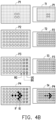
- FIG. 4B is a schematic view of a projection position guiding method corresponding to FIG. 4A according to an embodiment of the present disclosure.
- the projection system 10 determines whether the projection position guiding function is activated, and if so, proceeds to step S420, otherwise step S410 is repeated.
- the projector 110 projects the initial projection content onto the projection target 130 to generate an initial projection image P1.
- the initial projection content shown in the projection image P1 includes a plurality of initial positioning grid points arranged at intervals. It should be noted that FIG. 4A and FIG.
- the image capturing device 120 captures the projection target 130 to generate the initial captured image T1, and the initial captured image T1 includes at least part of the initial projection image P1.
- step S430 the projection system 10 determines whether the plurality of initial positioning grid points satisfy a plurality of recognizable conditions according to the initial projection image P1 in the initial captured image T1.
- the recognizable conditions are as described above and will not be repeated here.
- the process goes to step S440, and when the plurality of initial positioning grid points do not satisfy at least one of the plurality of recognizable conditions, the process goes to step S480.
- step S480 the projection system 10 stops the projection position guiding function.
- the projector 110 stops projecting the initial positioning grid point and the image capturing device 120 stop capturing images.
- step S490 the projection system 10 provides other adjustment instructions.
- text may be displayed on the display screen (projection target) by the projector 110 to provide an environment adjustment method to satisfy the multiple recognizable conditions, such as suggesting the user to improve the poor environment for the projection target 130.
- the projection system 10 converts the coordinate system of the projector 110 and the coordinate system of the image capturing device 120 to project the projection content onto the projection target 130 to generate a projection image P2, and the projection content P2 includes a plurality of positioning grid points arranged at intervals.
- the projection system 10 may convert the coordinate system of the projector 110 and the coordinate system of the image capturing device 120 according to the positions of the multiple initial positioning grid points in the captured image T1, so as to estimate the positions of the multiple positioning grid points of the projection content P2.
- the number of positioning grid points in the projection content is greater than the number of initial positioning grid points in the initial projection content
- the number of positioning grid points in the projection image P2 is greater than the number of initial positioning grid points in the projection image P1.
- the image capturing device 120 captures the projection target 130 to generate a captured image T2, and the captured image T2 includes at least part of the projection image P2.
- step S450 the projection system 10 determines whether the positioning grid points in the captured image P2 include at least one unrecognizable grid point.
- the process goes to step S460.
- the projection system 10 determines that the captured image 2 does not have any unrecognizable grid point, the process returns to step S410.
- step S460 after comparing the projection content projected by the projector 110 with the projection image P2 in the captured image T2, it may be determined that the multiple positioning grid points in the captured image T2 are not completely captured and do not satisfy the fifth recognizable condition, that is, it can be determined that the positioning grid points of the captured image T2 includes at least one unrecognizable grid point, so step S460 should be performed.
- step S460 the color of the unrecognizable grid points UG in the projection content is correspondingly changed to be the second color by the projector 110 according to the positions of the unrecognizable grid points in the captured image T2, the color of the boundary grid points BG adjacent to the unrecognizable grid points UG in the projection content is changed to be the third color, and the adjusted projection content is projected onto the projection target 130 and a projection image P3 is generated.
- the color of the positioning grid points RG excluding the unrecognizable grid points UG and the boundary grid points BG in the projection content is the first color.
- the first color, the second color, and the third color are different.
- the unrecognizable grid points UG are not completely captured in the captured image T3.
- the recognizable grid points RG include the boundary grid points BG, and the boundary grid points BG are located adjacent the unrecognizable grid points UG.
- the indicating grid points are correspondingly generated according to the distribution of the unrecognizable grid points UG and the boundary grid points BG in the projection content.
- the indicating grid points are information for adjusting the position and direction of the projector 110 or the image capturing device 120 or information for adjusting the projection environment.
- the unrecognizable grid points UG and the boundary grid points BG may serve as indicating grid points.
- the image capturing device 120 captures the projection target 130 to generate a captured image T3, and the captured image T3 includes at least part of the projection image P3.
- step S470 the projection system 10 generates an instruction image IF for adjusting the projection environment according to the distribution positions of the unrecognizable grid points UG and the boundary grid points BG in the projection content, and projects the instruction image IF onto the projection target 130 to generate the projection image P4. Moreover, the image capturing device 120 captures the projection target 130 to generate a captured image T4.
- the instruction image IF includes a plurality of indicating grid points IG, and the color (fifth color) of the plurality of indicating grid points IG is different from the color (first color) of the plurality of positioning grid points.
- the plurality of indicating grid points IG in the instruction image IF are configured to provide information for adjusting the position and direction of the projector 110 or the image capturing device 120 or adjusting the projection environment, and the instruction image IF shows in the projection image P4.
- the instruction image IF may be a direction arrow, such as a direction arrow indicating the right side in the projection content P4, to instruct the image capturing device 120 to rotate toward the right side or move to the right side, or to instruct the projector 110 to rotate toward to the left side or move to the left side, or to instruct the projection target 130 to move to the right side, etc., so as to obtain the captured image including complete projection image.
- the process returns to step S410.
- FIG. 5A is a schematic view illustrating a projection position guiding method according to an embodiment of the present disclosure.
- FIG. 5B is a schematic view of a projection position guiding method corresponding to FIG. 5A according to another embodiment of the present disclosure.
- the projection system 10 determines whether the projection position guiding function is activated, and if so, proceeds to step S520, otherwise step S510 is repeated.
- the projector 110 projects the initial projection content to the projection target 130 to generate an initial projection image P5.
- the initial projection content includes a plurality of initial positioning grid points arranged at intervals.
- the image capturing device 120 captures the projection target 130 to generate an initial captured image T5, and the initial captured image T5 includes the initial projection image P5.
- the projection system 10 determines whether the plurality of initial positioning grid points satisfy a plurality of recognizable conditions according to the initial projection image P5 in the initial captured image T5.
- the recognizable conditions are as described above and will not be repeated here.
- step S540 the projection system 10 converts the coordinate system of the projector 110 and the coordinate system of the image capturing device 120 to project the projection content to the projection target 130 to generate a projection image P6.
- the projection content includes a plurality of positioning grid points arranged at intervals.
- the projection system 10 may convert the coordinate system of the projector 110 and the coordinate system of the image capturing device 120 according to the positions of the initial positioning grid points in the captured image T5, so as to estimate the positions of the plurality of positioning grid points in the projected content.
- the number of positioning grid points in the projection content is greater than the number of initial positioning grid points in the initial projection content
- the number of positioning grid points in the projection image P6 is greater than the number of initial positioning grid points in the initial projection image P5
- the actual number and arrangement of positioning grid points are determined based on the actual design requirements and are not limited thereto.
- step S550 the projection system 10 determines whether the positioning grid points in the captured image T6 includes at leas one unrecognizable grid point.
- the process goes to step S560.
- the projection system 10 determines that the captured image T6 does not have any unrecognizable grid point, the process returns to step S520.
- step S560 since the area A1 in the captured image T6 is illuminated by a searchlight, the gray-scale contrast between the positioning grid points and the region without positioning grid points in the area A1 is less than the minimum gray-scale contrast, which does not satisfy the fourth recognizable condition, then it may be determined that the corresponding captured image T6 has unrecognizable grid points, so step S560 should be performed.
- step S560 changes the color of the unrecognizable grid points UG in the projection content is correspondingly changed to be the second color by the projector 110 according to the positions of the unrecognizable grid points in the captured image T6, the color of the boundary grid points BG adjacent to the unrecognizable grid points UG is changed to be the third color, and the adjusted projection content is projected by the projector 110 onto the projection target 130 and a projection image P7 is generated.
- the color of the recognizable grip points excluding the unrecognizable grid points UG and the boundary grid points BG is the first color, and the first color, the second color and the third color are different.
- the image capturing device 120 captures the projection target 130 to generate a captured image T7, and the captured image T7 includes the projection image P7.
- the projection system 10 may provide an environment adjustment instruction.
- the projection system 10 may provide a text message suggesting the user to turn off the searchlight or reduce the brightness of the searchlight to solve the problem that the gray-scale contrast between the positioning grid points and the region without positioning grid points in the area A1 is less than the minimum gray-scale contrast, resulting in failure to satisfy the recognizable conditions.
- the projection system 10 determines whether to stop the projection position guiding function; if so, go back to step S510, otherwise go back to step S520.
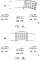
- FIG. 6A, FIG. 6B , and FIG. 6C are schematic views illustrating a projection position guiding method according to an embodiment of the present disclosure.
- a projection system 20 is configured with a projector 610A, a projector 610B, a projector 610C, an image capturing device 620A, an image capturing device 620B, an image capturing device 620C and a projection target 630.
- the projector 610A, the projector 610B, and the projector 610C respectively project the projection content with the positioning grid points to the projection target 630 in FIG. 6A, FIG. 6B , and FIG. 6C to respectively generate projection images.
- FIG. 6A, FIG. 6B , and FIG. 6C are schematic views illustrating a projection position guiding method according to an embodiment of the present disclosure.
- a projection system 20 is configured with a projector 610A, a projector 610B, a projector 610C, an image capturing device 620A, an image capturing device 620
- the projection image is located toward the right side of the projection target 630, so the positioning grid points on the right side are not completely captured, and therefore the unrecognizable grid points and the recognizable boundary grid points are shown in the projection image.
- the projection system 20 adjusts the color of the unrecognizable grid points and the color of the boundary grid points, so that the user knows that the unrecognizable grid points are projected on the right side of the projection target 630 in FIG. 6A , thereby providing the user with adjustment instruction of projection environment.
- the projection image is located in the middle of the projection target 630 so the positioning grid points are completely captured, and therefore there are no unrecognizable grid point and recognizable boundary grid point shown in the projection image.
- FIG. 6B the projection image is located in the middle of the projection target 630 so the positioning grid points are completely captured, and therefore there are no unrecognizable grid point and recognizable boundary grid point shown in the projection image.
- the projection image is located toward the left side of the projection target 630, so the positioning grid points on the left side are not completely captured, and therefore the unrecognizable grid points and the recognizable boundary grid points are shown in the projection image.
- the projection system 20 adjusts the color of the unrecognizable grid points and the color of the boundary grid points, so that the user knows that the unrecognizable grid points are projected on the left side of the projection target 630 in FIG. 6C , thereby providing the user with adjustment instruction of projection environment.
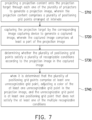
- FIG. 7 is a flowchart illustrating a projection position guiding method according to an embodiment of the present disclosure.
- the projection position guiding method is applicable to a projection system.
- the projection system includes a plurality of projectors, a plurality of image capturing devices and a projection target, and can be applied to the blending of a plurality of projection images.
- each projector projects the projection content to the projection target to generate projection image
- the projection content includes a plurality of positioning grid points arranged at intervals. It should be noted that each of the projectors projects projection content and generates the projection image onto a partial area of the projection target, and the multiple projection images projected by the multiple projectors may be blended into a blending projection image.
- step S720 the corresponding image capturing device captures the projection target to generate a captured image, and the captured image includes at least part of the projection image.
- step S730 the projection system determines whether the plurality of positioning grid points satisfy a plurality of recognizable conditions according to the projection image in the captured image.
- step S740 when the projection system determines that the plurality of positioning grid points include at least one unrecognizable grid point, the projection system adjusts the color of the at least one unrecognizable grid point in the projection content, and the at least one unrecognizable grid point is at least one of the positioning grid points that does not satisfy at least one of the plurality of recognizable conditions.
- FIG. 7 please refer to the related description of FIG. 2 , and no further description is repeated herein.
- the embodiments of the present disclosure have at least one of the following advantages or effects.
- the color of at least one unrecognizable grid point in the projection content is adjusted, so that the user may obtain the instruction for adjusting the position and direction of the image capturing device or projector from the projection image, so as to adjust the projection environment, thereby satisfying the image capturing requirement required by the projection system for performing automatic adjusting function. Therefore, there is no need to use an external device to see the adjustment instruction.
- the position of unrecognizable grid points can be clearly displayed to narrow the range for environment adjustment.
- the user may determine whether the positions or directions of the plurality of projectors and the plurality of image capturing devices need to be adjusted respectively to meet the image capturing conditions, so as to make pre-adjustment to improve the user experience.
- the term “the disclosure”, “the present disclosure” or the like does not necessarily limit the claim scope to a specific embodiment, and the reference to particularly preferred exemplary embodiments of the disclosure does not imply a limitation on the disclosure, and no such limitation is to be inferred.
- the disclosure is limited only by the scope of the appended claims. Moreover, these claims may refer to use “first”, “second”, etc. following with noun or element. Such terms should be understood as a nomenclature and should not be construed as giving the limitation on the number of the elements modified by such nomenclature unless specific number has been given.
- the abstract of the disclosure is provided to comply with the rules requiring an abstract, which will allow a searcher to quickly ascertain the subject matter of the technical disclosure of any patent issued from this disclosure.
Landscapes
- Engineering & Computer Science (AREA)
- Multimedia (AREA)
- Signal Processing (AREA)
- Physics & Mathematics (AREA)
- Geometry (AREA)
- Projection Apparatus (AREA)
- Transforming Electric Information Into Light Information (AREA)
Applications Claiming Priority (2)
| Application Number | Priority Date | Filing Date | Title |
|---|---|---|---|
| CN202210022225.1A CN116456065A (zh) | 2022-01-10 | 2022-01-10 | 投影位置指引方法 |
| EP23150946.4A EP4210326B1 (de) | 2022-01-10 | 2023-01-10 | Projektionspositionsführungsverfahren |
Related Parent Applications (2)
| Application Number | Title | Priority Date | Filing Date |
|---|---|---|---|
| EP23150946.4A Division EP4210326B1 (de) | 2022-01-10 | 2023-01-10 | Projektionspositionsführungsverfahren |
| EP23150946.4A Division-Into EP4210326B1 (de) | 2022-01-10 | 2023-01-10 | Projektionspositionsführungsverfahren |
Publications (3)
| Publication Number | Publication Date |
|---|---|
| EP4456528A2 true EP4456528A2 (de) | 2024-10-30 |
| EP4456528A3 EP4456528A3 (de) | 2025-01-01 |
| EP4456528B1 EP4456528B1 (de) | 2025-10-08 |
Family
ID=84901247
Family Applications (3)
| Application Number | Title | Priority Date | Filing Date |
|---|---|---|---|
| EP23150946.4A Active EP4210326B1 (de) | 2022-01-10 | 2023-01-10 | Projektionspositionsführungsverfahren |
| EP24199338.5A Active EP4456528B1 (de) | 2022-01-10 | 2023-01-10 | Projektionspositionsführungsverfahren |
| EP24199229.6A Active EP4451666B1 (de) | 2022-01-10 | 2023-01-10 | Projektionspositionsführungsverfahren |
Family Applications Before (1)
| Application Number | Title | Priority Date | Filing Date |
|---|---|---|---|
| EP23150946.4A Active EP4210326B1 (de) | 2022-01-10 | 2023-01-10 | Projektionspositionsführungsverfahren |
Family Applications After (1)
| Application Number | Title | Priority Date | Filing Date |
|---|---|---|---|
| EP24199229.6A Active EP4451666B1 (de) | 2022-01-10 | 2023-01-10 | Projektionspositionsführungsverfahren |
Country Status (3)
| Country | Link |
|---|---|
| US (1) | US12238462B2 (de) |
| EP (3) | EP4210326B1 (de) |
| CN (1) | CN116456065A (de) |
Citations (9)
| Publication number | Priority date | Publication date | Assignee | Title |
|---|---|---|---|---|
| US20050168705A1 (en) | 2004-02-02 | 2005-08-04 | Baoxin Li | Projection system |
| US20130141593A1 (en) | 2006-08-11 | 2013-06-06 | Geo Semiconductor Inc. | System and method for automated calibration and correction of display geometry and color |
| US20150146990A1 (en) | 2012-05-21 | 2015-05-28 | Yukinaka Uchiyama | Pattern extracting device, image projecting device, pattern extracting method, and program |
| US20150208050A1 (en) | 2014-01-21 | 2015-07-23 | Seiko Epson Corporation | Projector, display apparatus, and control method of projector |
| US20150213584A1 (en) | 2014-01-24 | 2015-07-30 | Ricoh Company, Ltd. | Projection system, image processing apparatus, and correction method |
| JP2015166893A (ja) | 2014-03-03 | 2015-09-24 | セイコーエプソン株式会社 | 位置検出装置、及び、位置検出装置の制御方法 |
| US20160353068A1 (en) | 2015-05-28 | 2016-12-01 | Masaaki Ishikawa | Projection system, image processing apparatus, and computer-readable storage medium |
| US20200213565A1 (en) | 2018-12-28 | 2020-07-02 | Coretronic Corporation | Projection system and projection method |
| US20210297643A1 (en) | 2020-03-18 | 2021-09-23 | Coretronic Corporation | Projection system and positioning method applied to projection system |
Family Cites Families (6)
| Publication number | Priority date | Publication date | Assignee | Title |
|---|---|---|---|---|
| US7942530B2 (en) * | 2006-10-31 | 2011-05-17 | The Regents Of The University Of California | Apparatus and method for self-calibrating multi-projector displays via plug and play projectors |
| EP3545676A4 (de) * | 2016-11-23 | 2021-02-17 | Réalisations Inc. Montréal | Automatisches kalibrierungsprojektionssystem und -verfahren |
| US10638104B2 (en) * | 2018-09-14 | 2020-04-28 | Christie Digital Systems Usa, Inc. | Device, system and method for generating updated camera-projector correspondences from a reduced set of test patterns |
| CN112714298B (zh) * | 2019-10-25 | 2023-06-30 | 中强光电股份有限公司 | 投影系统及其调整投影画面的方法 |
| CN114449235B (zh) * | 2020-10-30 | 2024-01-12 | 中强光电股份有限公司 | 多个投影机的画面均匀化的方法与装置 |
| JP7649715B2 (ja) * | 2021-07-30 | 2025-03-21 | 富士フイルム株式会社 | 制御装置、制御方法、投影システム、及び制御プログラム |
-
2022
- 2022-01-10 CN CN202210022225.1A patent/CN116456065A/zh active Pending
-
2023
- 2023-01-09 US US18/151,476 patent/US12238462B2/en active Active
- 2023-01-10 EP EP23150946.4A patent/EP4210326B1/de active Active
- 2023-01-10 EP EP24199338.5A patent/EP4456528B1/de active Active
- 2023-01-10 EP EP24199229.6A patent/EP4451666B1/de active Active
Patent Citations (9)
| Publication number | Priority date | Publication date | Assignee | Title |
|---|---|---|---|---|
| US20050168705A1 (en) | 2004-02-02 | 2005-08-04 | Baoxin Li | Projection system |
| US20130141593A1 (en) | 2006-08-11 | 2013-06-06 | Geo Semiconductor Inc. | System and method for automated calibration and correction of display geometry and color |
| US20150146990A1 (en) | 2012-05-21 | 2015-05-28 | Yukinaka Uchiyama | Pattern extracting device, image projecting device, pattern extracting method, and program |
| US20150208050A1 (en) | 2014-01-21 | 2015-07-23 | Seiko Epson Corporation | Projector, display apparatus, and control method of projector |
| US20150213584A1 (en) | 2014-01-24 | 2015-07-30 | Ricoh Company, Ltd. | Projection system, image processing apparatus, and correction method |
| JP2015166893A (ja) | 2014-03-03 | 2015-09-24 | セイコーエプソン株式会社 | 位置検出装置、及び、位置検出装置の制御方法 |
| US20160353068A1 (en) | 2015-05-28 | 2016-12-01 | Masaaki Ishikawa | Projection system, image processing apparatus, and computer-readable storage medium |
| US20200213565A1 (en) | 2018-12-28 | 2020-07-02 | Coretronic Corporation | Projection system and projection method |
| US20210297643A1 (en) | 2020-03-18 | 2021-09-23 | Coretronic Corporation | Projection system and positioning method applied to projection system |
Also Published As
| Publication number | Publication date |
|---|---|
| EP4451666A2 (de) | 2024-10-23 |
| EP4456528A3 (de) | 2025-01-01 |
| EP4210326A3 (de) | 2023-08-23 |
| EP4210326A2 (de) | 2023-07-12 |
| EP4456528B1 (de) | 2025-10-08 |
| US12238462B2 (en) | 2025-02-25 |
| EP4451666B1 (de) | 2025-10-08 |
| EP4210326B1 (de) | 2024-12-18 |
| US20230224443A1 (en) | 2023-07-13 |
| EP4451666A3 (de) | 2024-12-25 |
| CN116456065A (zh) | 2023-07-18 |
Similar Documents
| Publication | Publication Date | Title |
|---|---|---|
| EP3842992A1 (de) | Verfahren zur zielerkennung, schaltung, vorrichtung zur unterstützung sehbehinderter personen, elektronisches gerät und medium | |
| KR101808015B1 (ko) | 최적 문자 인식을 위한 모바일 문서 획득 지원 | |
| CN102004378B (zh) | 一种投影画面调整方法及投影装置 | |
| CN112203071A (zh) | 基于距离传感器水平校正的投影方法、系统及存储介质 | |
| EP2854400A1 (de) | Informationsverarbeitungsvorrichtung, Verfahren zur Steuerung der Informationsverarbeitungsvorrichtung und Auszeichnungsmedium | |
| JP2009031334A (ja) | プロジェクタ及びプロジェクタの投射方法 | |
| US8102560B2 (en) | Device for searching print target image adapted for printable area | |
| US10838056B1 (en) | Detection of target | |
| CN102193287A (zh) | 投影方法与投影系统 | |
| TW202018486A (zh) | 多螢幕操作方法與使用此方法的電子系統 | |
| US10481363B2 (en) | Projector and focus adjustment method | |
| US10805584B2 (en) | Projection system and image projection method | |
| CN107430841B (zh) | 信息处理设备、信息处理方法、程序以及图像显示系统 | |
| JP5311499B2 (ja) | 画像処理装置およびそのプログラム | |
| EP4456528B1 (de) | Projektionspositionsführungsverfahren | |
| US20030011566A1 (en) | Image processing apparatus, image processing method, providing medium and presentation system | |
| CN111176425A (zh) | 多屏幕操作方法与使用此方法的电子系统 | |
| US20150215495A1 (en) | Display apparatus | |
| WO2026001742A1 (zh) | 投影控制方法、装置、电子设备及计算机可读存储介质 | |
| EP4210325A1 (de) | Fokusidentifizierungsverfahren und fokusidentifizierungssystem | |
| CN113497923A (zh) | 投影系统以及用于投影系统的定位方法 | |
| US11812150B2 (en) | Imaging device performing enlargement processing based on specified area of object image, storage medium, and method of displaying object image | |
| TWI543046B (zh) | 光學觸控系統 | |
| US10455145B2 (en) | Control apparatus and control method | |
| KR102753108B1 (ko) | 목표 투사 영역을 고려하는 투사 장치 및 방법 |
Legal Events
| Date | Code | Title | Description |
|---|---|---|---|
| PUAI | Public reference made under article 153(3) epc to a published international application that has entered the european phase |
Free format text: ORIGINAL CODE: 0009012 |
|
| STAA | Information on the status of an ep patent application or granted ep patent |
Free format text: STATUS: THE APPLICATION HAS BEEN PUBLISHED |
|
| AC | Divisional application: reference to earlier application |
Ref document number: 4210326 Country of ref document: EP Kind code of ref document: P |
|
| AK | Designated contracting states |
Kind code of ref document: A2 Designated state(s): AL AT BE BG CH CY CZ DE DK EE ES FI FR GB GR HR HU IE IS IT LI LT LU LV MC ME MK MT NL NO PL PT RO RS SE SI SK SM TR |
|
| PUAL | Search report despatched |
Free format text: ORIGINAL CODE: 0009013 |
|
| STAA | Information on the status of an ep patent application or granted ep patent |
Free format text: STATUS: REQUEST FOR EXAMINATION WAS MADE |
|
| AK | Designated contracting states |
Kind code of ref document: A3 Designated state(s): AL AT BE BG CH CY CZ DE DK EE ES FI FR GB GR HR HU IE IS IT LI LT LU LV MC ME MK MT NL NO PL PT RO RS SE SI SK SM TR |
|
| RIC1 | Information provided on ipc code assigned before grant |
Ipc: H04N 9/31 20060101AFI20241126BHEP |
|
| 17P | Request for examination filed |
Effective date: 20241202 |
|
| RBV | Designated contracting states (corrected) |
Designated state(s): AL AT BE BG CH CY CZ DE DK EE ES FI FR GB GR HR HU IE IS IT LI LT LU LV MC ME MK MT NL NO PL PT RO RS SE SI SK SM TR |
|
| GRAP | Despatch of communication of intention to grant a patent |
Free format text: ORIGINAL CODE: EPIDOSNIGR1 |
|
| STAA | Information on the status of an ep patent application or granted ep patent |
Free format text: STATUS: GRANT OF PATENT IS INTENDED |
|
| INTG | Intention to grant announced |
Effective date: 20250516 |
|
| RIN1 | Information on inventor provided before grant (corrected) |
Inventor name: HSU, KANG-SHUN Inventor name: TU, HSUN-CHENG Inventor name: PENG, CHIEN-CHUN Inventor name: YANG, CHUNG-LUNG |
|
| GRAS | Grant fee paid |
Free format text: ORIGINAL CODE: EPIDOSNIGR3 |
|
| GRAA | (expected) grant |
Free format text: ORIGINAL CODE: 0009210 |
|
| STAA | Information on the status of an ep patent application or granted ep patent |
Free format text: STATUS: THE PATENT HAS BEEN GRANTED |
|
| AC | Divisional application: reference to earlier application |
Ref document number: 4210326 Country of ref document: EP Kind code of ref document: P |
|
| AK | Designated contracting states |
Kind code of ref document: B1 Designated state(s): AL AT BE BG CH CY CZ DE DK EE ES FI FR GB GR HR HU IE IS IT LI LT LU LV MC ME MK MT NL NO PL PT RO RS SE SI SK SM TR |
|
| REG | Reference to a national code |
Ref country code: GB Ref legal event code: FG4D Ref country code: CH Ref legal event code: F10 Free format text: ST27 STATUS EVENT CODE: U-0-0-F10-F00 (AS PROVIDED BY THE NATIONAL OFFICE) Effective date: 20251008 |
|
| REG | Reference to a national code |
Ref country code: DE Ref legal event code: R096 Ref document number: 602023007387 Country of ref document: DE |
|
| REG | Reference to a national code |
Ref country code: IE Ref legal event code: FG4D |
|
| REG | Reference to a national code |
Ref country code: NL Ref legal event code: MP Effective date: 20251008 |
|
| REG | Reference to a national code |
Ref country code: AT Ref legal event code: MK05 Ref document number: 1845863 Country of ref document: AT Kind code of ref document: T Effective date: 20251008 |
|
| PG25 | Lapsed in a contracting state [announced via postgrant information from national office to epo] |
Ref country code: NL Free format text: LAPSE BECAUSE OF FAILURE TO SUBMIT A TRANSLATION OF THE DESCRIPTION OR TO PAY THE FEE WITHIN THE PRESCRIBED TIME-LIMIT Effective date: 20251008 |
|
| PG25 | Lapsed in a contracting state [announced via postgrant information from national office to epo] |
Ref country code: ES Free format text: LAPSE BECAUSE OF FAILURE TO SUBMIT A TRANSLATION OF THE DESCRIPTION OR TO PAY THE FEE WITHIN THE PRESCRIBED TIME-LIMIT Effective date: 20251008 |
|
| REG | Reference to a national code |
Ref country code: LT Ref legal event code: MG9D |
|
| PG25 | Lapsed in a contracting state [announced via postgrant information from national office to epo] |
Ref country code: NO Free format text: LAPSE BECAUSE OF FAILURE TO SUBMIT A TRANSLATION OF THE DESCRIPTION OR TO PAY THE FEE WITHIN THE PRESCRIBED TIME-LIMIT Effective date: 20260108 |
|
| PGFP | Annual fee paid to national office [announced via postgrant information from national office to epo] |
Ref country code: DE Payment date: 20260130 Year of fee payment: 4 |
|
| PG25 | Lapsed in a contracting state [announced via postgrant information from national office to epo] |
Ref country code: FI Free format text: LAPSE BECAUSE OF FAILURE TO SUBMIT A TRANSLATION OF THE DESCRIPTION OR TO PAY THE FEE WITHIN THE PRESCRIBED TIME-LIMIT Effective date: 20251008 Ref country code: AT Free format text: LAPSE BECAUSE OF FAILURE TO SUBMIT A TRANSLATION OF THE DESCRIPTION OR TO PAY THE FEE WITHIN THE PRESCRIBED TIME-LIMIT Effective date: 20251008 Ref country code: HR Free format text: LAPSE BECAUSE OF FAILURE TO SUBMIT A TRANSLATION OF THE DESCRIPTION OR TO PAY THE FEE WITHIN THE PRESCRIBED TIME-LIMIT Effective date: 20251008 |
|
| PG25 | Lapsed in a contracting state [announced via postgrant information from national office to epo] |
Ref country code: RS Free format text: LAPSE BECAUSE OF FAILURE TO SUBMIT A TRANSLATION OF THE DESCRIPTION OR TO PAY THE FEE WITHIN THE PRESCRIBED TIME-LIMIT Effective date: 20260108 |
|
| PG25 | Lapsed in a contracting state [announced via postgrant information from national office to epo] |
Ref country code: IS Free format text: LAPSE BECAUSE OF FAILURE TO SUBMIT A TRANSLATION OF THE DESCRIPTION OR TO PAY THE FEE WITHIN THE PRESCRIBED TIME-LIMIT Effective date: 20260208 |
|
| PG25 | Lapsed in a contracting state [announced via postgrant information from national office to epo] |
Ref country code: PT Free format text: LAPSE BECAUSE OF FAILURE TO SUBMIT A TRANSLATION OF THE DESCRIPTION OR TO PAY THE FEE WITHIN THE PRESCRIBED TIME-LIMIT Effective date: 20260209 |
|
| PG25 | Lapsed in a contracting state [announced via postgrant information from national office to epo] |
Ref country code: PL Free format text: LAPSE BECAUSE OF FAILURE TO SUBMIT A TRANSLATION OF THE DESCRIPTION OR TO PAY THE FEE WITHIN THE PRESCRIBED TIME-LIMIT Effective date: 20251008 |
|
| PG25 | Lapsed in a contracting state [announced via postgrant information from national office to epo] |
Ref country code: LV Free format text: LAPSE BECAUSE OF FAILURE TO SUBMIT A TRANSLATION OF THE DESCRIPTION OR TO PAY THE FEE WITHIN THE PRESCRIBED TIME-LIMIT Effective date: 20251008 |
|
| PG25 | Lapsed in a contracting state [announced via postgrant information from national office to epo] |
Ref country code: BG Free format text: LAPSE BECAUSE OF FAILURE TO SUBMIT A TRANSLATION OF THE DESCRIPTION OR TO PAY THE FEE WITHIN THE PRESCRIBED TIME-LIMIT Effective date: 20251008 |