EP4456380A1 - Permanentmagnetelektromotor mit reduzierter pulsierender drehmomentwelligkeit - Google Patents
Permanentmagnetelektromotor mit reduzierter pulsierender drehmomentwelligkeit Download PDFInfo
- Publication number
- EP4456380A1 EP4456380A1 EP22909380.2A EP22909380A EP4456380A1 EP 4456380 A1 EP4456380 A1 EP 4456380A1 EP 22909380 A EP22909380 A EP 22909380A EP 4456380 A1 EP4456380 A1 EP 4456380A1
- Authority
- EP
- European Patent Office
- Prior art keywords
- permanent magnet
- side face
- trapezoid
- electric motor
- cogging torque
- Prior art date
- Legal status (The legal status is an assumption and is not a legal conclusion. Google has not performed a legal analysis and makes no representation as to the accuracy of the status listed.)
- Withdrawn
Links
Images


Classifications
-
- H—ELECTRICITY
- H02—GENERATION; CONVERSION OR DISTRIBUTION OF ELECTRIC POWER
- H02K—DYNAMO-ELECTRIC MACHINES
- H02K29/00—Motors or generators having non-mechanical commutating devices, e.g. discharge tubes or semiconductor devices
- H02K29/03—Motors or generators having non-mechanical commutating devices, e.g. discharge tubes or semiconductor devices with a magnetic circuit specially adapted for avoiding torque ripples or self-starting problems
-
- H—ELECTRICITY
- H02—GENERATION; CONVERSION OR DISTRIBUTION OF ELECTRIC POWER
- H02K—DYNAMO-ELECTRIC MACHINES
- H02K1/00—Details of the magnetic circuit
- H02K1/06—Details of the magnetic circuit characterised by the shape, form or construction
- H02K1/22—Rotating parts of the magnetic circuit
- H02K1/27—Rotor cores with permanent magnets
- H02K1/2706—Inner rotors
- H02K1/272—Inner rotors the magnetisation axis of the magnets being perpendicular to the rotor axis
- H02K1/274—Inner rotors the magnetisation axis of the magnets being perpendicular to the rotor axis the rotor consisting of two or more circumferentially positioned magnets
- H02K1/2753—Inner rotors the magnetisation axis of the magnets being perpendicular to the rotor axis the rotor consisting of two or more circumferentially positioned magnets the rotor consisting of magnets or groups of magnets arranged with alternating polarity
- H02K1/276—Magnets embedded in the magnetic core, e.g. interior permanent magnets [IPM]
- H02K1/2766—Magnets embedded in the magnetic core, e.g. interior permanent magnets [IPM] having a flux concentration effect
- H02K1/2773—Magnets embedded in the magnetic core, e.g. interior permanent magnets [IPM] having a flux concentration effect consisting of tangentially magnetized radial magnets
-
- H—ELECTRICITY
- H02—GENERATION; CONVERSION OR DISTRIBUTION OF ELECTRIC POWER
- H02K—DYNAMO-ELECTRIC MACHINES
- H02K21/00—Synchronous motors having permanent magnets; Synchronous generators having permanent magnets
- H02K21/12—Synchronous motors having permanent magnets; Synchronous generators having permanent magnets with stationary armatures and rotating magnets
- H02K21/14—Synchronous motors having permanent magnets; Synchronous generators having permanent magnets with stationary armatures and rotating magnets with magnets rotating within the armatures
- H02K21/16—Synchronous motors having permanent magnets; Synchronous generators having permanent magnets with stationary armatures and rotating magnets with magnets rotating within the armatures having annular armature cores with salient poles
-
- H—ELECTRICITY
- H02—GENERATION; CONVERSION OR DISTRIBUTION OF ELECTRIC POWER
- H02K—DYNAMO-ELECTRIC MACHINES
- H02K2213/00—Specific aspects, not otherwise provided for and not covered by codes H02K2201/00 - H02K2211/00
- H02K2213/03—Machines characterised by numerical values, ranges, mathematical expressions or similar information
Definitions
- the present disclosure relates to an electric motor, and in particular to a permanent magnet electric motor having reduced cogging torque ripples.
- the existing permanent magnet electric motors generally include a stator component, permanent magnets and a rotor component, the crosssections of the permanent magnets used are basically of a rectangular structure, the permanent magnets include N-pole permanent magnets and S-pole permanent magnets, and the N-pole permanent magnets and S-pole permanent magnets are alternately fixed in the rotor component.
- Such kind of permanent magnet electric motors has large cogging torque ripple(pulsation/fluctuation), which causes the permanent magnet electric motors to generate vibration, noise, and speed fluctuation occurs, thereby the permanent magnet electric motors cannot run smoothly, and the performance of the permanent magnet electric motors is adversely affected.
- cogging torque ripple frequency is the same with the mechanical resonance frequency of the stator or rotor, the vibration and noise generated by the cogging torque will also be amplified. Furthermore, the existence of cogging torque ripple also affects the low-speed performance in speed control systems and the high-precision positioning in position control systems of the permanent magnet electric motors.
- the technical problem to be solved by the present disclosure is to provide a permanent magnet electric motor having reduced cogging torque ripple that has smaller cogging torque ripple and vibration/noise in view of the above-mentioned shortcomings of the prior art.
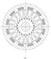
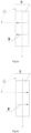
- a permanent magnet electric motor having reduced cogging torque ripple comprising a stator component, permanent magnets and a rotor component, wherein the rotor component is mounted in a center of the stator component, and an air gap is formed between an outer circumferential surface of the rotor component and an inner cambered surface of the stator component; wherein each permanent magnet has a cross-section of isosceles trapezoid, the permanent magnet is fixed in the rotor component and has a central line coinciding with a radius line of the rotor component, the magnetic lines of the permanent magnet are symmetric with reference to the central line of the permanent magnet and form included angles of 90° with a left side face of the trapezoid or a right side face of the trapezoid of the permanent magnet, and the left side face of the trapezoid and the right side face of the trapezoid of the permanent magnet respectively form included angles with the central line of the permanent magnet.
- the included angles formed by the left side face of the trapezoid and the right side face of the trapezoid of the permanent magnet with the central line of the permanent magnet are 5 to 20°, preferably 8°.
- the permanent magnets are fixed in trapezoidal slots of the rotor component.
- a top window and a bottom window are respectively provided at a top and a bottom of the trapezoidal slot of the rotor component to play a role in magnetic isolation and reduce magnetic flux leakage.
- the left side face of the trapezoid and the right side face of the trapezoid of the permanent magnet are respectively attached and fixed to a left side face and a right side face of the trapezoidal slot of the rotor component.
- the left side face of the trapezoid and the right side face of the trapezoid of the permanent magnet are respectively adhered to a left side face and a right side face of the trapezoidal slot of the rotor component through an adhesive.
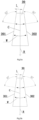
- the permanent magnet is of a split structure, is split along the central line, and is composed of a left part of the permanent magnet and a right part of the permanent magnet, which facilitates manufacturing.
- the permanent magnets include N-pole permanent magnets and S-pole permanent magnets, and the N-pole permanent magnets and the S-pole permanent magnets are alternately fixed in the rotor component.
- the present disclosure has the following advantages: by changing the shape of the permanent magnet, the magnetic force lines (magnetic lines) are symmetrically distributed with reference to the central line of the permanent magnet, to both sides of the central line, and the magnetic lines respectively form included angles of 90° with a left side face of the trapezoid or a right side face of the trapezoid of the permanent magnet, and the left side face of the trapezoid and the right side face of the trapezoid of the permanent magnet respectively form included angles with the central line of the permanent magnet, thereby reducing the cogging torque ripple of the permanent magnet motor and reducing the vibration and noise caused by the cogging torque ripple, reducing the speed fluctuation, to make the permanent magnet motor run smoothly, and improve the low-speed performance in the speed control system and the high-precision positioning in the position control system of the permanent magnet motor.
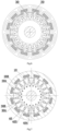
- the above-mentioned N-pole permanent magnet 20 is fixed in the trapezoidal slot of the rotor component, and the central line C of the N-pole permanent magnet is consistent with the radius line R of the rotor component.
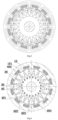
- the magnetic force lines W of the above-mentioned N-pole permanent magnet are symmetrically distributed with reference to the central line C of the N-pole permanent magnet, to both sides of the central line C, and forms included angles of 90° with the left side face and the right side face of the trapezoid of the N-pole permanent magnet respectively.
- the direction of the path of the magnetic force lines W is determined by the magnetization direction.
- the angle between the left side face 201 or the right side face 202 of the trapezoid of the N-pole permanent magnet and the central line C of the permanent magnet is L.
- the angle L is 8°.
- the magnetic line loop distribution of the S-pole permanent magnet is the same as that of the N-pole permanent magnet, except that the magnetic lines enter the rotor component from the right side face of the trapezoid of the S-pole permanent magnet and finally return to the left side face of the trapezoid of the S-pole permanent magnet.
- the present disclosure also studies the angle L between the left side face of the trapezoid/the right side face of the trapezoid and the central line C of the permanent magnet.
- the change diagram of the cogging torque ripple of the motor with time in this embodiment is shown in FIG. 11 .
- the relationship between the angle L and the cogging torque ripple of the motor is shown in Table 1. From Table 1, it can be seen that the included angle L is preferably 5 to 20°, and the best is 8°.
- FIGS. 7 to 9 it is another permanent magnet electric motor that can reduce cogging torque ripple, it has a split permanent magnet, but other structures are exactly the same as the permanent magnet electric motor in Embodiment 1.
- the permanent magnets are divided into N-pole permanent magnets and S-pole permanent magnets.
- Each N-pole permanent magnet is composed of an N-pole permanent magnet left part 20A and an N-pole permanent magnet right part 20B.
- Each S-pole permanent magnet is composed of an S-pole permanent magnet left part 30A and an S-pole permanent magnet right part 30B.
- the above-mentioned split N-pole permanent magnet may be separated along its central line and it is made up of the N-pole permanent magnet left part and the N-pole permanent magnet right part bonded together.
- the magnetizing direction of the N-pole permanent magnet left part is from the central line C to the left side face 20A1 of the trapezoid, and it forms an included angle of 90° with the left side face 20A1 of the trapezoid.
- the left side face 20A1 of the trapezoid forms an included angle L with the central line C.
- the magnetizing direction of the N-pole permanent magnet right part is from the right side face 20B1 of the trapezoid to the central line C, and it forms an included angle of 90° with the right side face of the trapezoid, and the right side face of the trapezoid forms an included angle L with the central line.
- This structure is more convenient for magnetizing the N-pole permanent magnet left part and the N-pole permanent magnet right part, as shown in FIG. 8a .
- the above-mentioned split S-pole permanent magnet 30 may be separated along its central line and it is made up of the S-pole permanent magnet left part 30A and the S-pole permanent magnet right part 30B bonded together. Except for the opposite direction of magnetization, the rest are exactly the same as the structure of the N-pole permanent magnet left part and the N-pole permanent magnet right part.
- the magnetization direction of the left part of the above-mentioned split S-pole permanent magnet is from the left side face 30A1 of the trapezoid to the central line C, and it forms an included angle of 90° with the left side face 30A1 of the trapezoid.
- the left side face 30A1 of the trapezoid forms an included angle L with the central line C.
- the magnetization direction of the right part of the S-pole permanent magnet is from the central line C to the right side face 30B1 of the trapezoid, and it forms an angle of 90° with the right side face 30B1 of the trapezoid.
- the right side face of the trapezoid forms an angle L with the central line C.
- FIG. 9 The magnetic force line distribution of the above permanent magnet electric motor is shown in FIG. 9 , which is exactly the same as that of Embodiment 1.
Landscapes
- Engineering & Computer Science (AREA)
- Power Engineering (AREA)
- Permanent Field Magnets Of Synchronous Machinery (AREA)
- Permanent Magnet Type Synchronous Machine (AREA)
Applications Claiming Priority (2)
| Application Number | Priority Date | Filing Date | Title |
|---|---|---|---|
| CN202111597968.3A CN114268181A (zh) | 2021-12-24 | 2021-12-24 | 一种能降低齿槽转矩脉动的永磁电机 |
| PCT/CN2022/117669 WO2023116057A1 (zh) | 2021-12-24 | 2022-09-07 | 一种能降低齿槽转矩脉动的永磁电机 |
Publications (2)
| Publication Number | Publication Date |
|---|---|
| EP4456380A1 true EP4456380A1 (de) | 2024-10-30 |
| EP4456380A4 EP4456380A4 (de) | 2025-07-23 |
Family
ID=80829616
Family Applications (1)
| Application Number | Title | Priority Date | Filing Date |
|---|---|---|---|
| EP22909380.2A Withdrawn EP4456380A4 (de) | 2021-12-24 | 2022-09-07 | Permanentmagnetelektromotor mit reduzierter pulsierender drehmomentwelligkeit |
Country Status (5)
| Country | Link |
|---|---|
| US (1) | US20250015695A1 (de) |
| EP (1) | EP4456380A4 (de) |
| JP (1) | JP7700380B2 (de) |
| CN (1) | CN114268181A (de) |
| WO (1) | WO2023116057A1 (de) |
Families Citing this family (2)
| Publication number | Priority date | Publication date | Assignee | Title |
|---|---|---|---|---|
| CN114268181A (zh) * | 2021-12-24 | 2022-04-01 | 宁波恒帅股份有限公司 | 一种能降低齿槽转矩脉动的永磁电机 |
| CN117318343B (zh) * | 2023-10-10 | 2024-08-23 | 淮阴工学院 | 一种具有低转矩脉动的永磁同步电机转子结构 |
Family Cites Families (18)
| Publication number | Priority date | Publication date | Assignee | Title |
|---|---|---|---|---|
| DE10084941T1 (de) | 1999-09-20 | 2002-08-14 | Ecoair Corp | Permanentmagnetischer Rotorabschnitt für elektrische Maschinen |
| US6879075B2 (en) * | 2003-01-31 | 2005-04-12 | Curtiss-Wright Electro-Mechanical Corporation | Trapezoidal shaped magnet flux intensifier motor pole arrangement for improved motor torque density |
| JP5161612B2 (ja) | 2008-02-22 | 2013-03-13 | 株式会社東芝 | 永久磁石式回転電機、永久磁石式回転電機の組立方法及び永久磁石式回転電機の分解方法 |
| CN101599665A (zh) * | 2009-06-22 | 2009-12-09 | 哈尔滨理工大学 | 一种永磁风力发电机的转子 |
| CN201656728U (zh) * | 2009-08-11 | 2010-11-24 | 西安磁林电气有限公司 | 一种多相绕组永磁无刷直流电动机及其控制电路 |
| CN102868343B (zh) * | 2012-09-20 | 2015-07-29 | 西安磁林电气有限公司 | 六相直流方波永磁无刷电机 |
| WO2014082839A2 (en) * | 2012-11-30 | 2014-06-05 | Arcelik Anonim Sirketi | A spoke permanent magnet rotor |
| DE102013212616A1 (de) * | 2013-06-28 | 2014-12-31 | Robert Bosch Gmbh | Rotor für eine elektrische Maschine, wobei an dem Rotor über seinen Umfang mehrere Rotorpole angeordnet sind |
| CN106558931B (zh) * | 2015-09-24 | 2019-12-24 | 珠海格力电器股份有限公司 | 电机及其切向式永磁转子 |
| CN106329776A (zh) * | 2016-10-13 | 2017-01-11 | 华中科技大学 | 一种内置式转子结构的永磁电机 |
| JP6939734B2 (ja) | 2017-08-01 | 2021-09-22 | 株式会社デンソー | 磁石ユニット及び回転電機駆動システム |
| CN207184193U (zh) * | 2018-01-12 | 2018-04-03 | 武汉华大新型电机科技股份有限公司 | 一种高聚磁永磁同步伺服电机的转子结构 |
| EP3579383B1 (de) * | 2018-06-07 | 2020-12-23 | maxon international ag | Drehmomentoptimierter mehrpoliger rotor für einen elektromotor |
| CN111541325B (zh) * | 2020-04-30 | 2021-11-23 | 南京理工大学 | 一种轴向磁场永磁电机组合充磁型永磁体内置式转子 |
| CN111799055B (zh) * | 2020-07-23 | 2022-04-12 | 苏州英磁新能源科技有限公司 | 一种多边形磁钢的充磁和使用方法 |
| CN113612365A (zh) * | 2021-09-08 | 2021-11-05 | 北京航空航天大学 | 一种用于直线电机的类Halbach磁极阵列结构体 |
| CN216751345U (zh) * | 2021-12-24 | 2022-06-14 | 宁波恒帅股份有限公司 | 一种能降低齿槽转矩脉动的永磁电机 |
| CN114268181A (zh) * | 2021-12-24 | 2022-04-01 | 宁波恒帅股份有限公司 | 一种能降低齿槽转矩脉动的永磁电机 |
-
2021
- 2021-12-24 CN CN202111597968.3A patent/CN114268181A/zh active Pending
-
2022
- 2022-09-07 JP JP2024529756A patent/JP7700380B2/ja active Active
- 2022-09-07 EP EP22909380.2A patent/EP4456380A4/de not_active Withdrawn
- 2022-09-07 WO PCT/CN2022/117669 patent/WO2023116057A1/zh not_active Ceased
- 2022-09-07 US US18/713,635 patent/US20250015695A1/en active Pending
Also Published As
| Publication number | Publication date |
|---|---|
| CN114268181A (zh) | 2022-04-01 |
| US20250015695A1 (en) | 2025-01-09 |
| JP7700380B2 (ja) | 2025-06-30 |
| JP2024538407A (ja) | 2024-10-18 |
| EP4456380A4 (de) | 2025-07-23 |
| WO2023116057A1 (zh) | 2023-06-29 |
Similar Documents
| Publication | Publication Date | Title |
|---|---|---|
| US8274182B2 (en) | Linear motor including extended tooth tips | |
| CN103891102B (zh) | 永久磁铁嵌入式电动机的转子、压缩机和制冷空调装置 | |
| EP4456380A1 (de) | Permanentmagnetelektromotor mit reduzierter pulsierender drehmomentwelligkeit | |
| CN109510353B (zh) | 斜极转子及永磁同步电机 | |
| US9502930B2 (en) | Motor rotor and motor having same | |
| CN111082551B (zh) | 定子及模块化结构的旋转直线两自由度永磁电机 | |
| WO2019161624A1 (zh) | 一种非对称双三相弧线永磁同步电机 | |
| CN111884456A (zh) | 转子组件和轴向磁场电机 | |
| CN114884242B (zh) | 一种高磁阻转矩的永磁电机转子冲片 | |
| CN120787403A (zh) | 电机转子及电机 | |
| CN115912706A (zh) | 一种转子结构、电机和压缩机 | |
| WO2021104123A1 (zh) | 一种电机及包括该电机的设备 | |
| CN114552925B (zh) | 一种定子永磁型轴径向混合磁场永磁磁通切换电机 | |
| CN113224878A (zh) | 一种驱动电机和电动汽车 | |
| CN216751345U (zh) | 一种能降低齿槽转矩脉动的永磁电机 | |
| CN114709949A (zh) | 一种电机转子、电机、压缩机及空调器 | |
| CN208986706U (zh) | 电动机转子、电动机及压缩机 | |
| CN219717972U (zh) | 一种永磁同步电机转子冲片 | |
| CN112003400A (zh) | 转子、电机、压缩机及空调器、车辆 | |
| JP2020512808A (ja) | モータ用ロータ、モータ及び圧縮機 | |
| CN114865877A (zh) | 一种高推力密度圆筒型横向磁通永磁直线电机 | |
| CN108039786A (zh) | 转子组件及电机 | |
| WO2023010926A1 (zh) | 大电流低压伺服电动机 | |
| CN115549332A (zh) | 电机及压缩机 | |
| CN113381578A (zh) | 一种新型模块化磁通切换无轴承电机 |
Legal Events
| Date | Code | Title | Description |
|---|---|---|---|
| STAA | Information on the status of an ep patent application or granted ep patent |
Free format text: STATUS: THE INTERNATIONAL PUBLICATION HAS BEEN MADE |
|
| PUAI | Public reference made under article 153(3) epc to a published international application that has entered the european phase |
Free format text: ORIGINAL CODE: 0009012 |
|
| STAA | Information on the status of an ep patent application or granted ep patent |
Free format text: STATUS: REQUEST FOR EXAMINATION WAS MADE |
|
| 17P | Request for examination filed |
Effective date: 20240628 |
|
| AK | Designated contracting states |
Kind code of ref document: A1 Designated state(s): AL AT BE BG CH CY CZ DE DK EE ES FI FR GB GR HR HU IE IS IT LI LT LU LV MC MK MT NL NO PL PT RO RS SE SI SK SM TR |
|
| DAV | Request for validation of the european patent (deleted) | ||
| DAX | Request for extension of the european patent (deleted) | ||
| A4 | Supplementary search report drawn up and despatched |
Effective date: 20250624 |
|
| RIC1 | Information provided on ipc code assigned before grant |
Ipc: H02K 1/276 20220101AFI20250617BHEP Ipc: H02K 29/03 20060101ALI20250617BHEP Ipc: H02K 21/16 20060101ALI20250617BHEP |
|
| STAA | Information on the status of an ep patent application or granted ep patent |
Free format text: STATUS: THE APPLICATION HAS BEEN WITHDRAWN |
|
| 18W | Application withdrawn |
Effective date: 20251124 |