EP4455767A2 - Laserbearbeitungsvorrichtung - Google Patents
Laserbearbeitungsvorrichtung Download PDFInfo
- Publication number
- EP4455767A2 EP4455767A2 EP24199902.8A EP24199902A EP4455767A2 EP 4455767 A2 EP4455767 A2 EP 4455767A2 EP 24199902 A EP24199902 A EP 24199902A EP 4455767 A2 EP4455767 A2 EP 4455767A2
- Authority
- EP
- European Patent Office
- Prior art keywords
- lens
- laser beam
- rotating
- diffraction grating
- optomechanical system
- Prior art date
- Legal status (The legal status is an assumption and is not a legal conclusion. Google has not performed a legal analysis and makes no representation as to the accuracy of the status listed.)
- Pending
Links
Images


Classifications
-
- B—PERFORMING OPERATIONS; TRANSPORTING
- B23—MACHINE TOOLS; METAL-WORKING NOT OTHERWISE PROVIDED FOR
- B23K—SOLDERING OR UNSOLDERING; WELDING; CLADDING OR PLATING BY SOLDERING OR WELDING; CUTTING BY APPLYING HEAT LOCALLY, e.g. FLAME CUTTING; WORKING BY LASER BEAM
- B23K26/00—Working by laser beam, e.g. welding, cutting or boring
- B23K26/02—Positioning or observing the workpiece, e.g. with respect to the point of impact; Aligning, aiming or focusing the laser beam
- B23K26/06—Shaping the laser beam, e.g. by masks or multi-focusing
- B23K26/062—Shaping the laser beam, e.g. by masks or multi-focusing by direct control of the laser beam
- B23K26/0622—Shaping the laser beam, e.g. by masks or multi-focusing by direct control of the laser beam by shaping pulses
- B23K26/0624—Shaping the laser beam, e.g. by masks or multi-focusing by direct control of the laser beam by shaping pulses using ultrashort pulses, i.e. pulses of 1 ns or less
-
- B—PERFORMING OPERATIONS; TRANSPORTING
- B23—MACHINE TOOLS; METAL-WORKING NOT OTHERWISE PROVIDED FOR
- B23K—SOLDERING OR UNSOLDERING; WELDING; CLADDING OR PLATING BY SOLDERING OR WELDING; CUTTING BY APPLYING HEAT LOCALLY, e.g. FLAME CUTTING; WORKING BY LASER BEAM
- B23K26/00—Working by laser beam, e.g. welding, cutting or boring
- B23K26/02—Positioning or observing the workpiece, e.g. with respect to the point of impact; Aligning, aiming or focusing the laser beam
- B23K26/06—Shaping the laser beam, e.g. by masks or multi-focusing
- B23K26/064—Shaping the laser beam, e.g. by masks or multi-focusing by means of optical elements, e.g. lenses, mirrors or prisms
- B23K26/0648—Shaping the laser beam, e.g. by masks or multi-focusing by means of optical elements, e.g. lenses, mirrors or prisms comprising lenses
-
- B—PERFORMING OPERATIONS; TRANSPORTING
- B23—MACHINE TOOLS; METAL-WORKING NOT OTHERWISE PROVIDED FOR
- B23K—SOLDERING OR UNSOLDERING; WELDING; CLADDING OR PLATING BY SOLDERING OR WELDING; CUTTING BY APPLYING HEAT LOCALLY, e.g. FLAME CUTTING; WORKING BY LASER BEAM
- B23K26/00—Working by laser beam, e.g. welding, cutting or boring
- B23K26/02—Positioning or observing the workpiece, e.g. with respect to the point of impact; Aligning, aiming or focusing the laser beam
- B23K26/06—Shaping the laser beam, e.g. by masks or multi-focusing
- B23K26/064—Shaping the laser beam, e.g. by masks or multi-focusing by means of optical elements, e.g. lenses, mirrors or prisms
- B23K26/0652—Shaping the laser beam, e.g. by masks or multi-focusing by means of optical elements, e.g. lenses, mirrors or prisms comprising prisms
-
- B—PERFORMING OPERATIONS; TRANSPORTING
- B23—MACHINE TOOLS; METAL-WORKING NOT OTHERWISE PROVIDED FOR
- B23K—SOLDERING OR UNSOLDERING; WELDING; CLADDING OR PLATING BY SOLDERING OR WELDING; CUTTING BY APPLYING HEAT LOCALLY, e.g. FLAME CUTTING; WORKING BY LASER BEAM
- B23K26/00—Working by laser beam, e.g. welding, cutting or boring
- B23K26/02—Positioning or observing the workpiece, e.g. with respect to the point of impact; Aligning, aiming or focusing the laser beam
- B23K26/06—Shaping the laser beam, e.g. by masks or multi-focusing
- B23K26/073—Shaping the laser spot
- B23K26/0734—Shaping the laser spot into an annular shape
-
- B—PERFORMING OPERATIONS; TRANSPORTING
- B23—MACHINE TOOLS; METAL-WORKING NOT OTHERWISE PROVIDED FOR
- B23K—SOLDERING OR UNSOLDERING; WELDING; CLADDING OR PLATING BY SOLDERING OR WELDING; CUTTING BY APPLYING HEAT LOCALLY, e.g. FLAME CUTTING; WORKING BY LASER BEAM
- B23K26/00—Working by laser beam, e.g. welding, cutting or boring
- B23K26/08—Devices involving relative movement between laser beam and workpiece
- B23K26/0869—Devices involving movement of the laser head in at least one axial direction
- B23K26/0876—Devices involving movement of the laser head in at least one axial direction in at least two axial directions
-
- B—PERFORMING OPERATIONS; TRANSPORTING
- B23—MACHINE TOOLS; METAL-WORKING NOT OTHERWISE PROVIDED FOR
- B23K—SOLDERING OR UNSOLDERING; WELDING; CLADDING OR PLATING BY SOLDERING OR WELDING; CUTTING BY APPLYING HEAT LOCALLY, e.g. FLAME CUTTING; WORKING BY LASER BEAM
- B23K26/00—Working by laser beam, e.g. welding, cutting or boring
- B23K26/36—Removing material
- B23K26/38—Removing material by boring or cutting
- B23K26/382—Removing material by boring or cutting by boring
- B23K26/384—Removing material by boring or cutting by boring of specially shaped holes
-
- B—PERFORMING OPERATIONS; TRANSPORTING
- B23—MACHINE TOOLS; METAL-WORKING NOT OTHERWISE PROVIDED FOR
- B23K—SOLDERING OR UNSOLDERING; WELDING; CLADDING OR PLATING BY SOLDERING OR WELDING; CUTTING BY APPLYING HEAT LOCALLY, e.g. FLAME CUTTING; WORKING BY LASER BEAM
- B23K26/00—Working by laser beam, e.g. welding, cutting or boring
- B23K26/36—Removing material
- B23K26/38—Removing material by boring or cutting
- B23K26/382—Removing material by boring or cutting by boring
- B23K26/388—Trepanning, i.e. boring by moving the beam spot about an axis
-
- G—PHYSICS
- G02—OPTICS
- G02B—OPTICAL ELEMENTS, SYSTEMS OR APPARATUS
- G02B26/00—Optical devices or arrangements for the control of light using movable or deformable optical elements
- G02B26/08—Optical devices or arrangements for the control of light using movable or deformable optical elements for controlling the direction of light
- G02B26/0808—Optical devices or arrangements for the control of light using movable or deformable optical elements for controlling the direction of light by means of one or more diffracting elements
-
- G—PHYSICS
- G02—OPTICS
- G02B—OPTICAL ELEMENTS, SYSTEMS OR APPARATUS
- G02B27/00—Optical systems or apparatus not provided for by any of the groups G02B1/00 - G02B26/00, G02B30/00
- G02B27/42—Diffraction optics, i.e. systems including a diffractive element being designed for providing a diffractive effect
- G02B27/4233—Diffraction optics, i.e. systems including a diffractive element being designed for providing a diffractive effect having a diffractive element [DOE] contributing to a non-imaging application
Definitions
- the present invention relates to a laser machining device.
- it covers a picosecond or femtosecond pulsed laser machining device comprising an optical trepanning head.
- Laser spots whose diameter corresponds to the diameter of the holes to be machined, are commonly used. However, this approach does not allow control of the clearance angles.
- optical trepanning involves a circular movement of the laser beam around the circumference of the hole to be machined.
- the divergence of the laser beam on the surface of the workpiece in this case causes a clearance angle that must be compensated for by changing the incidence of the laser beam.
- trepanning heads have galvanometric mirror trains that allow the laser beam to be oriented on the workpiece.
- Other systems use rotating focusing optics based on prisms, such as Dove prisms, wedge prisms, or Abbe-Koenig prisms for example.
- refractive optical components such as prisms
- Their bulkiness also hinders the movements of these optical trepanning heads.
- the present invention provides a compact optical trepanning device that can be easily oriented along several axes, so as to control the clearance angles of the machined part.
- positive or negative clearance angles can be obtained with great precision, whatever the shape to be machined.
- An objective of the present invention is to provide a micromachining solution particularly suitable for profiles with a high height/diameter ratio.
- the present invention is particularly suitable for machining parts where the height/diameter ratio is greater than 2, or even greater than 3 or 5.
- High-precision mechanical parts such as injectors or spinning nozzles can then be machined. Holes with a diameter of between 50 micrometers and 1 millimeter can be machined using the present invention.
- Another objective of the present invention is to provide a solution adaptable to a wide variety of materials, particularly in relation to their thermal diffusion properties.
- the rotating device of the optomechanical system comprises a rotating diffraction grating, which may be of circular geometry.
- the thickness of the rotating diffraction grating is less than or equal to 1 millimeter.
- the diffractions of order 1 and -1 are mainly exploited through the rotating diffraction grating.
- the rotating device according to the invention may be a commercially available spindle, the rotation speed of which is greater than 180,000 revolutions per minute, or even 200,000 revolutions per minute.
- the optomechanical system of the device advantageously comprises a first lens, arranged between the laser source and the rotating device, the focal length of which can be variable.
- the optomechanical system can further comprise a second lens, arranged downstream of the rotating device and movable in translation along the longitudinal axis of the optomechanical system.
- the second lens can be conical.
- the optomechanical system can further comprise a last lens the focal length of which is fixed.
- the last lens of the optomechanical system has the role of a focusing lens. Between the second lens and the last lens, one or more other lenses can be arranged and possibly form a train of lenses.
- the present invention also relates to a method of machining by optical trepanation.
- the present invention relates for example to a trepanning head 1 comprising an opto-mechanical system 2 and a laser source 3 as illustrated in figure 1 .
- the optomechanical system 2 is connected to the laser source 3 by one or more optical fibers 4.
- the optical fiber 4 conducts the laser beam FL from the laser source 3 to the optomechanical system 2, to which it is connected by means of an optical connection 41.
- the optical fiber(s) 4 are preferably hollow and adapted to the light power of the laser source 3.
- the laser source 3 is preferably fixed. It is of the picolaser or femtolaser type.
- the optical trepanning head 1 is movable along one of the axes x, y, or z, preferably along the two horizontal axes x and y.
- the device also comprises a support S intended to hold the part P to be drilled or machined.
- the support S can be arranged horizontally in a fixed manner.
- the optical trepanning head 1, movable along the axes x and y, can then move on the surface of the part P and perform the drilling at the predetermined locations.
- Each drilling operation can also require a movement of the trepanning head 1 along the two axes x and y, allowing a circular movement of the trepanning head 1.
- the optical trepanning head 1 can be fixed and the support S can be mounted mobile along the two axes x and y so as to allow a rotational movement.
- the optical trepanning head 1 or the holder S, or both, can be additionally mounted so as to be movable along the z axis. Workpieces of varying thickness and shape can then be machined.
- the support S or the optical trepanning head 1, or both can further be mounted to be movable in rotation about at least one horizontal axis, such as x, or y, or both. In this way, the machining can be carried out at angles of incidence different from the right angle with respect to the surface of the part P.
- the laser source 3 is a picosecond or femtosecond pulsed laser source. Such sources deliver a laser beam in pulses of less than ten picoseconds, preferably less than 100 femtoseconds, or even less than 10 femtoseconds. Different picosecond and femtosecond laser sources are commercially available and known to those skilled in the art. Optical powers greater than 30 W, preferably equal to or greater than 50 W, are advantageously used. The energy of each pulse is greater than 100 microjoules, preferably greater than 500 microjoules.
- the advantage of such a pulsed light source is to limit the energy useful for machining to the point of impact of the FL laser beam, avoiding heat transfer to neighboring areas.
- the material surrounding the impact of the FL laser beam is therefore not damaged, which allows high quality drilling and machining, as well as a wide variety of materials that can be machined.
- the optomechanical system 2 comprises a head body 21, in which the various optomechanical elements are assembled.
- the head body 21 comprises a central space allowing the passage of a laser beam FL and its guidance through the optomechanical elements contained in the optomechanical system 2, from the optical fiber(s) 4 to its impact on the part P to be machined.
- Several optomechanical elements are arranged on the path of the laser beam FL between the connection of the optical fiber 41 and the end 26, opposite the connection of the optical fiber, of the head body 21.
- the optomechanical system 2 thus comprises a longitudinal axis corresponding overall to the path of the laser beam FL.
- the head body 21 comprises a first lens L1, a pin 22 containing a rotating diffraction grating R1, a second lens L2 and a last lens L3.
- the last lens L3 is arranged at the end 26 of the head body 21.
- the laser beam FL from the optical fiber 4 passes through the first lens L1, then the pin 22, then through the second L2 and last L3 lenses.
- the arrangement of the first L1, second L2, and last L3 lenses is such that the second lens L2 is downstream of the first lens L1 and upstream of the last lens L3.
- upstream and downstream are defined throughout the text in relation to the direction of propagation of the FL laser beam. Any element located upstream of another element will be impacted by the FL laser beam before it. Any element located downstream of another element will be impacted by the FL laser beam after it.
- the first L1, second L2 and last L3 lenses aim to converge the laser beam FL into concentrated points so as to focus its energy.
- the focal length of each of the first L1, second L2 and last L3 lenses can be predetermined or variable.
- each of the first L1, second L2 and last L3 lenses relative to each other may be predetermined or variable.
- Each of the lenses may be arranged inside the head body 21 on lens supports which may be fixed or movable.
- a lens support may be movable in translation along the path of the laser beam FL or in rotation along one or more of the x or y axes, so as to vary the direction of the path of the laser beam FL.
- the movable lens supports may be motorized and controlled according to the intended objectives. They allow precise adjustments of the laser beam FL and its impact on the workpiece P.
- One or more intermediate lenses may be provided between the second L2 and last L3 lenses. They may be independently of each other fixed or movable in translation along the path of the laser beam FL, or in rotation along one or more of the x or y axes.
- the first lens L1 is a variable focal length lens.
- the position of the focal plane PL1 corresponding to the focal length of the first lens L1 can therefore be modified, either before the machining operation or during the machining operation.
- a lens allowing easy and rapid variation of its focal length is therefore advantageously used.
- a liquid lens such as those developed by the company Varioptic and described in the patents EP 1870742 , EP1662276 , WO2007113637 can be used for this purpose.
- the focusing speed of the lens allows almost instantaneous adjustment of the focusing plane.
- the laser beam FL then passes through the rotating diffraction grating R1 contained in the pin 22.
- the rotating diffraction grating R1 is the only rotating opto-mechanical element of the opto-mechanical system 2.
- the rotating diffraction grating R1 is illustrated in figure 3 . It allows to deflect the light of the FL laser beam in predefined directions, known as diffraction orders.
- Commercially available R1 rotating diffraction gratings can be used.
- phase grating type R1 rotating diffraction gratings known for their excellent diffraction efficiency, can be used.
- the diffraction grating is preferably a phase grating, the relief of which is either continuous (e.g. sinusoidal) or composed of a limited number of height levels (binary or multi-level).
- the diffraction orders +1 and -1 will be exploited, and the geometry of the phase grating must make it possible to obtain maximum diffraction efficiency in these two orders.
- other grating geometries making it possible to exploit the higher diffraction orders can be used.
- the rotating diffraction grating R1 is a very compact component. It can be composed, for example, of a network of lines, of micrometric size on a glass plate with a thickness of less than 1 mm.
- the rotating diffraction grating R1 is circularly symmetrical and lightweight. It can therefore be advantageously associated with an ultra-high-speed spindle 22. Such a spindle can rotate at a speed of the order of 180,000 revolutions per minute, 200,000 revolutions per minute, 300,000 revolutions per minute or more.
- the characteristics of the rotating diffraction grating R1 allow optimum balancing of the spindle 22 during its rotation.
- the reduced size of the rotating diffraction grating R1 makes it possible to reduce the size of the spindle 22 and to attenuate any defects.
- the rotating diffraction grating R1 Since the rotating diffraction grating R1 is very thin, the impact of a possible angular shift will be significantly attenuated compared to other arrangements incorporating prisms or mirrors. In particular, an angular shift of the rotating diffraction grating R1 of up to 30 mrad can be tolerated in the device according to the present invention.
- the spindle 22 is designed to rotate at a speed greater than 180,000 revolutions per minute, preferably greater than 300,000 revolutions per minute and more advantageously greater than 500,000 revolutions per minute. It may be, for example, an industrial micro-drilling spindle such as the MUHD spindle rotating at 500,000 revolutions per minute with a drilling rate of 21 Hz. It may alternatively be a micro-gas turbine. An example of spindles 22 based on a combination of hybrid aerodynamic/aerostatic bearings, described in the patent application CH 710 120 , may be used for this purpose. Other spindles intended for example for micromachining may be used within the scope of the present invention.
- the second lens L2 is of the conical type, making it possible to shape the laser beam FL into the shape of rings or a hollow cylinder.
- the second lens L2 may in particular be of the “axicon” type.
- the second lens L2 is preferably mounted on a movable lens support (not shown) in translation along the head body 1. In other words, the second lens L2 is movable along the longitudinal axis of the optomechanical system 2.
- the laser beam FL from the rotating diffraction grating R1 passes through the second lens L2, designed to produce a laser beam in the shape of a ring or hollow cylinder.
- the vertical displacement of the second lens L2 over a distance d1 makes it possible to modulate the distance D which separates it from the last lens L3.
- the second lens L2 may be conical in shape.
- the tip of the cone of such a lens depending on its properties and the needs of the device, may be oriented towards the laser source or towards the last lens L3.
- the second lens L2 may comprise a set of several lenses.
- the last lens L3 is preferably mounted on a fixed support between the second lens L2 and the end 26 of the head body 21.
- the focal length of the last lens L3 is preferably predetermined.
- the last lens L3 is preferably converging.
- the focal length of the first lens L1 and the position of the second lens L2 can be varied, either in terms of pre-settings before the micromachining operation or during machining.
- the focal length and the position of the first lens L1 and the position of the second lens L2 can be modulated, either in terms of presets before the machining operation, or during machining.
- the impact of the laser beam FL on the part P to be machined can take the form of a single point with a diameter of the order of 20 micrometers.
- the impact of the laser beam FL, when the spindle 22 is not rotating can take the form of two points with a diameter of the order of 20 micrometers.
- the spacing of the two light points on the surface of the workpiece P to be machined depends in particular on the position of the second lens L2.
- the optical trepanning head 1 has the advantage of being compact.
- the opto-mechanical system 2 of the optical trepanning head 1 has a footprint smaller than a cylinder 50 mm in diameter and 200 mm in length. The trepanning head can then easily be mounted on translation and rotation axes.
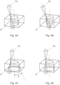
- the clearance angles A can be positive, as illustrated in Figures 4A and 4B , or negative, as illustrated in Figures 4C and 4D .
- a negative draft angle A of 0° to 5° can be achieved.
- the present invention also relates to a method of machining by optical trepanning making it possible to control the clearance angles A of a part P being machined.
- the clearance angle A may be straight, as shown in Figure 4A for example.
- the edges of the hole in the machined part P are perpendicular to its outer surface.
- the hole is cylindrical.
- the clearance angle A can be positive, as shown in Figure 4B .
- the hole forms in the machined part P a conical section where the diameter of the upper surface is greater than the diameter on the lower surface of the part P.
- the upper surface of the part P is understood as the surface on which the laser beam FL is incident.
- the lower surface of the part P is the opposite surface, which rests on the support S.
- the clearance angle A can be negative, as shown in Figures 4C and 4D .
- the hole forms in the machined part P a conical section where the diameter of the upper surface is less than the diameter on the lower surface of the part P.
- the clearance angle A is not directly representative of the angle of incidence of the laser beam FL on the upper surface of the part P.
- An incidence of the laser beam orthogonal to the upper surface of the part P does not produce a right clearance angle A , but a negative clearance angle A , as shown in figure 4D .
- the right clearance angle A is obtained by means of an inclined incidence of the laser beam FL on the surface upper part of the part P to be machined, as shown in Figure 4A .
- the incidence of the laser beam FL on the upper surface of the workpiece P must be positive, i.e., oriented toward the inside of the hole being machined.
- the clearance angle A becomes positive, as shown in Figure 4B .
- the incident angle of the laser beam FL on the upper surface of the workpiece P is negative, as shown in Figure 4C , the clearance angle A becomes negative.
- the method comprises a step of focusing a picosecond or femtosecond pulsed laser beam FL on the part P to be machined.
- the laser beam FL is in particular focused on the part P by means of the optical trepanning head 1 described above.
- the method comprises a step of initiating a precessional movement of the laser beam FL by means of a rotating diffraction grating R1.
- the rotational speed of the rotating diffraction grating R1 is 180,000 revolutions per minute or more.
- the rotational speed of the rotating diffraction grating R1 can be adapted to the pulse frequency of the laser beam FL and to the machining requirements, in particular to the diameter of the hole to be machined in the workpiece P. An increased rotational speed allows faster machining.
- the rotating diffraction grating R1 can in particular be integrated into a spindle 22 as described above.
- the precessional movement of the laser beam FL allows the laser beam FL to form a circle of given diameter on the upper surface of the workpiece P.
- the method according to the present invention comprises a step of modulating the distance of the second lens L2 movable in translation, relative to the rotating diffraction grating R1.
- the second lens L2 can be movable over a distance d1.
- the distance D separating the second lens L2 and the last lens L3 can then vary from a minimum distance Dm to a maximum distance DM.
- the minimum distances Dm and maximum distances DM, as well as the distance d1 are adaptable according to the properties of the second lens L2, in particular according to the diffraction angle and the deviation angle which characterize the second lens L2.
- the distance separating the second lens L2 from the rotating diffraction grating R1 makes it possible to modulate the distance separating the two laser beams at the output of the second lens L2, generated for example by the +1/-1 diffraction orders of the rotating diffraction grating R1. Downstream of the lens L3, the angle of incidence of the laser beams resulting from these +1/-1 diffraction orders, on the workpiece P, is then adaptable.
- the laser beams FL resulting from the +1/-1 diffraction orders can focus on the surface of the workpiece P at a point with diameters between 10 microns and 20 microns.
- the incidence orthogonal to the surface of the workpiece produces a negative clearance angle A.
- the laser beams FL resulting from the diffraction orders +1/-1 have a positive incidence on the upper surface of the workpiece P, thus forming a right or positive clearance angle A.
- the laser beams FL resulting from the diffraction orders +1/-1 have a negative incidence on the upper surface of the workpiece P, thus forming a negative clearance angle A.
- Focusing of laser beams resulting from diffraction can be applied to diffraction orders other than +1 and -1.
- laser beams resulting from diffraction of higher orders can be focused onto the surface of the workpiece.
- the rotating device (22) of the optomechanical system (2) comprises a rotating diffraction grating (R1).
- the rotating diffraction grating (R1) has circular geometry.
- the rotating diffraction grating (R1) has a thickness of less than 1 millimeter.
- the rotating diffraction grating (R1) is of the phase grating type.
- the rotating device (22) is a spindle whose rotation speed is greater than 180,000 revolutions per minute.
- the first lens (L1) is arranged between the laser source (3) and the rotating device (22) and its focal length is variable.
- the second lens (L2) is arranged downstream of the rotating device (22) and is movable in translation along the longitudinal axis of the opto-mechanical system (2).
- the second lens (L2) is conical.
- the optomechanical system comprises a final lens (L3), arranged at the end (26) of the head body (21) whose focal length is fixed.
Landscapes
- Physics & Mathematics (AREA)
- Optics & Photonics (AREA)
- Engineering & Computer Science (AREA)
- Plasma & Fusion (AREA)
- Mechanical Engineering (AREA)
- General Physics & Mathematics (AREA)
- Laser Beam Processing (AREA)
- Organic Low-Molecular-Weight Compounds And Preparation Thereof (AREA)
- Optical Couplings Of Light Guides (AREA)
- Diffracting Gratings Or Hologram Optical Elements (AREA)
Applications Claiming Priority (3)
| Application Number | Priority Date | Filing Date | Title |
|---|---|---|---|
| CH01087/19A CH716546A1 (fr) | 2019-08-29 | 2019-08-29 | Dispositif d'usinage laser et procédé de trépanation optique. |
| PCT/IB2020/057953 WO2021038453A1 (fr) | 2019-08-29 | 2020-08-26 | Dispositif d'usinage laser |
| EP20761912.3A EP4021677B1 (de) | 2019-08-29 | 2020-08-26 | Laserbearbeitungsvorrichtung |
Related Parent Applications (1)
| Application Number | Title | Priority Date | Filing Date |
|---|---|---|---|
| EP20761912.3A Division EP4021677B1 (de) | 2019-08-29 | 2020-08-26 | Laserbearbeitungsvorrichtung |
Publications (2)
| Publication Number | Publication Date |
|---|---|
| EP4455767A2 true EP4455767A2 (de) | 2024-10-30 |
| EP4455767A3 EP4455767A3 (de) | 2025-04-23 |
Family
ID=68807950
Family Applications (2)
| Application Number | Title | Priority Date | Filing Date |
|---|---|---|---|
| EP24199902.8A Pending EP4455767A3 (de) | 2019-08-29 | 2020-08-26 | Laserbearbeitungsvorrichtung |
| EP20761912.3A Active EP4021677B1 (de) | 2019-08-29 | 2020-08-26 | Laserbearbeitungsvorrichtung |
Family Applications After (1)
| Application Number | Title | Priority Date | Filing Date |
|---|---|---|---|
| EP20761912.3A Active EP4021677B1 (de) | 2019-08-29 | 2020-08-26 | Laserbearbeitungsvorrichtung |
Country Status (6)
| Country | Link |
|---|---|
| US (1) | US20220305590A1 (de) |
| EP (2) | EP4455767A3 (de) |
| JP (1) | JP7452901B2 (de) |
| CH (1) | CH716546A1 (de) |
| LT (1) | LT4021677T (de) |
| WO (1) | WO2021038453A1 (de) |
Families Citing this family (3)
| Publication number | Priority date | Publication date | Assignee | Title |
|---|---|---|---|---|
| EP4132739A1 (de) * | 2020-04-10 | 2023-02-15 | Rolex Sa | Laserdrehsystem, laserdrehverfahren mit solch einem system und durch solch ein verfahren erhaltenes teil |
| GB202207505D0 (en) | 2022-05-23 | 2022-07-06 | Rolls Royce Plc | System for use with component of power generation apparatus |
| DE102024001157B4 (de) * | 2024-04-11 | 2025-09-04 | Mercedes-Benz Group AG | Verfahren zur Formung eines Laserstrahles für eine Materialbearbeitung |
Citations (4)
| Publication number | Priority date | Publication date | Assignee | Title |
|---|---|---|---|---|
| EP1662276A1 (de) | 2004-11-24 | 2006-05-31 | Varioptic | Linse mit veränderbarer Brennweite |
| WO2007113637A1 (en) | 2006-03-31 | 2007-10-11 | Varioptic | Multi-phase liquid composition and optical lens driven by electrowetting |
| EP1870742A1 (de) | 2006-06-21 | 2007-12-26 | Varioptic | Dreifache Flüssiglinse |
| CH710120A1 (fr) | 2014-09-02 | 2016-03-15 | Posalux Sa | Broche à paliers aérostatiques et aérodynamiques. |
Family Cites Families (14)
| Publication number | Priority date | Publication date | Assignee | Title |
|---|---|---|---|---|
| DE19736110C2 (de) * | 1997-08-21 | 2001-03-01 | Hannover Laser Zentrum | Verfahren und Vorrichtung zur grat- und schmelzfreien Mikrobearbeitung von Werkstücken |
| US6791060B2 (en) * | 1999-05-28 | 2004-09-14 | Electro Scientific Industries, Inc. | Beam shaping and projection imaging with solid state UV gaussian beam to form vias |
| JP4069348B2 (ja) | 2001-02-22 | 2008-04-02 | トヨタ自動車株式会社 | レーザ加工方法およびレーザ加工装置 |
| US6804269B2 (en) | 2001-06-19 | 2004-10-12 | Hitachi Via Mechanics, Ltd. | Laser beam delivery system with trepanning module |
| JP2003305585A (ja) * | 2001-09-11 | 2003-10-28 | Seiko Epson Corp | レーザー加工方法および加工装置 |
| WO2006116722A2 (en) * | 2005-04-28 | 2006-11-02 | The Pennsylvania State Research Foundation | Apparatus and method for conducting laser stir welding |
| JP4386137B2 (ja) | 2008-02-29 | 2009-12-16 | トヨタ自動車株式会社 | レーザ加工装置及びレーザ加工方法 |
| JP6084358B2 (ja) | 2011-11-24 | 2017-02-22 | 三星ダイヤモンド工業株式会社 | レーザ加工方法及びレーザ加工装置 |
| US9931712B2 (en) * | 2012-01-11 | 2018-04-03 | Pim Snow Leopard Inc. | Laser drilling and trepanning device |
| JP5908009B2 (ja) | 2013-08-20 | 2016-04-26 | 三菱重工業株式会社 | レーザ加工方法及びレーザ加工装置 |
| FR3012059B1 (fr) * | 2013-10-17 | 2016-01-08 | Centre Nat Rech Scient | Methode et dispositif de micro-usinage par laser |
| US9690085B2 (en) * | 2014-01-30 | 2017-06-27 | Olympus Corporation | Microscope illumination apparatus, microscope, and microscope illumination method |
| EP3184232B1 (de) | 2015-12-23 | 2025-05-28 | Universität Stuttgart | Bohrvorrichtung, verfahren und verwendung |
| JP2020040072A (ja) * | 2018-09-06 | 2020-03-19 | 日本電信電話株式会社 | レーザー加工装置 |
-
2019
- 2019-08-29 CH CH01087/19A patent/CH716546A1/fr unknown
-
2020
- 2020-08-26 JP JP2022512740A patent/JP7452901B2/ja active Active
- 2020-08-26 EP EP24199902.8A patent/EP4455767A3/de active Pending
- 2020-08-26 WO PCT/IB2020/057953 patent/WO2021038453A1/fr not_active Ceased
- 2020-08-26 LT LTEPPCT/IB2020/057953T patent/LT4021677T/lt unknown
- 2020-08-26 EP EP20761912.3A patent/EP4021677B1/de active Active
- 2020-08-26 US US17/638,711 patent/US20220305590A1/en active Pending
Patent Citations (4)
| Publication number | Priority date | Publication date | Assignee | Title |
|---|---|---|---|---|
| EP1662276A1 (de) | 2004-11-24 | 2006-05-31 | Varioptic | Linse mit veränderbarer Brennweite |
| WO2007113637A1 (en) | 2006-03-31 | 2007-10-11 | Varioptic | Multi-phase liquid composition and optical lens driven by electrowetting |
| EP1870742A1 (de) | 2006-06-21 | 2007-12-26 | Varioptic | Dreifache Flüssiglinse |
| CH710120A1 (fr) | 2014-09-02 | 2016-03-15 | Posalux Sa | Broche à paliers aérostatiques et aérodynamiques. |
Also Published As
| Publication number | Publication date |
|---|---|
| JP2022547412A (ja) | 2022-11-14 |
| EP4021677B1 (de) | 2024-10-02 |
| LT4021677T (lt) | 2024-12-27 |
| EP4455767A3 (de) | 2025-04-23 |
| JP7452901B2 (ja) | 2024-03-19 |
| WO2021038453A1 (fr) | 2021-03-04 |
| CH716546A1 (fr) | 2021-03-15 |
| EP4021677A1 (de) | 2022-07-06 |
| US20220305590A1 (en) | 2022-09-29 |
Similar Documents
| Publication | Publication Date | Title |
|---|---|---|
| EP4021677B1 (de) | Laserbearbeitungsvorrichtung | |
| EP2334465B1 (de) | Laserschneidverfahren und einrichtung mit mitteln zum modifizieren des laserstrahlqualitätsfaktors durch eine diffraktive optische komponente | |
| EP2576127B2 (de) | Verfahren zum Eingravieren von mindestens einer Kerbe als Bruchansätze unter Verwendung einer Anlage zur Laserbearbeitung mit optischen Fasern | |
| EP3352974B1 (de) | System und verfahren zur generativen fertigung durch laserschmelzen eines pulverbetts | |
| FR2644900A1 (fr) | Support de fibres multiples pour coupleur de sortie, et son procede d'utilisation | |
| EP0112224A1 (de) | Vorrichtung zum Heizen einer ringförmigen Oberfläche eines faserförmigen Gegenstandes | |
| FR2747802A1 (fr) | Microdispositif optomecanique, et application a un microdeflecteur optomecanique | |
| FR2627599A1 (fr) | Systeme optique pour le percage de trous au moyen d'un faisceau laser | |
| CA2775983A1 (fr) | Dispositif de transmission d'energie lumineuse et procede de transmission associe | |
| CN101965243A (zh) | 激光加工装置以及激光加工方法 | |
| WO2019207239A1 (fr) | Appareil et procédé pour fabriquer un objet tridimensionnel | |
| FR2977513A1 (fr) | Procede de coupage laser a fibre ou disque avec distribution d'intensite du faisceau laser en anneau | |
| EP2117764B1 (de) | Verfahren zum schneiden von zu verarbeitenden teilen mittels eines gepulsten lasers | |
| WO2021205030A1 (fr) | Système de tournage laser, procédé de tournage laser utilisant une tel système, et composant obtenu par un tel procédé | |
| EP3645207A1 (de) | Verfahren zur strukturierung eines substrats, anordnung mit einem substrat und vorrichtung zur strukturierung des substrats und substrat mit einer solchen struktur | |
| EP0038297B1 (de) | Verfahren zum Entgräten eines scharfen Instruments, Ausführung des Verfahrens und durch dieses Verfahren erhaltenes scharfes Instrument | |
| EP0429368A1 (de) | Vorrichtung zur Scharfeinstellung eines Lichtbündels, die erlaubt einen Brennpunktfleck länglicher Form zu erhalten | |
| EP3295229A2 (de) | Laserbehandlungsvorrichtung und arbeitsstation mit einer derartigen vorrichtung | |
| EP4543617B1 (de) | Optische vorrichtung zum abtasten eines lichtstrahls über ein zu bearbeitendes werkstück | |
| WO2016024069A1 (fr) | Dispositif d'usinage par faisceau laser d'un trou a conicite controlée avec un module afocal déplaçable | |
| FR2961731A1 (fr) | Procede et installation de coupage laser a fibre ou disque avec distribution d'intensite du faisceau laser en anneau | |
| EP4132740A1 (de) | Laserdrehsystem, laserdrehverfahren und durch verwendung solch eines systems erhaltenes teil | |
| FR2990522A1 (fr) | Systeme optique de deflexion | |
| WO2012069707A1 (fr) | Système réfléchissant |
Legal Events
| Date | Code | Title | Description |
|---|---|---|---|
| PUAI | Public reference made under article 153(3) epc to a published international application that has entered the european phase |
Free format text: ORIGINAL CODE: 0009012 |
|
| STAA | Information on the status of an ep patent application or granted ep patent |
Free format text: STATUS: THE APPLICATION HAS BEEN PUBLISHED |
|
| AC | Divisional application: reference to earlier application |
Ref document number: 4021677 Country of ref document: EP Kind code of ref document: P |
|
| AK | Designated contracting states |
Kind code of ref document: A2 Designated state(s): AL AT BE BG CH CY CZ DE DK EE ES FI FR GB GR HR HU IE IS IT LI LT LU LV MC MK MT NL NO PL PT RO RS SE SI SK SM TR |
|
| REG | Reference to a national code |
Ref country code: DE Ref legal event code: R079 Free format text: PREVIOUS MAIN CLASS: G02B0027420000 Ipc: B23K0026062200 |
|
| PUAL | Search report despatched |
Free format text: ORIGINAL CODE: 0009013 |
|
| AK | Designated contracting states |
Kind code of ref document: A3 Designated state(s): AL AT BE BG CH CY CZ DE DK EE ES FI FR GB GR HR HU IE IS IT LI LT LU LV MC MK MT NL NO PL PT RO RS SE SI SK SM TR |
|
| RIC1 | Information provided on ipc code assigned before grant |
Ipc: G02B 27/42 20060101ALI20250317BHEP Ipc: G02B 27/09 20060101ALI20250317BHEP Ipc: B23K 26/384 20140101ALI20250317BHEP Ipc: B23K 26/073 20060101ALI20250317BHEP Ipc: B23K 26/388 20140101ALI20250317BHEP Ipc: B23K 26/06 20140101ALI20250317BHEP Ipc: B23K 26/0622 20140101AFI20250317BHEP |
|
| STAA | Information on the status of an ep patent application or granted ep patent |
Free format text: STATUS: REQUEST FOR EXAMINATION WAS MADE |
|
| 17P | Request for examination filed |
Effective date: 20250822 |
|
| STAA | Information on the status of an ep patent application or granted ep patent |
Free format text: STATUS: EXAMINATION IS IN PROGRESS |
|
| 17Q | First examination report despatched |
Effective date: 20260112 |