EP4455580A1 - Klimaanlage - Google Patents
Klimaanlage Download PDFInfo
- Publication number
- EP4455580A1 EP4455580A1 EP21968943.7A EP21968943A EP4455580A1 EP 4455580 A1 EP4455580 A1 EP 4455580A1 EP 21968943 A EP21968943 A EP 21968943A EP 4455580 A1 EP4455580 A1 EP 4455580A1
- Authority
- EP
- European Patent Office
- Prior art keywords
- shutoff
- refrigerant
- valve
- unit
- control unit
- Prior art date
- Legal status (The legal status is an assumption and is not a legal conclusion. Google has not performed a legal analysis and makes no representation as to the accuracy of the status listed.)
- Pending
Links
Images


Classifications
-
- F—MECHANICAL ENGINEERING; LIGHTING; HEATING; WEAPONS; BLASTING
- F25—REFRIGERATION OR COOLING; COMBINED HEATING AND REFRIGERATION SYSTEMS; HEAT PUMP SYSTEMS; MANUFACTURE OR STORAGE OF ICE; LIQUEFACTION SOLIDIFICATION OF GASES
- F25B—REFRIGERATION MACHINES, PLANTS OR SYSTEMS; COMBINED HEATING AND REFRIGERATION SYSTEMS; HEAT PUMP SYSTEMS
- F25B49/00—Arrangement or mounting of control or safety devices
- F25B49/02—Arrangement or mounting of control or safety devices for compression type machines, plants or systems
-
- F—MECHANICAL ENGINEERING; LIGHTING; HEATING; WEAPONS; BLASTING
- F25—REFRIGERATION OR COOLING; COMBINED HEATING AND REFRIGERATION SYSTEMS; HEAT PUMP SYSTEMS; MANUFACTURE OR STORAGE OF ICE; LIQUEFACTION SOLIDIFICATION OF GASES
- F25B—REFRIGERATION MACHINES, PLANTS OR SYSTEMS; COMBINED HEATING AND REFRIGERATION SYSTEMS; HEAT PUMP SYSTEMS
- F25B13/00—Compression machines, plants or systems, with reversible cycle
-
- F—MECHANICAL ENGINEERING; LIGHTING; HEATING; WEAPONS; BLASTING
- F25—REFRIGERATION OR COOLING; COMBINED HEATING AND REFRIGERATION SYSTEMS; HEAT PUMP SYSTEMS; MANUFACTURE OR STORAGE OF ICE; LIQUEFACTION SOLIDIFICATION OF GASES
- F25B—REFRIGERATION MACHINES, PLANTS OR SYSTEMS; COMBINED HEATING AND REFRIGERATION SYSTEMS; HEAT PUMP SYSTEMS
- F25B49/00—Arrangement or mounting of control or safety devices
- F25B49/005—Arrangement or mounting of control or safety devices of safety devices
-
- F—MECHANICAL ENGINEERING; LIGHTING; HEATING; WEAPONS; BLASTING
- F25—REFRIGERATION OR COOLING; COMBINED HEATING AND REFRIGERATION SYSTEMS; HEAT PUMP SYSTEMS; MANUFACTURE OR STORAGE OF ICE; LIQUEFACTION SOLIDIFICATION OF GASES
- F25B—REFRIGERATION MACHINES, PLANTS OR SYSTEMS; COMBINED HEATING AND REFRIGERATION SYSTEMS; HEAT PUMP SYSTEMS
- F25B2313/00—Compression machines, plants or systems with reversible cycle not otherwise provided for
- F25B2313/023—Compression machines, plants or systems with reversible cycle not otherwise provided for using multiple indoor units
- F25B2313/0233—Compression machines, plants or systems with reversible cycle not otherwise provided for using multiple indoor units in parallel arrangements
-
- F—MECHANICAL ENGINEERING; LIGHTING; HEATING; WEAPONS; BLASTING
- F25—REFRIGERATION OR COOLING; COMBINED HEATING AND REFRIGERATION SYSTEMS; HEAT PUMP SYSTEMS; MANUFACTURE OR STORAGE OF ICE; LIQUEFACTION SOLIDIFICATION OF GASES
- F25B—REFRIGERATION MACHINES, PLANTS OR SYSTEMS; COMBINED HEATING AND REFRIGERATION SYSTEMS; HEAT PUMP SYSTEMS
- F25B2500/00—Problems to be solved
- F25B2500/22—Preventing, detecting or repairing leaks of refrigeration fluids
- F25B2500/221—Preventing leaks from developing
-
- F—MECHANICAL ENGINEERING; LIGHTING; HEATING; WEAPONS; BLASTING
- F25—REFRIGERATION OR COOLING; COMBINED HEATING AND REFRIGERATION SYSTEMS; HEAT PUMP SYSTEMS; MANUFACTURE OR STORAGE OF ICE; LIQUEFACTION SOLIDIFICATION OF GASES
- F25B—REFRIGERATION MACHINES, PLANTS OR SYSTEMS; COMBINED HEATING AND REFRIGERATION SYSTEMS; HEAT PUMP SYSTEMS
- F25B2500/00—Problems to be solved
- F25B2500/22—Preventing, detecting or repairing leaks of refrigeration fluids
- F25B2500/222—Detecting refrigerant leaks
Definitions
- An embodiment of the present invention relates to an air conditioner.
- some air conditioners which use flammable refrigerants including slightly flammable refrigerants include a shutoff valve for shutting off a flow of a refrigerant to an indoor unit in which a leakage has occurred when a refrigerant leakage is detected by a gas sensor for detecting the refrigerant for safety.
- Patent Literature 1 discloses an air conditioner which includes a shutoff valve formed with an electromagnetic valve in refrigerant piping connecting an indoor unit and an outdoor unit together.
- Patent Literature 1 Japanese Patent Laid-Open No. 2020-134005
- shutoff valve when an action speed of a shutoff valve is slow, a refrigerant cannot quickly be shut off. Accordingly, it is desirable that the shutoff valve be caused to act at as high speed as possible.
- an air conditioner that can shut off a refrigerant as quickly as possible and accurately.
- An air conditioner of an embodiment includes: an outdoor unit; an indoor unit which is connected to the outdoor unit by refrigerant piping; a shutoff unit which is capable of shutting off a flow of a refrigerant in the refrigerant piping between the outdoor unit and the indoor unit; and a refrigerant leakage detection unit which detects a refrigerant leakage.
- the shutoff unit includes a shutoff valve which shuts off the flow of the refrigerant in the refrigerant piping and a control unit which controls an action of the shutoff valve.
- the shutoff valve is a motor-operated valve which is driven by a motor, and in a case where the refrigerant leakage is detected by the refrigerant leakage detection unit, the control unit performs control so as to block the shutoff valve at an action speed (v1) and subsequently performs control so as to retighten the shutoff valve at an action speed (v2) which is slower than the action speed (v1).
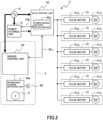
- an air conditioner 1 of the present embodiment has a multi-type configuration, and for example, one outdoor unit 2 is connected to three indoor units, which are an indoor unit 3A, an indoor unit 3B, and an indoor unit 3C, by first piping 6 and second piping 7 as refrigerant piping through which a refrigerant flows.
- An inside of a refrigeration cycle, which is connected by the first piping 6 and the second piping 7, is filled with a flammable refrigerant, for example, a slightly flammable refrigerant HFC-R32.
- the air conditioner 1 includes a shutoff unit 4 which is capable of shutting off a flow of the refrigerant between the outdoor unit 2 and the indoor units 3 and a power storage unit 5.
- a lithium-ion battery which is chargeable and dischargeable is desirably used, but this is not restrictive, and a large-capacity capacitor may be used.
- the indoor unit will simply be referred to as the indoor unit 3 without adding A, B, or C.
- power supply paths from an external power source 8 to the outdoor unit 2, the indoor units 3, and the shutoff unit 4 are schematically illustrated by relatively bold solid lines, and a power supply path from the power storage unit 5 to the shutoff unit 4 is schematically illustrated by a relatively bold broken line.
- the outdoor unit 2 and the indoor units 3 are connected together by the first piping 6 corresponding to refrigerant piping through which a liquid refrigerant mainly flows and the second piping 7 corresponding to gas refrigerant piping through which a gaseous refrigerant mainly flows.
- Those pieces of first piping 6 and second piping 7 correspond to a refrigerant piping system which connects the outdoor unit 2 and the indoor units 3 together.
- the outdoor unit 2 includes an outdoor heat exchanger 21, an outdoor expansion valve 22, an outdoor air blower 23, a four-way valve 24, a compressor 25, and so forth.
- a configuration of the outdoor unit 2 which is illustrated in Figure 1 is one example, and a configuration is possible which includes an accumulator, a pressure sensor, and so forth, for example.
- it is sufficient that the number of indoor units 3 is one or more, and a plurality of outdoor units 2 may further be connected in parallel in the refrigeration cycle.
- the indoor unit 3 includes an indoor control unit 30, an indoor heat exchanger 31, an indoor expansion valve 32 which is provided on the first piping 6 side of the indoor heat exchanger 31, an indoor air blower 33, and so forth.
- the indoor control unit 30 is configured with a microcomputer which is not illustrated and controls actions of the indoor unit 3 such as start and stop of an operation and actions of the indoor expansion valve 32 and the indoor air blower 33, the actions accompanying the actions of the indoor unit 3.
- the indoor control unit 30 is connected to a manipulation panel, a so-called remote manipulation device, by which a starting manipulation or a stopping manipulation of an operation is input and a temperature of an air-conditioning target space 100 is set and displayed and which is not illustrated, and controls the air conditioner 1 in accordance with an instruction by the manipulation panel.
- the indoor control unit 30 is connected to a refrigerant leakage detection unit 30a.
- the refrigerant leakage detection unit 30a includes a gas sensor 9 which detects a flammable refrigerant in air, and when a signal indicating that the refrigerant is detected is input from the gas sensor 9, the refrigerant leakage detection unit 30a determines that a refrigerant leakage is occurring in the vicinity of the indoor unit 3.
- a buzzer 60 as a sound output unit is connected to the refrigerant leakage detection unit 30a, and as described later, the refrigerant leakage detection unit 30a causes the buzzer 60 to sound in a case where the refrigerant leakage is detected.
- the buzzer 60 can be provided in the indoor control unit 30.
- the gas sensor 9 is provided in the indoor unit 3, but the gas sensor 9 can be installed in the air-conditioning target space 100 in such a manner that the gas sensor 9 is installed in a lower position in the air-conditioning target space 100, for example, in order to detect a refrigerant which is in general heavier than the air.
- the indoor control unit 30 and the refrigerant leakage detection unit 30a may be connected together by a signal cable or the like.
- the three indoor units 3A, 3B, and 3C are in parallel connected to the single refrigerant piping system. Further, in the present embodiment, it is assumed that the three indoor units 3A to 3C respectively perform air conditioning for air-conditioning target spaces 100a to 100c.
- the refrigeration cycle for air conditioning for the air-conditioning target spaces 100 is constructed with those outdoor unit 2, indoor units 3, and refrigeration piping system.
- a configuration of the refrigeration cycle which is illustrated in Figure 1 the number of indoor units 3 to be connected to the refrigeration piping system, the number of air-conditioning target spaces 100, the number of indoor units 3 to be installed in the air-conditioning target space 100, and so forth are examples, and those are not restrictive.
- a configuration is possible in which a plurality of indoor units 3 perform air conditioning for one air-conditioning target space 100.
- the air conditioner 1 switches the four-way valve 24 such that as indicated by a solid-line arrow C, the refrigerant discharged from the compressor 25 is supplied to the indoor units 3 via the outdoor heat exchanger 21, the outdoor expansion valve 22, and the first piping 6 and such that the refrigerant flowing out from the indoor units 3 returns to the compressor 25 via the second piping 7.
- the air conditioner 1 switches the four-way valve 24 such that as indicated by a broken-line arrow H, the refrigerant discharged from the compressor 25 is supplied to the indoor units 3 via the second piping 7 and such that the refrigerant flowing out from the indoor units 3 returns to the outdoor heat exchanger 21 via the indoor expansion valves 32, the first piping 6, and the outdoor expansion valve 22.
- switching of the four-way valve 24 and an operation of the compressor 25 are controlled by an outdoor-side control device which controls the refrigeration cycle in accordance with an instruction from each of the indoor control units 30 and which is not illustrated.
- the shutoff unit 4 is configured with a plurality of shutoff valves 41 which are capable of shutting off the flow of the refrigerant between the outdoor unit 2 and the indoor units 3 and a valve control unit 42 which controls actions of the above shutoff valves 41.
- the shutoff valve 41 is a so-called motor-operated valve which is driven by a motor and is capable of adjusting an opening. Such a motor-operated valve driven by the motor is also referred to as a PMV (pulse motor valve).
- the shutoff valves 41 are respectively provided on the first piping 6 side and the second piping 7 side of each of the indoor units 3. Specifically, on the first piping 6 side of the indoor unit 3A, a shutoff valve 41A1 is provided between an indoor expansion valve 32A and the outdoor expansion valve 22, and on the second piping 7 side, a shutoff valve 41A2 is provided between an indoor heat exchanger 31A and the four-way valve 24.
- a shutoff valve 41B1 is provided between an indoor expansion valve 32B and the outdoor expansion valve 22, and on the second piping 7 side, a shutoff valve 41B2 is provided between an indoor heat exchanger 31B and the four-way valve 24.
- a shutoff valve 41C1 is provided between an indoor expansion valve 32C and the outdoor expansion valve 22, and on the second piping 7 side, a shutoff valve 41C2 is provided between an indoor heat exchanger 31C and the four-way valve 24.
- the air conditioner 1 causes those shutoff valves 41 to perform blocking actions and thereby becomes capable of shutting off the flow of the refrigerant between the first piping 6 and the indoor units 3 and between the second piping 7 and the indoor units 3. Accordingly, the concerned indoor unit 3 can be separated from the refrigeration cycle.
- the shutoff valve will simply be referred to as the shutoff valve 41 without adding A1 or the like.
- the actions of those shutoff valves 41 are controlled by the valve control unit 42.
- the valve control unit 42 is configured with a microcomputer or the like which is not illustrated and executes processes for controlling the actions of the shutoff valves 41.
- the valve control unit 42 controls the actions of each of the shutoff valves 41 provided in each of the indoor units 3.
- a configuration is made such that the shared shutoff unit 4 is provided for the plurality of indoor units 3 which are in parallel connected to the single refrigerant piping system and as illustrated in Figure 2 , the shared valve control unit 42 performs centralized control of the actions of the shutoff valves 41 which are correspondingly provided in the indoor units 3.
- valve control unit 42 may be provided for each of the indoor units 3, and it is also possible to install, in a combined manner, the valve control unit 42 which performs centralized control for a few indoor units 3 and the valve control unit 42 which individually controls each of the indoor units 3.
- a portion except the external power source 8 and the indoor unit 3 in Figure 2 corresponds to the shutoff unit 4.
- the valve control unit 42 is connected to the indoor control unit 30 by a communication line 42c and is capable of mutual exchange of signals. From the indoor control unit 30 to the valve control unit 42, a signal about refrigerant leakage detection and an opening instruction about the blocked shutoff valve 41, which will be described later, are given.
- the valve control unit 42 includes a power source shutoff detection unit 42a which detects shutoff of supply of power from the external power source 8.
- the power source shutoff detection unit 42a is realized by combining a voltage detector of the external power source 8 and software which is provided by execution of a program by the valve control unit 42.
- a configuration is possible in which the whole power source shutoff detection unit 42a is realized with hardware.
- the power source shutoff detection unit 42a monitors the supply of power from the external power source 8 and determines that a state where the supply of power from the external power source 8 is shut off is established when power from the external power source 8 is not supplied. In the following, such a state will be referred to as power source shutoff. Note that the power source shutoff is assumed to occur due to a power outage, damage to a power supply path, incorrect shutoff by a circuit breaker, or the like, for example.
- the power storage unit 5 is connected to the valve control unit 42 by a signal line 42b and supplies power to the shutoff unit 4 when the external power source 8 is shut off due to a power outage or the like.
- the power storage unit 5 is constantly charged by power supplied from the external power source 8 while the power is supplied from the external power source 8 and stores power, and the power storage unit 5 supplies the stored power to the valve control unit 42 and the shutoff valves 41 of the shutoff unit 4 based on a start instruction from the valve control unit 42 which is output via the signal line 42b when the power source shutoff is detected.
- the shutoff unit 4 is configured such that the valve control unit 42 and the shutoff valves 41 are capable of actions even in a case where the power source shutoff occurs.
- valve control unit 42 in order to cause the valve control unit 42 to be capable of actions in a period until the supply of power from the power storage unit 5 is started after the external power source 8 is shutoff, for example, an auxiliary power source circuit such as a large-capacity capacitor, which is not illustrated, can be provided.
- an auxiliary power source circuit such as a large-capacity capacitor, which is not illustrated, can be provided.
- a configuration which constantly supplies power from the power storage unit 5 to the valve control unit 42 a configuration is possible which switches the supply of power from the external power source 8 to the shutoff valves 41 to the supply of power from the power storage unit 5 side in a case where the external power source 8 is shutoff.
- the shutoff valve 41 is different from a so-called electromagnetic valve of a solenoid type and is a motor-operated valve which controls opening and closing by rotation of a motor and which is also referred to as a pulse motor valve.
- an action speed of the shutoff valve 41 for closing a flow path is slow compared to a common electromagnetic valve.
- the action speed mentioned here means a time required until an opened flow path is closed or a time required until the closed flow path is opened. For example, this means that the action speed becomes faster as the time required until the flow path is closed becomes shorter and the action speed becomes slower as the time required until the flow path is closed becomes longer.
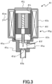
- the shutoff valve 41 includes a valve main body 41c which has a first connection end 41a serving as an entrance or an exit of the refrigerant and a second connection end 41b serving as an exit or an entrance of the refrigerant. Note that in a case where the first connection end 41a serves as the entrance of the refrigerant, the second connection end 41b serves as the exit of the refrigerant, and in a case where the first connection end 41a serves as the exit of the refrigerant, the second connection end 41b serves as the entrance of the refrigerant.
- valve seat 41d is formed which is formed to be hollow and is a cylindrical opening connected to the second connection end 41b. Further, the valve main body 41c houses a valve rod 41e which is arranged in a position coaxial with the valve seat 41d and which is relatively movable to the valve main body 41c in an up-down direction in Figure 3 .
- a surface on a distal end side of the valve rod 41e, which is positioned on a lower side in Figure 3 is formed as a male screw, the valve rod 41e is fixed to the valve main body 41c and is caused to pass through a bearing portion 41f, and a part of the bearing portion 41f through which the valve rod 41e passes through is formed as a female screw.
- valve rod 41e in Figure 3 is fixed to a rotor 41h of a pulse motor 41g.
- the rotor 41h is a rotor which has a plurality of magnetic poles and is provided to be integrally and coaxially rotatable with the valve rod 41e and to be slidable in the up-down direction in Figure 3 relatively to a casing body 41i.
- FIG. 3 An upper end side of the casing body 41i in Figure 3 is closed by a lid member 41j. Further, the casing body 41i is positioned in an outer periphery in a range in which the rotor 41h is slidable, and a stator 41k of the pulse motor 41g is provided on the casing body 41i.
- the stator 41k is formed with a coil 411 as is well known, and a lead wire 41m which is connected to the valve control unit 42 side as illustrated in Figure 2 is led out from the coil 411.
- a predetermined energization pulse is output to the pulse motor 41g when a control signal is input from the valve control unit 42 side, the rotor 41h having the magnetic poles thereby rotates together with the valve rod 41e, and because a male screw portion in an intermediate portion of the valve rod 41e is inserted in a female screw portion of the bearing portion 41f, the valve rod 41e moves in the up-down direction in Figure 3 in accordance with the rotation.
- Figure 2 does not illustrate a driving circuit which is for driving the pulse motor 41g and is configured with a transistor bridge or the like, for example.
- valve rod 41e is arranged in a position coaxial with the valve seat 41d, and a distal end of the valve rod 41e, which is positioned on the lower side in Figure 3 , is formed into a wedge shape, for example, which is capable of being inserted in and pulled out from the valve seat 41d. Further, when the distal end of the valve rod 41e is put into the valve seat 41d and the valve seat 41d is clogged by the valve rod 41e, the flow path of the refrigerant between the first connection end 41a and the second connection end 41b is blocked. This state corresponds to a state where the shutoff valve 41 is closed. In the following, a position of the valve rod 41e in the state where the shutoff valve 41 is closed will be referred to as a stoppage position.
- the flow path of the refrigerant between the first connection end 41a and the second connection end 41b is at least partially opened.
- This state corresponds to a state where the shutoff valve 41 is opened.
- a flow amount of the refrigerant can be adjusted by changing the position of the valve rod 41e.
- valve rod 41e when the valve rod 41e is slightly lifted upward in Figure 3 from the stoppage position, the flow path of the refrigerant is a little formed in a portion of the valve seat 41d. This flow path becomes larger as the valve rod 41e is further lifted upward in Figure 3 and becomes a maximum when the valve rod 41e is completely pulled out from the valve seat 41d.
- the opening of the shutoff valve 41 can be adjusted by the position of the valve 41e. In the following, the position of the valve rod 41e which is lifted to an upper limit on the upper side in Figure 3 will be referred to as an open position.
- the air conditioner 1 includes the shutoff valves 41 which are capable of shutting off the flow of the refrigerant in the refrigerant piping system.
- the shutoff valves 41 which are capable of shutting off the flow of the refrigerant in the refrigerant piping system.
- the air conditioner 1 has to shut off the flow of the refrigerant by causing the shutoff valves 41 to act.
- the power storage unit 5 is provided in the air conditioner 1, and it thereby becomes possible to shut off the flow of the refrigerant by causing the valve control unit 42 and the shutoff valves 41 to act for a certain time in a case where the external power source 8 is shutoff.
- shutoff valve 41 In a case where the shutoff valve 41 is blocked, there is a possibility that when the action speed of the shutoff valve 41 is slow, the refrigerant cannot quickly be shut off. Accordingly, it is desirable that the shutoff valve 41 be caused to act at as high speed as possible.
- the shutoff valve 41 which is driven to open or close by using a motor, driving the motor at a high speed results in large power consumption.
- the supply of power from the external power source 8 is shut off and the shutoff valves 41 are caused to act by using power from the power storage unit 5
- charged power of the power storage unit 5 is rapidly decreased by power consumption in driving the motors.
- valve-closing actions of the shutoff valves 41 are repeatedly performed in a short time, a charge amount of the power storage unit 5 is decreased, and the shutoff valves cannot be caused to act.
- shutoff valves 41 driven by the motors are caused to act at high speeds, driving torques of the motors become small, and the shutoff valves 41 cannot be caused to accurately act and cannot completely be closed.
- a pulse output speed of a pulse signal output from the valve control unit 42 is fast, there is a possibility that even when signals of the necessary number of pulses are output from the valve control unit 42, so-called pulse omission occurs because the rotations of the rotor 41h cannot respond to the number of pulses, and the shutoff valve 41 does not act to the stoppage position.
- the valve control unit 42 executes a process illustrated in a flowchart in Figure 4 and is thereby enabled to quickly and certainly shut off the refrigerant in accordance with a circumstance.
- the air conditioner 1 reduces the possibility that the shutoff valve 41 cannot be caused to act and is enabled to quickly shut off the refrigerant.
- the process by the valve control unit 42 which is illustrated in Figure 4 includes detection of the power source shutoff by the power source shutoff detection unit 42a.
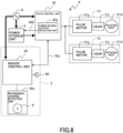
- processes by the indoor control unit 30 and the refrigerant leakage detection unit 30a, which cooperate with the valve control unit 42 are illustrated in Figure 5 .
- the valve control unit 42 determines whether or not a refrigerant leakage signal is received (S1), and in a case where the valve control unit 42 determines that the refrigerant leakage signal is not received (NO in S1), the valve control unit 42 determines whether or not the power source shutoff is detected (S7).
- reception of the refrigerant leakage signal means that the refrigerant leakage detection unit 30a detects a leakage of the refrigerant into a room and outputs a refrigerant leakage detection signal to the indoor control unit 30, the indoor control unit 30 transmits the refrigerant leakage signal indicating that a refrigerant leakage is detected to the valve control unit 42 via the communication line 42c, and the valve control unit 42 receives the above refrigerant leakage signal.
- the detection of the refrigerant leakage is performed by the refrigerant leakage detection unit 30a, and the refrigerant leakage detection unit 30a determines whether or not a concentration of refrigerant gas exceeds a predetermined value, that is, the refrigerant gas is detected (S11).
- the refrigerant gas is a gas refrigerant which is enclosed in the refrigeration cycle and which has leaked from the indoor unit 3 or piping in the vicinity of that.
- the refrigerant leakage detection unit 30a progresses to step S11 and continues the detection of the refrigerant gas.
- the refrigerant leakage detection unit 30a transmits the refrigerant leakage detection signal to the indoor control unit 30 (S12) and outputs a warning sound by causing the buzzer 60 to sound (S13).
- the refrigerant leakage detection unit 30a performs a process for transmitting the refrigerant leakage detection signal before a process for causing the buzzer 60 to sound. Note that instead of the buzzer 60 which outputs a predetermined sound by being energized, a configuration is possible which uses a speaker outputting a voice corresponding to an input signal.
- the sound output unit is a unit capable of outputting a sound.
- a light emitting element such as an LED may be provided and may be caused to emit light in response to the buzzer 60.
- the refrigerant leakage detection unit 30a determines whether a reset manipulation is performed or a reset signal is received (S14).
- the above reset manipulation or reset signal is input or transmitted by a manipulation by a maintenance-inspection worker after a measure against the refrigerant leakage is taken and the refrigerant leakage is solved.
- the refrigerant leakage detection unit 30a waits for the reset manipulation or reception of the reset signal while repeating the above step S14 and keeping the buzzer 60 sounding.
- the refrigerant leakage detection unit 30a stops sounding of the buzzer 60 (S15), performs a return, returns to an initial state, and again determines whether the refrigerant leakage signal is received.
- the refrigerant leakage detection unit 30a one time transmits the refrigerant leakage detection signal to the indoor control unit 30 and keeps the buzzer 60 sounding until the measure against the refrigerant leakage is taken and the refrigerant leakage is solved, in other words, until safety is confirmed.
- the indoor control unit 30 determines whether or not the refrigerant leakage detection signal from the refrigerant leakage detection unit 30a is received (S21), and in a case where the refrigerant leakage detection signal is not received (NO in S21), the indoor control unit 30 executes an ordinary operation process (S25), progresses to step S21, and keeps monitoring reception of the refrigerant leakage detection signal.
- the ordinary operation process denotes display of the temperature in the air-conditioning target space 100, acceptance of a manipulation such as a change in settings, a communication process with the outdoor unit 2, or the like.
- the indoor control unit 30 receives the refrigerant leakage detection signal (YES in S21), the indoor control unit 30 transmits the refrigerant leakage signal to the shutoff unit 4 (S22).
- the above refrigerant leakage signal is a signal for notifying that the refrigerant leakage is detected to the shutoff unit 4.
- the indoor control unit 30 determines whether an opening instruction input is performed (S23).
- the above opening instruction input is given by a manipulation by a user or by a higher-order control device, for example, after a measure against the refrigerant leakage is taken by the maintenance-inspection worker, the refrigerant leakage is solved, and safety is confirmed.
- the indoor control unit 30 waits.
- the indoor control unit 30 transmits the opening instruction to the shutoff unit 4 (S24) and performs a return.
- the indoor control unit 30 and the refrigerant leakage detection unit 30a perform the detection about the refrigerant, and a result of the detection is notified to the shutoff unit 4.
- the shutoff unit 4 performs control for blocking the shutoff valves 41. Specifically, as illustrated in Figure 4 , in a case where the valve control unit 42 of the shutoff unit 4 determines that the power source shutoff is not detected (NO in S7), the valve control unit 42 determines whether or not the shutoff valves 41 have been closed (S4). Further, in a case where the valve control unit 42 determines that the shutoff valves 41 have been closed (YES in S4), the valve control unit 42 determines whether the opening instruction for opening the shutoff valves 41 is given (S5).
- a case where YES is obtained in step S4 is a case where the refrigerant leakage is already detected or a power outage is already detected.
- the valve control unit 42 stores memory about a result of an immediately previous manipulation for either one of opening and closing for the shutoff valves 41 and makes an assessment by calling the memory.
- the opening instruction is performed by a notification from the indoor control unit 30 to the valve control unit 42 via the communication line 42c, similarly to refrigerant detection. Further, a condition that the opening instruction be transmitted from the indoor control unit 30 is different between a case where the refrigerant leakage is already detected and a case where the operation is restarted after the power source shutoff. That is, the opening instruction in a case where the refrigerant leakage is already detected is output only after the maintenance-inspection worker confirms a leakage part and repairs that part and a state is thereafter established where power is normally supplied from the external power source 8.
- an assessment that the maintenance-inspection worker already confirms the leakage part and already repairs the leakage part can preferably be approved under a condition that the reset manipulation or the reset signal be already accepted in the refrigerant leakage detection unit 30a (YES in S14).
- the opening instruction in a case where the refrigerant leakage is not detected and the shutoff valves 41 are closed only due to the power source shutoff is output when a state is established where power is normally supplied from the external power source 8 or when the user gives an instruction for a restart of operation by manipulating a remote manipulation device or the like after a state is established where power is normally supplied from the external power source 8. Consequently, in either case, closing to opening of the shutoff valves 41 is carried out in a state where power is normally supplied from the external power source 8. Thus, power of the power storage unit 5 is not used for valve-opening driving for the shutoff valves 41.
- the valve control unit 42 opens the shutoff valves 41 (S6).
- the valve control unit 42 outputs the pulse signals of X pulses to the pulse motor 41g at a predetermined pulse output speed (v4) and thereby opens the shutoff valve 41.
- the pulse output speed denotes a frequency of the pulse signal in driving the pulse motor 41g and corresponds to an opening-closing action speed of the shutoff valve 41.
- the opening-closing action speed of the shutoff valve 41 becomes faster as the pulse output speed becomes faster, and the action speed of the shutoff valve 41 becomes slower as the pulse output speed becomes slower.
- the pulse output speed (v4) is set slower than a pulse output speed (v1) in a case where the shutoff valve 41 is closed when the refrigerant leakage is detected.
- the pulse output speeds satisfy a relationship of v4 ⁇ v1.
- the number of pulses (X) to be output is the number of pulse signals which are necessary for causing the shutoff valve 41 to act from a stop position to the open position.
- X also denotes the number of pulse signals which are necessary for causing the shutoff valve 41 to act from the open position to the stop position.
- the valve control unit 42 opens the shutoff valves 41 and thereafter performs a return. Further, in a case where the valve control unit 42 determines that the shutoff valves 41 are already opened (YES in S4) and a case where the valve control unit 42 determines that the shutoff valves 41 are closed but the opening instruction is not given (NO in S5), the valve control unit 42 also performs a return. Note that it is described that a return is performed for easy understanding of a flow of the process, but the valve control unit 42 actually progresses to step S1 and repeatedly executes the above process during the action of the air conditioner 1.
- valve control unit 42 determines that the refrigerant leakage is detected (YES in S1), the valve control unit 42 outputs control signals of X pulses to the pulse motors 41g at the pulse output speed (v1) and thereby closes the shutoff valves 41 (S2). In this case, in the refrigerant leakage detection unit 30a, the buzzer 60 already sounds.
- the pulse output speed (v1) in the above case is set fastest among pulse output speeds in other processes for driving the shutoff valves 41.
- the valve control unit 42 sets the action speed of the shutoff valve 41 as fast as possible.
- the valve control unit 42 outputs the control signals of Y pulses to the pulse motor 41g at a pulse output speed (v2) and thereby certainly closes the shutoff valve 41 (S3).
- the pulse output speed (v2) is set smaller than the pulse output speed (v1).
- the number of pulses (Y) be the same number as the above-described number of pulses (X) or more, for example.
- valve control unit 42 performs the retightening by a whole displacement amount of the shutoff valve 41, which is caused to act from the open position to a closed position, and thereby performs certain blocking.
- a value of the number of pulses (Y) for the retightening which is described here, is one example and may appropriately be set in a range which is allowed by strength based on specifications of the shutoff valve 41.
- a process of the retightening has a technical significance as a measure against the above-described pulse omission in addition to a technical significance of certain closing of the shutoff valve 41 for prevention of the refrigerant leakage. That is, when the pulse omission occurs by any chance as a result of making faster the pulse output speed (v1) for causing the shutoff valve to quickly act, there is a possibility that the valve rod 41e stops while not reaching the stoppage position and cannot block the refrigerant piping and the refrigerant keeps leaking although its amount is small.
- the valve rod 41e can be moved to the stoppage position side by executing a process of the retightening in step S3.
- the control signals are output at the pulse output speed (v2) which is slower than the pulse output speed (v1), a tightening torque becomes large, the valve rod 41e can more strongly be rotated and pressed onto the valve seat 41d, and the shutoff valve 41 can thereby certainly be set to a closed state.
- step S4 the valve control unit 42 determines that the shutoff valves 41 are closed.
- the valve control unit 42 determines that the opening instruction is not given (NO in S5) and performs a return.
- the valve control unit 42 executes processes in order of YES in step S1, step S2, and step S3. Further, in a case where the valve control unit 42 determines that the refrigerant leakage is not detected (NO in S1) and a case where the valve control unit 42 determines that the power source shutoff is detected (YES in S7), the valve control unit 42 determines whether the shutoff valves 41 have been closed (S8). In a case where the valve control unit 42 determines that the shutoff valves 41 have been closed, that is, in a case where the refrigerant leakage is already detected or a power outage is already detected (YES in S8), the valve control unit 42 progresses to step S4. However, because the same determination is made in step S8 and step S4, the valve control unit 42 may progress to step S5 in a case of YES in step S8.
- the valve control unit 42 determines that the shutoff valves 41 are not closed in step S8, that is, in a case where refrigerant leakage detection is not previously made (NO in S8), the valve control unit 42 performs a closing action of the shutoff valves 41 in the power source shutoff.
- the control signals of X pulses are output to the pulse motor 41g at a pulse output speed (v3), and the shutoff valve 41 is thereby closed (S9).
- the pulse output speed (v3) is set slower than the pulse output speed (v1) in a case where the shutoff valve 41 is closed when the refrigerant leakage is detected.
- the pulse output speeds satisfy a relationship of v4 ⁇ v1, and in a case where the power source shutoff is detected, the valve control unit 42 sets the action speed of the shutoff valve 41 lower than that in a case where power is supplied from the external power source 8 and the refrigerant leakage is detected.
- the relationship among the pulse output speeds in the processes is v1 > v2, v1 > v3, and v1 > v4.
- the action speed becomes fastest, and the torque becomes smallest.
- the valve control unit 42 performs control such that the action speed of the shutoff valve 41 in a case where power is supplied from the external power source 8 and where the refrigerant leakage is detected becomes fastest. Note that in a normal state where neither the refrigerant leakage nor the power source shutoff is occurring, the valve control unit 42 repeats NO in step S1, NO in S7, and NO in S4, and the open state of the shutoff valves 41 is maintained.
- the shutoff valves 41 quickly shut off the refrigerant leakage, and the refrigerant leakage is certainly shut off by performing the retightening.
- control is performed such that the action speeds of the shutoff valves 41 become different between a case where power is supplied from the external power source 8 and a case where power from the power storage unit 5 is supplied. Further, as for the air conditioner 1, in the shutoff unit 4, control is performed such that the action speeds of the shutoff valves 41 become different between a case where the refrigerant leakage is detected and a case where the power source shutoff is detected. Further, as for the air conditioner 1, in the shutoff unit 4, control is performed such that the action speeds of the shutoff valves 41 become different between a case where the refrigerant leakage is detected when power is supplied from the external power source 8 and a case where the power source shutoff is detected. By those pieces of control, control of the shutoff valves 41 which corresponds to the supplied power becomes possible.
- the air conditioner 1 includes the outdoor unit 2, the indoor units 3 which are connected to the outdoor unit 2 by the refrigerant piping, the shutoff unit 4 which is capable of shutting off the flow of the refrigerant in the refrigerant piping between the outdoor unit 2 and the indoor units 3, and the refrigerant leakage detection units 30a which detect the refrigerant leakage.
- the shutoff unit 4 includes the shutoff valves 41 which shut off the flow of the refrigerant in the refrigerant piping and the valve control unit 42 which controls the actions of the shutoff valves.
- the shutoff valve 41 is the motor-operated valve which is driven by the motor, and in a case where the refrigerant leakage is detected by the refrigerant leakage detection unit 30a, the valve control unit 42 performs control so as to block the shutoff valves at the action speed (v1) and subsequently performs control so as to retighten the shutoff valves at the action speed (v2) which is slower than the action speed (v1).
- the valve-closing action is performed for the shutoff valves 41 at the relatively fast action speed (v1), and the refrigerant stream to the indoor units 3 can thereby quickly be shut off.
- the retightening is performed at the relatively slow action speed (v2), the pulse omission thereby does not occur, and the shutoff valves 41 can certainly be closed.
- shutoff valves 41 can quickly and certainly be closed as described above, in a case where the refrigerant is a flammable refrigerant, danger that the leaking refrigerant catches fire can be reduced, and the configuration is thus very significant for securing safety.
- the air conditioner 1 includes the buzzer 60, and in a case where the refrigerant leakage is detected by the refrigerant leakage detection unit 30a, the valve control unit 42 causes the buzzer 60 to sound. Accordingly, in a case where the refrigerant leaks and even a slight danger is assumed to be present, that fact can quickly be informed.
- a valve body like a rotating body 51d collides with a stopper like an abutting portion 51f, for example, due to a backlash in a speed reduction mechanism at each occurrence of the pulse energization, and a collision sound might thereby repeatedly be produced.
- the buzzer 60 is caused to sound before the retightening is performed, the collision sound can thereby be masked by the sound of the buzzer 60, and the user can be prevented from being annoyed. Further, there is a possibility that the user might feel uneasiness when the buzzer 60 sounds and then a sound of closing of the shutoff valve 41 is produced, but such a possibility can be reduced by causing the buzzer 60 to sound. Further, the user can be inhibited from having incorrect recognition that the air conditioner 1 has trouble when some sounds are made.
- valve control unit 42 performs control such that the action speed (v1) of the shutoff valve 41 in a case where the refrigerant leakage is detected by the refrigerant leakage detection unit 30a becomes faster than the action speed (v4) at a time when the shutoff valve 41 is opened. Accordingly, the refrigerant stream to the indoor unit 3 can quickly be shut off.
- the valve control unit 42 makes the action speed (v2) at a time when the shutoff valve 41 is retightened in a case where the refrigerant leakage is detected by the refrigerant leakage detection unit 30a become equivalent to the action speed (v4) at a time when the shutoff valve 41 is opened. Accordingly, an opening action of the shutoff valve 41 can be performed by torque equivalent to that in the retightening, and the shutoff valve 41 can certainly be opened.
- making the action speeds equivalent which is mentioned here, includes a state where the action speed (v2) in the retightening falls within an allowable range of approximately 10% of the action speed (v4) at a time when the shutoff valve 41 is opened.
- the valve control unit 42 makes the number of pulses (Y), which are output when the shutoff valve 41 is retightened in a case where the refrigerant leakage is detected by the refrigerant leakage detection unit 30a, become equivalent to the number of pulses (X) at a time when the valve-closing action of the shutoff valve 41 is performed from a fully open condition to a fully closed condition. Accordingly, the retightening is further performed after the valve-closing action, and the refrigerant stream to the indoor unit 3 can certainly be shut off.
- the air conditioner 1 includes the shutoff unit 4 which is capable of shutting off the flow of the refrigerant in the refrigerant piping connecting the outdoor unit 2 and the indoor units 3 together, the power storage unit 5 which is capable of supplying power to the shutoff unit 4 in a case where power from the external power source 8 is shut off, the refrigerant leakage detection unit 30a which detects the refrigerant leakage, and the power source shutoff detection unit 42a which detects that the supply of power from the external power source 8 is shut off.
- the shutoff unit 4 includes the shutoff valves 41 which are driven by the motors and shut off the flow of the refrigerant in the refrigerant piping and the valve control unit 42 which controls the actions of the shutoff valves 41.
- the valve control unit 42 blocks the shutoff valves 41 and makes the action speed of the shutoff valve 41 in a case where the refrigerant leakage is detected become faster than the action speed of the shutoff valve 41 in a case where it is detected that the supply of power from the external power source 8 is shut off.
- the air conditioner 1 makes the action speed in a period until the shutoff valve 41 is closed in a case where the refrigerant leakage is detected become slower than the action speed in a period until the shutoff valve 41 is closed in a case where the power is supplied from the power storage unit 5. Accordingly, the flow of the refrigerant can quickly be shut off in the refrigerant leakage, a further leakage of a flammable refrigerant can be inhibited, and safety can be improved.
- the action speed be made fast in the power source shutoff, but in order to avoid, as much as possible, a worst situation where the shutoff valves cannot be manipulated due to a power shortage of the power storage unit 5 at a critical moment when the valve-closing action is necessary, the action speed in the period until the shutoff valve 41 is closed in a case where power is supplied from the power storage unit 5 is made slow.
- the plurality of indoor units 3 are provided in parallel in the single refrigerant piping system
- the shutoff unit 4 is provided for the plurality of indoor units 3 in a shared manner
- the valve control unit 42 controls the actions of the plurality of shutoff valves 41 which are provided in each of the plurality of indoor units 3. Accordingly, control about the plurality of indoor units 3 can collectively be performed, and a possibility that a configuration becomes complicated can be reduced.
- air conditioner 1 can appropriately be changed without departing from the spirit and scope thereof.
- the air conditioner 1 in a case where the air conditioner 1 includes a plurality of indoor units 3 in a single refrigerant piping system and where each of the indoor units 3 is installed in the different air-conditioning target space 100, the air conditioner 1 can have a configuration in which the shutoff unit 4 is provided for each of the indoor units 3. That is, in a case where the plurality of indoor units 3 are provided in parallel in the single refrigerant piping system, a configuration is possible in which a plurality of shutoff units 4 are individually provided for the plurality of indoor units 3 and the valve control unit 42 of each of the shutoff units 4 controls actions of the shutoff valves 41 which are provided for the corresponding indoor unit 3.
- shutoff valves 41 In a case of such a configuration, a possibility can be reduced that the shutoff valves 41 cannot be caused to act due to a power shortage, the refrigerant can also quickly be shut off, and further the retightening for more certainly shutting off the refrigerant leakage can be performed, for example. It becomes possible to cause the shutoff valves 41 to certainly act, and similar effects to those of the embodiment can be obtained such as an effect in which the refrigerant can quickly and certainly be shut off in accordance with a circumstance.
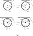
- the shutoff valve 41 of a type in which the valve rod 41e is linearly moved is raised as an example, but as the shutoff valve 41, for example, an electric rotary valve 51 can be used, which is illustrated in Figure 7 and is also referred to as a ball valve.
- the electric rotary valve 51 has a housing portion 51c which is formed with a first opening 51a serving as an entrance or an exit of the refrigerant and a second opening 51b serving as an exit or an entrance of the refrigerant and the rotating body 51d which is arranged in the housing portion 51c.
- the rotating body 51d is formed into a spherical shape, and in its internal portion, an internal flow path 51e is formed which is capable of connecting the first opening 51a and the second opening 51b together.
- the rotating body 51d may be formed into a columnar shape which is rotatable around a rotation axis (J1) as a center.
- a position of the internal flow path 51e is changed by rotating the rotating body 51d around the rotation axis (J1), and switching can thereby be performed between a state where the first opening 51a and the second opening 51b are connected together by the internal flow path 51e and the shutoff valve 41 is thereby opened, which is illustrated as a flow-path open state, and a state where the first opening 51a and the second opening 51b are not connected together and the shutoff valve 41 is thereby closed, which is illustrated as a flow-path closed state.
- the abutting portion 51f protruding from an inner wall to an inner periphery side is formed in the housing portion 51c, and a groove portion 51g recessed to the inner periphery side is formed in the rotating body 51d.
- the rotating body 51d is rotated around the rotation axis (J1), one end portion 51h of the groove portion 51g thereby contacts with the abutting portion 51f, and a state is established where rotation is stopped, the first opening 51a and the second opening 51b are connected together by the internal flow path 51e, and a state is established where the shutoff valve 41 is opened.
- a gear 51j as a speed reducer is arranged on an output shaft of the pulse motor 41g, and a ball as the rotating body 51d is driven via the gear 51j. Accordingly, torque for causing the rotating body 51d to rotate while sliding on the inner wall of the housing portion 51c can be exerted.
- the refrigerant leakage detection unit 30a determines whether the refrigerant gas is detected (S11), and in a case where the refrigerant gas is not detected (NO in S11), the refrigerant leakage detection unit 30a performs a return, in other words, progresses to step S11 and continues the detection of the refrigerant gas. On the other hand, in a case where the refrigerant gas is detected (YES in S11), the refrigerant leakage detection unit 30a transmits the refrigerant leakage detection signal to the indoor control unit 30 (S12).
- the refrigerant leakage detection unit 30a determines whether the reset manipulation is performed or whether the reset signal is received (S14), and in a case where the reset manipulation is not performed or the reset signal is not received either (NO in S14), the refrigerant leakage detection unit 30a waits. On the other hand, in a case where a measure against the refrigerant leakage is completed and the reset manipulation is performed or a case where the reset signal is received (YES in S14), the refrigerant leakage detection unit 30a stops sounding of the buzzer 60 (S15) and performs a return.
- the indoor control unit 30 determines whether or not the refrigerant leakage detection signal from the refrigerant leakage detection unit 30a is received (S21), and in a case where the refrigerant leakage detection signal is not received (NO in S21), the indoor control unit 30 executes the ordinary operation process (S25), performs a return, in other words, progresses to step S21, and keeps monitoring reception of the refrigerant leakage detection signal.
- the indoor control unit 30 transmits the refrigerant leakage signal to the shutoff unit 4 (S22) and causes the buzzer 60 to sound (S31).
- the indoor control unit 30 determines whether the opening instruction input is given (S23), and in a case where the opening instruction input is not given (NO in S23), the indoor control unit 30 waits. On the other hand, in a case where the opening instruction input is given (YES in S23), the indoor control unit 30 transmits the opening instruction to the shutoff unit 4 (S24), stops sounding of the buzzer 60, and performs a return.
- the buzzer 60 is caused to sound before the retightening is performed, the collision sound can thereby be masked by the sound of the buzzer 60, and the user can be prevented from being annoyed. Further, the user can be inhibited from having incorrect recognition that the air conditioner 1 has trouble when some sounds are made.
- the buzzer may be provided in the valve control unit 42, and the buzzers may be provided in a plurality of parts.
- a configuration in which the dedicated valve control unit 42 is provided in the shutoff unit 4 is raised as an example, but a configuration is possible in which the indoor control unit 30 concurrently serves as the valve control unit 42, and a configuration is possible in which a control unit of a manipulation panel concurrently serves as the valve control unit 42, the control unit of the manipulation panel accepting inputs of a starting manipulation and a stopping manipulation of an operation of each of the indoor units 3 and displaying the temperature of the air-conditioning target space 100.
- the control unit of the manipulation panel can concurrently serve as the indoor control unit 30.
- the gas sensor 9 is not limited to a sensor which detects the refrigerant and can have a configuration in which the leakage is detected based on a pressure change or a flow amount change of the refrigerant or a combination of those.
Landscapes
- Engineering & Computer Science (AREA)
- Physics & Mathematics (AREA)
- Mechanical Engineering (AREA)
- Thermal Sciences (AREA)
- General Engineering & Computer Science (AREA)
- Air Conditioning Control Device (AREA)
Applications Claiming Priority (1)
| Application Number | Priority Date | Filing Date | Title |
|---|---|---|---|
| PCT/JP2021/047635 WO2023119506A1 (ja) | 2021-12-22 | 2021-12-22 | 空気調和機 |
Publications (2)
| Publication Number | Publication Date |
|---|---|
| EP4455580A1 true EP4455580A1 (de) | 2024-10-30 |
| EP4455580A4 EP4455580A4 (de) | 2025-09-24 |
Family
ID=86901642
Family Applications (1)
| Application Number | Title | Priority Date | Filing Date |
|---|---|---|---|
| EP21968943.7A Pending EP4455580A4 (de) | 2021-12-22 | 2021-12-22 | Klimaanlage |
Country Status (3)
| Country | Link |
|---|---|
| EP (1) | EP4455580A4 (de) |
| JP (1) | JP7663717B2 (de) |
| WO (1) | WO2023119506A1 (de) |
Family Cites Families (6)
| Publication number | Priority date | Publication date | Assignee | Title |
|---|---|---|---|---|
| JPS63178985A (ja) * | 1987-01-19 | 1988-07-23 | カネボウ株式会社 | クラツチ圧力制御装置 |
| JPH06328330A (ja) * | 1993-05-20 | 1994-11-29 | Kanzaki Kokyukoki Mfg Co Ltd | 締め付け装置 |
| JP6304330B2 (ja) * | 2016-09-02 | 2018-04-04 | ダイキン工業株式会社 | 冷凍装置 |
| JP7407374B2 (ja) | 2019-02-19 | 2024-01-04 | パナソニックIpマネジメント株式会社 | 空気調和装置 |
| JP7315845B2 (ja) * | 2019-11-29 | 2023-07-27 | ダイキン工業株式会社 | 空気調和装置 |
| US12235029B2 (en) * | 2020-03-30 | 2025-02-25 | Mitsubishi Electric Corporation | Air-conditioning system with separate refrigerant leak sensors |
-
2021
- 2021-12-22 WO PCT/JP2021/047635 patent/WO2023119506A1/ja not_active Ceased
- 2021-12-22 JP JP2023568895A patent/JP7663717B2/ja active Active
- 2021-12-22 EP EP21968943.7A patent/EP4455580A4/de active Pending
Also Published As
| Publication number | Publication date |
|---|---|
| JPWO2023119506A1 (de) | 2023-06-29 |
| WO2023119506A1 (ja) | 2023-06-29 |
| EP4455580A4 (de) | 2025-09-24 |
| JP7663717B2 (ja) | 2025-04-16 |
Similar Documents
| Publication | Publication Date | Title |
|---|---|---|
| JP7407374B2 (ja) | 空気調和装置 | |
| JP3703346B2 (ja) | 空気調和機 | |
| EP4357704A1 (de) | Absperrventilsteuerungsvorrichtung für kältekreislauf und klimaanlage | |
| EP1176346B1 (de) | Elektrisch angetriebenes Ventil zum Wählen einer von mehreren Durchflussöffnungen in einem Kältekreislauf | |
| JP2015094574A (ja) | 空気調和機 | |
| EP4567338A1 (de) | Kältekreislaufvorrichtung | |
| EP4455579A1 (de) | Klimaanlage | |
| EP4455580A1 (de) | Klimaanlage | |
| CN111121154B (zh) | 一种多联空调机 | |
| KR20130033847A (ko) | 공기 조화기의 제어 장치, 이를 포함한 공기 조화기 및 자가 진단 방법 | |
| JP6068121B2 (ja) | 空気調和機 | |
| US10047993B2 (en) | Engine driven heat pump | |
| JP2007155226A (ja) | 空気調和機 | |
| EP3382294A1 (de) | Klimatisierungssystem und darin verwendete innenraumeinheit | |
| KR102055162B1 (ko) | 공기 조화기 및 이의 제어 방법 | |
| CN111121155B (zh) | 一种多联空调机 | |
| EP4379274A1 (de) | Klimaanlage | |
| US9862252B2 (en) | Engine driven heat pump | |
| JP3343400B2 (ja) | 空気調和機の制御装置 | |
| JP3178348B2 (ja) | 空気調和装置の制御装置 | |
| JP4015665B2 (ja) | 空気調和機 | |
| JPH0444985Y2 (de) | ||
| WO2022190820A1 (ja) | 冷凍システム | |
| JP3178349B2 (ja) | 空気調和装置の制御装置 | |
| JPH08219523A (ja) | 空気調和装置 |
Legal Events
| Date | Code | Title | Description |
|---|---|---|---|
| STAA | Information on the status of an ep patent application or granted ep patent |
Free format text: STATUS: THE INTERNATIONAL PUBLICATION HAS BEEN MADE |
|
| PUAI | Public reference made under article 153(3) epc to a published international application that has entered the european phase |
Free format text: ORIGINAL CODE: 0009012 |
|
| STAA | Information on the status of an ep patent application or granted ep patent |
Free format text: STATUS: REQUEST FOR EXAMINATION WAS MADE |
|
| 17P | Request for examination filed |
Effective date: 20240624 |
|
| AK | Designated contracting states |
Kind code of ref document: A1 Designated state(s): AL AT BE BG CH CY CZ DE DK EE ES FI FR GB GR HR HU IE IS IT LI LT LU LV MC MK MT NL NO PL PT RO RS SE SI SK SM TR |
|
| DAV | Request for validation of the european patent (deleted) | ||
| DAX | Request for extension of the european patent (deleted) | ||
| A4 | Supplementary search report drawn up and despatched |
Effective date: 20250826 |
|
| RIC1 | Information provided on ipc code assigned before grant |
Ipc: F25B 49/02 20060101AFI20250820BHEP |