EP4455436B1 - Verankerungsvorrichtung für türen oder fenster - Google Patents
Verankerungsvorrichtung für türen oder fenster Download PDFInfo
- Publication number
- EP4455436B1 EP4455436B1 EP24171910.3A EP24171910A EP4455436B1 EP 4455436 B1 EP4455436 B1 EP 4455436B1 EP 24171910 A EP24171910 A EP 24171910A EP 4455436 B1 EP4455436 B1 EP 4455436B1
- Authority
- EP
- European Patent Office
- Prior art keywords
- anchoring device
- main body
- axis
- expansion means
- expandable
- Prior art date
- Legal status (The legal status is an assumption and is not a legal conclusion. Google has not performed a legal analysis and makes no representation as to the accuracy of the status listed.)
- Active
Links
Images


Classifications
-
- E—FIXED CONSTRUCTIONS
- E06—DOORS, WINDOWS, SHUTTERS, OR ROLLER BLINDS IN GENERAL; LADDERS
- E06B—FIXED OR MOVABLE CLOSURES FOR OPENINGS IN BUILDINGS, VEHICLES, FENCES OR LIKE ENCLOSURES IN GENERAL, e.g. DOORS, WINDOWS, BLINDS, GATES
- E06B3/00—Window sashes, door leaves, or like elements for closing wall or like openings; Layout of fixed or moving closures, e.g. windows in wall or like openings; Features of rigidly-mounted outer frames relating to the mounting of wing frames
- E06B3/30—Coverings, e.g. protecting against weather, for decorative purposes
- E06B3/301—Coverings, e.g. protecting against weather, for decorative purposes consisting of prefabricated profiled members or glass
- E06B3/302—Covering wooden frames with metal or plastic profiled members
Definitions
- the anchoring device for doors or windows is intended for use in the building and construction sector, in particular in the sector of doors or windows, for example doors or windows made by assembling members of different materials together (e.g., windows and/or French doors or windows in wood/aluminium, aluminium/wood and PVC).
- the present invention is precisely for doors or windows made of wood-aluminium which comprise a wooden frame and an aluminium covering which is arranged on the outer side of the wooden frame so as to protect it from the weather.
- a door or window is typically used to physically isolate an internal environment, such as a room in a house, from the external environment. That is, a door or window defines a barrier between the aforesaid internal environment and the external environment so as to prevent atmospheric agents (e.g., rain, hail, wind) from entering the internal environment.
- atmospheric agents e.g., rain, hail, wind
- the anchoring devices commonly used are known in the technical jargon of the field as clips.
- a further drawback lies in the fact that the anchoring devices of known type require tools for their assembly.
- the connection of such devices to the frame of a door or window is commonly carried out by means of threaded elements.
- Such elements are screwed using a screwing tool. This makes the devices of known type inconvenient to use and, in some environments, in particular in places where there is no electric power outlet nearby, such devices are unusable.
- DE19546346C5 discloses an anchoring device for doors or windows with the features of the preamble of claim 1.
- DE8815464U1 also discloses an anchoring device for doors or windows.
- the object of the present invention is to provide an anchoring device which allows to overcome, at least in part, the above-mentioned drawbacks of the prior art.
- a further object of the present invention is to provide an anchoring device which is easy and fast to use.
- a further object of the present invention is to provide an anchoring device which is structurally and functionally completely reliable.
- a further object of the present invention is to provide an anchoring device which is economically advantageous.
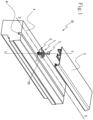
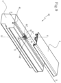
- the present invention relates to an anchoring device which, with reference to the appended figures, has been generally indicated by the number 1.
- the first member 3 is preferably a covering, cladding or similar element (e.g., a cornice made of aluminium or other material), and the second member 4 is preferably a frame (e.g., made of wood), preferably rectangular in shape, which preferably internally defines at least one seat, e.g., to accommodate a substantially plate-like element and preferably made of glass.
- a covering, cladding or similar element e.g., a cornice made of aluminium or other material
- the second member 4 is preferably a frame (e.g., made of wood), preferably rectangular in shape, which preferably internally defines at least one seat, e.g., to accommodate a substantially plate-like element and preferably made of glass.
- the shaped portion 21 of the main body 2 also preferably comprises a fixed portion 21" which defines a coupling shaping, relative to a section transverse to the axis X, so as to achieve a stable coupling with the first member 3.
- the first and second portions 22', 22" preferably have at least one protuberance, preferably protruding in projection, relative to the axis Y, to achieve a stable coupling of the main body 2 with the second member.
- a protuberance is defined by knurls or serrations on the external surface of such first and second portions 22', 22".
- connection between the expandable portion 22 and the second member 4 is stable and long-lasting.
- the housing volume 23 of the expandable portion 22 extends substantially along the axis Y and passes through the expandable portion 22 and through the shaped portion 21 of the main body 2.
- the housing seat 6 of the fixed portion 21" is arranged so that the axis Y passes substantially through the centreline of the seat 6 itself.
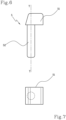
- the tail portion 52 has a transverse overall dimension relative to the axis Y which is greater relative to at least part of the housing volume 23.
- the head portion 51 further has, preferably, an enlarged portion according to a direction transverse to the axis Y, relative to the tail portion 52, to preferably define a mechanical abutment in the second position.
- the tail portion 52 penetrates the housing volume 23 of the expandable portion 22 by a predetermined amount and preferably equal to the length of the tail portion 52 itself.
- the main body 2 and the expansion means 5 are preferably made by means of a moulding process, such as injection moulding in particular.
- a moulding process such as injection moulding in particular.
- the main body 2 and the expansion means 5 are obtained in a simple manner, in particular in the case in which such a main body 2 and such expansion means 5 define complex shapes.
- a door or window 10 comprising a frame defining the second member 4 and a covering of at least part of the frame defining the first member 3.
- the anchoring device 1 is arranged between the first member 3 and the second member 4 to mechanically connect them together.
- the groove 41 has a shape of the transverse section along the axis Y which is substantially counter-shaped to the section of the expandable portion 22 along the axis Y.
- the groove 41 has a substantially rectangular shape of the transverse section along the axis Y.
- the groove 41 preferably defines a seat which acts as a mechanical abutment for positioning the main body 2 on the second member 4 (e.g., on the frame). Thereby, the main body 2 is mechanically connected to the groove 41 without the need to carry out complex and time-consuming measurement operations of the positioning of main body 2 itself on the frame.
Landscapes
- Engineering & Computer Science (AREA)
- Civil Engineering (AREA)
- Structural Engineering (AREA)
- Mutual Connection Of Rods And Tubes (AREA)
- Securing Of Glass Panes Or The Like (AREA)
Claims (15)
- Verankerungsvorrichtung (1) für Türen oder Fenster, insbesondere zum Verbinden von mindestens zwei Elementen der Tür oder des Fensters, umfassend einen Hauptkörper (2), der sich hauptsächlich entlang einer Achse X erstreckt, um eine Verbindung zwischen einem ersten Element (3) und einem zweiten Element (4) zu definieren; wobei der Hauptkörper (2) umfasst:- einen geformten Abschnitt (21), der ausgelegt ist, um mit dem ersten Element (3) assoziiert zu werden; und- einen dehnbaren Abschnitt (22), der ein Gehäusevolumen (23) definiert und dazu ausgelegt ist, mechanisch mit dem zweiten Element (4) verbunden zu werden;und wobei die Verankerungsvorrichtung (1) Ausdehnungsmittel (5) umfasst, die mechanisch mit dem Hauptkörper (2) assoziierbar sind und zwischen einer ersten Position, in der die Ausdehnungsmittel (5) von dem dehnbaren Abschnitt (22) entkoppelt sind, und einer zweiten Position, in der die Ausdehnungsmittel (5) in das Gehäusevolumen (23) des dehnbaren Abschnitts (22) eingesetzt sind, auslegbar sind, um eine Ausdehnung des dehnbaren Abschnitts (22) zu erreichen und den Hauptkörper (2) mechanisch an das zweite Element (4) zu binden;dadurch gekennzeichnet, dass sich der dehnbare Abschnitt (22) entlang einer Achse Y im Wesentlichen orthogonal zu der Achse X zwischen einem ersten Ende (221) und einem zweiten Ende (222) erstreckt,und dadurch, dass sich das Gehäusevolumen (23) des dehnbaren Abschnitts (22) im Wesentlichen entlang der Achse Y erstreckt und durch den dehnbaren Abschnitt (22) und den geformten Abschnitt (21) des Hauptkörpers (2) verläuft.
- Verankerungsvorrichtung (1) nach Anspruch 1, dadurch gekennzeichnet, dass der dehnbare Abschnitt (22) einen ersten Abschnitt (22') und einen zweiten Abschnitt (22") umfasst,
wobei der erste Abschnitt (22') und der zweite Abschnitt (22") an dem ersten Ende (221) mechanisch verbunden und an dem zweiten Ende (222) frei sind, um sich in der zweiten Position der Ausdehnungsmittel (5) verformen zu können. - Verankerungsvorrichtung (1) nach Anspruch 2, dadurch gekennzeichnet, dass der erste und der zweite Abschnitt (22', 22") des dehnbaren Abschnitts (22) im Wesentlichen gleich und relativ zur Achse Y einander gegenüberliegend sind.
- Verankerungsvorrichtung (1) nach Anspruch 2 oder 3, dadurch gekennzeichnet, dass der erste und der zweite Abschnitt (22', 22") mindestens einen Vorsprung aufweisen, der in der Projektion hervorspringt, um eine stabile Kopplung des Hauptkörpers (2) mit dem mindestens einen zweiten Element (4) zu erreichen.
- Verankerungsvorrichtung (1) nach einem der vorhergehenden Ansprüche, dadurch gekennzeichnet, dass die Ausdehnungsmittel (5) umfassen:- einen Kopfabschnitt (51)- einen Schwanzabschnitt (52), der mechanisch mit dem Kopfabschnitt (51) verbunden ist, der sich entlang einer Achse im Wesentlichen parallel zu der Achse Y erstreckt und dazu ausgelegt ist, mechanisch in das Gehäusevolumen (23) des dehnbaren Abschnitts (22) einzugreifen;wobei der Schwanzabschnitt (52) eine transversale Gesamtabmessung relativ zur Achse Y aufweist, die relativ zu mindestens einem Teil des Gehäusevolumens größer ist.
- Verankerungsvorrichtung (1) nach Anspruch 5, dadurch gekennzeichnet, dass der Kopfabschnitt (51) so geformt ist, dass er während der zweiten Position eine Gesamtabmessung gemäß einer Richtung parallel zu der Achse Y aufweist, die kleiner oder gleich der Gesamtabmessung ist, die durch den geformten Abschnitt (21) des Hauptkörpers (2) definiert ist, um relativ zum geformten Abschnitt (21) nicht hervorzuspringen.
- Verankerungsvorrichtung (1) nach Anspruch 5 oder 6, dadurch gekennzeichnet, dass der Kopfabschnitt (51) einen vergrößerten Teil gemäß einer Richtung quer zur Achse Y relativ zum Schwanzabschnitt aufweist, um ein mechanisches Widerlager in der zweiten Position zu definieren.
- Verankerungsvorrichtung (1) nach einem der vorhergehenden Ansprüche, dadurch gekennzeichnet, dass der geformte Abschnitt (21) des Hauptkörpers (2) einen verformbaren Teil (21') umfasst, der ausgelegt ist, um das erste Element (3) einschnappend zu koppeln, um eine stabile Kopplung zu erreichen.
- Verankerungsvorrichtung (1) nach einem der vorhergehenden Ansprüche, dadurch gekennzeichnet, dass der Hauptkörper (2) und die Ausdehnungsmittel (5) aus polymerem Material hergestellt sind.
- Verankerungsvorrichtung (1) nach einem der vorhergehenden Ansprüche, dadurch gekennzeichnet, dass der geformte Abschnitt (21) des Hauptkörpers (2) einen festen Abschnitt (21") definiert, der eine Kopplungsformung relativ zu einem Querschnitt quer zur Achse X definiert, um eine stabile Kopplung mit dem ersten Element (3) zu erreichen.
- Verankerungsvorrichtung (1) nach den Ansprüchen 5 und 10, dadurch gekennzeichnet, dass der feste Abschnitt (21") einen Gehäusesitz (6) definiert, der ausgelegt ist, um den Kopfabschnitt (51) der Ausdehnungsmittel in der zweiten Position aufzunehmen.
- Verankerungsvorrichtung (1) nach den Ansprüchen 8 und 10, dadurch gekennzeichnet, dass der verformbare Teil (21') und der feste Abschnitt (21") symmetrisch relativ zur Achse X angeordnet sind.
- Tür oder Fenster (10), umfassend:- einen Rahmen, der ein zweites Element (4) definiert;- eine Abdeckung von mindestens einem Teil des Rahmens, die ein erstes Element (3) definiert;dadurch gekennzeichnet, dass sie/es eine Verankerungsvorrichtung (1) nach einem der vorhergehenden Ansprüche umfasst, die zwischen dem ersten Element (3) und dem zweiten Element (4) angeordnet ist, um sie mechanisch miteinander zu verbinden.
- Tür oder Fenster (1) nach Anspruch 13, dadurch gekennzeichnet, dass das zweite Element (4) mindestens eine Nut (41) definiert, die sich mindestens teilweise entlang der Achse X erstreckt und dazu ausgelegt ist, den dehnbaren Abschnitt (22) des Hauptkörpers (2) aufzunehmen.
- Tür oder Fenster (1) nach Anspruch 13 oder 14, dadurch gekennzeichnet, dass das erste Element (3) aus Aluminium hergestellt ist und das zweite Element (4) aus Holz hergestellt ist.
Applications Claiming Priority (1)
| Application Number | Priority Date | Filing Date | Title |
|---|---|---|---|
| IT102023000008082A IT202300008082A1 (it) | 2023-04-26 | 2023-04-26 | “dispositivo di ancoraggio per serramenti” |
Publications (3)
| Publication Number | Publication Date |
|---|---|
| EP4455436A1 EP4455436A1 (de) | 2024-10-30 |
| EP4455436C0 EP4455436C0 (de) | 2025-04-09 |
| EP4455436B1 true EP4455436B1 (de) | 2025-04-09 |
Family
ID=87801296
Family Applications (1)
| Application Number | Title | Priority Date | Filing Date |
|---|---|---|---|
| EP24171910.3A Active EP4455436B1 (de) | 2023-04-26 | 2024-04-23 | Verankerungsvorrichtung für türen oder fenster |
Country Status (2)
| Country | Link |
|---|---|
| EP (1) | EP4455436B1 (de) |
| IT (1) | IT202300008082A1 (de) |
Family Cites Families (2)
| Publication number | Priority date | Publication date | Assignee | Title |
|---|---|---|---|---|
| DE8815464U1 (de) * | 1988-12-13 | 1990-04-19 | Eltreva Ag, Aesch | Holz-Metall-Rahmen für Fenster, Türen o.dgl. |
| DE19546346C5 (de) * | 1995-08-11 | 2008-12-24 | Ernst Schweizer Ag Metallbau | Anordnung zum Befestigen einer Glasfalzleiste auf einem Holzprofil für Fenster-, Tür-oder Fassadenelementrahmen |
-
2023
- 2023-04-26 IT IT102023000008082A patent/IT202300008082A1/it unknown
-
2024
- 2024-04-23 EP EP24171910.3A patent/EP4455436B1/de active Active
Also Published As
| Publication number | Publication date |
|---|---|
| EP4455436A1 (de) | 2024-10-30 |
| EP4455436C0 (de) | 2025-04-09 |
| IT202300008082A1 (it) | 2024-10-26 |
Similar Documents
| Publication | Publication Date | Title |
|---|---|---|
| US7243473B2 (en) | Post assembly and trim ring | |
| US4731973A (en) | Profiled member for clamping plate-like elements, especially plates of glass for display cases, shop counters, exposition furniture, or the like | |
| EP0458488B1 (de) | Raumaufteilungssystem für Büros | |
| US6874200B2 (en) | Hinge and hinge part therefor | |
| EP4455436B1 (de) | Verankerungsvorrichtung für türen oder fenster | |
| US20250369597A1 (en) | Light fixture joining system | |
| KR910000281Y1 (ko) | 천정재의 부착구조 | |
| EP4105405A1 (de) | Lattenbefestigungsklammer und verfahren zur befestigung der klammer | |
| KR101665305B1 (ko) | 건물 외벽용 루버 | |
| JP2021113479A (ja) | フェンスおよびフェンスの切詰め方法 | |
| GB2217764A (en) | Glazing bar section | |
| US4400923A (en) | Catch member | |
| KR0129512Y1 (ko) | Pvc반자틀 조립장치 | |
| JPH09324531A (ja) | 汎用建築用プラスチック型枠及びそれに使用する固定具並びに金具 | |
| KR200171212Y1 (ko) | 천정마감용조립체 | |
| CN217537450U (zh) | 百叶安装结构 | |
| CN223061833U (zh) | 建筑幕墙木格栅系统及幕墙 | |
| CN220014977U (zh) | 一种异形百叶窗 | |
| KR200281183Y1 (ko) | 조립식 창틀 | |
| JP4394300B2 (ja) | 出隅材取付具、出隅材及び出隅材取付構造 | |
| KR200441676Y1 (ko) | 조립식 하우스용 연결부재 | |
| JPS625509Y2 (de) | ||
| CA1146328A (en) | Building structure | |
| CA3027413C (en) | Reveal device for a panel system | |
| GB2641157A (en) | Seat frame and sofa assembly |
Legal Events
| Date | Code | Title | Description |
|---|---|---|---|
| PUAI | Public reference made under article 153(3) epc to a published international application that has entered the european phase |
Free format text: ORIGINAL CODE: 0009012 |
|
| STAA | Information on the status of an ep patent application or granted ep patent |
Free format text: STATUS: THE APPLICATION HAS BEEN PUBLISHED |
|
| AK | Designated contracting states |
Kind code of ref document: A1 Designated state(s): AL AT BE BG CH CY CZ DE DK EE ES FI FR GB GR HR HU IE IS IT LI LT LU LV MC ME MK MT NL NO PL PT RO RS SE SI SK SM TR |
|
| STAA | Information on the status of an ep patent application or granted ep patent |
Free format text: STATUS: REQUEST FOR EXAMINATION WAS MADE |
|
| 17P | Request for examination filed |
Effective date: 20241128 |
|
| RBV | Designated contracting states (corrected) |
Designated state(s): AL AT BE BG CH CY CZ DE DK EE ES FI FR GB GR HR HU IE IS IT LI LT LU LV MC ME MK MT NL NO PL PT RO RS SE SI SK SM TR |
|
| GRAP | Despatch of communication of intention to grant a patent |
Free format text: ORIGINAL CODE: EPIDOSNIGR1 |
|
| STAA | Information on the status of an ep patent application or granted ep patent |
Free format text: STATUS: GRANT OF PATENT IS INTENDED |
|
| INTG | Intention to grant announced |
Effective date: 20250124 |
|
| GRAS | Grant fee paid |
Free format text: ORIGINAL CODE: EPIDOSNIGR3 |
|
| GRAA | (expected) grant |
Free format text: ORIGINAL CODE: 0009210 |
|
| STAA | Information on the status of an ep patent application or granted ep patent |
Free format text: STATUS: THE PATENT HAS BEEN GRANTED |
|
| AK | Designated contracting states |
Kind code of ref document: B1 Designated state(s): AL AT BE BG CH CY CZ DE DK EE ES FI FR GB GR HR HU IE IS IT LI LT LU LV MC ME MK MT NL NO PL PT RO RS SE SI SK SM TR |
|
| REG | Reference to a national code |
Ref country code: GB Ref legal event code: FG4D |
|
| REG | Reference to a national code |
Ref country code: CH Ref legal event code: EP |
|
| REG | Reference to a national code |
Ref country code: DE Ref legal event code: R096 Ref document number: 602024000053 Country of ref document: DE |
|
| REG | Reference to a national code |
Ref country code: IE Ref legal event code: FG4D |
|
| U01 | Request for unitary effect filed |
Effective date: 20250508 |
|
| U07 | Unitary effect registered |
Designated state(s): AT BE BG DE DK EE FI FR IT LT LU LV MT NL PT RO SE SI Effective date: 20250515 |
|
| PG25 | Lapsed in a contracting state [announced via postgrant information from national office to epo] |
Ref country code: ES Free format text: LAPSE BECAUSE OF FAILURE TO SUBMIT A TRANSLATION OF THE DESCRIPTION OR TO PAY THE FEE WITHIN THE PRESCRIBED TIME-LIMIT Effective date: 20250409 |
|
| PG25 | Lapsed in a contracting state [announced via postgrant information from national office to epo] |
Ref country code: NO Free format text: LAPSE BECAUSE OF FAILURE TO SUBMIT A TRANSLATION OF THE DESCRIPTION OR TO PAY THE FEE WITHIN THE PRESCRIBED TIME-LIMIT Effective date: 20250709 Ref country code: GR Free format text: LAPSE BECAUSE OF FAILURE TO SUBMIT A TRANSLATION OF THE DESCRIPTION OR TO PAY THE FEE WITHIN THE PRESCRIBED TIME-LIMIT Effective date: 20250710 |
|
| PG25 | Lapsed in a contracting state [announced via postgrant information from national office to epo] |
Ref country code: PL Free format text: LAPSE BECAUSE OF FAILURE TO SUBMIT A TRANSLATION OF THE DESCRIPTION OR TO PAY THE FEE WITHIN THE PRESCRIBED TIME-LIMIT Effective date: 20250409 |
|
| PG25 | Lapsed in a contracting state [announced via postgrant information from national office to epo] |
Ref country code: HR Free format text: LAPSE BECAUSE OF FAILURE TO SUBMIT A TRANSLATION OF THE DESCRIPTION OR TO PAY THE FEE WITHIN THE PRESCRIBED TIME-LIMIT Effective date: 20250409 |
|
| PG25 | Lapsed in a contracting state [announced via postgrant information from national office to epo] |
Ref country code: RS Free format text: LAPSE BECAUSE OF FAILURE TO SUBMIT A TRANSLATION OF THE DESCRIPTION OR TO PAY THE FEE WITHIN THE PRESCRIBED TIME-LIMIT Effective date: 20250709 |
|
| PG25 | Lapsed in a contracting state [announced via postgrant information from national office to epo] |
Ref country code: IS Free format text: LAPSE BECAUSE OF FAILURE TO SUBMIT A TRANSLATION OF THE DESCRIPTION OR TO PAY THE FEE WITHIN THE PRESCRIBED TIME-LIMIT Effective date: 20250809 |
|
| U21 | Renewal fee for the european patent with unitary effect paid with additional fee |
Year of fee payment: 2 Effective date: 20251028 |