EP4455381A1 - Warp-feeding device - Google Patents
Warp-feeding device Download PDFInfo
- Publication number
- EP4455381A1 EP4455381A1 EP22911302.2A EP22911302A EP4455381A1 EP 4455381 A1 EP4455381 A1 EP 4455381A1 EP 22911302 A EP22911302 A EP 22911302A EP 4455381 A1 EP4455381 A1 EP 4455381A1
- Authority
- EP
- European Patent Office
- Prior art keywords
- warp
- driving roller
- feeding device
- warps
- driving
- Prior art date
- Legal status (The legal status is an assumption and is not a legal conclusion. Google has not performed a legal analysis and makes no representation as to the accuracy of the status listed.)
- Pending
Links
Images




Classifications
-
- D—TEXTILES; PAPER
- D04—BRAIDING; LACE-MAKING; KNITTING; TRIMMINGS; NON-WOVEN FABRICS
- D04B—KNITTING
- D04B15/00—Details of, or auxiliary devices incorporated in, weft knitting machines, restricted to machines of this kind
- D04B15/38—Devices for supplying, feeding, or guiding threads to needles
-
- B—PERFORMING OPERATIONS; TRANSPORTING
- B65—CONVEYING; PACKING; STORING; HANDLING THIN OR FILAMENTARY MATERIAL
- B65H—HANDLING THIN OR FILAMENTARY MATERIAL, e.g. SHEETS, WEBS, CABLES
- B65H51/00—Forwarding filamentary material
- B65H51/02—Rotary devices, e.g. with helical forwarding surfaces
- B65H51/04—Rollers, pulleys, capstans, or intermeshing rotary elements
- B65H51/08—Rollers, pulleys, capstans, or intermeshing rotary elements arranged to operate in groups or in co-operation with other elements
- B65H51/10—Rollers, pulleys, capstans, or intermeshing rotary elements arranged to operate in groups or in co-operation with other elements with opposed coacting surfaces, e.g. providing nips
- B65H51/105—Rollers, pulleys, capstans, or intermeshing rotary elements arranged to operate in groups or in co-operation with other elements with opposed coacting surfaces, e.g. providing nips one of which is an endless belt
-
- D—TEXTILES; PAPER
- D04—BRAIDING; LACE-MAKING; KNITTING; TRIMMINGS; NON-WOVEN FABRICS
- D04B—KNITTING
- D04B15/00—Details of, or auxiliary devices incorporated in, weft knitting machines, restricted to machines of this kind
- D04B15/38—Devices for supplying, feeding, or guiding threads to needles
- D04B15/54—Thread guides
-
- D—TEXTILES; PAPER
- D04—BRAIDING; LACE-MAKING; KNITTING; TRIMMINGS; NON-WOVEN FABRICS
- D04B—KNITTING
- D04B7/00—Flat-bed knitting machines with independently-movable needles
- D04B7/14—Flat-bed knitting machines with independently-movable needles with provision for incorporating internal threads in laid-in fabrics
Definitions
- the present invention relates to a technique of a warp feeding device that feeds a warp to a flat knitting machine.
- Patent Literature 1 discloses such technique.
- Patent Literature 1 discloses a technique for sandwiching a warp and a weft between flat knitted knitting yarns. Specifically, in Patent Literature 1, a plurality of first base yarns (warps) arranged in parallel in the knitting width direction and a second base yarn (weft) arranged in parallel in a longitudinal direction intersecting the first base yarns are sandwiched by flat knitting a knitting yarn.
- first base yarns warps
- second base yarn weft
- the weft is inserted by inlay or the like in the knitting width direction by, for example, a yarn feeder, and is reliably knitted.
- the warp is fed from above the knitting machine, for example, and is basically knitted down together with the fabric depending on the friction between the weft and the knitting yarn. That is, feeding of the warp to the knitting machine is passively carried out.
- a necessary amount is not knitted down, and intervals between the wefts arranged in parallel in the longitudinal direction are reduced. Reduction in the intervals between the wefts causes strength unevenness to occur in a case where the fabric is used as a base material of FRP.
- Patent Literature 1 JP 2014-34737 A
- the present invention has been made in view of the above circumstance, and an object thereof is to provide a warp feeding device that can make a warp easily knitted down and suppress complication around a yarn feeding path.
- a warp feeding device is a warp feeding device that feeds a warp from above to a flat knitting machine, the warp feeding device including: a drive source that generates a driving force; a driving roller rotatably provided below the drive source, the driving roller having a peripheral surface in contact with the warp fed from a yarn source so as to bend a yarn feeding direction downward; and a transmission mechanism that transmits the driving force so as to rotate the driving roller only in one direction and feeds the warp downward.
- Such a configuration can actively carry out feeding of the warp to the flat knitting machine by the rotation of the driving roller using the driving force from the drive source, and therefore can make a warp easily knitted down.
- the drive source is disposed higher than the driving roller, that is, relatively far from the driving roller, whereby complication around the yarn feeding path can be suppressed.
- Such a configuration sandwiches and feeds the warp by the driving roller and the belt, and thus can suppress the warp from being broken, for example, even if the warp is not twisted as a carbon fiber, and can more suitably feed the warp to the flat knitting machine.
- the transmission mechanism includes a coupling member that is coupled integrally rotatably in the one direction with the driving roller and relatively rotatably in another direction with respect to the driving roller, and the driving roller feeds the warp downward by rocking of the coupling member caused by the driving force.
- Such a configuration can continuously carry out feeding of the warp to the flat knitting machine with a relatively simple configuration.
- the transmission mechanism includes a rack portion that can reciprocate due to the driving force, and a pinion gear that is provided to be engaged with the rack portion, is integrally rotatable in the one direction with the driving roller due to reciprocation of the rack portion, and is relatively rotatable in another direction with respect to the driving roller, and the driving roller rotates in the one direction due to the driving force transmitted through the pinion gear, and feeds the warp downward.
- Such a configuration can feed the warp to the flat knitting machine using a rack and pinion.
- the drive source is a motor whose rotation amount is adjustable.
- Such a configuration can adjust the amount of warp to be fed to the knitting machine as necessary. Specifically, for example, the amount of the warp of one part in the knitting width direction of the fabric can be increased or decreased compared to another part.
- the drive source is a moving body including a cam mechanism that can move in accordance with knitting by a carriage of the flat knitting machine and can generate a driving force with movement.
- Such a configuration can achieve relatively space saving and cost reduction.
- a warp feeding device 1 feeds a warp 3b used for knitting of a fabric to the flat knitting machine 2.
- the flat knitting machine 2 can knit a fabric by fixing, by flat knitting the knitting yarns, a plurality of the warps 3b arranged in parallel in a knitting width direction and a weft arranged in parallel in a longitudinal direction intersecting the warps 3b.
- the weft is inserted as an inlay yarn.
- the warps 3b and the weft do not constitute a stitch, and are fixed to each other by friction by being sandwiched by a knitting yarn as a retaining yarn.
- a creel stand 3 is provided behind the flat knitting machine 2.
- a plurality of yarn source reels 3a around which the warps 3b are wound are housed in the creel stand 3.
- the warps 3b wound around the yarn source reels 3a are fed to the flat knitting machine 2 through the warp feeding device 1.
- the warp 3b for example, a bundle of a plurality of reinforcing fibers (e.g., carbon fibers) is used.
- the flat knitting machine 2 includes a front needle bed 2a and a rear needle bed 2b so as to face front and rear across a needle bed gap 2c.
- a hook of a knitting needle not illustrated advances and retreats to the needle bed gap 2c from the distal end side of the front needle bed 2a or the rear needle bed 2b.
- a weft and a knitting yarn are fed from a plurality of yarn feeders (not illustrated) to the needle bed gap 2c.
- the flat knitting machine 2 includes a warp pipe 2d that can simultaneously feed the plurality of warps 3b when knitting the fabric.
- the warp pipes 2d are arranged in three rows in the front-rear direction and in a plurality of rows in the knitting width direction by the number of the warps 3b to be knitted.
- the warp pipe 2d is disposed at a position not interfering with the yarn feeder moving in the knitting width direction, and feeds each of the warps 3b to the needle bed gap 2c from above by passing the warps 3b therein.
- the configuration of the warp feeding device 1 will be described with reference to Figs. 1 to 3 .
- the yarn source reel 3a side of the yarn feeding path of the warp 3b is referred to as "upstream side”
- the flat knitting machine 2 side is referred to as "downstream side”.
- the warp feeding device 1 feeds the plurality of warps 3b used for knitting of the fabric to the flat knitting machine 2 by controlling a feeding amount for each of the warps 3b.
- the warp feeding device 1 mainly includes a driving device 10, a driving roller 20, a transmission mechanism 30, an operation regulation portion 40, and a driven mechanism 50.
- the driving device 10 illustrated in Fig. 1 drives the driving roller 20 described later through the transmission mechanism 30 described later.
- the driving device 10 includes a jacquard shedding machine 11 and a harness 12.
- the jacquard shedding machine 11 illustrated in Fig. 1 serves as a drive source for the operation of the warp feeding device 1 when feeding each of the warps 3b to the flat knitting machine 2.
- the jacquard shedding machine 11 individually controls the feeding amount of each of the warps 3b.
- the jacquard shedding machine 11 performs control based on a program incorporated in advance.
- the jacquard shedding machine 11 is disposed on a table 4 disposed between the flat knitting machine 2 and the creel stand 3.
- the jacquard shedding machine 11 is disposed higher than the flat knitting machine 2.
- the jacquard shedding machine 11 is disposed higher than the driving roller 20, the transmission mechanism 30, the operation regulation portion 40, and the driven mechanism 50, which will be described later.
- the jacquard shedding machine 11 includes a motor 11a.
- the motor 11a generates a driving force.
- the motor 11a is provided so that the rotation amount can be adjusted, and the displacement amount of the harness 12 described later can be adjusted by adjustment of the rotation amount.
- a plurality of the motors 11a are provided. More specifically, the motors 11a are provided for the respective warps 3b.
- the motor 11a originally included in the jacquard shedding machine 11 can be used. The operation of the motor 11a is controlled by a control unit not illustrated.
- the harness 12 illustrated in Figs. 1 to 3 is for vertically pivoting a lever 31 described later.
- One harness 12 is provided for each motor 11a.
- An upper end part of the harness 12 is connected to the motor 11a through an appropriate member.
- a lower end part of the harness 12 is connected to the lever 31 described later.
- the harness 12 is provided so as to extend forward from the motor 11a and be bent downward by a direction changing member not illustrated.
- a plurality of the harnesses 12 can be individually displaced upward or downward by driving each motor 11a in accordance with individually preset patterns.
- the driving roller 20 illustrated in Figs. 2 and 3 feeds the warps 3b to the downstream side.
- the driving roller 20 is provided on the yarn feeding path of the warp 3b rotatably about an axis extending in the left-right direction.
- the driving roller 20 is provided for each of the warps 3b.
- the driving rollers 20 adjacent in the knitting width direction are disposed with the height shifted from one another in order to secure an arrangement space.
- the warp 3b fed out from the rear of the driving roller 20 (the yarn source reel 3a housed in the creel stand 3) is fed to the upper end part of a peripheral surface 20a of the driving roller 20.
- the warp 3b is fed to the peripheral surface 20a from a direction along a tangential direction of the upper end part of the peripheral surface 20a.
- the warp 3b is brought into contact with the peripheral surface 20a, and guided so as to be bent downward by the peripheral surface 20a.
- the outer peripheral surface of the driving roller 20 is provided with a plurality of teeth 20b over the entire periphery.
- the plurality of teeth 20b are provided at equal intervals to one another in the circumferential direction.
- the driving roller 20 configured as described above can feed the warps 3b to the downstream side by rotating counterclockwise in the right side view illustrated in Figs. 2 and 3 .
- a counterclockwise direction in a right side view that is, a direction in which the warps 3b are fed to the downstream side
- a clockwise direction in a right side view which is a direction opposite to the forward direction
- the transmission mechanism 30 illustrated in Figs. 2 and 3 transmits the driving force from the driving device 10 to the driving roller 20.
- the transmission mechanism 30 includes the lever 31 and a ratchet mechanism 32.
- the lever 31 is for rotating the driving roller 20, and is provided pivotally (rockably up and down) coaxially with the driving roller 20.
- the lever 31 is provided so as to extend in the longitudinal direction substantially rearward from a pivot center.
- the lever 31 includes a first hook portion 31a and a second hook portion 31b.
- the first hook portion 31a is a portion on which the harness 12 is hooked, and is formed in a substantially inverted U-shaped hook shape.
- the first hook portion 31a is formed at the rear end part of the lever 31.
- the second hook portion 31b is a portion on which a spring 41 described later is hooked, and is formed in a substantially U-shaped hook shape.
- the second hook portion 31b is formed in a front-rear middle portion of the lever 31 (forward relative to the first hook portion 31a).
- the ratchet mechanism 32 regulates a rotation direction of the driving roller 20, is incorporated in a pivot center part of the lever 31, and is formed to pivot along with the pivot of the lever 31.
- the ratchet mechanism 32 is formed so as to be engaged with the driving roller 20 when the lever 31 pivots upward, but not to be engaged with the driving roller 20 when the lever 31 pivots downward.
- the driving roller 20 rotates in the forward direction along with upward pivot of the lever 31 by the ratchet mechanism 32.
- the driving roller 20 does not rotate in the reverse direction along with downward pivot of the lever 31 by the ratchet mechanism 32.
- the operation regulation portion 40 illustrated in Figs. 2 and 3 regulates or controls the operation of the lever 31, and includes the spring 41 and a movement range regulation portion 42.
- the spring 41 biases the lever 31 downward, and a tension coil spring is used.
- the upper end of the spring 41 is fixed to the second hook portion 31b of the lever 31.
- the lower end of the spring 41 is fixed to a discretionary part of the warp feeding device 1.
- the discretionary part is a part that does not move even when the lever 31 pivots.
- the movement range regulation portion 42 illustrated in Fig. 3 regulates a pivot range of the lever 31, and includes an upper regulation portion 42a and a lower regulation portion 42b.
- the upper regulation portion 42a regulates an upward pivot range of the lever 31, and is provided above the lever 31. More specifically, the upper regulation portion 42a is formed at a position in contact with the lever 31 when the lever 31 pivots upward by a predetermined angle, and regulates the upward pivot range of the lever 31.
- the lower regulation portion 42b regulates a downward pivot range of the lever 31, and is provided below the lever 31. More specifically, the lower regulation portion 42b is formed at a position in contact with the lever 31 when the lever 31 pivots downward by a predetermined angle, and regulates the downward pivot range of the lever 31.
- the movement range regulation portion 42 regulates the pivot range of the lever 31.
- the upward pivot range of the lever 31 is regulated, whereby it is possible to suppress plastic deformation of the spring 41.
- the driven mechanism 50 illustrated in Figs. 2 and 3 operates with the rotation of the driving roller 20, and includes a first driven roller 51, a second driven roller 52, and an endless belt 53.
- the first driven roller 51 is provided rotatably about an axis extending in the left-right direction, and is disposed substantially above the driving roller 20.
- the outer peripheral surface of the first driven roller 51 is provided with a plurality of teeth 51a over the entire periphery of the outer peripheral surface of the first driven roller 51.
- the plurality of teeth 51a are provided at equal intervals to one another in the circumferential direction.
- the first driven roller 51 is provided such that the teeth 51a mesh with the teeth 20b of the driving roller 20. Due to this, the first driven roller 51 rotates with the rotation of the driving roller 20.
- the second driven roller 52 is provided rotatably about an axis extending in the left-right direction, in lower front of the first driven roller 51 and substantially in front of the driving roller 20.
- the second driven roller 52 rotates with the rotation of the first driven roller 51 through the endless belt 53 described later.
- the endless belt 53 is provided so as to span over the first driven roller 51 and the second driven roller 52 and so as to have the outer peripheral surface in contact with the driving roller 20. More specifically, the outer peripheral surface of the endless belt 53 is provided so as to abut on a part of the peripheral surface 20a of the driving roller 20 that comes into contact with the warps 3b.
- the motor 11a of the driving device 10 is first driven to displace the harness 12 upward by a predetermined amount. Then, as illustrated in Fig. 3(a) , the lever 31 connected to the harness 12 pivots upward and rotates the driving roller 20 in the forward direction. Due to this, the warps 3b are fed to the downstream side.
- the displacement amount of the harness 12 that determines the feeding amount of the warps 3b is set in consideration of the amount necessary for knitting of the fabric.
- the first driven roller 51 rotates clockwise in a right side view with rotation in the forward direction of the driving roller 20.
- the second driven roller 52 connected to the first driven roller 51 through the endless belt 53 also rotates clockwise in a right side view.
- the driving roller 20 can feed the warps 3b downward in a state where the warps 3b are sandwiched between the peripheral surface 20a and the outer peripheral surface of the endless belt 53. By doing so, the warps 3b are less likely to come off from the driving roller 20, and the warps 3b can be reliably fed downstream. It is possible to suppress only a part of the plurality of reinforcing fibers constituting the warps 3b that is in contact with the peripheral surface 20a from being fed to the downstream side. Even if the warps 3b are only a bundle of carbon fibers and are not twisted yarns, the warps 3b can be suppressed from being broken, and the warps 3b can be more suitably fed to the flat knitting machine 2.
- the warp feeding device 1 can actively feed each of the warps 3b used for knitting of the fabric to the flat knitting machine 2. Due to this, the warps 3b can be knitted down by an amount necessary for the knitting of the fabric against the tension (tension due to release resistance at the time of taking out the warps 3b from the yarn source reel 3a or tension due to downward deflection due to the own weight of the warps 3b) applied to the warps 3b. Therefore, it is possible to suppress the interval between the wefts arranged in parallel in the longitudinal direction from being reduced. Feeding of the warps 3b to the flat knitting machine 2 can be continuously carried out with the relatively simple configuration such as the driving roller 20 and the transmission mechanism 30.
- a large number of the driving rollers 20 need to be disposed in the knitting width direction in order to individually control the warps 3b, and in this case, a large number of warps pass from the creel stand to the knitting machine. Therefore, the degree of freedom of disposition of the driving device 10 is relatively low. Therefore, in the present embodiment, by disposing the driving device 10 for rotating the driving roller 20 at a position relatively distant from the flat knitting machine 2, a large number of the warps 3b can be individually and actively fed without complicating around the yarn feeding path.
- the driving device 10 does not need to be disposed around the yarn feeding path, and the driving device 10 can be disposed at a position relatively distant from the flat knitting machine 2. Therefore, it is possible to suppress complication around the yarn feeding path.
- the feeding amount of each of the warps 3b can be individually adjusted using each motor 11a of the jacquard shedding machine 11, for example, the amount of the warps 3b of one part in the knitting width direction of the fabric can be increased or decreased as compared with another part.
- the flat knitting machine 2 in which the warp feeding device 1 feeds the warp 3b is configured to knit the fabric by fixing the warps 3b and the weft using a knitting yarn, but may be configured to knit the fabric without using the weft.
- the flat knitting machine 2 may sandwich the warp depending on a positional relationship between the knitting yarn and the warp fed from two carriers that move the front and back phases with respect to the warp.
- the warps 3b are fed to the upper end part of the peripheral surface 20a of the driving roller 20, but the warps 3b may be fed to a part at rear relative to the upper end part of the peripheral surface 20a, pass through the upper end part of the peripheral surface 20a, and then be guided so as to bend downward by the peripheral surface 20a. Due to this, the length of the warp 3b in contact with the peripheral surface 20a increases, and therefore slippage of the warps 3b with respect to the peripheral surface 20a can be reduced, and the feeding accuracy of the warps 3b can be improved.
- Each of the warps 3b is fed to the flat knitting machine 2 by a necessary amount for the next course at a timing when the knitting direction is reversed.
- the warps 3b are sent to the flat knitting machine 2 at the same timing.
- the present invention is not limited to this, and the warps 3b fixed with the retaining yarn by the knitting needle may be fed to the flat knitting machine 2 at a timing, for example, when each knitting needle advances to the needle bed gap 2c. That is, the warps 3b may be fed to the flat knitting machine 2 at different timings.
- the motor 11a is used as the drive source, but a solenoid may be used.
- the ratchet mechanism 32 regulates the rotation direction of the driving roller 20, but any configuration may be used as long as force can be transmitted only in one direction and force is not transmitted in another direction, and for example, a one-way clutch may be used.
- the warp feeding device 1 according to the second embodiment is different from the warp feeding device 1 according to the first embodiment in including a driving device 60 in place of the driving device 10.
- a driving device 60 in place of the driving device 10.
- this difference will be described.
- the driven mechanism 50 is not illustrated.
- the driving device 60 includes the harness 12, a moving body 61, a needle-shaped body 62, a needle bed 63, and a direction changing roller 64.
- the harness 12 is the same as that of the first embodiment, and thus the description thereof is omitted.
- the moving body 61 can reciprocate in the knitting width direction in synchronization with a carriage (not illustrated) of the flat knitting machine 2, and is driven by a motor and a timing belt that are not illustrated.
- the lower surface of the moving body 61 is provided with a cam surface 61a.
- the needle-shaped body 62 is formed in a needle shape whose longitudinal direction is oriented in the front-rear direction, and is provided for each harness 12.
- the front end of the needle-shaped body 62 is formed in a hook shape, and the harness 12 is engaged.
- the needle-shaped body 62 includes a bat 62a formed such that a front-rear middle portion protrudes upward.
- a plurality of needle-shaped bodies 62 are provided on the needle bed 63 so as to be arranged in the left-right direction.
- the driving device 60 includes an actuator (not illustrated), and is configured to be able to switch the needle-shaped body 62 between a needle selection state and a non-needle selection state by the actuator.
- the switching between the needle selection state and the non-needle selection state is determined based on a program incorporated in advance.
- the needle selection state when the moving body 61 moves in the knitting width direction, the bat 62a is guided by the cam surface 61a, whereby the needle-shaped body 62 advances and retreats back and forth.
- the bat 62a is sunk in the needle bed 63.
- the cam surface 61a generates a driving force for moving the needle-shaped body 62 with the movement of the moving body 61.
- the direction changing roller 64 changes the direction of the harness 12, and is formed to change the extending direction of the harness 12 so as to bend and extend downward the harness 12 extending forward from the front end of the needle-shaped body 62.
- the moving body 61 reciprocates in the knitting width direction in synchronization with the carriage of the flat knitting machine 2
- only the needle-shaped body 62 in the needle selection state advances and retreats back and forth. Due to this, the harness 12 is displaced up and down, and the lever 31 is pivoted upward. This can rotate the driving roller 20 in the forward direction and feed the warps 3b on the downstream side.
- the warp feeding device 1 according to the third embodiment is different from the warp feeding device 1 according to the first embodiment in including a driving device 70 in place of the driving device 10. Hereinafter, this difference will be described.
- the driving device 70 includes the moving body 61, a needle-shaped body 72, a needle bed 73, an actuation link 74, and an actuation bar 75.
- the moving body 61 is the same as that of the second embodiment, and thus the description thereof is omitted.
- the needle-shaped body 72 and the needle bed 73 correspond to the needle-shaped body 62 and the needle bed 63 of the second embodiment, respectively.
- the actuation link 74 constitutes a part of the link mechanism, and includes a pivot member 74a, a first connection portion 74b, and a second connection portion 74c.
- the pivot member 74a is formed rotatably about an axis extending in the left-right direction.
- the pivot member 74a is connected rockably to the front end part of the needle-shaped body 72 by the first connection portion 74b, and is connected rockably to the upper end part of the actuation bar 75 described later by the second connection portion 74c.
- the actuation bar 75 operates the lever 31, is formed in a rod shape made of a material such as metal or resin, and is provided with the longitudinal direction oriented in the up-down direction. As described above, the actuation bar 75 has the upper end connected to the pivot member 74a, and the lower end connected to the first hook portion 31a of the lever 31.
- the actuation link 74 pivots to vertically displace the actuation bar 75. More specifically, when the needle-shaped body 72 moves backward and the actuation link 74 pivots clockwise in a right side view, the actuation bar 75 is displaced upward and pivots the lever 31 upward. This can rotate the driving roller 20 in the forward direction and feed the warps 3b on the downstream side.
- the lever 31 is biased downward by the spring 41, but the spring 41 is not necessarily included because the lever 31 can be displaced also downward by the pivot of the actuation link 74.
- first connection portion 74b and the second connection portion 74c are illustrated to have substantially the same length, but for example, the length of the second connection portion 74c may be longer than the length of the first connection portion 74b. This can increase the displacement amount of the actuation bar 75 with respect to the advancing and retracting movement amount of the needle-shaped body 72, and eventually can downsize the cam mechanism.
- the warp feeding device 1 according to the fourth embodiment is different from the warp feeding device 1 according to the first embodiment in including a driving device 80 in place of the driving device 10. Hereinafter, this difference will be described.
- the driving device 80 includes the moving body 61, the needle-shaped body 72, the needle bed 73, a slide member 84, and an actuation bar 86.
- the moving body 61 is the same as that of the second embodiment, and thus the description thereof is omitted.
- the needle-shaped body 72 and the needle bed 73 are the same as those of the third embodiment, and thus the description is omitted.
- the slide member 84 is a member provided slidably back and forth and fixed to the front end part of the needle-shaped body 72. Due to this, the slide member 84 reciprocates back and forth with advance and retreat movement back and forth of the needle-shaped body 72.
- the slide member 84 is provided with a long hole 84a formed such that the longitudinal direction is oblique with respect to the front-rear direction. More specifically, the long hole 84a is formed to be inclined so as to be positioned downward as it goes rearward.
- the configuration of the actuation bar 86 is substantially the same as that of the actuation bar 75 of the third embodiment.
- the actuation bar 86 is guided by a guide member not illustrated so as not to move in the front-rear direction, that is, so as to be movable only in the up-down direction.
- the upper end of the actuation bar 86 is provided with a pin 86a.
- the pin 86a is formed so as to extend leftward from the upper end of the actuation bar 86, and is inserted into the long hole 84a of the slide member 84.
- the slide member 84 reciprocates back and forth, and the pin 86a is guided to the long hole 84a. Then, the actuation bar 86 is displaced upward, and the lever 31 is pivoted upward. This can rotate the driving roller 20 in the forward direction and feed the warps 3b on the downstream side.
- the moving body 61 operates in accordance with the knitting by the carriage of the flat knitting machine 2
- the moving body 61 is not limited to one that operates in synchronization with the carriage of the flat knitting machine 2 as in the second to fourth embodiments, and may be one that operates prior to the operation of the carriage.
- the long hole 84a may be formed so that the inclination angle with respect to the horizontal direction becomes relatively large, that is, the long hole may be formed to be relatively vertically long. This can increase the displacement amount of the actuation bar 86 with respect to the advancing and retracting movement amount of the needle-shaped body 72, and eventually can downsize the cam mechanism.
- a combination of the jacquard shedding machine 11 of the first embodiment and the mechanism illustrated in Figs. 5 and 6 may be used.
- the warp feeding device 1 according to the fifth embodiment is different from the warp feeding device 1 according to the first embodiment in including a transmission mechanism 90 in place of the transmission mechanism 30. Hereinafter, this difference will be described.
- the transmission mechanism 90 includes a pinion gear 91, a ratchet mechanism 92, and a rack 93.
- the pinion gear 91 is for rotating the driving roller 20, and is provided on the right side of the driving roller 20 rotatably coaxially with the driving roller 20.
- the outer peripheral surface of the pinion gear 91 is provided with a plurality of teeth 91a over the entire periphery.
- the plurality of teeth 91a are provided at equal intervals to one another in the circumferential direction.
- the ratchet mechanism 92 regulates the rotation direction of the driving roller 20, is incorporated in a rotation center part of the pinion gear 91, and is formed to pivot with the rotation of the pinion gear 91.
- the ratchet mechanism 92 is formed so as to be engaged with the driving roller 20 when the pinion gear 91 rotates counterclockwise in a right side view, but not to be engaged with the driving roller 20 when the pinion gear 91 rotates clockwise in a right side view.
- the driving roller 20 rotates in the forward direction with the rotation of the pinion gear 91 counterclockwise in a right side view.
- the driving roller 20 does not rotate in the reverse direction with the rotation of the pinion gear 91 clockwise in a right side view.
- the rack 93 is for rotating the driving roller 20, and is provided at rear of the driving roller 20 with the longitudinal direction oriented in the up-down direction.
- the rack 93 is guided by a guide member not illustrated so as not to move in the front-rear direction, that is, so as to be movable only in the up-down direction.
- the front surface of the rack 93 is provided with a plurality of teeth 93a at equal intervals with one another in the up-down direction.
- the rack 93 is provided such that the teeth 93a mesh with the teeth 91a of the pinion gear 91.
- the rack 93 has the upper end connected with the lower end of the harness 12.
- the rack 93 has the lower end engaged with the upper end of the spring 41, and is biased downward by the spring 41.
- the rack 93 connected to the harness 12 moves upward.
- the rack 93 is provided such that the teeth 93a mesh with the teeth 91a of the pinion gear 91. Therefore, when the rack 93 moves upward, the pinion gear 91 rotates counterclockwise in a right side view along with this, and the driving roller 20 rotates in the forward direction. This can feed the warps 3b on the downstream side.
- the feeding amount of the driving roller 20 can be made larger than the up-down movement amount of the harness 12 by the drive source. This can downsize the cam mechanism.
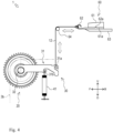
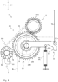
- the warp feeding device 1 according to the sixth embodiment is different from the warp feeding device 1 according to the first embodiment in further including a slack eliminating mechanism 200. Hereinafter, this difference will be described.
- the slack eliminating mechanism 200 is provided to eliminate the slack of this warp 3b, and includes a first magnet portion 210, a second magnet portion 220, and a shielding member 230.
- the first magnet portion 210 is a magnet provided in the second driven roller 52, and is formed in a cuboid shape.
- a plurality of the first magnet portions 210 are provided with the longitudinal direction oriented in the radial direction of the second driven roller 52.
- the first magnet portions 210 are provided at equal intervals to one another in the circumferential direction of the second driven roller 52. In the present embodiment, six of the first magnet portions 210 are provided at intervals of 60° from one another.
- the first magnet portion 210 is provided such that the radially outer surface thereof is substantially at the same position as the outer peripheral surface of the second driven roller 52 in a side view.
- the first magnet portion 210 includes an S pole portion 211 and an N pole portion 212.
- the S pole portion 211 is disposed counterclockwise in a right side view of the first magnet portion 210. Specifically, the S pole portion 211 is provided so as to be positioned in a front side part of the first magnet portion 210 when the second driven roller 52 rotates and the first magnet portion 210 is positioned at the uppermost position.
- the N pole portion 212 is disposed clockwise in a right side view of the first magnet portion 210. Specifically, the N pole portion 212 is provided so as to be positioned in a rear side part of the first magnet portion 210 when the second driven roller 52 rotates and the first magnet portion 210 is positioned at the uppermost position. The N pole portion 212 is provided so as to be adjacent to the S pole portion 211.
- the second magnet portion 220 is a magnet provided independently of the second driven roller 52, and is fixed to the flat knitting machine 2 below the second driven roller 52. More specifically, the second magnet portion 220 is provided such that the front-rear center thereof is positioned slightly behind the center of the second driven roller 52.
- the second magnet portion 220 is formed in a substantially rectangular shape in a side view.
- the second magnet portion 220 includes the S pole portion 221 and the N pole portion 222.
- the S pole portion 221 is provided so as to constitute a rear side part of the second magnet portion 220.
- the N pole portion 222 constitutes a front side part of the second magnet portion 220, and is provided so as to be adjacent to the S pole portion 221.
- the N pole portion 222 is provided at a position closer to the second driven roller 52 than the S pole portion 221.
- the shielding member 230 shields or demagnetizes the magnetic force of the first magnet portion 210. More specifically, the shielding member 230 shields the magnetic force acting to rotate the second driven roller 52 in the opposite direction with respect to the second magnet portion 220.
- the shielding member 230 is formed of an iron piece that is a ferromagnetic material, and is provided so as to cover a magnetic pole surface of the N pole portion 212 of the first magnet portion 210.
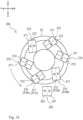
- Fig. 10(a) illustrates a state where slack of the warp 3b occurs on a downstream side relative to the driving roller 20 due to a feeding error or the like.
- the attraction force by the N pole portion 222 of the second magnet portion 220 acts on an S pole portion 211a of a first magnet portion 210a positioned at the front lower part among the six first magnet portions 210.
- the second driven roller 52 does not rotate in the winding direction even if the attraction force by the N pole portion 222 acts on the S pole portion 211a by the action of the ratchet mechanism 32.
- the magnetic pole surface of an N pole portion 212b of a first magnet portion 210b positioned in the rear lower part among the six first magnet portions 210 is covered with the shielding member 230. Therefore, the attraction force of the N pole portion 212b with respect to the S pole portion 221 is shielded or demagnetized. Therefore, the second driven roller 52 is suppressed from rotating in the direction opposite to the winding direction.
- the driving roller 20 rotates in the reverse direction. Due to this, the warps 3b on the downstream side of the driving roller 20 are wound, and the slack of the warps 3b can be eliminated.
- the endless belt 53 also operates in the direction of winding the warps 3b. Therefore, the warps 3b can be wound in a state where the warps 3b are sandwiched between the peripheral surface 20a of the driving roller 20 and the outer peripheral surface of the endless belt 53.
- the slack eliminating mechanism 200 uses a magnetic force for winding the warps 3b. Therefore, unlike a case of torque application by physical connection, for example, problems such as wear between members do not occur, and maintainability and durability can be improved.
- the warp feeding device 1 according to the seventh embodiment is different from the warp feeding device 1 according to the sixth embodiment in that the disposition of the first magnet portion 210 of the slack eliminating mechanism 200 is different. Hereinafter, this difference will be described.
- the first magnet portion 210 is provided in a state where the longitudinal direction thereof is inclined with respect to the radial direction of the second driven roller 52. More specifically, the first magnet portion 210 is provided such that the S pole portion 211 faces the outer diameter side of the N pole portion 212.
- the magnetic pole surface of an S pole portion 211c of a first magnet portion 210c positioned at the front lower part of the six first magnet portions 210 substantially faces the N pole portion 222 of the second magnet portion 220.
- the magnetic pole surface of an N pole portion 212d of a first magnet portion 210d positioned in the rear lower part among the six first magnet portions 210 does not face the S pole portion 221 of the second magnet portion 220. Therefore, the second driven roller 52 rotates in the winding direction by the attraction force of the S pole portion 211c and the N pole portion 222.
- the driving roller 20 rotates in the reverse direction. Due to this, the warps 3b on the downstream side of the driving roller 20 are wound, and the slack of the warps 3b can be eliminated.
- the feeding amount of the warp 3b per course is about 3.5 mm, and the feeding error is estimated to be about ⁇ 0.1 to 0.2 mm.
- the winding amount per one time is about 2 to 3 mm, even if "no winding" of +0.2 mm occurs for consecutively 10 times, for example, the accumulated feeding error can be eliminated by one winding.
- the second magnet portion 220 is fixed to the flat knitting machine 2, but similarly to the first magnet portion 210, the magnets may be provided in the roller at equal intervals in the circumferential direction, and may be configured to always rotate to generate a force for rotating the second driven roller 52 in the winding direction.
- this force is set to be smaller than the rotational force of the driving roller 20 when feeding the warps 3b to the downstream side, and is set so as not to hinder the feeding of the warps 3b.
- first magnet portions 210 are provided, but the number of first magnet portions 210 may be discretionary.
- the present invention can be applied to a warp feeding device that feeds a warp to a flat knitting machine.
Landscapes
- Engineering & Computer Science (AREA)
- Textile Engineering (AREA)
- Knitting Machines (AREA)
Abstract
Description
- The present invention relates to a technique of a warp feeding device that feeds a warp to a flat knitting machine.
- Conventionally, a technique of a warp feeding device that feeds a warp to a flat knitting machine is known. For example,
Patent Literature 1 discloses such technique. -
Patent Literature 1 discloses a technique for sandwiching a warp and a weft between flat knitted knitting yarns. Specifically, inPatent Literature 1, a plurality of first base yarns (warps) arranged in parallel in the knitting width direction and a second base yarn (weft) arranged in parallel in a longitudinal direction intersecting the first base yarns are sandwiched by flat knitting a knitting yarn. - In a fabric knitted as described above, the weft is inserted by inlay or the like in the knitting width direction by, for example, a yarn feeder, and is reliably knitted. On the other hand, the warp is fed from above the knitting machine, for example, and is basically knitted down together with the fabric depending on the friction between the weft and the knitting yarn. That is, feeding of the warp to the knitting machine is passively carried out. In such a case, for example, if the tension due to the release resistance at the time of taking out the warp from a yarn source reel or the tension due to the downward deflection due to the own weight of the warp is high, a necessary amount is not knitted down, and intervals between the wefts arranged in parallel in the longitudinal direction are reduced. Reduction in the intervals between the wefts causes strength unevenness to occur in a case where the fabric is used as a base material of FRP.
- In order to individually feed the warps, it is necessary to provide a large number of feeding rollers, and in this case, a large number of warps are passed from a creel stand to the knitting machine. Therefore, there has been a problem of complication around the yarn feeding path and difficulty in direct drive of the feeding roller.
- Patent Literature 1:
JP 2014-34737 A - The present invention has been made in view of the above circumstance, and an object thereof is to provide a warp feeding device that can make a warp easily knitted down and suppress complication around a yarn feeding path.
- The problem to be solved by the present invention is as described above, and means for solving the problem will be described below.
- That is, a warp feeding device according to the present invention is a warp feeding device that feeds a warp from above to a flat knitting machine, the warp feeding device including: a drive source that generates a driving force; a driving roller rotatably provided below the drive source, the driving roller having a peripheral surface in contact with the warp fed from a yarn source so as to bend a yarn feeding direction downward; and a transmission mechanism that transmits the driving force so as to rotate the driving roller only in one direction and feeds the warp downward.
- Such a configuration can actively carry out feeding of the warp to the flat knitting machine by the rotation of the driving roller using the driving force from the drive source, and therefore can make a warp easily knitted down. The drive source is disposed higher than the driving roller, that is, relatively far from the driving roller, whereby complication around the yarn feeding path can be suppressed.
- A plurality of driven rollers rotatable with rotation of the driving roller; and a belt that is endless, is spanned over the plurality of driven rollers, and having an outer peripheral surface in contact with the peripheral surface of the driving roller are further included, and the driving roller sandwiches the warp between the peripheral surface and the outer peripheral surface of the belt, and feeds the warp downward.
- Such a configuration sandwiches and feeds the warp by the driving roller and the belt, and thus can suppress the warp from being broken, for example, even if the warp is not twisted as a carbon fiber, and can more suitably feed the warp to the flat knitting machine.
- The transmission mechanism includes a coupling member that is coupled integrally rotatably in the one direction with the driving roller and relatively rotatably in another direction with respect to the driving roller, and the driving roller feeds the warp downward by rocking of the coupling member caused by the driving force.
- Such a configuration can continuously carry out feeding of the warp to the flat knitting machine with a relatively simple configuration.
- The transmission mechanism includes a rack portion that can reciprocate due to the driving force, and
a pinion gear that is provided to be engaged with the rack portion, is integrally rotatable in the one direction with the driving roller due to reciprocation of the rack portion, and is relatively rotatable in another direction with respect to the driving roller, and the driving roller rotates in the one direction due to the driving force transmitted through the pinion gear, and feeds the warp downward. - Such a configuration can feed the warp to the flat knitting machine using a rack and pinion.
- The drive source is a motor whose rotation amount is adjustable.
- Such a configuration can adjust the amount of warp to be fed to the knitting machine as necessary. Specifically, for example, the amount of the warp of one part in the knitting width direction of the fabric can be increased or decreased compared to another part.
- The drive source is a moving body including a cam mechanism that can move in accordance with knitting by a carriage of the flat knitting machine and can generate a driving force with movement.
- Such a configuration can achieve relatively space saving and cost reduction.
- As an effect of the present invention, it is possible to make a warp easily knitted down.
-
-
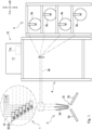
Fig. 1 is a schematic side view illustrating a yarn feeding mechanism applied with a warp feeding device according to a first embodiment of the present invention. -
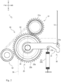
Fig. 2 is a side view illustrating the warp feeding device. -
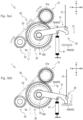
Fig. 3 is a side view illustrating an operation of the warp feeding device, and is (a) a view illustrating a state where a lever pivots upward. (b) a view illustrating a state where the lever pivots downward. -
Fig. 4 is a side view illustrating a warp feeding device according to a second embodiment. -
Fig. 5 is a side view illustrating a warp feeding device according to a third embodiment. -
Fig. 6 is a side view illustrating a warp feeding device according to a fourth embodiment. -
Fig. 7 is a side view illustrating a warp feeding device according to a fifth embodiment. -
Fig. 8 is a side view illustrating a warp feeding device according to a sixth embodiment, the warp feeding device including a slack eliminating mechanism. -
Fig. 9 is a side view illustrating the slack eliminating mechanism. -
Fig. 10 is a side view illustrating the operation of the slack eliminating mechanism, and is (a) a view illustrating a state where the warp is slack. (b) is a view illustrating a state where the warp is wound and yarn slack is eliminated. -
Fig. 11 is a side view illustrating a warp feeding device according to a seventh embodiment, the warp feeding device including a slack eliminating mechanism of another example. - In the following, description will be given with directions indicated by arrow U, arrow D, arrow F, and arrow B in the drawing defined as an upward direction, a downward direction, a forward direction, and a backward direction, respectively. Description will be given with a front direction on the paper surface and a depth direction on the paper surface in the side view of
Fig. 1 and the like defined as a right direction and a left direction, respectively. The left-right direction corresponds to the knitting width direction of aflat knitting machine 2. In the drawings, illustration of each component is appropriately omitted for simplification of illustration. - As illustrated in
Fig. 1 , awarp feeding device 1 according to an embodiment of the present invention feeds awarp 3b used for knitting of a fabric to theflat knitting machine 2. Theflat knitting machine 2 can knit a fabric by fixing, by flat knitting the knitting yarns, a plurality of thewarps 3b arranged in parallel in a knitting width direction and a weft arranged in parallel in a longitudinal direction intersecting thewarps 3b. In the fabric, the weft is inserted as an inlay yarn. Thus, thewarps 3b and the weft do not constitute a stitch, and are fixed to each other by friction by being sandwiched by a knitting yarn as a retaining yarn. Acreel stand 3 is provided behind theflat knitting machine 2. A plurality ofyarn source reels 3a around which thewarps 3b are wound are housed in thecreel stand 3. When theflat knitting machine 2 knits the fabric, thewarps 3b wound around theyarn source reels 3a are fed to theflat knitting machine 2 through thewarp feeding device 1. As thewarp 3b, for example, a bundle of a plurality of reinforcing fibers (e.g., carbon fibers) is used. - The
flat knitting machine 2 includes afront needle bed 2a and arear needle bed 2b so as to face front and rear across aneedle bed gap 2c. In theflat knitting machine 2, a hook of a knitting needle not illustrated advances and retreats to theneedle bed gap 2c from the distal end side of thefront needle bed 2a or therear needle bed 2b. A weft and a knitting yarn are fed from a plurality of yarn feeders (not illustrated) to theneedle bed gap 2c. - The
flat knitting machine 2 includes awarp pipe 2d that can simultaneously feed the plurality ofwarps 3b when knitting the fabric. Thewarp pipes 2d are arranged in three rows in the front-rear direction and in a plurality of rows in the knitting width direction by the number of thewarps 3b to be knitted. Thewarp pipe 2d is disposed at a position not interfering with the yarn feeder moving in the knitting width direction, and feeds each of thewarps 3b to theneedle bed gap 2c from above by passing thewarps 3b therein. - Hereinafter, the configuration of the
warp feeding device 1 will be described with reference toFigs. 1 to 3 . Hereinafter, there is a case where theyarn source reel 3a side of the yarn feeding path of thewarp 3b is referred to as "upstream side", and theflat knitting machine 2 side is referred to as "downstream side". - The
warp feeding device 1 feeds the plurality ofwarps 3b used for knitting of the fabric to theflat knitting machine 2 by controlling a feeding amount for each of thewarps 3b. Thewarp feeding device 1 mainly includes a drivingdevice 10, a drivingroller 20, atransmission mechanism 30, anoperation regulation portion 40, and a drivenmechanism 50. - The driving
device 10 illustrated inFig. 1 drives the drivingroller 20 described later through thetransmission mechanism 30 described later. The drivingdevice 10 includes ajacquard shedding machine 11 and aharness 12. - The
jacquard shedding machine 11 illustrated inFig. 1 serves as a drive source for the operation of thewarp feeding device 1 when feeding each of thewarps 3b to theflat knitting machine 2. Thejacquard shedding machine 11 individually controls the feeding amount of each of thewarps 3b. As thejacquard shedding machine 11, for example, a known jacquard shedding machine used in a general shuttle loom can be employed. Thejacquard shedding machine 11 performs control based on a program incorporated in advance. Thejacquard shedding machine 11 is disposed on a table 4 disposed between theflat knitting machine 2 and thecreel stand 3. Thejacquard shedding machine 11 is disposed higher than theflat knitting machine 2. Thejacquard shedding machine 11 is disposed higher than the drivingroller 20, thetransmission mechanism 30, theoperation regulation portion 40, and the drivenmechanism 50, which will be described later. Thejacquard shedding machine 11 includes amotor 11a. - The
motor 11a generates a driving force. Themotor 11a is provided so that the rotation amount can be adjusted, and the displacement amount of theharness 12 described later can be adjusted by adjustment of the rotation amount. A plurality of themotors 11a are provided. More specifically, themotors 11a are provided for therespective warps 3b. Themotor 11a originally included in thejacquard shedding machine 11 can be used. The operation of themotor 11a is controlled by a control unit not illustrated. - The
harness 12 illustrated inFigs. 1 to 3 is for vertically pivoting alever 31 described later. Oneharness 12 is provided for eachmotor 11a. An upper end part of theharness 12 is connected to themotor 11a through an appropriate member. A lower end part of theharness 12 is connected to thelever 31 described later. Theharness 12 is provided so as to extend forward from themotor 11a and be bent downward by a direction changing member not illustrated. - In the driving
device 10 configured as described above, a plurality of theharnesses 12 can be individually displaced upward or downward by driving eachmotor 11a in accordance with individually preset patterns. - The driving
roller 20 illustrated inFigs. 2 and3 feeds thewarps 3b to the downstream side. The drivingroller 20 is provided on the yarn feeding path of thewarp 3b rotatably about an axis extending in the left-right direction. The drivingroller 20 is provided for each of thewarps 3b. As illustrated inFig. 1 , the drivingrollers 20 adjacent in the knitting width direction are disposed with the height shifted from one another in order to secure an arrangement space. - The
warp 3b fed out from the rear of the driving roller 20 (theyarn source reel 3a housed in the creel stand 3) is fed to the upper end part of aperipheral surface 20a of the drivingroller 20. Thewarp 3b is fed to theperipheral surface 20a from a direction along a tangential direction of the upper end part of theperipheral surface 20a. Thewarp 3b is brought into contact with theperipheral surface 20a, and guided so as to be bent downward by theperipheral surface 20a. - The outer peripheral surface of the driving
roller 20 is provided with a plurality ofteeth 20b over the entire periphery. The plurality ofteeth 20b are provided at equal intervals to one another in the circumferential direction. - The driving
roller 20 configured as described above can feed thewarps 3b to the downstream side by rotating counterclockwise in the right side view illustrated inFigs. 2 and3 . Hereinafter, regarding the rotation direction of the drivingroller 20, there is a case where a counterclockwise direction in a right side view, that is, a direction in which thewarps 3b are fed to the downstream side is referred to as "forward direction", and a clockwise direction in a right side view, which is a direction opposite to the forward direction, is referred to as a "reverse direction". - The
transmission mechanism 30 illustrated inFigs. 2 and3 transmits the driving force from the drivingdevice 10 to the drivingroller 20. Thetransmission mechanism 30 includes thelever 31 and aratchet mechanism 32. - The
lever 31 is for rotating the drivingroller 20, and is provided pivotally (rockably up and down) coaxially with the drivingroller 20. Thelever 31 is provided so as to extend in the longitudinal direction substantially rearward from a pivot center. Thelever 31 includes afirst hook portion 31a and asecond hook portion 31b. - The
first hook portion 31a is a portion on which theharness 12 is hooked, and is formed in a substantially inverted U-shaped hook shape. Thefirst hook portion 31a is formed at the rear end part of thelever 31. - The
second hook portion 31b is a portion on which aspring 41 described later is hooked, and is formed in a substantially U-shaped hook shape. Thesecond hook portion 31b is formed in a front-rear middle portion of the lever 31 (forward relative to thefirst hook portion 31a). - The
ratchet mechanism 32 regulates a rotation direction of the drivingroller 20, is incorporated in a pivot center part of thelever 31, and is formed to pivot along with the pivot of thelever 31. Theratchet mechanism 32 is formed so as to be engaged with the drivingroller 20 when thelever 31 pivots upward, but not to be engaged with the drivingroller 20 when thelever 31 pivots downward. - That is, the driving
roller 20 rotates in the forward direction along with upward pivot of thelever 31 by theratchet mechanism 32. On the other hand, the drivingroller 20 does not rotate in the reverse direction along with downward pivot of thelever 31 by theratchet mechanism 32. - The
operation regulation portion 40 illustrated inFigs. 2 and3 regulates or controls the operation of thelever 31, and includes thespring 41 and a movementrange regulation portion 42. - The
spring 41 biases thelever 31 downward, and a tension coil spring is used. The upper end of thespring 41 is fixed to thesecond hook portion 31b of thelever 31. The lower end of thespring 41 is fixed to a discretionary part of thewarp feeding device 1. The discretionary part is a part that does not move even when thelever 31 pivots. - The movement
range regulation portion 42 illustrated inFig. 3 regulates a pivot range of thelever 31, and includes anupper regulation portion 42a and alower regulation portion 42b. - The
upper regulation portion 42a regulates an upward pivot range of thelever 31, and is provided above thelever 31. More specifically, theupper regulation portion 42a is formed at a position in contact with thelever 31 when thelever 31 pivots upward by a predetermined angle, and regulates the upward pivot range of thelever 31. - The
lower regulation portion 42b regulates a downward pivot range of thelever 31, and is provided below thelever 31. More specifically, thelower regulation portion 42b is formed at a position in contact with thelever 31 when thelever 31 pivots downward by a predetermined angle, and regulates the downward pivot range of thelever 31. - Here, when the driving
roller 20 is rotated, theharness 12 operates linearly, whereas thelever 31 operates in an arc shape. Therefore, when the stroke of theharness 12 becomes too large, the displacement amount of theharness 12 and the feeding amount of thewarps 3b are not proportional. Therefore, in thewarp feeding device 1 according to the present embodiment, the movementrange regulation portion 42 regulates the pivot range of thelever 31. The upward pivot range of thelever 31 is regulated, whereby it is possible to suppress plastic deformation of thespring 41. - The driven
mechanism 50 illustrated inFigs. 2 and3 operates with the rotation of the drivingroller 20, and includes a first drivenroller 51, a second drivenroller 52, and anendless belt 53. - The first driven
roller 51 is provided rotatably about an axis extending in the left-right direction, and is disposed substantially above the drivingroller 20. - The outer peripheral surface of the first driven
roller 51 is provided with a plurality ofteeth 51a over the entire periphery of the outer peripheral surface of the first drivenroller 51. The plurality ofteeth 51a are provided at equal intervals to one another in the circumferential direction. The first drivenroller 51 is provided such that theteeth 51a mesh with theteeth 20b of the drivingroller 20. Due to this, the first drivenroller 51 rotates with the rotation of the drivingroller 20. - The second driven
roller 52 is provided rotatably about an axis extending in the left-right direction, in lower front of the first drivenroller 51 and substantially in front of the drivingroller 20. The second drivenroller 52 rotates with the rotation of the first drivenroller 51 through theendless belt 53 described later. - The
endless belt 53 is provided so as to span over the first drivenroller 51 and the second drivenroller 52 and so as to have the outer peripheral surface in contact with the drivingroller 20. More specifically, the outer peripheral surface of theendless belt 53 is provided so as to abut on a part of theperipheral surface 20a of the drivingroller 20 that comes into contact with thewarps 3b. - Hereinafter, the operation of the
warp feeding device 1 when feeding thewarps 3b to theflat knitting machine 2 will be described with reference toFig. 3 . - When feeding the
warps 3b to theflat knitting machine 2, themotor 11a of the drivingdevice 10 is first driven to displace theharness 12 upward by a predetermined amount. Then, as illustrated inFig. 3(a) , thelever 31 connected to theharness 12 pivots upward and rotates the drivingroller 20 in the forward direction. Due to this, thewarps 3b are fed to the downstream side. The displacement amount of theharness 12 that determines the feeding amount of thewarps 3b is set in consideration of the amount necessary for knitting of the fabric. - Here, as described above, since the
teeth 51a are provided to mesh with theteeth 20b of the drivingroller 20, the first drivenroller 51 rotates clockwise in a right side view with rotation in the forward direction of the drivingroller 20. Then, the second drivenroller 52 connected to the first drivenroller 51 through theendless belt 53 also rotates clockwise in a right side view. - Due to this, the driving
roller 20 can feed thewarps 3b downward in a state where thewarps 3b are sandwiched between theperipheral surface 20a and the outer peripheral surface of theendless belt 53. By doing so, thewarps 3b are less likely to come off from the drivingroller 20, and thewarps 3b can be reliably fed downstream. It is possible to suppress only a part of the plurality of reinforcing fibers constituting thewarps 3b that is in contact with theperipheral surface 20a from being fed to the downstream side. Even if thewarps 3b are only a bundle of carbon fibers and are not twisted yarns, thewarps 3b can be suppressed from being broken, and thewarps 3b can be more suitably fed to theflat knitting machine 2. - On the other hand, when the upward driving force of the
harness 12 is released, as illustrated inFig. 3(b) , thelever 31 connected to theharness 12 pivots downward by the biasing force of thespring 41. However, even when thelever 31 pivots downward by the action of theratchet mechanism 32, the drivingroller 20 does not rotate in the reverse direction. Therefore, thewarps 3b can be suppressed from being returned to the upstream side. - In this manner, by rotating the driving
roller 20 using the driving force from the drivingdevice 10, thewarp feeding device 1 can actively feed each of thewarps 3b used for knitting of the fabric to theflat knitting machine 2. Due to this, thewarps 3b can be knitted down by an amount necessary for the knitting of the fabric against the tension (tension due to release resistance at the time of taking out thewarps 3b from theyarn source reel 3a or tension due to downward deflection due to the own weight of thewarps 3b) applied to thewarps 3b. Therefore, it is possible to suppress the interval between the wefts arranged in parallel in the longitudinal direction from being reduced. Feeding of thewarps 3b to theflat knitting machine 2 can be continuously carried out with the relatively simple configuration such as the drivingroller 20 and thetransmission mechanism 30. - A large number of the driving
rollers 20 need to be disposed in the knitting width direction in order to individually control thewarps 3b, and in this case, a large number of warps pass from the creel stand to the knitting machine. Therefore, the degree of freedom of disposition of the drivingdevice 10 is relatively low. Therefore, in the present embodiment, by disposing the drivingdevice 10 for rotating the drivingroller 20 at a position relatively distant from theflat knitting machine 2, a large number of thewarps 3b can be individually and actively fed without complicating around the yarn feeding path. More specifically, by configuring not such that the drivingdevice 10 directly rotates the drivingroller 20 but such that the drivingdevice 10 and thelever 31 are coupled through theharness 12, the drivingdevice 10 does not need to be disposed around the yarn feeding path, and the drivingdevice 10 can be disposed at a position relatively distant from theflat knitting machine 2. Therefore, it is possible to suppress complication around the yarn feeding path. - Since the feeding amount of each of the
warps 3b can be individually adjusted using eachmotor 11a of thejacquard shedding machine 11, for example, the amount of thewarps 3b of one part in the knitting width direction of the fabric can be increased or decreased as compared with another part. - Although an embodiment of the present invention has been described above, the present invention is not limited to the above embodiment, and appropriate changes can be made within the scope of the technical idea of the invention described in the claims.
- For example, in the present embodiment, the
flat knitting machine 2 in which thewarp feeding device 1 feeds thewarp 3b is configured to knit the fabric by fixing thewarps 3b and the weft using a knitting yarn, but may be configured to knit the fabric without using the weft. Specifically, as illustrated inFig. 1 ofJapanese Patent No. 5955197 flat knitting machine 2 may sandwich the warp depending on a positional relationship between the knitting yarn and the warp fed from two carriers that move the front and back phases with respect to the warp. - The
warps 3b are fed to the upper end part of theperipheral surface 20a of the drivingroller 20, but thewarps 3b may be fed to a part at rear relative to the upper end part of theperipheral surface 20a, pass through the upper end part of theperipheral surface 20a, and then be guided so as to bend downward by theperipheral surface 20a. Due to this, the length of thewarp 3b in contact with theperipheral surface 20a increases, and therefore slippage of thewarps 3b with respect to theperipheral surface 20a can be reduced, and the feeding accuracy of thewarps 3b can be improved. - Each of the
warps 3b is fed to theflat knitting machine 2 by a necessary amount for the next course at a timing when the knitting direction is reversed. Thus, thewarps 3b are sent to theflat knitting machine 2 at the same timing. The present invention is not limited to this, and thewarps 3b fixed with the retaining yarn by the knitting needle may be fed to theflat knitting machine 2 at a timing, for example, when each knitting needle advances to theneedle bed gap 2c. That is, thewarps 3b may be fed to theflat knitting machine 2 at different timings. - In the present embodiment, the
motor 11a is used as the drive source, but a solenoid may be used. - In the present embodiment, the
ratchet mechanism 32 regulates the rotation direction of the drivingroller 20, but any configuration may be used as long as force can be transmitted only in one direction and force is not transmitted in another direction, and for example, a one-way clutch may be used. - Next, the configuration of the
warp feeding device 1 according to the second embodiment of the present invention will be described with reference toFig. 4 . - The
warp feeding device 1 according to the second embodiment is different from thewarp feeding device 1 according to the first embodiment in including adriving device 60 in place of the drivingdevice 10. Hereinafter, this difference will be described. InFig. 4 andFigs. 5 to 7 described later, the drivenmechanism 50 is not illustrated. - The driving
device 60 includes theharness 12, a movingbody 61, a needle-shapedbody 62, aneedle bed 63, and adirection changing roller 64. Note that theharness 12 is the same as that of the first embodiment, and thus the description thereof is omitted. - The moving
body 61 can reciprocate in the knitting width direction in synchronization with a carriage (not illustrated) of theflat knitting machine 2, and is driven by a motor and a timing belt that are not illustrated. The lower surface of the movingbody 61 is provided with acam surface 61a. - The needle-shaped
body 62 is formed in a needle shape whose longitudinal direction is oriented in the front-rear direction, and is provided for eachharness 12. The front end of the needle-shapedbody 62 is formed in a hook shape, and theharness 12 is engaged. The needle-shapedbody 62 includes abat 62a formed such that a front-rear middle portion protrudes upward. A plurality of needle-shapedbodies 62 are provided on theneedle bed 63 so as to be arranged in the left-right direction. - The driving
device 60 includes an actuator (not illustrated), and is configured to be able to switch the needle-shapedbody 62 between a needle selection state and a non-needle selection state by the actuator. The switching between the needle selection state and the non-needle selection state is determined based on a program incorporated in advance. In the needle selection state, when the movingbody 61 moves in the knitting width direction, thebat 62a is guided by thecam surface 61a, whereby the needle-shapedbody 62 advances and retreats back and forth. On the other hand, in the needle-shapedbody 62, in the non-needle selection state, thebat 62a is sunk in theneedle bed 63. Therefore, even if the movingbody 61 moves in the knitting width direction, thebat 62a is not guided by thecam surface 61a. Therefore, the needle-shapedbody 62 does not advance and retreat back and forth. In this manner, thecam surface 61a generates a driving force for moving the needle-shapedbody 62 with the movement of the movingbody 61. - The
direction changing roller 64 changes the direction of theharness 12, and is formed to change the extending direction of theharness 12 so as to bend and extend downward theharness 12 extending forward from the front end of the needle-shapedbody 62. - In the
warp feeding device 1 according to the second embodiment configured as described above, when the movingbody 61 reciprocates in the knitting width direction in synchronization with the carriage of theflat knitting machine 2, only the needle-shapedbody 62 in the needle selection state advances and retreats back and forth. Due to this, theharness 12 is displaced up and down, and thelever 31 is pivoted upward. This can rotate the drivingroller 20 in the forward direction and feed thewarps 3b on the downstream side. - By driving the driving
roller 20 using thedriving device 60 configured as described above, it is possible to achieve relatively space saving and cost reduction. - Next, the configuration of the
warp feeding device 1 according to the third embodiment of the present invention will be described with reference toFig. 5 . - The
warp feeding device 1 according to the third embodiment is different from thewarp feeding device 1 according to the first embodiment in including adriving device 70 in place of the drivingdevice 10. Hereinafter, this difference will be described. - The driving
device 70 includes the movingbody 61, a needle-shapedbody 72, aneedle bed 73, anactuation link 74, and anactuation bar 75. Note that the movingbody 61 is the same as that of the second embodiment, and thus the description thereof is omitted. The needle-shapedbody 72 and theneedle bed 73 correspond to the needle-shapedbody 62 and theneedle bed 63 of the second embodiment, respectively. - The
actuation link 74 constitutes a part of the link mechanism, and includes apivot member 74a, afirst connection portion 74b, and asecond connection portion 74c. - The
pivot member 74a is formed rotatably about an axis extending in the left-right direction. Thepivot member 74a is connected rockably to the front end part of the needle-shapedbody 72 by thefirst connection portion 74b, and is connected rockably to the upper end part of theactuation bar 75 described later by thesecond connection portion 74c. - The
actuation bar 75 operates thelever 31, is formed in a rod shape made of a material such as metal or resin, and is provided with the longitudinal direction oriented in the up-down direction. As described above, theactuation bar 75 has the upper end connected to thepivot member 74a, and the lower end connected to thefirst hook portion 31a of thelever 31. - In the
warp feeding device 1 according to the third embodiment configured as described above, when the needle-shapedbody 72 in the needle selection state advances and retreats with the reciprocation movement in the knitting width direction of the movingbody 61, theactuation link 74 pivots to vertically displace theactuation bar 75. More specifically, when the needle-shapedbody 72 moves backward and theactuation link 74 pivots clockwise in a right side view, theactuation bar 75 is displaced upward and pivots thelever 31 upward. This can rotate the drivingroller 20 in the forward direction and feed thewarps 3b on the downstream side. - In the example illustrated in
Fig. 5 , thelever 31 is biased downward by thespring 41, but thespring 41 is not necessarily included because thelever 31 can be displaced also downward by the pivot of theactuation link 74. The same applies to the example illustrated inFig. 6 described later. - In
Fig. 5 , thefirst connection portion 74b and thesecond connection portion 74c are illustrated to have substantially the same length, but for example, the length of thesecond connection portion 74c may be longer than the length of thefirst connection portion 74b. This can increase the displacement amount of theactuation bar 75 with respect to the advancing and retracting movement amount of the needle-shapedbody 72, and eventually can downsize the cam mechanism. - Next, the configuration of the
warp feeding device 1 according to the fourth embodiment of the present invention will be described with reference toFig. 6 . - The
warp feeding device 1 according to the fourth embodiment is different from thewarp feeding device 1 according to the first embodiment in including adriving device 80 in place of the drivingdevice 10. Hereinafter, this difference will be described. - The driving
device 80 includes the movingbody 61, the needle-shapedbody 72, theneedle bed 73, aslide member 84, and anactuation bar 86. Note that the movingbody 61 is the same as that of the second embodiment, and thus the description thereof is omitted. Note that the needle-shapedbody 72 and theneedle bed 73 are the same as those of the third embodiment, and thus the description is omitted. - The
slide member 84 is a member provided slidably back and forth and fixed to the front end part of the needle-shapedbody 72. Due to this, theslide member 84 reciprocates back and forth with advance and retreat movement back and forth of the needle-shapedbody 72. Theslide member 84 is provided with along hole 84a formed such that the longitudinal direction is oblique with respect to the front-rear direction. More specifically, thelong hole 84a is formed to be inclined so as to be positioned downward as it goes rearward. - The configuration of the
actuation bar 86 is substantially the same as that of theactuation bar 75 of the third embodiment. Theactuation bar 86 is guided by a guide member not illustrated so as not to move in the front-rear direction, that is, so as to be movable only in the up-down direction. The upper end of theactuation bar 86 is provided with apin 86a. Thepin 86a is formed so as to extend leftward from the upper end of theactuation bar 86, and is inserted into thelong hole 84a of theslide member 84. - In the
warp feeding device 1 according to the fourth embodiment configured as described above, when the needle-shapedbody 72 in the needle selection state advances and retreats with the reciprocation movement in the knitting width direction of the movingbody 61, theslide member 84 reciprocates back and forth, and thepin 86a is guided to thelong hole 84a. Then, theactuation bar 86 is displaced upward, and thelever 31 is pivoted upward. This can rotate the drivingroller 20 in the forward direction and feed thewarps 3b on the downstream side. - Although the second embodiment to the fourth embodiment of the present invention have been described above, the present invention is not limited to the above embodiments, and appropriate changes can be made within the scope of the technical idea of the invention described in the claims.
- For example, as long as the moving
body 61 operates in accordance with the knitting by the carriage of theflat knitting machine 2, the movingbody 61 is not limited to one that operates in synchronization with the carriage of theflat knitting machine 2 as in the second to fourth embodiments, and may be one that operates prior to the operation of the carriage. - Although the inclination angle of the
long hole 84a can be discretionary, thelong hole 84a may be formed so that the inclination angle with respect to the horizontal direction becomes relatively large, that is, the long hole may be formed to be relatively vertically long. This can increase the displacement amount of theactuation bar 86 with respect to the advancing and retracting movement amount of the needle-shapedbody 72, and eventually can downsize the cam mechanism. - As the driving device, a combination of the
jacquard shedding machine 11 of the first embodiment and the mechanism illustrated inFigs. 5 and6 may be used. - Next, the configuration of the
warp feeding device 1 according to the fifth embodiment of the present invention will be described with reference toFig. 7 . - The
warp feeding device 1 according to the fifth embodiment is different from thewarp feeding device 1 according to the first embodiment in including atransmission mechanism 90 in place of thetransmission mechanism 30. Hereinafter, this difference will be described. - The
transmission mechanism 90 includes apinion gear 91, aratchet mechanism 92, and arack 93. - The
pinion gear 91 is for rotating the drivingroller 20, and is provided on the right side of the drivingroller 20 rotatably coaxially with the drivingroller 20. The outer peripheral surface of thepinion gear 91 is provided with a plurality ofteeth 91a over the entire periphery. The plurality ofteeth 91a are provided at equal intervals to one another in the circumferential direction. - The
ratchet mechanism 92 regulates the rotation direction of the drivingroller 20, is incorporated in a rotation center part of thepinion gear 91, and is formed to pivot with the rotation of thepinion gear 91. Theratchet mechanism 92 is formed so as to be engaged with the drivingroller 20 when thepinion gear 91 rotates counterclockwise in a right side view, but not to be engaged with the drivingroller 20 when thepinion gear 91 rotates clockwise in a right side view. - That is, by the
ratchet mechanism 92, the drivingroller 20 rotates in the forward direction with the rotation of thepinion gear 91 counterclockwise in a right side view. On the other hand, by theratchet mechanism 92, the drivingroller 20 does not rotate in the reverse direction with the rotation of thepinion gear 91 clockwise in a right side view. - The
rack 93 is for rotating the drivingroller 20, and is provided at rear of the drivingroller 20 with the longitudinal direction oriented in the up-down direction. Therack 93 is guided by a guide member not illustrated so as not to move in the front-rear direction, that is, so as to be movable only in the up-down direction. - The front surface of the
rack 93 is provided with a plurality ofteeth 93a at equal intervals with one another in the up-down direction. Therack 93 is provided such that theteeth 93a mesh with theteeth 91a of thepinion gear 91. - The
rack 93 has the upper end connected with the lower end of theharness 12. Therack 93 has the lower end engaged with the upper end of thespring 41, and is biased downward by thespring 41. - In the
warp feeding device 1 according to the fifth embodiment configured as described above, when themotor 11a of the drivingdevice 10 is driven to displace theharness 12 upward by a predetermined amount, therack 93 connected to theharness 12 moves upward. Here, as described above, therack 93 is provided such that theteeth 93a mesh with theteeth 91a of thepinion gear 91. Therefore, when therack 93 moves upward, thepinion gear 91 rotates counterclockwise in a right side view along with this, and the drivingroller 20 rotates in the forward direction. This can feed thewarps 3b on the downstream side. - By adjusting the gear ratio, the feeding amount of the driving
roller 20 can be made larger than the up-down movement amount of theharness 12 by the drive source. This can downsize the cam mechanism. - Next, the configuration of the
warp feeding device 1 according to the sixth embodiment of the present invention will be described with reference toFigs. 8 and9 . - The
warp feeding device 1 according to the sixth embodiment is different from thewarp feeding device 1 according to the first embodiment in further including aslack eliminating mechanism 200. Hereinafter, this difference will be described. - In the
warp feeding device 1, there is a case where a feeding error occurs in a case where thewarps 3b are not used as expected in the knitting of the fabric, for example. If this feeding error accumulates, slack of thewarps 3b occurs on the downstream side relative to the drivingroller 20, thewarps 3b may come into contact with another object and the like, which may affect the knitting of the fabric and is not preferable. Theslack eliminating mechanism 200 is provided to eliminate the slack of thiswarp 3b, and includes afirst magnet portion 210, asecond magnet portion 220, and a shieldingmember 230. - The
first magnet portion 210 is a magnet provided in the second drivenroller 52, and is formed in a cuboid shape. A plurality of thefirst magnet portions 210 are provided with the longitudinal direction oriented in the radial direction of the second drivenroller 52. Thefirst magnet portions 210 are provided at equal intervals to one another in the circumferential direction of the second drivenroller 52. In the present embodiment, six of thefirst magnet portions 210 are provided at intervals of 60° from one another. Thefirst magnet portion 210 is provided such that the radially outer surface thereof is substantially at the same position as the outer peripheral surface of the second drivenroller 52 in a side view. Thefirst magnet portion 210 includes anS pole portion 211 and anN pole portion 212. - The
S pole portion 211 is disposed counterclockwise in a right side view of thefirst magnet portion 210. Specifically, theS pole portion 211 is provided so as to be positioned in a front side part of thefirst magnet portion 210 when the second drivenroller 52 rotates and thefirst magnet portion 210 is positioned at the uppermost position. - The
N pole portion 212 is disposed clockwise in a right side view of thefirst magnet portion 210. Specifically, theN pole portion 212 is provided so as to be positioned in a rear side part of thefirst magnet portion 210 when the second drivenroller 52 rotates and thefirst magnet portion 210 is positioned at the uppermost position. TheN pole portion 212 is provided so as to be adjacent to theS pole portion 211. - The
second magnet portion 220 is a magnet provided independently of the second drivenroller 52, and is fixed to theflat knitting machine 2 below the second drivenroller 52. More specifically, thesecond magnet portion 220 is provided such that the front-rear center thereof is positioned slightly behind the center of the second drivenroller 52. Thesecond magnet portion 220 is formed in a substantially rectangular shape in a side view. Thesecond magnet portion 220 includes theS pole portion 221 and theN pole portion 222. - The
S pole portion 221 is provided so as to constitute a rear side part of thesecond magnet portion 220. - The
N pole portion 222 constitutes a front side part of thesecond magnet portion 220, and is provided so as to be adjacent to theS pole portion 221. TheN pole portion 222 is provided at a position closer to the second drivenroller 52 than theS pole portion 221. - The shielding
member 230 shields or demagnetizes the magnetic force of thefirst magnet portion 210. More specifically, the shieldingmember 230 shields the magnetic force acting to rotate the second drivenroller 52 in the opposite direction with respect to thesecond magnet portion 220. The shieldingmember 230 is formed of an iron piece that is a ferromagnetic material, and is provided so as to cover a magnetic pole surface of theN pole portion 212 of thefirst magnet portion 210. - Next, the operation of the
slack eliminating mechanism 200 will be described with reference toFigs. 9 and10 . Hereinafter, regarding the rotation direction of the second drivenroller 52, there is a case where the counterclockwise direction in a right side view, that is, the direction in which the slack of thewarps 3b is wound is referred to as a "winding direction". -
Fig. 10(a) illustrates a state where slack of thewarp 3b occurs on a downstream side relative to the drivingroller 20 due to a feeding error or the like. In the case where slack of thewarp 3b occurs as described above, when thefirst magnet portion 210 and thesecond magnet portion 220 are in the positional relationship illustrated inFig. 9 , the attraction force by theN pole portion 222 of thesecond magnet portion 220 acts on anS pole portion 211a of afirst magnet portion 210a positioned at the front lower part among the sixfirst magnet portions 210. - At this time, in a case where the
lever 31 is stopped or while pivoting upward, the second drivenroller 52 does not rotate in the winding direction even if the attraction force by theN pole portion 222 acts on theS pole portion 211a by the action of theratchet mechanism 32. - On the other hand, while the
lever 31 is pivoting downward, theS pole portion 211a is attracted to theN pole portion 222, whereby the second drivenroller 52 rotates in the winding direction to a position where theS pole portion 211a and theN pole portion 222 substantially face each other. - At this time, the magnetic pole surface of an
N pole portion 212b of afirst magnet portion 210b positioned in the rear lower part among the sixfirst magnet portions 210 is covered with the shieldingmember 230. Therefore, the attraction force of theN pole portion 212b with respect to theS pole portion 221 is shielded or demagnetized. Therefore, the second drivenroller 52 is suppressed from rotating in the direction opposite to the winding direction. - When the second driven
roller 52 rotates in the winding direction in this manner, the drivingroller 20 rotates in the reverse direction. Due to this, thewarps 3b on the downstream side of the drivingroller 20 are wound, and the slack of thewarps 3b can be eliminated. Along with the rotation of the drivingroller 20, theendless belt 53 also operates in the direction of winding thewarps 3b. Therefore, thewarps 3b can be wound in a state where thewarps 3b are sandwiched between theperipheral surface 20a of the drivingroller 20 and the outer peripheral surface of theendless belt 53. - As described above, the
slack eliminating mechanism 200 uses a magnetic force for winding thewarps 3b. Therefore, unlike a case of torque application by physical connection, for example, problems such as wear between members do not occur, and maintainability and durability can be improved. - Next, the configuration of the
warp feeding device 1 according to the seventh embodiment of the present invention will be described with reference toFig. 11 . - The
warp feeding device 1 according to the seventh embodiment is different from thewarp feeding device 1 according to the sixth embodiment in that the disposition of thefirst magnet portion 210 of theslack eliminating mechanism 200 is different. Hereinafter, this difference will be described. - As illustrated in
Fig. 11 , thefirst magnet portion 210 is provided in a state where the longitudinal direction thereof is inclined with respect to the radial direction of the second drivenroller 52. More specifically, thefirst magnet portion 210 is provided such that theS pole portion 211 faces the outer diameter side of theN pole portion 212. - In the case where slack of the
warp 3b occurs, when thefirst magnet portion 210 and thesecond magnet portion 220 are in the positional relationship illustrated inFig. 11 , the magnetic pole surface of anS pole portion 211c of afirst magnet portion 210c positioned at the front lower part of the sixfirst magnet portions 210 substantially faces theN pole portion 222 of thesecond magnet portion 220. On the other hand, the magnetic pole surface of anN pole portion 212d of afirst magnet portion 210d positioned in the rear lower part among the sixfirst magnet portions 210 does not face theS pole portion 221 of thesecond magnet portion 220. Therefore, the second drivenroller 52 rotates in the winding direction by the attraction force of theS pole portion 211c and theN pole portion 222. - When the second driven
roller 52 rotates in the winding direction in this manner, the drivingroller 20 rotates in the reverse direction. Due to this, thewarps 3b on the downstream side of the drivingroller 20 are wound, and the slack of thewarps 3b can be eliminated. - In the
slack eliminating mechanisms 200 of thewarp feeding devices 1 according to the sixth embodiment and the seventh embodiment, the ratio of the rotation amount is the driving roller 20: the first driven roller 51: the second drivenroller 52 = 1:2:2. That is, the rotation amount of the second drivenroller 52 by thefirst magnet portion 210 and thesecond magnet portion 220 is half in the drivingroller 20. The feeding amount of thewarp 3b per course is about 3.5 mm, and the feeding error is estimated to be about ±0.1 to 0.2 mm. Here, due to the relative positional relationship between thefirst magnet portion 210 and thesecond magnet portion 220, not performing winding ("no winding") of thewarps 3b can occur. However, since the winding amount per one time is about 2 to 3 mm, even if "no winding" of +0.2 mm occurs for consecutively 10 times, for example, the accumulated feeding error can be eliminated by one winding. - Although the
slack eliminating mechanisms 200 of thewarp feeding devices 1 according to the sixth embodiment and the seventh embodiment of the present invention have been described above, the present invention is not limited to the above embodiments, and appropriate changes can be made within the scope of the technical idea of the invention described in the claims. - For example, in the sixth embodiment and the seventh embodiment, the
second magnet portion 220 is fixed to theflat knitting machine 2, but similarly to thefirst magnet portion 210, the magnets may be provided in the roller at equal intervals in the circumferential direction, and may be configured to always rotate to generate a force for rotating the second drivenroller 52 in the winding direction. However, this force is set to be smaller than the rotational force of the drivingroller 20 when feeding thewarps 3b to the downstream side, and is set so as not to hinder the feeding of thewarps 3b. - In the sixth embodiment and the seventh embodiment, the six
first magnet portions 210 are provided, but the number offirst magnet portions 210 may be discretionary. - The present invention can be applied to a warp feeding device that feeds a warp to a flat knitting machine.
-
- 1: Warp feeding device
- 2: Flat knitting machine
- 3a: Yarn source reel
- 3b: Warp
- 10, 60, 70, 80, 90, 100: Driving device
- 11: Jacquard shedding machine
- 11a: Motor
- 20: Driving roller
- 30: Transmission mechanism
- 31: Lever
- 51: First driven roller
- 52: Second driven roller
- 53: Endless belt
- 61: Moving body
- 61a: Cam surface
- 103: Rack
- 104: Pinion gear
- 200: Slack eliminating mechanism
- 210: First magnet portion
- 220: Second magnet portion
- 230: Shielding member
Claims (6)
- A warp feeding device that feeds a warp from above to a flat knitting machine, the warp feeding device comprising:a drive source that generates a driving force;a driving roller rotatably provided below the drive source, the driving roller having a peripheral surface in contact with the warp fed from a yarn source so as to bend a yarn feeding direction downward; anda transmission mechanism that transmits the driving force so as to rotate the driving roller only in one direction and feeds the warp downward.
- The warp feeding device according to claim 1, further comprising:a plurality of driven rollers rotatable with rotation of the driving roller; anda belt that is endless, is spanned over the plurality of driven rollers, and having an outer peripheral surface in contact with the peripheral surface of the driving roller, whereinthe driving rollersandwiches the warp between the peripheral surface and the outer peripheral surface of the belt, and feeds the warp downward.
- The warp feeding device according to claim 1 or 2, whereinthe transmission mechanism includesa coupling member that is coupled integrally rotatably in the one direction with the driving roller and relatively rotatably in another direction with respect to the driving roller, andthe driving rollerfeeds the warp downward by rocking of the coupling member caused by the driving force.
- The warp feeding device according to claim 1 or 2, whereinthe transmission mechanism includesa rack portion that can reciprocate due to the driving force, anda pinion gear that is provided to be engaged with the rack portion, is integrally rotatable in the one direction with the driving roller due to reciprocation of the rack portion, and is relatively rotatable in another direction with respect to the driving roller, andthe driving rollerrotates in the one direction due to the driving force transmitted through the pinion gear, and feeds the warp downward.
- The warp feeding device according to any one of claims 1 to 4, wherein
the drive source is a motor whose rotation amount is adjustable. - The warp feeding device according to any one of claims 1 to 4, wherein
the drive source is a moving body including a cam mechanism that can move in accordance with knitting by a carriage of the flat knitting machine and can generate a driving force with movement.
Applications Claiming Priority (2)
| Application Number | Priority Date | Filing Date | Title |
|---|---|---|---|
| JP2021211104 | 2021-12-24 | ||
| PCT/JP2022/047201 WO2023120600A1 (en) | 2021-12-24 | 2022-12-21 | Warp-feeding device |
Publications (2)
| Publication Number | Publication Date |
|---|---|
| EP4455381A1 true EP4455381A1 (en) | 2024-10-30 |
| EP4455381A4 EP4455381A4 (en) | 2025-12-31 |
Family
ID=86902676
Family Applications (1)
| Application Number | Title | Priority Date | Filing Date |
|---|---|---|---|
| EP22911302.2A Pending EP4455381A4 (en) | 2021-12-24 | 2022-12-21 | Warp-feeding device |
Country Status (5)
| Country | Link |
|---|---|
| EP (1) | EP4455381A4 (en) |
| JP (1) | JP7607800B2 (en) |
| KR (1) | KR20240123383A (en) |
| CN (1) | CN118434927B (en) |
| WO (1) | WO2023120600A1 (en) |
Family Cites Families (12)
| Publication number | Priority date | Publication date | Assignee | Title |
|---|---|---|---|---|
| DE719669C (en) * | 1939-11-14 | 1942-04-14 | Claes & Co Komm Ges | Flat knitting machine with forced thread feed |
| GB539921A (en) * | 1940-11-18 | 1941-09-29 | Frank Brown | Improvements in means for controlling the letting-off of warps in looms |
| US2932181A (en) * | 1958-08-13 | 1960-04-12 | C H Masland And Sons | Multiple pattern pickup |
| JPS6117971Y2 (en) * | 1980-08-09 | 1986-05-31 | ||
| JP2012140722A (en) * | 2010-12-28 | 2012-07-26 | Shima Seiki Mfg Ltd | Fabric pull-down device |
| JP5038525B1 (en) * | 2011-10-27 | 2012-10-03 | 竹中繊維株式会社 | Manufacturing method of warp knitted fabric, warp knitted fabric and work clothes |
| EP2589691A1 (en) * | 2011-11-04 | 2013-05-08 | Pai Lung Machinery Mill Co., Ltd. | Yarn feeding apparatus for circular knitting machines |
| JP6071313B2 (en) | 2012-08-07 | 2017-02-01 | 株式会社島精機製作所 | Knitted base material and knitting method of knitted base material |
| JP5955197B2 (en) | 2012-10-31 | 2016-07-20 | 株式会社島精機製作所 | Knitting method of knitted fabric |
| JP6177054B2 (en) * | 2013-08-29 | 2017-08-09 | 株式会社島精機製作所 | Active warp feeding device for knitting machine and knitting machine |
| CN209779140U (en) * | 2019-03-18 | 2019-12-13 | 浙江睿丰智能科技有限公司 | Yarn feeding device for flat knitting machine |
| CN110331510A (en) | 2019-07-12 | 2019-10-15 | 武汉纺织大学 | A kind of double independent Yarn guiding systems suitable for flat machine braiding |
-
2022
- 2022-12-21 WO PCT/JP2022/047201 patent/WO2023120600A1/en not_active Ceased
- 2022-12-21 CN CN202280084909.2A patent/CN118434927B/en active Active
- 2022-12-21 JP JP2023569508A patent/JP7607800B2/en active Active
- 2022-12-21 KR KR1020247024892A patent/KR20240123383A/en active Pending
- 2022-12-21 EP EP22911302.2A patent/EP4455381A4/en active Pending
Also Published As
| Publication number | Publication date |
|---|---|
| CN118434927B (en) | 2026-03-24 |
| JP7607800B2 (en) | 2024-12-27 |
| CN118434927A (en) | 2024-08-02 |
| EP4455381A4 (en) | 2025-12-31 |
| WO2023120600A1 (en) | 2023-06-29 |
| KR20240123383A (en) | 2024-08-13 |
| JPWO2023120600A1 (en) | 2023-06-29 |
Similar Documents
| Publication | Publication Date | Title |
|---|---|---|
| US5241842A (en) | Warp knitting machine with individually movable yarn guides arranged on a guide bar | |
| CN103097597B (en) | Loom for producing woven goods or material with an incorporated cover thread | |
| KR19980081405A (en) | Horizontal yarn feeder | |
| CN108018645B (en) | Plating knitting method and flat knitting machine used therefor | |
| RU2013137671A (en) | DEVICE FOR STRETCH STRETCHING, STRETCHING DEVICE FOR CREATING A NETWORK WITH EXTENDED STITCHES, METHOD FOR CREATING A NETWORK WITH EXTENDED STITCHES AND A NETWORK WITH EXTENDED STITCHES | |
| EP1840254A2 (en) | Control device for thread-guide bars of flat warp knitting machines | |
| CN114921902B (en) | Knitting method and warp knitting machine for performing the method | |
| US5327750A (en) | Warp knitting machine, especially crochet galloon machine | |
| EP1520922A3 (en) | Textile machine and control method thereof | |
| JP7607800B2 (en) | Warp feeding device | |
| EP2843093B1 (en) | Warp yarn positive feeding device for knitting machine and knitting machine | |
| EP1526199B1 (en) | Textile machine and control method thereof | |
| CN101638827B (en) | Method to produce textile articles with warp-knitting machines and machine to carry out such a method | |
| JP7701262B2 (en) | Slack removal mechanism for warp feed device | |
| CN216473779U (en) | Knitting variable-pattern circular flat crochet machine | |
| CN102459733B (en) | Device and method for introducing weft yarns on a rapier loom | |
| EP1686207A1 (en) | Textile machine with yarn feeding control | |
| CN111719232B (en) | Warp knitting machine and fabric drawing device for warp knitting machine | |
| EP3702501B1 (en) | Method for knitting three-dimensional fabric with variable thickness through a flat knitting machine | |
| CN102140728B (en) | Device for putting weft thread band | |
| US4525906A (en) | Device for drawing warp threads into readied heddles and drop wires | |
| RU2031996C1 (en) | Flat-bed machine | |
| CN217948427U (en) | Yarn control device of warp knitting machine | |
| CN117364339B (en) | Net knitting device and position regulator | |
| CN115305627B (en) | Sweater production process |
Legal Events
| Date | Code | Title | Description |
|---|---|---|---|
| STAA | Information on the status of an ep patent application or granted ep patent |
Free format text: STATUS: THE INTERNATIONAL PUBLICATION HAS BEEN MADE |
|
| PUAI | Public reference made under article 153(3) epc to a published international application that has entered the european phase |
Free format text: ORIGINAL CODE: 0009012 |
|
| STAA | Information on the status of an ep patent application or granted ep patent |
Free format text: STATUS: REQUEST FOR EXAMINATION WAS MADE |
|
| 17P | Request for examination filed |
Effective date: 20240627 |
|
| AK | Designated contracting states |
Kind code of ref document: A1 Designated state(s): AL AT BE BG CH CY CZ DE DK EE ES FI FR GB GR HR HU IE IS IT LI LT LU LV MC ME MK MT NL NO PL PT RO RS SE SI SK SM TR |
|
| DAV | Request for validation of the european patent (deleted) | ||
| DAX | Request for extension of the european patent (deleted) | ||
| A4 | Supplementary search report drawn up and despatched |
Effective date: 20251203 |
|
| RIC1 | Information provided on ipc code assigned before grant |
Ipc: D04B 15/38 20060101AFI20251127BHEP Ipc: D04B 15/54 20060101ALI20251127BHEP Ipc: B65H 51/10 20060101ALI20251127BHEP Ipc: D04B 7/14 20060101ALI20251127BHEP |