EP4455076A1 - Entkarbonisierung einer wasserstoffbehandlungsanlage - Google Patents
Entkarbonisierung einer wasserstoffbehandlungsanlage Download PDFInfo
- Publication number
- EP4455076A1 EP4455076A1 EP23169857.2A EP23169857A EP4455076A1 EP 4455076 A1 EP4455076 A1 EP 4455076A1 EP 23169857 A EP23169857 A EP 23169857A EP 4455076 A1 EP4455076 A1 EP 4455076A1
- Authority
- EP
- European Patent Office
- Prior art keywords
- stream
- gas
- gas stream
- tail
- produce
- Prior art date
- Legal status (The legal status is an assumption and is not a legal conclusion. Google has not performed a legal analysis and makes no representation as to the accuracy of the status listed.)
- Pending
Links
Images


Classifications
-
- C—CHEMISTRY; METALLURGY
- C01—INORGANIC CHEMISTRY
- C01B—NON-METALLIC ELEMENTS; COMPOUNDS THEREOF; METALLOIDS OR COMPOUNDS THEREOF NOT COVERED BY SUBCLASS C01C
- C01B3/00—Hydrogen; Gaseous mixtures containing hydrogen; Separation of hydrogen from mixtures containing it; Purification of hydrogen
- C01B3/02—Production of hydrogen or of gaseous mixtures containing a substantial proportion of hydrogen
- C01B3/32—Production of hydrogen or of gaseous mixtures containing a substantial proportion of hydrogen by reaction of gaseous or liquid organic compounds with gasifying agents, e.g. water, carbon dioxide, air
- C01B3/34—Production of hydrogen or of gaseous mixtures containing a substantial proportion of hydrogen by reaction of gaseous or liquid organic compounds with gasifying agents, e.g. water, carbon dioxide, air by reaction of hydrocarbons with gasifying agents
- C01B3/38—Production of hydrogen or of gaseous mixtures containing a substantial proportion of hydrogen by reaction of gaseous or liquid organic compounds with gasifying agents, e.g. water, carbon dioxide, air by reaction of hydrocarbons with gasifying agents using catalysts
-
- C—CHEMISTRY; METALLURGY
- C01—INORGANIC CHEMISTRY
- C01B—NON-METALLIC ELEMENTS; COMPOUNDS THEREOF; METALLOIDS OR COMPOUNDS THEREOF NOT COVERED BY SUBCLASS C01C
- C01B3/00—Hydrogen; Gaseous mixtures containing hydrogen; Separation of hydrogen from mixtures containing it; Purification of hydrogen
- C01B3/02—Production of hydrogen or of gaseous mixtures containing a substantial proportion of hydrogen
- C01B3/06—Production of hydrogen or of gaseous mixtures containing a substantial proportion of hydrogen by reaction of inorganic compounds containing electro-positively bound hydrogen, e.g. water, acids, bases, ammonia, with inorganic reducing agents
- C01B3/12—Production of hydrogen or of gaseous mixtures containing a substantial proportion of hydrogen by reaction of inorganic compounds containing electro-positively bound hydrogen, e.g. water, acids, bases, ammonia, with inorganic reducing agents by reaction of water vapour with carbon monoxide
- C01B3/16—Production of hydrogen or of gaseous mixtures containing a substantial proportion of hydrogen by reaction of inorganic compounds containing electro-positively bound hydrogen, e.g. water, acids, bases, ammonia, with inorganic reducing agents by reaction of water vapour with carbon monoxide using catalysts
-
- C—CHEMISTRY; METALLURGY
- C01—INORGANIC CHEMISTRY
- C01B—NON-METALLIC ELEMENTS; COMPOUNDS THEREOF; METALLOIDS OR COMPOUNDS THEREOF NOT COVERED BY SUBCLASS C01C
- C01B3/00—Hydrogen; Gaseous mixtures containing hydrogen; Separation of hydrogen from mixtures containing it; Purification of hydrogen
- C01B3/02—Production of hydrogen or of gaseous mixtures containing a substantial proportion of hydrogen
- C01B3/32—Production of hydrogen or of gaseous mixtures containing a substantial proportion of hydrogen by reaction of gaseous or liquid organic compounds with gasifying agents, e.g. water, carbon dioxide, air
- C01B3/34—Production of hydrogen or of gaseous mixtures containing a substantial proportion of hydrogen by reaction of gaseous or liquid organic compounds with gasifying agents, e.g. water, carbon dioxide, air by reaction of hydrocarbons with gasifying agents
- C01B3/36—Production of hydrogen or of gaseous mixtures containing a substantial proportion of hydrogen by reaction of gaseous or liquid organic compounds with gasifying agents, e.g. water, carbon dioxide, air by reaction of hydrocarbons with gasifying agents using oxygen or mixtures containing oxygen as gasifying agents
-
- C—CHEMISTRY; METALLURGY
- C01—INORGANIC CHEMISTRY
- C01B—NON-METALLIC ELEMENTS; COMPOUNDS THEREOF; METALLOIDS OR COMPOUNDS THEREOF NOT COVERED BY SUBCLASS C01C
- C01B3/00—Hydrogen; Gaseous mixtures containing hydrogen; Separation of hydrogen from mixtures containing it; Purification of hydrogen
- C01B3/02—Production of hydrogen or of gaseous mixtures containing a substantial proportion of hydrogen
- C01B3/32—Production of hydrogen or of gaseous mixtures containing a substantial proportion of hydrogen by reaction of gaseous or liquid organic compounds with gasifying agents, e.g. water, carbon dioxide, air
- C01B3/34—Production of hydrogen or of gaseous mixtures containing a substantial proportion of hydrogen by reaction of gaseous or liquid organic compounds with gasifying agents, e.g. water, carbon dioxide, air by reaction of hydrocarbons with gasifying agents
- C01B3/38—Production of hydrogen or of gaseous mixtures containing a substantial proportion of hydrogen by reaction of gaseous or liquid organic compounds with gasifying agents, e.g. water, carbon dioxide, air by reaction of hydrocarbons with gasifying agents using catalysts
- C01B3/382—Multi-step processes
-
- C—CHEMISTRY; METALLURGY
- C01—INORGANIC CHEMISTRY
- C01B—NON-METALLIC ELEMENTS; COMPOUNDS THEREOF; METALLOIDS OR COMPOUNDS THEREOF NOT COVERED BY SUBCLASS C01C
- C01B3/00—Hydrogen; Gaseous mixtures containing hydrogen; Separation of hydrogen from mixtures containing it; Purification of hydrogen
- C01B3/50—Separation of hydrogen or hydrogen containing gases from gaseous mixtures, e.g. purification
- C01B3/56—Separation of hydrogen or hydrogen containing gases from gaseous mixtures, e.g. purification by contacting with solids; Regeneration of used solids
-
- C—CHEMISTRY; METALLURGY
- C10—PETROLEUM, GAS OR COKE INDUSTRIES; TECHNICAL GASES CONTAINING CARBON MONOXIDE; FUELS; LUBRICANTS; PEAT
- C10G—CRACKING HYDROCARBON OILS; PRODUCTION OF LIQUID HYDROCARBON MIXTURES, e.g. BY DESTRUCTIVE HYDROGENATION, OLIGOMERISATION, POLYMERISATION; RECOVERY OF HYDROCARBON OILS FROM OIL-SHALE, OIL-SAND, OR GASES; REFINING MIXTURES MAINLY CONSISTING OF HYDROCARBONS; REFORMING OF NAPHTHA; MINERAL WAXES
- C10G49/00—Treatment of hydrocarbon oils, in the presence of hydrogen or hydrogen-generating compounds, not provided for in a single one of groups C10G45/02, C10G45/32, C10G45/44, C10G45/58 or C10G47/00
- C10G49/007—Treatment of hydrocarbon oils, in the presence of hydrogen or hydrogen-generating compounds, not provided for in a single one of groups C10G45/02, C10G45/32, C10G45/44, C10G45/58 or C10G47/00 in the presence of hydrogen from a special source or of a special composition or having been purified by a special treatment
-
- C—CHEMISTRY; METALLURGY
- C10—PETROLEUM, GAS OR COKE INDUSTRIES; TECHNICAL GASES CONTAINING CARBON MONOXIDE; FUELS; LUBRICANTS; PEAT
- C10K—PURIFYING OR MODIFYING THE CHEMICAL COMPOSITION OF COMBUSTIBLE GASES CONTAINING CARBON MONOXIDE
- C10K3/00—Modifying the chemical composition of combustible gases containing carbon monoxide to produce an improved fuel, e.g. one of different calorific value, which may be free from carbon monoxide
- C10K3/02—Modifying the chemical composition of combustible gases containing carbon monoxide to produce an improved fuel, e.g. one of different calorific value, which may be free from carbon monoxide by catalytic treatment
- C10K3/04—Modifying the chemical composition of combustible gases containing carbon monoxide to produce an improved fuel, e.g. one of different calorific value, which may be free from carbon monoxide by catalytic treatment reducing the carbon monoxide content, e.g. water-gas shift [WGS]
-
- C—CHEMISTRY; METALLURGY
- C01—INORGANIC CHEMISTRY
- C01B—NON-METALLIC ELEMENTS; COMPOUNDS THEREOF; METALLOIDS OR COMPOUNDS THEREOF NOT COVERED BY SUBCLASS C01C
- C01B2203/00—Integrated processes for the production of hydrogen or synthesis gas
- C01B2203/02—Processes for making hydrogen or synthesis gas
- C01B2203/0205—Processes for making hydrogen or synthesis gas containing a reforming step
- C01B2203/0227—Processes for making hydrogen or synthesis gas containing a reforming step containing a catalytic reforming step
- C01B2203/0233—Processes for making hydrogen or synthesis gas containing a reforming step containing a catalytic reforming step the reforming step being a steam reforming step
-
- C—CHEMISTRY; METALLURGY
- C01—INORGANIC CHEMISTRY
- C01B—NON-METALLIC ELEMENTS; COMPOUNDS THEREOF; METALLOIDS OR COMPOUNDS THEREOF NOT COVERED BY SUBCLASS C01C
- C01B2203/00—Integrated processes for the production of hydrogen or synthesis gas
- C01B2203/02—Processes for making hydrogen or synthesis gas
- C01B2203/0205—Processes for making hydrogen or synthesis gas containing a reforming step
- C01B2203/0227—Processes for making hydrogen or synthesis gas containing a reforming step containing a catalytic reforming step
- C01B2203/0244—Processes for making hydrogen or synthesis gas containing a reforming step containing a catalytic reforming step the reforming step being an autothermal reforming step, e.g. secondary reforming processes
-
- C—CHEMISTRY; METALLURGY
- C01—INORGANIC CHEMISTRY
- C01B—NON-METALLIC ELEMENTS; COMPOUNDS THEREOF; METALLOIDS OR COMPOUNDS THEREOF NOT COVERED BY SUBCLASS C01C
- C01B2203/00—Integrated processes for the production of hydrogen or synthesis gas
- C01B2203/02—Processes for making hydrogen or synthesis gas
- C01B2203/025—Processes for making hydrogen or synthesis gas containing a partial oxidation step
- C01B2203/0255—Processes for making hydrogen or synthesis gas containing a partial oxidation step containing a non-catalytic partial oxidation step
-
- C—CHEMISTRY; METALLURGY
- C01—INORGANIC CHEMISTRY
- C01B—NON-METALLIC ELEMENTS; COMPOUNDS THEREOF; METALLOIDS OR COMPOUNDS THEREOF NOT COVERED BY SUBCLASS C01C
- C01B2203/00—Integrated processes for the production of hydrogen or synthesis gas
- C01B2203/02—Processes for making hydrogen or synthesis gas
- C01B2203/0283—Processes for making hydrogen or synthesis gas containing a CO-shift step, i.e. a water gas shift step
- C01B2203/0288—Processes for making hydrogen or synthesis gas containing a CO-shift step, i.e. a water gas shift step containing two CO-shift steps
-
- C—CHEMISTRY; METALLURGY
- C01—INORGANIC CHEMISTRY
- C01B—NON-METALLIC ELEMENTS; COMPOUNDS THEREOF; METALLOIDS OR COMPOUNDS THEREOF NOT COVERED BY SUBCLASS C01C
- C01B2203/00—Integrated processes for the production of hydrogen or synthesis gas
- C01B2203/04—Integrated processes for the production of hydrogen or synthesis gas containing a purification step for the hydrogen or the synthesis gas
- C01B2203/042—Purification by adsorption on solids
- C01B2203/043—Regenerative adsorption process in two or more beds, one for adsorption, the other for regeneration
-
- C—CHEMISTRY; METALLURGY
- C01—INORGANIC CHEMISTRY
- C01B—NON-METALLIC ELEMENTS; COMPOUNDS THEREOF; METALLOIDS OR COMPOUNDS THEREOF NOT COVERED BY SUBCLASS C01C
- C01B2203/00—Integrated processes for the production of hydrogen or synthesis gas
- C01B2203/06—Integration with other chemical processes
- C01B2203/063—Refinery processes
- C01B2203/065—Refinery processes using hydrotreating, e.g. hydrogenation, hydrodesulfurisation
-
- C—CHEMISTRY; METALLURGY
- C01—INORGANIC CHEMISTRY
- C01B—NON-METALLIC ELEMENTS; COMPOUNDS THEREOF; METALLOIDS OR COMPOUNDS THEREOF NOT COVERED BY SUBCLASS C01C
- C01B2203/00—Integrated processes for the production of hydrogen or synthesis gas
- C01B2203/08—Methods of heating or cooling
- C01B2203/0805—Methods of heating the process for making hydrogen or synthesis gas
- C01B2203/0811—Methods of heating the process for making hydrogen or synthesis gas by combustion of fuel
- C01B2203/0822—Methods of heating the process for making hydrogen or synthesis gas by combustion of fuel the fuel containing hydrogen
-
- C—CHEMISTRY; METALLURGY
- C01—INORGANIC CHEMISTRY
- C01B—NON-METALLIC ELEMENTS; COMPOUNDS THEREOF; METALLOIDS OR COMPOUNDS THEREOF NOT COVERED BY SUBCLASS C01C
- C01B2203/00—Integrated processes for the production of hydrogen or synthesis gas
- C01B2203/08—Methods of heating or cooling
- C01B2203/0805—Methods of heating the process for making hydrogen or synthesis gas
- C01B2203/0811—Methods of heating the process for making hydrogen or synthesis gas by combustion of fuel
- C01B2203/0827—Methods of heating the process for making hydrogen or synthesis gas by combustion of fuel at least part of the fuel being a recycle stream
-
- C—CHEMISTRY; METALLURGY
- C01—INORGANIC CHEMISTRY
- C01B—NON-METALLIC ELEMENTS; COMPOUNDS THEREOF; METALLOIDS OR COMPOUNDS THEREOF NOT COVERED BY SUBCLASS C01C
- C01B2203/00—Integrated processes for the production of hydrogen or synthesis gas
- C01B2203/14—Details of the flowsheet
- C01B2203/142—At least two reforming, decomposition or partial oxidation steps in series
-
- C—CHEMISTRY; METALLURGY
- C10—PETROLEUM, GAS OR COKE INDUSTRIES; TECHNICAL GASES CONTAINING CARBON MONOXIDE; FUELS; LUBRICANTS; PEAT
- C10G—CRACKING HYDROCARBON OILS; PRODUCTION OF LIQUID HYDROCARBON MIXTURES, e.g. BY DESTRUCTIVE HYDROGENATION, OLIGOMERISATION, POLYMERISATION; RECOVERY OF HYDROCARBON OILS FROM OIL-SHALE, OIL-SAND, OR GASES; REFINING MIXTURES MAINLY CONSISTING OF HYDROCARBONS; REFORMING OF NAPHTHA; MINERAL WAXES
- C10G2300/00—Aspects relating to hydrocarbon processing covered by groups C10G1/00 - C10G99/00
- C10G2300/40—Characteristics of the process deviating from typical ways of processing
- C10G2300/4056—Retrofitting operations
Definitions
- the present invention relates to a method for reducing the carbon dioxide emissions of a hydrotreatment plant.
- Hydrotreating is a term used to refer to the catalytic treatment of a feedstock in the presence of hydrogen as part of processes to remove materials such as sulfur, nitrogen, olefins and aromatics. Hydrotreatment is often carried out on petroleum fractions as the first step of a wider refinery process.
- a review of hydrotreating is provided in Handbook of Petroleum Processing pp321-354 - Chapter 8 "Hydrotreating" by A. Gruia .
- a hydrotreater is often a component of a refinery with hydrogen for the hydrotreater generated in a H 2 production unit elsewhere on the refinery.
- a hydrocarbon-containing by-product stream generated by the refinery is sometimes treated in a H 2 production unit to generate hydrogen for the hydrotreater.
- WO2009/151690A2 describes a process involving treatment of a renewable feedstock by hydrogenating, deoxygenating, isomerizing and selectively hydrocracking the renewable feedstock in the presence of hydrogen and a catalyst to produce a reaction effluent.
- the reaction effluent is treated by separating the water, carbon oxides, light hydrocarbon gasses and hydrogen to generate a stream comprising paraffinic hydrocarbons, which is then separated into a hydrocarbon product comprising hydrocarbons having boiling points in the aviation fuel range, an overhead stream comprising naphtha, and a bottoms stream.
- certain components of the reaction effluent are separated and conducted to a steam reforming zone to produce hydrogen which is used in the hydrotreatment.
- WO2021/180805A1 describes a process involving passing a feedstock originating from a renewable source through a hydroprocessing stage for producing a main hydrotreated stream.
- the main hydrotreated stream is separated into an aqueous stream, a hydrogen-rich stream and an off-gas stream comprising hydrocarbons.
- the hydrogen-rich stream is recycled to the hydroprocessing stage.
- the off-gas stream is passed to a hydrogen producing unit where it is used to produce a make-up hydrogen stream for the hydroprocessing stage.
- the invention in a first aspect relates to a method for retrofitting a chemical plant according to claim 1.
- the method involves installing a tail-gas treatment unit comprising: an autothermal reformer (ATR) or a partial oxidation (POX) reactor; a second water-gas shift (WGS) section; and a first COz removal unit.
- ATR autothermal reformer
- POX partial oxidation
- WGS water-gas shift
- COz removal unit a first COz removal unit
- the tail-gas treatment unit (TTU) is fed at least in part by the tail-gas stream produced by the hydrogen purification unit within the main reforming section and generates a crude H 2 product stream. At least a portion of the crude H 2 product stream is used as fuel in the fired reformer. A portion of the crude H 2 product stream may also be used as fuel for fired heaters to heat process streams elsewhere on the plant.
- the TTU can be designed for any capacity within a wide range as long as it takes as feed, as a minimum, the tail-gas from the existing hydrogen plant. Furthermore, the constituent tail-gas treatment process units can be over-sized in design, in order to future-proof the tail-gas treatment unit for future expansions in H 2 production. By replacing or eliminating hydrocarbon fuel for firing the fired reformer by generating Hz in the TTU, COz emissions from the fired reformer are greatly reduced.
- a benefit of introducing a TTU is that it does not require modification of the main reforming section, by which we mean the section formed by the fired reformer, first water-gas shift section, first water separation unit and hydrogen purification unit.
- the main reforming section may be operated uninterrupted right up until the change-over, when the tail-gas produced by the hydrogen purification unit is diverted to provide feed for the TTU.
- the TTU can be cited remotely with pipelines running between the units.
- the method is particularly applicable to a scenario where the operator of a hydrotreatment facility wishes to change the feed from a non-biogenic feed (pre-retrofit) to a biogenic feed (post-retrofit). If the hydrotreater uses a biogenic fuel then combustion of off-gas from the hydrotreater as fuel in the SMR does not contribute to net COz emissions.
- biogenic feeds typically require significantly more H 2 for hydrotreatment compared to non-biogenic fuels and therefore require the steam reforming section to operate with a higher throughput to produce the larger amounts of Hz required for the hydrotreater. Installation of a TTU according to the present invention allows the necessary additional H 2 to be produced without increasing COz emissions.
- the invention in a second aspect relates to an integrated hydrogen and hydrotreatment plant according to claim 7.
- the plant may be produced by the retrofit method, or alternatively may be a grassroots plant.
- the invention relates to an integrated process for producing hydrogen and carrying out hydrotreatment according to claim 8.
- references herein to the "main reforming section” refer to the section comprising the fired reformer, first water-gas shift section, first water separation unit and hydrogen purification unit. It will be appreciated that intermediate stages of heating or cooling process streams may be present in between these stages.
- the role of the main reforming section is to generate a Hz product stream (typically ⁇ 99 vol% H 2 ). At least a portion of the H 2 product stream is used to provide the H 2 needed by the hydrotreating section.
- the hydrogen purification unit also produces a tail-gas stream which used to generate the tail-gas feedstock stream described below.
- a fired reformer also known as a steam methane reformer or SMR, typically comprises one or more tubes containing a steam reforming catalyst.
- the tubes are fed with a hydrocarbon feedstock stream which contains hydrocarbons (with methane being the predominant component) and steam.
- Heat for the endothermic steam reforming reactions taking place in the tubes ("tube side") is provided by combusting a fuel stream on the shell side of the reformer to produce a flue gas stream.
- the fuel stream is predominantly hydrocarbon based and, unless the flue gas stream is treated to remove carbon dioxide, results in the emission of COz.
- the fired reformer produces a first reformed gas stream.
- first is used simply to differentiate from the second reformed gas stream produced in the TTU.
- the fuel stream is provided at least in part by the crude H 2 stream.
- the first reformed gas stream is typically cooled before being fed to the first WGS section.
- the first WGS section includes one or more WGS shift stages and may include stages of high-temperature shift, medium-temperature shift, isothermal shift and low-temperature shift. These terms, as well as suitable catalysts therefore, are described in WO2022/003312A1 .
- the stream exiting the WGS unit is referred to as a first shifted gas stream and ideally comprises COz, H 2 , with the residual being steam, small amounts of unreacted methane and CO and inert gases.
- the first shifted gas stream is cooled to a temperature below the dew point so that the steam condenses to water. Any suitable technique may be used and such techniques for water removal are described in WO2022/003312A1 .
- the role of the hydrogen purification is to separate the first dewatered shifted gas stream into a H 2 product stream and a tail-gas stream.
- Any suitable purification unit may be used, but a preferred unit is a pressure swing adsorption (PSA) unit.
- PSD pressure swing adsorption
- the H 2 product stream typically and preferably has a purity of ⁇ 99 vol% H 2 . At least a portion of the H 2 product stream is used to provide the H 2 needed by the hydrotreating section.
- the role of the hydrotreating section is to carry out hydrotreatment on a hydrotreatment feedstock stream and produce a hydrotreated stream and an off-gas stream.
- the hydrotreating section includes a hydrotreater and may also include additional units such as for dewaxing, isomerisation and hydrocracking.
- the H 2 for each of these additional units is preferably provided by a portion of the product H 2 stream.
- off-gas streams may be produced from the additional units (including streams with low commercial value, such as those comprising C3-C5 hydrocarbons from a hydrocracker). These off-gas streams, optionally after having undergone treatment, may also be used to produce the tail-gas feedstock stream. Examples of treatment include purification to remove impurities such as sulfur compounds, or pre-reforming.
- the off-gas stream will have a lower sulfur content as compared to the hydrotreatment feedstock stream, in all embodiments of the invention it is preferred that the off-gas stream from the hydrotreater is first desulfurized to produce a desulfurized off-gas stream. Embodiments referring to the off-gas stream also apply to the desulfurized off-gas stream.
- the off-gas stream contains significant amounts of COz then it may be desirable to treat the off-gas stream in a third carbon dioxide separation unit, upstream of the TTU, which is arranged to accept the off-gas stream and produce a third carbon dioxide-containing stream and a purified off-gas stream.
- “third” is used to differentiate the carbon dioxide separation unit and the carbon dioxide-containing stream from the first and second carbon dioxide separation units and carbon dioxide-containing streams described in other sections.
- the purified off-gas stream may be used to produce the tail-gas feedstock stream.
- the retrofit method may therefore comprise installing a third carbon dioxide separation unit upstream of the TTU, the third carbon dioxide separation unit being arranged to accept the off-gas stream and produce a third carbon dioxide-containing stream and a purified off-gas stream. Removing carbon dioxide upstream of the TTU has the benefit of reducing the throughput through the TTU and may avoid having to oversize the TTU.
- the hydrotreatment feedstock stream is biogenic, i.e. it is derived from renewable sources rather than fossil fuel sources. If the hydrotreatment feedstock stream is biogenic then the off-gas may be used to provide the fuel gas without contribution to net COz emissions.
- the TTU comprises, sequentially: an autothermal reformer (ATR) or partial oxidation reactor (POX), a second water-gas shift section, and a first carbon dioxide separation unit. Additional units (e.g. heat exchangers, steam removal etc%) may also be present in the TTU.
- ATR autothermal reformer
- POX partial oxidation reactor
- Additional units e.g. heat exchangers, steam removal etc.
- the feed to the ATR or POX is referred to herein as the tail-gas feedstock stream.
- the tail-gas feedstock stream includes at least a portion of the tail-gas stream from the hydrogen purification unit, preferably all of the tail-gas stream. In this way the fuel stream to the fired reformer makes use of the crude Hz stream produced by the TTU rather than combusting the tail-gas stream, thereby lowering the COz content of the flue gas stream produced by the fired reformer.
- the tail-gas stream from the hydrogen purification unit may be used as the tail-gas feedstock stream directly, i.e. without altering its chemical composition. Because the tail-gas stream may still contain significant amounts of COz, in a preferred embodiment the tail-gas stream is treated in a second carbon dioxide separation unit upstream of the TTU to produce a second carbon dioxide-containing stream and a purified tail-gas stream.
- second is used to differentiate the carbon dioxide separation unit and the carbon dioxide-containing stream from the first and third carbon dioxide separation units and carbon dioxide-containing streams described in other sections.
- the retrofit method may therefore comprise installing a second carbon dioxide separation unit upstream of the TTU, the third carbon dioxide separation unit being arranged to accept the tail-gas stream and produce a second carbon dioxide-containing stream and a purified tail-gas stream.
- Removing carbon dioxide upstream of the TTU has the benefit of reducing the throughput through the TTU and may avoid having to oversize the TTU.
- the tail-gas stream is supplemented with at least a portion of the off-gas stream from the hydrotreating section to produce the tail-gas feedstock stream.
- the retrofit method may therefore comprise installing means for feeding at least a portion of the off-gas stream to produce the tail-gas feedstock stream.
- all of the off-gas stream from the hydrotreating section is used to produce the tail-gas feedstock stream. Passing some, preferably all of the tail-gas stream through the TTU is desirable if the goal is to minimise the COz content of the flue gas stream.
- ATR Autothermal reformer
- POX partial oxidation
- the role of the ATR or POX is to convert hydrocarbons in the tail-gas feedstock stream into hydrogen and carbon oxides through steam reforming reactions.
- the steam content of the tail-gas feedstock steam may be adjusted by steam addition prior to entering the ATR or POX reactor.
- An ATR generally comprises a burner disposed at the top of the reformer, to which the hydrocarbon-containing fuel stream and an oxygen-containing gas are fed, a combustion zone beneath the burner through which a flame extends, and a fixed bed of particulate steam reforming catalyst disposed below the combustion zone.
- the heat for the endothermic steam reforming reactions is therefore provided by combustion of a portion of hydrocarbon in the hydrocarbon-containing fuel stream.
- the hydrocarbon-containing fuel stream is typically fed to the top of the reformer and the oxygen-containing gas fed to the burner, mixing and combustion occur downstream of the burner generating a heated gas mixture the composition of which is brought to equilibrium as it passes through the steam reforming catalyst.
- Partial oxidation reactors are known and typically comprise a vessel to which the feed and an oxygen-containing gas are fed via a burner, analogous to that used in an autothermal reformer, disposed above a reaction chamber in which the partial combustion reactions take place. Unlike an autothermal reformer, a catalyst is not present in the vessel. Air, oxygen-enriched air or O 2 may be used as the oxygen-containing gas. The combustion temperature may be about 1300°C, or higher. Steam may be added to the feed and/or the oxygen containing gas to lower the combustion temperature and reduce soot formation.
- the idealised formula for this reaction applied to methane in the feed is as follows: 2 CH 4 + O 2 ⁇ 2CO + 4 Hz
- the TTU comprises an ATR.
- the stream exiting the POX or ATR is referred to herein as a second reformed gas stream.
- the TTU comprises a gas-heated reformer (GHR) in addition to the ATR or POX reactor.
- GHR gas-heated reformer
- the skilled person will be familiar with the design of gas-heated reformers and detail of their arrangement and suitable catalysts are described for instance in WO2022/003312A1 , GB1578270A , WO97/05947A1 and US4910228A .
- a GHR comprises one or more catalyst-filled tubes (defining a tube side), and is arranged so that hot gas passes over the outer surface of the tubes (a shell side) providing heat for the endothermic steam reforming reactions taking place tube side.
- hot gases from the outlet of the ATR or POX reactor are used as the hot gas on the shell-side of the GHR.
- the GHR and ATR or POX reactor can be arranged in any suitable arrangement, typically GHR followed by ATR or POX reactor with the hot gases then being sent to the GHR shell-side, although other arrangements are possible.
- the TTU does not include any reforming stage other than the ATR or POX reactor.
- the second reformed gas stream is typically cooled before being fed to the second WGS section.
- the second WGS section includes one or more WGS shift stages and may include stages of high-temperature shift, medium-temperature shift, isothermal shift and low-temperature shift. These terms, as well as suitable catalysts therefore, are described in WO2022/003312A1 .
- the stream exiting the WGS unit is referred to as a second shifted gas stream and ideally comprises COz, H 2 , with the residual being small amounts of methane and CO and inert gases.
- steam or water removal is carried out on the second shifted gas stream before it is sent to the first carbon dioxide separation unit.
- the second shifted gas stream is cooled to a temperature below the dew point so that the steam condenses. Suitable techniques for water removal are described in WO2022/003312A1 .
- the role of the first COz removal unit is to separate the second shifted gas stream into a first carbon dioxide-containing stream and a crude Hz stream.
- Any suitable COz separation technology may be used and the skilled person will be aware of suitable technologies. Examples include physical wash systems, reactive wash systems (e.g. an amine wash system) and cryogenic systems.
- the carbon dioxide-containing stream produced by the first, second and/or third COz removal units may be a relatively pure stream of COz gas (e.g. where the COz removal unit operates by cryogenic separation).
- carbon dioxide-containing stream should be understood in a broad sense.
- Preferred COz removal units operate by means of a wash system, for example an amine wash, and produce a CO 2 -laden adsorbent; the term "carbon dioxide-containing stream” should be understood to encompass such laden sorbent streams.
- the first, second and third carbon-dioxide containing streams may be processed separately to produce relatively pure carbon dioxide streams. Alternatively, one or more of these carbon-dioxide containing streams may be combined before being processed. Regenerated adsorbent is then returned to the COz removal units.
- the crude H 2 stream is used, at least in part, to provide the fuel stream for the fired reformer.
- the TTU may produce the crude H 2 stream in an amount in excess of what is required to fuel the fired reformer.
- the crude Hz stream is split into a fuel stream, which is fed to the fired reformer, and a second H 2 stream.
- the second H 2 stream may be used for heating duty elsewhere on the plant, e.g. by being combusted in fired heaters to heat process streams elsewhere on the plant. If it is desired to maximise the amount of the Hz product stream, then some or all of the second H 2 stream may be compressed and returned upstream of the hydrogen purification unit; typically downstream from the first water removal unit.
- the retrofit method may therefore comprise installing means to split the crude H 2 stream into a fuel stream which is fed to the fired reformer and a second Hz stream, a compressor which is arranged to compress the second H 2 stream to produce a compressed second Hz stream, and means for returning the compressed second H 2 steam upstream of the hydrogen purification unit.
- the fuel stream is provided by the off-gas stream and the crude H 2 stream. This may be particularly acceptable when the hydrotreatment feedstock stream is biogenic and therefore combustion of the off-gas stream does not contribute to net COz emissions.
- the fuel stream is provided entirely by the crude H 2 stream. It will be appreciated that the amount of tail-gas feedstock stream fed to the TTU will need to be controlled in order to produce a sufficient amount of crude H 2 stream to fuel the fired reformer. This may be achieved by supplementing the tail-gas stream with one or more of the off-gas stream and/or a make-up hydrocarbon stream e.g. a natural gas stream.
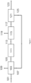
- a refinery has an SMR-based Hydrogen plant producing ⁇ 80kNm3/hr hydrogen.
- the existing hydrogen plant currently utilises 20,984 kgs/hr (1164.5 kgmols/hr) natural gas as feedstock and 3,466 kgs/hr (192.3 kgmols/hr) as fuel to the SMR (additional to PSA tail-gas fuel).
- This arrangement is shown in Figure 1 .
- the total energy input is -316MW LHV.
- Carbon dioxide is emitted to the atmosphere from the hydrogen plant at a rate of 64.7 tes/hr.
- the baseline Carbon intensity of the existing hydrogen plant with natural gas feed and fuel (scope 1 emissions) is therefore 9.06kgs COz/kg H 2 .
- the SMR-based hydrogen plant shown in Figure 1 is to be integrated with a renewable diesel (RND) hydrotreated processing a mix of vegetable oils, tallow and waste cooking oil to make 600,000 tes/yr RND (on stream factor 0.9)
- RND renewable diesel
- the approximate performance metrics of the new RND hydrotreater are as follows:
- FIG. 2 shows a block schematic of the new hydrotreater with the existing hydrogen plant.
- the hydrogen plant supplies hydrogen make-up (231) to the RNG hydrotreater, while off-gas is used on the existing hydrogen plant (242) , displacing all the natural gas fuel to the SMR (and leaving some off-gas fuel for use elsewhere on the refinery).
- Table 1 gives the stream flows and conditions.
- the emission of CO 2 from the hydrogen plant is 65.3 tes/hr of which -17% is biogenic, ie emissions of fossil-based COz is ⁇ 54 tes/hr. Compared to the hydrogen plant before the change this is a small reduction of 10.7 tes/hr (-17%).
- the Carbon intensity of the hydrogen plant (scope 1 emissions) is therefore 7.58kgs COz/kg H 2 (a reduction of ⁇ 1.5kgs COz/kg Hz over the base-line).
- the reduction of the carbon footprint of the renewable diesel product is ⁇ 0.04 x 1.5 - 0.06kgs COz/kg diesel or - 1g COz/MJ LHV.
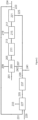
- FIG 3 shows a block schematic of the new hydrotreater and the hydrogen plant revamped with a tail-gas treatment Unit (TTU).
- TTU tail-gas treatment Unit
- the tail-gas feed is passed through a CO2 absorber to capture the CO2 content before being fed to the TTU autothermal reformer.
- the off-gas continues to be used as fuel in the Hydrogen plant SMR with the rest of the fuel being Hz product from the TTU.
- the SMR hydrogen plant supplies hydrogen make-up to the RNG hydrotreater.
- Table 2 gives the stream flows and conditions.
- the Carbon intensity of the hydrogen plant (scope 1 emissions) is therefore 0.57kgs COz/kg H 2 (a reduction of ⁇ 8.5kgs COz/kg Hz over the base-line).
- the reduction of the carbon footprint of the renewable diesel product is ⁇ 0.04 x 8.5 - 0.34kgs COz/kg diesel or - 8g COz/MJ LHV.
- FIG. 4 shows an example of a conversion of the existing SMR Hydrogen plant with a TTU and integration according to the invention with the RND hydrotreater. This example is configured for minimum natural gas input and maximum reduction of Hz product carbon intensity.
- the flows are as per Example 2 except that:
- Table 3 details key flows and conditions.
- the emission of COz from the revamped plant is -1.0 tes/hr of which 40% is biogenic, ie emissions of fossil-based COz is ⁇ 0.6 tes/hr. Compared to the hydrogen plant before its revamp this is a reduction of ⁇ 64.2 tes/hr (99%). There is also biogenic carbon capture of ⁇ 15.9 tes/hr
- the Carbon intensity of the hydrogen plant (scope 1 emissions) is therefore ⁇ -2.2kgs COz/kg H 2 (a reduction of ⁇ 11.3kgs COz/kg H 2 over the base-line).
- the reduction of the carbon footprint of the renewable diesel product is -0.04 x 11.3 - 0.45kgs COz/kg diesel or - 10g COz/MJ LHV
- Example 4 ( Figure 5 ) has a similar configuration to Example 3 ( Figure 4 ) Except that the TTU capacity is increased by feeding natural gas to it (as well as tail-gas and off-gas) in order to restore the export hydrogen capacity (net of hydrogen feed to the RND hydrotreater) to 80kNm3/hr.
- H 2 product from the TTU solely supplies the SMR reformer fuel duty.
- Both the tail-gas feed and off-gas feed are passed through absorbers to capture their COz content before being fed together with natural gas to the TTU autothermal reformer.
- Table 4 details key flows and conditions: It can be seen from the table that the net hydrogen export (streams 567+524) is ⁇ 80kNm3/hr, after providing a flow to the hydrotreater of ⁇ 33.8kNm3/hr.
- the total produced hydrogen from the revamped hydrogen plant is 113.6kNm3/hr, about 142% of the pre-retrofit rate.
- the emission of COz from the revamped plant is ⁇ 1.3 tes/hr of which 20% is biogenic, ie emissions of fossil-based COz is -1.1 tes/hr. Compared to the hydrogen plant before its revamp this is a reduction of -63.6 tes/hr (98.3%). There is also biogenic carbon capture of ⁇ 15.9 tes/hr
- the Carbon intensity of the hydrogen plant (scope 1 emissions) is therefore ⁇ -1.5kgs COz/kg H 2 (a reduction of ⁇ 10.6kgs COz/kg H 2 over the base-line).
- the reduction of the carbon footprint of the renewable diesel product is -0.04 x 10.6 - 0.42kgs COz/kg diesel or - 10g COz/MJ LHV.
- Example 5 The arrangement of Example 4 ( Figure 5 ) produces two hydrogen export streams; one of high purity (steam 524) and one of fuel quality (stream 567).
- Example 5 has a similar configuration to Example 4 except that the fuel quality stream is compressed and routed to the PSA unit on the existing Hydrogen plant, so that the full 80kNm3/hr hydrogen export from the PSA (net of feed to RND hydrotreater) is of 99.9% quality.
- Table 5 details key flows and conditions.
- the total produced hydrogen from the revamped hydrogen plant is 113.6kNm3/hr, about 142% of the pre-retrofit rate.
- the emission of COz from the revamped plant is -1.3 tes/hr of which 20% is biogenic, ie emissions of fossil-based COz is -1.1 tes/hr. Compared to the hydrogen plant before its revamp this is a reduction of -63.6 tes/hr (98.3%). There is also biogenic carbon capture of ⁇ 15.9 tes/hr
- the Carbon intensity of the hydrogen plant (scope 1 emissions) is therefore ⁇ -1.5kgs COz/kg H 2 (a reduction of ⁇ 10.6kgs COz/kg H 2 over the base-line).
- the reduction of the carbon footprint of the renewable diesel product is -0.04 x 10.6 - 0.42kgs COz/kg diesel or - 10g COz/MJ LHV. Table 1.
Landscapes
- Chemical & Material Sciences (AREA)
- Chemical Kinetics & Catalysis (AREA)
- Organic Chemistry (AREA)
- Engineering & Computer Science (AREA)
- Combustion & Propulsion (AREA)
- Inorganic Chemistry (AREA)
- Health & Medical Sciences (AREA)
- General Health & Medical Sciences (AREA)
- Oil, Petroleum & Natural Gas (AREA)
- General Chemical & Material Sciences (AREA)
- Hydrogen, Water And Hydrids (AREA)
Priority Applications (2)
| Application Number | Priority Date | Filing Date | Title |
|---|---|---|---|
| EP23169857.2A EP4455076A1 (de) | 2023-04-25 | 2023-04-25 | Entkarbonisierung einer wasserstoffbehandlungsanlage |
| PCT/GB2024/051068 WO2024224062A1 (en) | 2023-04-25 | 2024-04-24 | Decarbonisation of a hydrotreatment plant |
Applications Claiming Priority (1)
| Application Number | Priority Date | Filing Date | Title |
|---|---|---|---|
| EP23169857.2A EP4455076A1 (de) | 2023-04-25 | 2023-04-25 | Entkarbonisierung einer wasserstoffbehandlungsanlage |
Publications (1)
| Publication Number | Publication Date |
|---|---|
| EP4455076A1 true EP4455076A1 (de) | 2024-10-30 |
Family
ID=86226494
Family Applications (1)
| Application Number | Title | Priority Date | Filing Date |
|---|---|---|---|
| EP23169857.2A Pending EP4455076A1 (de) | 2023-04-25 | 2023-04-25 | Entkarbonisierung einer wasserstoffbehandlungsanlage |
Country Status (2)
| Country | Link |
|---|---|
| EP (1) | EP4455076A1 (de) |
| WO (1) | WO2024224062A1 (de) |
Citations (9)
| Publication number | Priority date | Publication date | Assignee | Title |
|---|---|---|---|---|
| GB1578270A (en) | 1977-04-04 | 1980-11-05 | Pullman Inc | Heat exchange apparatus |
| US4910228A (en) | 1988-02-18 | 1990-03-20 | Imperial Chemical Industries Plc | Methanol |
| WO1997005947A1 (en) | 1995-08-07 | 1997-02-20 | Imperial Chemical Industries Plc | Heat exchange apparatus and process |
| US20090298957A1 (en) * | 2004-11-16 | 2009-12-03 | Pierre-Robert Gauthier | Method and installation for combined production of hydrogen and carbon dioxide |
| WO2009151690A2 (en) | 2008-03-17 | 2009-12-17 | Uop Llc | Production of aviation fuel from renewable feedstocks |
| CN101285004B (zh) * | 2007-04-11 | 2010-12-15 | 中国科学院工程热物理研究所 | 一种多功能能源装置 |
| CN107557075B (zh) * | 2017-10-23 | 2019-11-08 | 武汉凯迪工程技术研究总院有限公司 | 生物质间接液化制合成油工艺及其系统 |
| WO2021180805A1 (en) | 2020-03-13 | 2021-09-16 | Haldor Topsøe A/S | Process and plant for producing hydrocarbons with reduced co2-footprint and improved hydrogen integration |
| WO2022003312A1 (en) | 2020-06-30 | 2022-01-06 | Johnson Matthey Public Limited Company | Process for producing hydrogen |
Family Cites Families (1)
| Publication number | Priority date | Publication date | Assignee | Title |
|---|---|---|---|---|
| US11772966B2 (en) | 2021-03-29 | 2023-10-03 | Uop Llc | Integrated hydrogen production and bio-renewable conversion process |
-
2023
- 2023-04-25 EP EP23169857.2A patent/EP4455076A1/de active Pending
-
2024
- 2024-04-24 WO PCT/GB2024/051068 patent/WO2024224062A1/en active Pending
Patent Citations (9)
| Publication number | Priority date | Publication date | Assignee | Title |
|---|---|---|---|---|
| GB1578270A (en) | 1977-04-04 | 1980-11-05 | Pullman Inc | Heat exchange apparatus |
| US4910228A (en) | 1988-02-18 | 1990-03-20 | Imperial Chemical Industries Plc | Methanol |
| WO1997005947A1 (en) | 1995-08-07 | 1997-02-20 | Imperial Chemical Industries Plc | Heat exchange apparatus and process |
| US20090298957A1 (en) * | 2004-11-16 | 2009-12-03 | Pierre-Robert Gauthier | Method and installation for combined production of hydrogen and carbon dioxide |
| CN101285004B (zh) * | 2007-04-11 | 2010-12-15 | 中国科学院工程热物理研究所 | 一种多功能能源装置 |
| WO2009151690A2 (en) | 2008-03-17 | 2009-12-17 | Uop Llc | Production of aviation fuel from renewable feedstocks |
| CN107557075B (zh) * | 2017-10-23 | 2019-11-08 | 武汉凯迪工程技术研究总院有限公司 | 生物质间接液化制合成油工艺及其系统 |
| WO2021180805A1 (en) | 2020-03-13 | 2021-09-16 | Haldor Topsøe A/S | Process and plant for producing hydrocarbons with reduced co2-footprint and improved hydrogen integration |
| WO2022003312A1 (en) | 2020-06-30 | 2022-01-06 | Johnson Matthey Public Limited Company | Process for producing hydrogen |
Non-Patent Citations (1)
| Title |
|---|
| A. GRUIA: "Handbook of Petroleum Processing", pages: 321 - 354 |
Also Published As
| Publication number | Publication date |
|---|---|
| WO2024224062A1 (en) | 2024-10-31 |
Similar Documents
| Publication | Publication Date | Title |
|---|---|---|
| RU2516527C2 (ru) | Системы и способы производства сверхчистого водорода при высоком давлении | |
| US8591769B2 (en) | Hydrogen production with reduced carbon dioxide generation and complete capture | |
| US9365466B2 (en) | Method and system for producing a liquid hydrocarbon product from a Fischer-Tropsch process using a synthesis gas produced from an oxygen transport membrane based reforming reactor | |
| KR20230029615A (ko) | 수소 생성 방법 | |
| US8580153B2 (en) | Hydrogen production with reduced carbon dioxide generation and complete capture | |
| RU2437830C2 (ru) | Способ получения синтез-газа | |
| EP4380893B1 (de) | Verfahren zur mit co2-abscheidung gekoppelten wasserstoffherstellung | |
| CN105820036B (zh) | 使用部分氧化生产甲醇的方法和系统 | |
| KR20070050071A (ko) | 수소 및/또는 일산화탄소의 제조방법 | |
| US20230294985A1 (en) | Low carbon hydrogen fuel | |
| EP2944606A1 (de) | Verfahren zur Erzeugung von Wasserstoff aus einem Fischer-Tropsch-Abgas | |
| JP2020508951A (ja) | 燃焼のための酸素および燃料の予熱と組み合わせてプレ−リフォーマーを使用する強化された廃熱回収 | |
| US9216396B2 (en) | Non-catalytic recuperative reformer | |
| EP4455076A1 (de) | Entkarbonisierung einer wasserstoffbehandlungsanlage | |
| GB2625645A (en) | Process for producing hydrogen | |
| KR20250128296A (ko) | 수소를 생성하기 위한 공정 | |
| CN120826385A (zh) | 用于合成甲醇的方法 | |
| JP7680538B2 (ja) | 水蒸気改質プラントの窒素酸化物排出を最小化するための方法及びその水蒸気改質プラント | |
| EP4530251A1 (de) | Entkarbonisierung einer chemischen anlage | |
| US20250034458A1 (en) | Integration of steam cracker and blue ammonia units to reduce co2 emission | |
| EA046288B1 (ru) | Низкоуглеродное водородное топливо | |
| TW202502646A (zh) | 用於以降低的co排放從烴生產氫氣的工廠及程序 | |
| KR20250155008A (ko) | 블루 암모니아의 생산 방법 | |
| GB2634156A (en) | Process for synthesising methanol | |
| AU2023202926A1 (en) | Hydrogen production process and plant |
Legal Events
| Date | Code | Title | Description |
|---|---|---|---|
| PUAI | Public reference made under article 153(3) epc to a published international application that has entered the european phase |
Free format text: ORIGINAL CODE: 0009012 |
|
| STAA | Information on the status of an ep patent application or granted ep patent |
Free format text: STATUS: THE APPLICATION HAS BEEN PUBLISHED |
|
| AK | Designated contracting states |
Kind code of ref document: A1 Designated state(s): AL AT BE BG CH CY CZ DE DK EE ES FI FR GB GR HR HU IE IS IT LI LT LU LV MC ME MK MT NL NO PL PT RO RS SE SI SK SM TR |
|
| RAP3 | Party data changed (applicant data changed or rights of an application transferred) |
Owner name: JOHNSON MATTHEY PUBLIC LIMITED COMPANY |
|
| STAA | Information on the status of an ep patent application or granted ep patent |
Free format text: STATUS: REQUEST FOR EXAMINATION WAS MADE |
|
| 17P | Request for examination filed |
Effective date: 20250425 |
|
| GRAP | Despatch of communication of intention to grant a patent |
Free format text: ORIGINAL CODE: EPIDOSNIGR1 |
|
| STAA | Information on the status of an ep patent application or granted ep patent |
Free format text: STATUS: GRANT OF PATENT IS INTENDED |
|
| INTG | Intention to grant announced |
Effective date: 20250908 |
|
| RAP1 | Party data changed (applicant data changed or rights of an application transferred) |
Owner name: JOHNSON MATTHEY DAVY TECHNOLOGIES LIMITED |