EP4454916A1 - Electric work vehicle - Google Patents
Electric work vehicle Download PDFInfo
- Publication number
- EP4454916A1 EP4454916A1 EP22910655.4A EP22910655A EP4454916A1 EP 4454916 A1 EP4454916 A1 EP 4454916A1 EP 22910655 A EP22910655 A EP 22910655A EP 4454916 A1 EP4454916 A1 EP 4454916A1
- Authority
- EP
- European Patent Office
- Prior art keywords
- case lid
- case
- work vehicle
- case body
- peripheral wall
- Prior art date
- Legal status (The legal status is an assumption and is not a legal conclusion. Google has not performed a legal analysis and makes no representation as to the accuracy of the status listed.)
- Pending
Links
Images






Classifications
-
- H—ELECTRICITY
- H02—GENERATION; CONVERSION OR DISTRIBUTION OF ELECTRIC POWER
- H02K—DYNAMO-ELECTRIC MACHINES
- H02K11/00—Structural association of dynamo-electric machines with electric components or with devices for shielding, monitoring or protection
- H02K11/30—Structural association with control circuits or drive circuits
- H02K11/33—Drive circuits, e.g. power electronics
-
- A—HUMAN NECESSITIES
- A01—AGRICULTURE; FORESTRY; ANIMAL HUSBANDRY; HUNTING; TRAPPING; FISHING
- A01D—HARVESTING; MOWING
- A01D34/00—Mowers; Mowing apparatus of harvesters
- A01D34/01—Mowers; Mowing apparatus of harvesters characterised by features relating to the type of cutting apparatus
- A01D34/412—Mowers; Mowing apparatus of harvesters characterised by features relating to the type of cutting apparatus having rotating cutters
- A01D34/63—Mowers; Mowing apparatus of harvesters characterised by features relating to the type of cutting apparatus having rotating cutters having cutters rotating about a vertical axis
- A01D34/81—Casings; Housings
-
- B—PERFORMING OPERATIONS; TRANSPORTING
- B60—VEHICLES IN GENERAL
- B60K—ARRANGEMENT OR MOUNTING OF PROPULSION UNITS OR OF TRANSMISSIONS IN VEHICLES; ARRANGEMENT OR MOUNTING OF PLURAL DIVERSE PRIME-MOVERS IN VEHICLES; AUXILIARY DRIVES FOR VEHICLES; INSTRUMENTATION OR DASHBOARDS FOR VEHICLES; ARRANGEMENTS IN CONNECTION WITH COOLING, AIR INTAKE, GAS EXHAUST OR FUEL SUPPLY OF PROPULSION UNITS IN VEHICLES
- B60K1/00—Arrangement or mounting of electrical propulsion units
- B60K1/04—Arrangement or mounting of electrical propulsion units of the electric storage means for propulsion
-
- B—PERFORMING OPERATIONS; TRANSPORTING
- B60—VEHICLES IN GENERAL
- B60L—PROPULSION OF ELECTRICALLY-PROPELLED VEHICLES; SUPPLYING ELECTRIC POWER FOR AUXILIARY EQUIPMENT OF ELECTRICALLY-PROPELLED VEHICLES; ELECTRODYNAMIC BRAKE SYSTEMS FOR VEHICLES IN GENERAL; MAGNETIC SUSPENSION OR LEVITATION FOR VEHICLES; MONITORING OPERATING VARIABLES OF ELECTRICALLY-PROPELLED VEHICLES; ELECTRIC SAFETY DEVICES FOR ELECTRICALLY-PROPELLED VEHICLES
- B60L15/00—Methods, circuits, or devices for controlling the traction-motor speed of electrically-propelled vehicles
- B60L15/007—Physical arrangements or structures of drive train converters specially adapted for the propulsion motors of electric vehicles
-
- B—PERFORMING OPERATIONS; TRANSPORTING
- B60—VEHICLES IN GENERAL
- B60L—PROPULSION OF ELECTRICALLY-PROPELLED VEHICLES; SUPPLYING ELECTRIC POWER FOR AUXILIARY EQUIPMENT OF ELECTRICALLY-PROPELLED VEHICLES; ELECTRODYNAMIC BRAKE SYSTEMS FOR VEHICLES IN GENERAL; MAGNETIC SUSPENSION OR LEVITATION FOR VEHICLES; MONITORING OPERATING VARIABLES OF ELECTRICALLY-PROPELLED VEHICLES; ELECTRIC SAFETY DEVICES FOR ELECTRICALLY-PROPELLED VEHICLES
- B60L50/00—Electric propulsion with power supplied within the vehicle
- B60L50/50—Electric propulsion with power supplied within the vehicle using propulsion power supplied by batteries or fuel cells
- B60L50/60—Electric propulsion with power supplied within the vehicle using propulsion power supplied by batteries or fuel cells using power supplied by batteries
-
- H—ELECTRICITY
- H02—GENERATION; CONVERSION OR DISTRIBUTION OF ELECTRIC POWER
- H02G—INSTALLATION OF ELECTRIC CABLES OR LINES, OR OF COMBINED OPTICAL AND ELECTRIC CABLES OR LINES
- H02G3/00—Installations of electric cables or lines or protective tubing therefor in or on buildings, equivalent structures or vehicles
- H02G3/02—Details
- H02G3/08—Distribution boxes; Connection or junction boxes
- H02G3/14—Fastening of cover or lid to box
-
- H—ELECTRICITY
- H02—GENERATION; CONVERSION OR DISTRIBUTION OF ELECTRIC POWER
- H02G—INSTALLATION OF ELECTRIC CABLES OR LINES, OR OF COMBINED OPTICAL AND ELECTRIC CABLES OR LINES
- H02G3/00—Installations of electric cables or lines or protective tubing therefor in or on buildings, equivalent structures or vehicles
- H02G3/02—Details
- H02G3/08—Distribution boxes; Connection or junction boxes
- H02G3/16—Distribution boxes; Connection or junction boxes structurally associated with support for line-connecting terminals within the box
-
- H—ELECTRICITY
- H05—ELECTRIC TECHNIQUES NOT OTHERWISE PROVIDED FOR
- H05K—PRINTED CIRCUITS; CASINGS OR CONSTRUCTIONAL DETAILS OF ELECTRIC APPARATUS; MANUFACTURE OF ASSEMBLAGES OF ELECTRICAL COMPONENTS
- H05K7/00—Constructional details common to different types of electric apparatus
- H05K7/14—Mounting supporting structure in casing or on frame or rack
- H05K7/1422—Printed circuit boards receptacles, e.g. stacked structures, electronic circuit modules or box like frames
- H05K7/1427—Housings
- H05K7/1432—Housings specially adapted for power drive units or power converters
-
- A—HUMAN NECESSITIES
- A01—AGRICULTURE; FORESTRY; ANIMAL HUSBANDRY; HUNTING; TRAPPING; FISHING
- A01D—HARVESTING; MOWING
- A01D2101/00—Lawn-mowers
-
- A—HUMAN NECESSITIES
- A01—AGRICULTURE; FORESTRY; ANIMAL HUSBANDRY; HUNTING; TRAPPING; FISHING
- A01D—HARVESTING; MOWING
- A01D69/00—Driving mechanisms or parts thereof for harvesters or mowers
- A01D69/02—Driving mechanisms or parts thereof for harvesters or mowers electric
-
- B—PERFORMING OPERATIONS; TRANSPORTING
- B60—VEHICLES IN GENERAL
- B60L—PROPULSION OF ELECTRICALLY-PROPELLED VEHICLES; SUPPLYING ELECTRIC POWER FOR AUXILIARY EQUIPMENT OF ELECTRICALLY-PROPELLED VEHICLES; ELECTRODYNAMIC BRAKE SYSTEMS FOR VEHICLES IN GENERAL; MAGNETIC SUSPENSION OR LEVITATION FOR VEHICLES; MONITORING OPERATING VARIABLES OF ELECTRICALLY-PROPELLED VEHICLES; ELECTRIC SAFETY DEVICES FOR ELECTRICALLY-PROPELLED VEHICLES
- B60L2200/00—Type of vehicles
- B60L2200/40—Working vehicles
-
- B—PERFORMING OPERATIONS; TRANSPORTING
- B60—VEHICLES IN GENERAL
- B60L—PROPULSION OF ELECTRICALLY-PROPELLED VEHICLES; SUPPLYING ELECTRIC POWER FOR AUXILIARY EQUIPMENT OF ELECTRICALLY-PROPELLED VEHICLES; ELECTRODYNAMIC BRAKE SYSTEMS FOR VEHICLES IN GENERAL; MAGNETIC SUSPENSION OR LEVITATION FOR VEHICLES; MONITORING OPERATING VARIABLES OF ELECTRICALLY-PROPELLED VEHICLES; ELECTRIC SAFETY DEVICES FOR ELECTRICALLY-PROPELLED VEHICLES
- B60L2270/00—Problem solutions or means not otherwise provided for
- B60L2270/10—Emission reduction
- B60L2270/14—Emission reduction of noise
- B60L2270/145—Structure borne vibrations
Definitions
- the present invention relates to an electric work vehicle that includes a battery, a motor driven by electric power supplied from the battery, and a travel device driven by the motor.
- Patent Document 1 An electric work vehicle such as described above has already been disclosed in Patent Document 1, for example.
- This electric work vehicle (“tractor” in Patent Document 1) has an inverter device (“inverter” in Patent Document 1) interposed on the power supply path from the battery to the electric motor.
- Patent Document 1 JP 2021-953A
- the electric work vehicle having the structure shown in Patent Document 1 has a reasonably sturdily support structure in which a large inverter support portion that is supported by left and right body frames is integrally formed with a relatively sturdily battery support base for supporting a large battery. Attaching the inverter device to the inverter support portion serving a sturdy support structure allows transmission of shaking, vibration and the like to the inverter device to be suppressed as much as possible.
- the invention aims to reduce the effects of shaking, vibration and the like transmitted to an inverter device by providing the inverter device itself with a vibration resistance function.
- Patent Document 1 merely shows the inverter device as a box-shaped body, and the specific structure thereof is not disclosed.
- the inverter device When the inverter device has a structure that merely combines a box-shaped body and a lid body, with an inverter circuit housed in the box-shaped body being accessed for maintenance purposes by opening the lid body, the region of the case body where the case lid opens and closes is required to be firmly sealed, so as to reliably avoid ingress of dust, rainwater, and the like from outside through this region. Furthermore, measures are also needed to avoid degradation of the sealing properties due to deterioration of the seal over time, and there is room for improvement in terms of the risk of adding complexity to the structure and making the opening/closing operation more troublesome.
- the invention further aims to provide an electric work vehicle in which ingress of dust, rainwater, and the like through the region where an exterior case used as an inverter device opens and closes is readily reliably avoided with a simple structure.
- the rigidity of the exterior case housing the substrate provided with the inverter circuit is enhanced by forming a reinforcing rib on the outer surface of the peripheral wall portion of the case body and on the inner surface of the case lid. A reduction in shaking, vibration and the like transmitted to the inverter device can thereby be achieved.
- the reinforcing rib formed on the exterior case is advantageous in terms of being able to enhance the heat dissipation effect obtained through contact with the outside air, as a result of being formed of the outer surface of the peripheral wall portion of the case body.
- the reinforcing rib formed on the inner surface of the case lid helps strengthen the exterior case as a whole, while accumulation of dust is readily avoided and installation of the exterior case in the narrow space between the vehicle body frame and the battery installation base is facilitated, as a result of a reinforcing rib that protrudes upward not being provided on the upper surface of the case lid.
- the at least one reinforcing rib formed on the peripheral wall portion is at least one vertical rib extending in an up-down direction
- the at least one reinforcing rib formed on the inner surface of the case lid is at least one diagonal grid-shaped rib extending in a diagonal direction of the case lid.
- the at least one vertical rib does not protrude outside an outer peripheral edge of an upper end of the peripheral wall portion, and the peripheral wall portion includes an outer wall surface between the vertical ribs positioned adjacent to each other that is formed as a recessed wall surface recessed to approach closer to an inner wall surface of the case body than is a place where the vertical ribs are formed.
- the high vertical strength of the exterior case is maintained as a result of the vertical ribs, while securing a large surface area of the peripheral wall portion as a result of the outer wall surface located between the vertical ribs being formed as a recessed wall surface that is recessed to approach the inner wall surface of the case body. Heat is thereby readily efficiently dissipated, and weight reduction is readily achieved at the same time.
- the at least one vertical rib overlaps, in side view, with a screw hole formed in the peripheral wall portion in order to fasten the case lid to the case body.
- the at least one diagonal grid-shaped rib extends in a direction joining coupling holes for bolt insertion formed in a rectangular peripheral portion of the case lid.
- the diagonal grid-shaped rib on the case lid extending in a direction that joins coupling holes for bolt insertion, the diagonal grid-shaped rib acts like a brace while the case body and the case lid are fastened together, and the strength of the exterior case as a whole is readily enhanced.
- the inner surface of the case lid includes a region in which part of the at least one diagonal grid-shaped rib protruding into the space does not exist, and between the case lid and a component attached to the case body at a place facing the region is formed a space for securing an insulation distance.
- the exterior case is constituted by a conductive member
- the provision of a region in which part of the diagonal grid-shaped rib protruding into the inner space of the case does not exist enables a space for securing an insulation distance to be formed between that region and a component facing that region.
- the bottom plate portion is provided, on a lower surface thereof, with a grid-shaped rib extending in the front-back direction and the left-right direction parallel to extension directions of the peripheral wall portion in plan view.
- a cushioning material for vibration isolation preferably between an upper end surface of the peripheral wall portion of the case body and an inner surface of a peripheral portion of the case lid is sandwiched a cushioning material for vibration isolation.
- the substrate stopping portion fixedly supports, on an upper surface of the bottom plate portion, a peripheral portion and a vicinity of a central portion of the substrate provided with the inverter circuit.
- the substrate itself is less likely to flex, and shaking, vibration and the like are more readily suppressed.
- the substrate stopping portion includes a plurality of protruding pedestals for receiving and fastening the substrate, and the protruding pedestals positioned adjacent to each other are connected by a coupling rib.
- the protruding pedestals of the substrate stopping portion are connected to each other by a coupling rib, and shaking, vibration and the like of the protruding pedestals are readily suppressed.
- an electric work vehicle of the invention is characterized by including:
- a lip portion located on the outer side of the upper end portion of the case body and lower than the upper end portion of the case body is formed on a lower peripheral portion of the case lid configured to open and close the open upper end of the case body. Accordingly, the open upper end of the case body can be closed, with the outer side of the contact point between the case body and the case lid surrounded by the lip portion, compared to a structure in which the case body and the case lid are merely coupled together by coupling bolts.
- the upper end of the case body and the case lid contact each other at a point higher than the lower peripheral portion of the case lid, and the contact point has a gasket interposed therein.
- a gasket is provided at the contact point between the upper end of the case body and the case lid, at a higher position than the lower peripheral portion of the case lid, which portion is located on the outer side the upper end portion of the case body, and thus the possibility of this gasket coming into direct contact with dust, rainwater, and the like from outside is reduced. Ingress of dust, rainwater, and the like inside of the exterior case is thereby more readily prevented.
- the case lid is provided, on part of an outer peripheral portion thereof, with a striking protrusion protruding outward.
- a striking protrusion that partially protrudes outward is formed on an outer peripheral portion of the case lid, and thus, if the case lid is difficult to open due to sticking to the upper end of the case body as a result of not been opened and closed for an extended period of time, this situation is readily resolved by striking the striking protrusion from outside.
- the striking protrusion protrudes horizontally outward from between bolt holes formed on a periphery of the outer peripheral portion of the case lid.
- the striking protrusion protrudes horizontally outward from between the bolt holes formed on the periphery of the outer peripheral portion of the case lid, and thus the force generated by the striking action works effectively on the place where the degree of adhesion is high due to being firmly tightened by the coupling bolts, and the situation where the case lid is adhered to the case body is more readily resolved.
- the striking protrusion is provided with a reinforcing rib extending in a protruding direction of the striking protrusion.
- the striking protrusion can be reinforced with a reinforcing rib, and the force generated by the striking action is readily accurately applied to the adhesion point between the case lid and the case body.
- the tractor includes left and right front wheels 10, left and right rear wheels 11, and a cover member 12.
- the tractor includes a body frame 2 and a driving section 3.
- the body frame 2 is supported by the left and right front wheels 10 and the left and right rear wheels 11.
- the cover member 12 is disposed in a front body portion.
- the driving section 3 is provided behind the cover member 12. In other words, the cover member 12 is disposed in front of the driving section 3.
- the driving section 3 has a protective frame 30, a driver's seat 31, and a steering wheel 32. An operator can sit in the driver's seat 31. The operator can thereby ride in the driving section 3. The left and right front wheels 10 are steered by operating the steering wheel 32. The operator is able to perform various driving operations in the driving section 3.
- the tractor is provided with a travel battery 4. Also, the cover member 12 is pivotable about an opening-closing axis Q extending the left-right direction of the body. The cover member 12 is thereby openable and closable. While the cover member 12 is closed, the travel battery 4 is covered by the cover member 12.
- the tractor includes an inverter 14 (corresponds to inverter device) and a motor M.
- the travel battery 4 supplies electric power to the inverter 14.
- the inverter 14 converts DC power from the travel battery 4 into AC power and supplies the AC power to the motor M.
- the motor M is then driven by the AC power supplied from the inverter 14.
- the tractor includes a hydrostatic continuously variable transmission (CVT) 15 and a transmission 16.
- CVT continuously variable transmission
- the hydrostatic CVT 15 has a hydraulic pump 15a and a hydraulic motor 15b.
- the hydraulic pump 15a is driven by rotational power from the motor M. Rotational power is output from the hydraulic motor 15b, in response to the hydraulic pump 15a being driven. Note that, in the hydrostatic CVT 15, rotational power is varied between the hydraulic pump 15a and the hydraulic motor 15b. Also, the transmission ratio of the hydrostatic CVT 15 can be changed continuously.
- the rotational power output from the hydraulic motor 15b is transmitted to the transmission 16.
- the rotational power transmitted to the transmission 16 is varied by a geared transmission mechanism of the transmission 16 and distributed to the left and right front wheels 10 and the left and right rear wheels 11.
- the left and right front wheels 10 and the left and right rear wheels 11 are thereby driven.
- the tractor includes a mid power takeoff (PTO) shaft 17 and a rear power takeoff (PTO) shaft 18.
- the rotational power output from the motor M is distributed to the hydraulic pump 15a, the mid PTO shaft 17, and the rear PTO shaft 18.
- the mid PTO shaft 17 and the rear PTO shaft 18 thereby rotate.
- a work device is connected to the mid PTO shaft 17 (or the rear PTO shaft 18), the work device will be driven by the rotational power of the mid PTO shaft 17 (or the rear PTO shaft 18).
- a mowing device 19 is connected to the mid PTO shaft 17. The mowing device 19 is driven by the rotational power of the mid PTO shaft 17.
- the body frame 2 includes left and right front-back frames 2A and a lateral frame 2B.
- the left and right front-back frames 2A extend in the front-back direction of the body, and the lateral frame 2B joins the left and right front-back frames 2A to each other.
- the lateral frame 2B is coupled to lower portions of the left and right front-back frames 2A, and extends in the front-back direction in a plan view from the region where the front end portion of the inverter 14 is located to the region where the front end portion of the motor M is located.
- the lateral frame 2B is coupled to an axle unit 10F extending in the left-right direction of the body of the tractor (corresponds to electric work vehicle).
- the front wheels 10 are rotationally supported by left and right end portions of the axle unit 10F.
- the transmission 16 and the axle unit 10F are coupled to a propeller shaft 13 extending in the front-back direction of the body below the lateral frame 2B.
- the inverter 14 and the motor M are disposed adjacent to each other in the front-back direction. In other words, the inverter 14 and the motor M are aligned with each other in the front-back direction of the body.
- the motor M and the inverter 14 are supported by the left and right front-back frames 2A in such a manner as to be aligned with each other in the front-back direction of the body between the left and right front-back frames 2A.
- the inverter 14 is in front of the motor M.
- the inverter 14 and the motor M are connected by a power supply cable 21.
- the power supply cable 21 is detachably connected at one end portion 21A to an output connector 14C of the inverter 14, and is detachably connected at an opposite end 21B to a power receiving connector 22 of the motor M.
- the output connector 14C is located in a region of the exterior case 5 on the opposite side to the motor M.
- the power supply cable 21 is located above the lateral frame 2B and is housed between the left and right front-back frames 2A. That is, the power supply cable 21 extends in the front-back direction through the space surrounded by the left and right front-back frames 2A, the lateral frame 2B, and a bottom plate portion 50 of the exterior case 5. The possibility of the output connector 14C and the power supply cable 21 coming into contact with foreign objects is thereby avoided, and the possibility of the output connector 14C and the power supply cable 21 becoming detached in response to coming into contact with foreign objects can be reduced.
- the travel battery 4 is supported by the left and right front-back frames 2A in such a manner as to be located directly above the inverter 14. Specifically, as shown in FIGS. 4 to 6 , on upper end portions of the left and right front-back frames 2A are respectively formed left and right support surface portions 23. On the left and right support surface portions 23 is placed a battery installation base 24, and the travel battery 4 is placed on the battery installation base 24.
- the left and right support surface portions 23 extend in the lateral direction of the body at upper end portions of the left and right front-back frames 2A.
- triangular ribs 27 extend between the support surface portions 23 and the front-back frames 2A to prevent the left and right support surface portions 23 from sagging with respect to the left and right front-back frames 2A.
- the triangular ribs 27 are welded, at contact sides thereof, to the front-back frames 2A and the support surface portions 23, and the support surface portions 23 are thereby integrally formed with the front-back frames 2A via the triangular ribs 27, and constitute part of the body frame 2.
- the bottom portion of the inverter 14 is coupled to the support surface portions 23 by attachment bolts 28. The inverter 14 is thus removably supported by the body frame 2.
- the battery installation base 24 is bolted to the left and right support surface portions 23. As shown in FIGS. 4 to 6 , the battery installation base 24 is formed by welding together attachment plates 24C that respectively partially overlap with the left and right support surface portions 23, C-shaped steel vertical frames 24A that extends in the up-down direction on the attachment plates 24C, left and right steel angles 24B that extend in the front-back direction of the body at upper end portions of the left and right vertical frames 24A, and a lateral steel angle that joins the left and right steel angles 24B extending in the front-back direction of the body.
- the attachment plates 24C have bolt insertion holes 24Ca for bolting the attachment plates 24C to the support surface portions 23 formed therein, and the attachment plates 24C and the support surface portions 23 can be fixedly coupled together via coupling bolts 26.
- the battery installation base 24 is gate shaped as viewed in the front-back direction of the body. The battery installation base 24 covers the inverter 14 from above and from the left and right sides.
- the inverter 14 of the present embodiment will now be described with reference to FIGS. 4 to 15 .
- the inverter 14 converts direct current from the travel battery 4 into alternating current and supplies the alternating current to the motor M.
- the inverter 14 houses a substrate 60 on which an inverter circuit 6 is provided, a capacitor 61, and the like in the exterior case 5 which includes a case body 5A and a case lid 5B.
- the inverter circuit 6 is a circuit body that converts direct current from the travel battery 4 into alternating current, and is provided with an inverter module constituted by an insulated gate bipolar transistor (IGBT), for example, and by an inverter control module that communicates with a higher-order electronic control unit (ECU) and controls the inverter module.
- the capacitor 61 holds the supply voltage for the inverter module at a constant voltage.
- the substrate 60 includes a first substrate 60A on which the inverter module is provided and a second substrate 60B on which the inverter control module is provided.
- a first substrate stopping portion 51 for fixing the first substrate 60A As shown in FIGS. 12 and 13 , on the bottom plate portion 50 of the case body 5A is provided a first substrate stopping portion 51 for fixing the first substrate 60A.
- a second substrate stopping portion 52 is provided for fixing the second substrate 60B, which is a different substrate 60 from the first substrate 60A, at a position overlapping the first substrate 60A from above.
- the first substrate stopping portion 51 includes protruding pedestals 53 for receiving a peripheral portion and a central portion of the first substrate 60A and fixing the peripheral and central portions of the first substrate 60A to the bottom plate portion 50.
- the peripheral and central portions of the first substrate 60A are fixed to the bottom plate portion 50, using screw holes provided in the protruding pedestals 53 and set screws, with the protruding pedestals 53 positioned to face the peripheral and central portions of the first substrate 60A.
- the second substrate stopping portion 52 includes an attachment plate 62 capable of supporting a peripheral portion and a central portion of the second substrate 60B, and protruding pedestals 53 for receiving a peripheral portion of the attachment plate 62 and fixing the peripheral portion of the attachment plate 62 to the bottom plate portion 50.
- the peripheral and central portions of the second substrate 60B supported by the attachment plate 62 are fixed to the bottom plate portion 50, as a result of the attachment plate 62 being fixed to the bottom plate portion 50, using screw holes provided in the protruding pedestals 53 and set screws, with the protruding pedestals 53 positioned to face the peripheral portion of the attachment plate 62, while the peripheral and central portions of the second substrate 60B are supported by the attachment plate 62.
- some of the adjacently positioned protruding pedestals 53 are connected to each other by coupling ribs 54.
- the protruding pedestals 53 having a high protruding height upward from the bottom plate portion 50 and are for fixing the attachment plate 62 to the bottom plate portion 50 are connected to each other and to the inner surface of the case body 5A described later by the coupling ribs 54. Shaking of the protruding pedestals 53 having a high protruding height from the bottom plate portion 50 is thereby readily effectively suppressed. As a result, transmission of shaking, vibration and the like to the attachment plate 62 and the second substrate 60B fixed to the attachment plate 62 are readily reduced.
- the travel battery 4 and the inverter 14 are electrically connected to each other by a power cable 20 (corresponds to input harness). Direct current flows through the power cable 20.
- the inverter 14 is provided with an input connector 14B (corresponds to input connection portion).
- the input connector 14B protrudes forward of a front portion of the exterior case 5 and is electrically connected to a connection port 20A of the power cable 20.
- the inverter 14 includes the input connector 14B electrically connected to the power cable 20, the inverter circuit 6 that converts direct current into alternating current, and the output connector 14C (output connection portion) electrically connected to the power supply cable 21 (corresponds to the output harness).
- the exterior case 5 is an aluminum die-cast product that includes the case body 5A having a rectangular box shape and the case lid 5B having a rectangular plate shape.
- the rectangular box-shaped case body 5A includes the bottom plate portion 50 and a peripheral wall portion 55, and the space surrounded by the bottom plate portion 50 and the peripheral wall portion 55 is open upward.
- the case lid 5B is couplable to and uncouplable from an upper end portion of the case body 5A, in such a manner that the opening in the case body 5A is openable and closable.
- the first substrate stopping portion 51 and the second substrate stopping portion 52 for fixing the substrate 60 are provided on the bottom plate portion 50 of the case body 5A.
- the inverter circuit 6 is housed in the exterior case 5 by closing the opening of the case body 5A with the case lid 5B, with the first substrate 60A and the second substrate 60B respectively attached to the first substrate stopping portion 51 and the second substrate stopping portion 52.
- grid-shaped reinforcing ribs 56 including vertical ribs 55a that extend in the up-down direction and lateral ribs 55b that extend in the horizontal direction.
- the reinforcing ribs 56 are formed in such a manner that the vertical ribs 55a and the lateral ribs 55b do not protrude outside the outer peripheral edge of the upper end of the peripheral wall portion 55.
- the outer wall surface between the adjacent vertical ribs 55a is formed as a recessed wall surface provided, at various places, with recessed portions 55c that are recessed to approach closer to the inner wall surface of the case body 5A than are places where the vertical ribs 55a are formed.
- the vertical ribs 55a and the lateral ribs 55b are not formed to protrude outward of the outer peripheral edge of the upper end of the peripheral wall portion 55, but, conversely, are the portions that remain as reinforcing ribs 56, as a result of the peripheral wall portion 55 being formed in such a manner that part of the outer wall surface thereof is recessed by providing the recessed portions 55c.
- screw holes 55d into which coupling bolts 57 for fastening the case lid 5B while the case lid 5B faces the opening in the case body 5A are screwable.
- the screw holes 55d are formed at positions that overlap with the vertical ribs 55a in side view.
- the recess depth of the recessed portions 55c corresponds to a distance d1 from the outer end to the inner end of the vertical ribs 55a.
- the far inner portion of the recessed portions 55c is formed to approach closer to the inner wall surface of the peripheral wall portion 55 than are the places where the coupling bolts 57 are provided.
- the grid-shaped reinforcing ribs 56 are formed not only on the left side surface shown in FIG. 8 and the rear surface shown in FIG. 9 , but are also similarly formed on the front surface shown in FIG. 5 and on the right side surface which is not shown.
- reinforcing ribs 56 including front-rear ribs 50a extending in the front-back direction and left-right ribs 50b extending in the left-right direction.
- attachment seats 50d for fixing the case body 5A to the support surface portions 23 of the front-back frames 2A.
- These attachment seats 50d are provided with attachment holes 50e for fixing via the attachment bolt 28.
- the front-rear ribs 50a and the left-right ribs 50b are also formed by providing upward-facing recessed portions 50c in the place surrounded by the front-rear ribs 50a and the left-right ribs 50b, rather than being formed to protrude lower than the lower surface of the attachment seat 50d provided at the lower end of the outer peripheral edge of the bottom plate portion 50.
- the recess depth of the upward-facing recessed portion 50c corresponds to a distance d2 from the lower end to the upper end of the front-rear ribs 50a and the left-right ribs 50b.
- the recessed portions 50c are formed to be shallower than the recessed portions 55c, by making this distance d2 shorter than the distance d1 (see FIG. 13 ) corresponding to the recess depth of the recessed portions 55c in the peripheral wall portion 55 described above.
- the peripheral wall portion 55 of the case body 5A includes a rear-facing wall portion 55R that faces the rearward side of the body and is provided with a breathing hole 7 for ventilation through which air inside the exterior case 5 can be exhausted.
- This breathing hole 7 is provided with a filter 70 to allow internal air to be exhausted following a rise in air pressure within the exterior case 5 due to factors such as heat generated by the inverter circuit 6, and to restrict ingress of dust, rainwater, and the like from outside.
- the exterior case 5 is installed on the front-back frames 2A so as to be allocated on the left and right of a vertical line CL that passes through a central position between the left and right front-back frames 2A in the left-right direction, that is, a central position in the left-right direction of the body.
- the vertical line CL intersects an axis (not shown) of the axle unit 10F of the front wheels 10 that extends in the front-back direction as viewed in the front-back direction of the body. Accordingly, the exterior case 5 is installed on the front-back frames 2A in the vicinity of the place where shake of the front-back frames 2A in the left-right direction when the front wheels 10 are rolling about the axis extending in the front-back direction is minimal.
- the travel battery 4 is located above the exterior case 5, and the exterior case 5 is covered by the travel battery 4 and the battery installation base 24 for installing the travel battery 4.
- the lateral frame 2B that joins the left and right front-back frames 2A and the support surface portions 23 provided on the upper edge of the front-back frames 2A are located below the exterior case 5.
- the lower side of the exterior case 5 is thereby blocked by the left-right lateral frame 2B and the support surface portions 23.
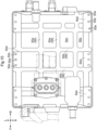
- the breathing hole 7 provided in the rear-facing wall portion 55R is located between the left and right front-back frames 2A in the left-right direction. Furthermore, as shown in FIG. 9 , the breathing hole 7 is located between the vertical line CL and the front-back frame 2A on the right side.
- the case lid 5B couplable to and uncouplable from the upper end portion of the case body 5A is constituted as follows.
- the case lid 5B has a large number of bolt insertion holes 58a (correspond to coupling holes) formed in a peripheral portion of the rectangular plate-shaped lid plate 58.
- the coupling bolts 57 are inserted into these bolt insertion holes 58a and a large number of screw holes 55d formed at the upper end portion of the peripheral wall portion 55 of the case body 5A, and the case lid 5B can be fastened with the case lid 5B facing the opening of the case body 5A.
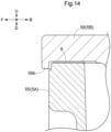
- a rib-shaped lip portion 58b that protrudes downward along the outer edge of the lid plate 58 is formed on the outer peripheral end portion of the lid plate 58.
- the lengths of the inner peripheral surface of the lip portion 58b in the front-back direction and the left-right direction are slightly larger than the lengths of the outer peripheral surface of the upper end portion of the peripheral wall portion 55 in the front-back direction and the left-right direction, such that the lip portion 58b externally fits to the upper end portion of the peripheral wall portion 55.
- the lip portion 58b fits together with the upper end of the peripheral wall portion 55 to partially overlap in the up-down direction. While the case lid 5B is thus externally fitted to the peripheral wall portion 55 of the case body 5A, the contact point between the upper end of the peripheral wall portion 55 of the case body 5A and the lower surface of the case lid 5B at a position facing the upper end thereof is higher than the lower end of the lip portion 58b corresponding to the lower peripheral portion of the case lid 5B.
- the case lid 5B is fixed in such a manner as to be externally fitted to the upper end portion of the peripheral wall portion 55 of the case body 5A.
- a resin gasket 8 interposed between the upper end of the peripheral wall portion 55 of the case body 5A and the outer peripheral end portion on the inner side of the lip portion 58b of the lid plate 58 is a resin gasket 8 as a sealing material that doubles as a cushioning material.
- the contact point between the upper end of the peripheral wall portion 55 of the case body 5A and the lower surface of the case lid 5B at a position facing the upper end of the peripheral wall portion 55 is higher than the lower end of the lip portion 58b corresponding to the lower peripheral portion of the case lid 5B, and thus the position of the gasket 8 interposed in that region is also higher than the lower end of the lip portion 58b corresponding to the lower peripheral portion of the case lid 5B.
- the gasket 8 is also effective in suppressing propagation of vibration from the case body 5A to the case lid 5B, and, conversely, propagation of vibration from the case lid 5B to the case body 5A.
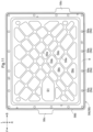
- the upper surface of the lid plate 58 that forms the case lid 5B is almost completely flat except for the periphery of the bolt insertion holes 58a, whiles on the lower surface of the lid plate 58 is formed a surface on which a large number of reinforcing ribs 56 are formed, as shown in FIG. 11 .
- the reinforcing ribs 56 are diagonal grid-shaped ribs 59a and 59b of the lid plate 58 that extend diagonally.
- the portion surrounded by the diagonal grid-shaped ribs 59a and 59b is an upward-facing recessed portion 59c that is recessed toward the upper surface of the case lid 5B.
- the lower surface of the lid plate 58 located between the diagonal grid-shaped ribs 59a and 59b is not formed to protrude lower than the lower end of the lip portion 58b, but, conversely, is formed as recessed wall surface provided, at various places, with the recessed portions 59c that are recessed to approach the upper surface of the lid plate 58.
- the diagonal grid-shaped ribs 59a and 59b are thus the portions that remain as reinforcing ribs 56, as a result of part of the lower surface of the lid plate 58 being recessed by providing the recessed portions 59c.
- the recess depth of the upward-facing recessed portion 59c corresponds to a distance d3 from the lower end to the upper end of the diagonal grid-shaped ribs 59a and 59b.
- the recessed portions 50c are formed to be shallower than the recessed portions 55c, by making this distance d3 shorter than the distance d1 (see FIG. 13 ) corresponding to the recess depth of the recessed portions 55c in the peripheral wall portion 55 described above.
- the diagonal grid-shaped ribs 59a and 59b are formed to extend in directions joining the bolt insertion holes 58a formed in the rectangular peripheral portion of the case lid 5B.
- part of the lower surface of the case lid 5B (inner surface of exterior case 5) has a region S 1 in which the diagonal grid-shaped ribs 59a and 59b protruding toward the inner space of the exterior case 5 are not provided.
- the diagonal grid-shaped ribs 59a and 59b extending in directions joining the bolt insertion holes 58a are formed in such a manner as to be interrupted partway between one bolt insertion hole 58a and another bolt insertion hole 58a.
- the far inner surface (lower surface of case lid 5B) of the region S 1 will be closer to the upper surface of the case lid 5B by the protruding height of the diagonal grid-shaped ribs 59a and 59b, and about the same position as the recess depth of the recessed portion 59c.
- This region S1 is provided to form an insulation distance securing space for allowing a distance for insulating purposes to be secured between the case lid 5B and components attached to the case body 5A at places facing the region S1.
- the case lid 5B is integrally molded with striking protrusions 58c that protrude outward from part of the outer peripheral portion of the lid plate 58.
- the striking protrusions 58c protrude horizontally outward from between the bolt insertion holes 58a (corresponds to bolt holes) formed on the periphery of the outer peripheral portion of the lid plate 58.
- the striking protrusions 58c also have ribs 58d (correspond to reinforcing ribs 56) that extend in the protruding direction of the striking protrusions 58c formed thereon (see FIGS. 6 and 9 ).
- case lid 5B When the case lid 5B is firmly coupled to the case body 5A by tightening down the coupling bolts 57 and is not opened or closed for an extended period of time, the case lid 5B may be difficult to open even when the coupling bolts 57 are removed, due to becoming stuck to the upper end of the case body 5A.
- the place where the case lid 5B and the upper end of the peripheral wall portion 55 fit together may be constituted as follows. That is, it is desirable that, between the inner peripheral surface of the lip portion 58b formed on the outer peripheral portion of the case lid 5B and the outer peripheral surface of the upper end portion of the peripheral wall portion 55, the inner peripheral surface of the lip portion 58b is set to a size that can be separated from the outer peripheral surface of the upper end portion of the peripheral wall portion 55, such that there at least is a slight horizontal gap, as shown in FIGS. 12 to 14 .
- the remaining configuration can be similar to the above-described embodiment.
- two substrates 60 are housed in the exterior case 5 as the inverter circuit 6, but the number of substrates 60 is not limited to two, and may be only one or may be three or more.
- the remaining configuration can be similar to the above-described embodiment.
- the exterior case 5 is constituted by a rectangular box-shaped case body 5A and a rectangular plate-shaped case lid 5B, but the exterior case 5 is not limited to being rectangular, and may be other shapes.
- the remaining configuration can be similar to the above-described embodiment.
- the grid-shaped reinforcing ribs 56 are formed on the entirety of the peripheral wall portion 55 and the bottom plate portion 50 of the case body 5A, but are not limited to this structure, and the reinforcing ribs 56 may be formed on only part of the peripheral wall portion 55 and the bottom plate portion 50 of the case body 5A.
- the remaining configuration can be similar to the above-described embodiment.
- the grid-shaped reinforcing ribs 56 are similarly formed on the entirety of the peripheral wall portion 55 and the bottom plate portion 50 of the case body 5A, but are not necessarily limited to this structure, and the reinforcing ribs 56 may be formed in an appropriate combination, such as the vertical rib 55a being formed on the left and right peripheral wall portions 55, the lateral rib 55b being formed on the front and rear peripheral wall portions 55, and the front-rear rib 50a being formed on the lower surface of the bottom plate portion 50.
- extension direction of the reinforcing ribs 56 is not limited to up/down, horizontal, front/back and left/right, and may be set as appropriate, such as diagonally or in any direction.
- the remaining configuration can be similar to the above-described embodiment.
- the reinforcing ribs 56 are materialized by forming the recessed portions 55c in the recess direction from a wall surface serving as a reference such as the outer peripheral edge of the upper end of the peripheral wall portion 55, but are not necessarily limited to this structure.
- reinforcing ribs 56 that protrude laterally outward from a reference wall surface such as the outer peripheral edge of the upper end of the peripheral wall portion 55 may be provided.
- the wall surface of the exterior case 5 may include a portion on which the reinforcing ribs 56 are not provided.
- the remaining configuration can be similar to the above-described embodiment.
- the diagonal grid-shaped ribs 59a and 59b extending in diagonal directions of the lid plate 58 are provided as reinforcing ribs 56 formed on the lower surface of the lid plate 58, but the reinforcing ribs 56 are not necessarily limited to this structure.
- grid-shaped reinforcing ribs 56 in which the front-back direction and the left-right direction intersect along the periphery of the lid plate 58 instead of the diagonal directions may be provided.
- diagonal reinforcing ribs 56 that extend along diagonal directions of the lid plate 58, longitudinal reinforcing ribs 56 that extend along the periphery of the lid plate 58, or lateral reinforcing ribs 56 that extend along the periphery of the lid plate 58 may be provided.
- the remaining configuration can be similar to the above-described embodiment.
- the reinforcing ribs 56 are formed only on the lower surface of the lid plate 58, but are not necessarily limited to this structure. Reinforcing ribs 56 having an appropriate structure can be employed, such as reinforcing ribs 56 formed only on the upper surface of the lid plate 58, or reinforcing ribs 56 formed on both the lower and upper surfaces of the lid plate 58.
- the remaining configuration can be similar to the above-described embodiment.
- the plurality of protruding pedestals 53 used as substrate stopping portions include protruding pedestals 53 having a high protruding height upward that are joined together by coupling ribs 54, but this structure need not necessarily be employed, and, for example, protruding pedestals 53 having a low protruding height may be coupled together, or low and high protruding pedestals 53 may be joined together.
- the remaining configuration can be similar to the above-described embodiment.
- the lip portion 58b protrudes downward from the periphery of the lid plate 58 by a constant amount, but is not necessarily limited to this structure, and the lip portion may protrude downward longer or shorter in places on the periphery of the lid plate 58.
- the amount of downward protrusion may be lengthened in places that are predicted to often be exposed to dust or rainwater from outside, such as increasing the amount of downward protrusion on the front side of the body, for example.
- the remaining configuration can be similar to the above-described embodiment.
- the lip portion 58b protrudes downward from the entire periphery of the lid plate 58, but is not necessarily limited to this structure, and there may be places on the periphery of the lid plate 58 where the lip portion 58b is not provided.
- the remaining configuration can be similar to the above-described embodiment.
- the invention can be utilized not only for tractors but also for various electric work vehicles such as combine harvesters, rice transplanters, and construction work machines.
Landscapes
- Engineering & Computer Science (AREA)
- Power Engineering (AREA)
- Transportation (AREA)
- Mechanical Engineering (AREA)
- Microelectronics & Electronic Packaging (AREA)
- Life Sciences & Earth Sciences (AREA)
- Sustainable Development (AREA)
- Sustainable Energy (AREA)
- Architecture (AREA)
- Civil Engineering (AREA)
- Structural Engineering (AREA)
- Environmental Sciences (AREA)
- Chemical & Material Sciences (AREA)
- Combustion & Propulsion (AREA)
- Arrangement Or Mounting Of Propulsion Units For Vehicles (AREA)
Abstract
Description
- The present invention relates to an electric work vehicle that includes a battery, a motor driven by electric power supplied from the battery, and a travel device driven by the motor.
- An electric work vehicle such as described above has already been disclosed in
Patent Document 1, for example. This electric work vehicle ("tractor" in Patent Document 1) has an inverter device ("inverter" in Patent Document 1) interposed on the power supply path from the battery to the electric motor. - Patent Document 1:
JP 2021-953A - The electric work vehicle having the structure shown in
Patent Document 1 has a reasonably sturdily support structure in which a large inverter support portion that is supported by left and right body frames is integrally formed with a relatively sturdily battery support base for supporting a large battery. Attaching the inverter device to the inverter support portion serving a sturdy support structure allows transmission of shaking, vibration and the like to the inverter device to be suppressed as much as possible. - However, in an electric work vehicle that performs various tasks, various shaking, vibration and the like may be transmitted to the inverter device due to a variety of external factors, such as vibration from the hydrostatic continuously variable transmission, vibration from the various work devices that are used, and shaking, vibration and the like that occur when traveling on uneven ground. Thus, there is room for improvement in terms of the difficulty in avoiding shaking, vibration and the like transmitted to the inverter device simply by improving the support strength of the place where the inverter device is installed.
- The invention aims to reduce the effects of shaking, vibration and the like transmitted to an inverter device by providing the inverter device itself with a vibration resistance function.
- Also,
Patent Document 1 merely shows the inverter device as a box-shaped body, and the specific structure thereof is not disclosed. - When the inverter device has a structure that merely combines a box-shaped body and a lid body, with an inverter circuit housed in the box-shaped body being accessed for maintenance purposes by opening the lid body, the region of the case body where the case lid opens and closes is required to be firmly sealed, so as to reliably avoid ingress of dust, rainwater, and the like from outside through this region. Furthermore, measures are also needed to avoid degradation of the sealing properties due to deterioration of the seal over time, and there is room for improvement in terms of the risk of adding complexity to the structure and making the opening/closing operation more troublesome.
- The invention further aims to provide an electric work vehicle in which ingress of dust, rainwater, and the like through the region where an exterior case used as an inverter device opens and closes is readily reliably avoided with a simple structure.
- An electric work vehicle of the invention is characterized by including:
- a battery;
- an electric motor configured to receive electric power from the battery;
- an inverter device interposed on a power supply path from the battery to the electric motor; and
- a travel device configured to be driven by the electric motor,
- the inverter device including an exterior case housing a substrate provided with an inverter circuit,
- the exterior case including:
- a rectangular box-shaped case body provided with an opening above a space surrounded by a bottom plate portion and a peripheral wall portion of the case body; and
- a case lid configured to open and close the opening, the bottom plate portion being provided, on an upper surface thereof, with a substrate stopping portion for fixing the substrate, and
- the case body being provided with at least one reinforcing rib formed on an outer surface of the peripheral wall portion, and the case lid being provided with at least one reinforcing rib formed on an inner surface thereof.
- According to the invention, the rigidity of the exterior case housing the substrate provided with the inverter circuit is enhanced by forming a reinforcing rib on the outer surface of the peripheral wall portion of the case body and on the inner surface of the case lid. A reduction in shaking, vibration and the like transmitted to the inverter device can thereby be achieved.
- Furthermore, the reinforcing rib formed on the exterior case is advantageous in terms of being able to enhance the heat dissipation effect obtained through contact with the outside air, as a result of being formed of the outer surface of the peripheral wall portion of the case body. Also, the reinforcing rib formed on the inner surface of the case lid helps strengthen the exterior case as a whole, while accumulation of dust is readily avoided and installation of the exterior case in the narrow space between the vehicle body frame and the battery installation base is facilitated, as a result of a reinforcing rib that protrudes upward not being provided on the upper surface of the case lid.
- In the invention, preferably the at least one reinforcing rib formed on the peripheral wall portion is at least one vertical rib extending in an up-down direction, and the at least one reinforcing rib formed on the inner surface of the case lid is at least one diagonal grid-shaped rib extending in a diagonal direction of the case lid.
- According to this configuration, high vertical and horizontal strength is readily maintained through combined use of a vertical rib extending in the up-down direction on the peripheral wall portion and a diagonal grid-shaped rib extending in the diagonal direction of the case lid on the inner surface of the case lid.
- In the invention, preferably the at least one vertical rib does not protrude outside an outer peripheral edge of an upper end of the peripheral wall portion, and the peripheral wall portion includes an outer wall surface between the vertical ribs positioned adjacent to each other that is formed as a recessed wall surface recessed to approach closer to an inner wall surface of the case body than is a place where the vertical ribs are formed.
- According to this configuration, the high vertical strength of the exterior case is maintained as a result of the vertical ribs, while securing a large surface area of the peripheral wall portion as a result of the outer wall surface located between the vertical ribs being formed as a recessed wall surface that is recessed to approach the inner wall surface of the case body. Heat is thereby readily efficiently dissipated, and weight reduction is readily achieved at the same time.
- In the invention, preferably the at least one vertical rib overlaps, in side view, with a screw hole formed in the peripheral wall portion in order to fasten the case lid to the case body.
- According to this configuration, as a result of the screw holes being formed in portions of the peripheral wall portion where the vertical ribs are provided, which portions are high-strength portions, the coupling strength between the case body and the case lid when fastened together is readily maintained high.
- In the invention, preferably the at least one diagonal grid-shaped rib extends in a direction joining coupling holes for bolt insertion formed in a rectangular peripheral portion of the case lid.
- According to this configuration, as a result of the diagonal grid-shaped rib on the case lid extending in a direction that joins coupling holes for bolt insertion, the diagonal grid-shaped rib acts like a brace while the case body and the case lid are fastened together, and the strength of the exterior case as a whole is readily enhanced.
- In the invention, preferably the inner surface of the case lid includes a region in which part of the at least one diagonal grid-shaped rib protruding into the space does not exist, and between the case lid and a component attached to the case body at a place facing the region is formed a space for securing an insulation distance.
- According to this configuration, when the exterior case is constituted by a conductive member, the provision of a region in which part of the diagonal grid-shaped rib protruding into the inner space of the case does not exist enables a space for securing an insulation distance to be formed between that region and a component facing that region.
- In the invention, preferably the bottom plate portion is provided, on a lower surface thereof, with a grid-shaped rib extending in the front-back direction and the left-right direction parallel to extension directions of the peripheral wall portion in plan view.
- According to this configuration, grid-shaped ribs extending in the front-back direction and the left-right direction are provided on the lower surface of the bottom plate portion, and the rigidity of the outer case is thus readily further increased.
- In the invention, preferably between an upper end surface of the peripheral wall portion of the case body and an inner surface of a peripheral portion of the case lid is sandwiched a cushioning material for vibration isolation.
- According to this configuration, as a result of a cushioning material for vibration isolation being sandwiched between the upper end surface of the peripheral wall portion of the case body and the inner surface of the peripheral portion of the case lid, propagation of vibration from the case body to the case lid is readily suppressed.
- In the invention, preferably the substrate stopping portion fixedly supports, on an upper surface of the bottom plate portion, a peripheral portion and a vicinity of a central portion of the substrate provided with the inverter circuit.
- According to this configuration, as a result of the peripheral portion and the vicinity of the center portion of the substrate being fixedly supported on the upper surface of the bottom plate portion, the substrate itself is less likely to flex, and shaking, vibration and the like are more readily suppressed.
- In the invention, preferably the substrate stopping portion includes a plurality of protruding pedestals for receiving and fastening the substrate, and the protruding pedestals positioned adjacent to each other are connected by a coupling rib.
- According to this configuration, the protruding pedestals of the substrate stopping portion are connected to each other by a coupling rib, and shaking, vibration and the like of the protruding pedestals are readily suppressed.
- Furthermore, an electric work vehicle of the invention is characterized by including:
- a battery;
- an electric motor configured to receive electric power from the battery;
- an inverter device interposed on a power supply path from the battery to the electric motor; and
- a travel device configured to be driven by the electric motor,
- the inverter device including an exterior case housing a substrate provided with an inverter circuit,
- the exterior case including:
- a rectangular box-shaped case body open at an upper end thereof; and
- a case lid configured to open and close the open upper end,
- the case body and the case lid being coupled together by a coupling bolt, and
- the case lid being provided, on a lower peripheral portion thereof, with a lip portion located on an outer side of an upper end portion of the case body and lower than the upper end portion.
- According to the invention, a lip portion located on the outer side of the upper end portion of the case body and lower than the upper end portion of the case body is formed on a lower peripheral portion of the case lid configured to open and close the open upper end of the case body. Accordingly, the open upper end of the case body can be closed, with the outer side of the contact point between the case body and the case lid surrounded by the lip portion, compared to a structure in which the case body and the case lid are merely coupled together by coupling bolts.
- Exposure of the contact point between the case body and the case lid to the outside can thereby be avoided, and ingress of dust, rainwater, and the like inside the exterior case from outside is thus readily prevented.
- In the invention, preferably the upper end of the case body and the case lid contact each other at a point higher than the lower peripheral portion of the case lid, and the contact point has a gasket interposed therein.
- According to this configuration, a gasket is provided at the contact point between the upper end of the case body and the case lid, at a higher position than the lower peripheral portion of the case lid, which portion is located on the outer side the upper end portion of the case body, and thus the possibility of this gasket coming into direct contact with dust, rainwater, and the like from outside is reduced. Ingress of dust, rainwater, and the like inside of the exterior case is thereby more readily prevented.
- In the invention, preferably the case lid is provided, on part of an outer peripheral portion thereof, with a striking protrusion protruding outward.
- According to this configuration, a striking protrusion that partially protrudes outward is formed on an outer peripheral portion of the case lid, and thus, if the case lid is difficult to open due to sticking to the upper end of the case body as a result of not been opened and closed for an extended period of time, this situation is readily resolved by striking the striking protrusion from outside.
- In the invention, preferably the striking protrusion protrudes horizontally outward from between bolt holes formed on a periphery of the outer peripheral portion of the case lid.
- According to this configuration, the striking protrusion protrudes horizontally outward from between the bolt holes formed on the periphery of the outer peripheral portion of the case lid, and thus the force generated by the striking action works effectively on the place where the degree of adhesion is high due to being firmly tightened by the coupling bolts, and the situation where the case lid is adhered to the case body is more readily resolved.
- In the invention, preferably the striking protrusion is provided with a reinforcing rib extending in a protruding direction of the striking protrusion.
- According to this configuration, the striking protrusion can be reinforced with a reinforcing rib, and the force generated by the striking action is readily accurately applied to the adhesion point between the case lid and the case body.
-
-
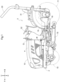
FIG. 1 is a left side view of a tractor. -
FIG. 2 is an illustrative diagram showing a power transmission mechanism from a battery to travel devices, a work device, and the like. -
FIG. 3 is a block diagram showing a power transmission system from a motor to travel devices and the like. -
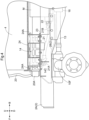
FIG. 4 is a partially cutaway side view showing an attachment point of an inverter. -
FIG. 5 is a front view showing a body frame and a battery installation base in cross-section, and showing the attachment point of the inverter. -
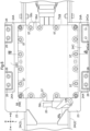
FIG. 6 is a plan view showing the battery installation base in cross-section and showing the attachment point of the inverter. -
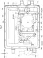
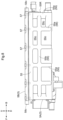
FIG. 7 is a plan view showing a case body of an exterior case of the inverter. -
FIG. 8 is a left side view showing the exterior case. -
FIG. 9 is a rear view showing the exterior case. -
FIG. 10 is a bottom view showing the case body of the exterior case. -
FIG. 11 is a bottom view showing a case lid of the exterior case. -
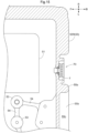
FIG. 12 is a cross-sectional view taken along line XII-XII inFIG. 6 . -
FIG. 13 is a cross-sectional view taken along line XIII-XIII inFIG. 6 . -
FIG. 14 is an enlarged cross-sectional view showing a lip portion of the case lid in vertical cross-section. -
FIG. 15 is an enlarged cross-sectional view showing a breathing hole in plan view. - Modes for carrying out the invention will be described with reference to the drawings. Note that, in the following description, unless otherwise noted, the direction of arrow F in the drawings is "forward", the direction of arrow B is "rearward", the direction of arrow L is "left", and the direction of arrow R is "right". Also, the direction of arrow U in the drawings is "up" and the direction of arrow D is "down".
- Hereinafter, a tractor of the present embodiment will be described. As shown in
FIG. 1 , the tractor includes left and rightfront wheels 10, left and rightrear wheels 11, and acover member 12. - Also, the tractor includes a
body frame 2 and adriving section 3. Thebody frame 2 is supported by the left and rightfront wheels 10 and the left and rightrear wheels 11. - The
cover member 12 is disposed in a front body portion. Thedriving section 3 is provided behind thecover member 12. In other words, thecover member 12 is disposed in front of thedriving section 3. - The
driving section 3 has aprotective frame 30, a driver'sseat 31, and asteering wheel 32. An operator can sit in the driver'sseat 31. The operator can thereby ride in thedriving section 3. The left and rightfront wheels 10 are steered by operating thesteering wheel 32. The operator is able to perform various driving operations in thedriving section 3. - The tractor is provided with a
travel battery 4. Also, thecover member 12 is pivotable about an opening-closing axis Q extending the left-right direction of the body. Thecover member 12 is thereby openable and closable. While thecover member 12 is closed, thetravel battery 4 is covered by thecover member 12. - As shown in
FIG. 2 , the tractor includes an inverter 14 (corresponds to inverter device) and a motor M. Thetravel battery 4 supplies electric power to theinverter 14. Theinverter 14 converts DC power from thetravel battery 4 into AC power and supplies the AC power to the motor M. The motor M is then driven by the AC power supplied from theinverter 14. - As shown in
FIGS. 2 and3 , the tractor includes a hydrostatic continuously variable transmission (CVT) 15 and atransmission 16. As shown inFIG. 3 , thehydrostatic CVT 15 has ahydraulic pump 15a and ahydraulic motor 15b. - The
hydraulic pump 15a is driven by rotational power from the motor M. Rotational power is output from thehydraulic motor 15b, in response to thehydraulic pump 15a being driven. Note that, in thehydrostatic CVT 15, rotational power is varied between thehydraulic pump 15a and thehydraulic motor 15b. Also, the transmission ratio of thehydrostatic CVT 15 can be changed continuously. - The rotational power output from the
hydraulic motor 15b is transmitted to thetransmission 16. The rotational power transmitted to thetransmission 16 is varied by a geared transmission mechanism of thetransmission 16 and distributed to the left and rightfront wheels 10 and the left and rightrear wheels 11. The left and rightfront wheels 10 and the left and rightrear wheels 11 are thereby driven. - Also, as shown in
FIGS. 2 and3 , the tractor includes a mid power takeoff (PTO)shaft 17 and a rear power takeoff (PTO)shaft 18. The rotational power output from the motor M is distributed to thehydraulic pump 15a, themid PTO shaft 17, and therear PTO shaft 18. Themid PTO shaft 17 and therear PTO shaft 18 thereby rotate. - If a work device is connected to the mid PTO shaft 17 (or the rear PTO shaft 18), the work device will be driven by the rotational power of the mid PTO shaft 17 (or the rear PTO shaft 18). For example, as shown in
FIG. 2 , in the present embodiment, amowing device 19 is connected to themid PTO shaft 17. Themowing device 19 is driven by the rotational power of themid PTO shaft 17. - As shown in
FIGS. 4 and5 , thebody frame 2 includes left and right front-back frames 2A and alateral frame 2B. The left and right front-back frames 2A extend in the front-back direction of the body, and thelateral frame 2B joins the left and right front-back frames 2A to each other. Thelateral frame 2B is coupled to lower portions of the left and right front-back frames 2A, and extends in the front-back direction in a plan view from the region where the front end portion of theinverter 14 is located to the region where the front end portion of the motor M is located. - The
lateral frame 2B is coupled to anaxle unit 10F extending in the left-right direction of the body of the tractor (corresponds to electric work vehicle).
Thefront wheels 10 are rotationally supported by left and right end portions of theaxle unit 10F. Also, thetransmission 16 and theaxle unit 10F are coupled to apropeller shaft 13 extending in the front-back direction of the body below thelateral frame 2B. - The
inverter 14 and the motor M are disposed adjacent to each other in the front-back direction. In other words, theinverter 14 and the motor M are aligned with each other in the front-back direction of the body. The motor M and theinverter 14 are supported by the left and right front-back frames 2A in such a manner as to be aligned with each other in the front-back direction of the body between the left and right front-back frames 2A. Theinverter 14 is in front of the motor M. - The
inverter 14 and the motor M are connected by apower supply cable 21. Thepower supply cable 21 is detachably connected at oneend portion 21A to anoutput connector 14C of theinverter 14, and is detachably connected at anopposite end 21B to apower receiving connector 22 of the motor M. - The
output connector 14C is located in a region of theexterior case 5 on the opposite side to the motor M. Thepower supply cable 21 is located above thelateral frame 2B and is housed between the left and right front-back frames 2A. That is, thepower supply cable 21 extends in the front-back direction through the space surrounded by the left and right front-back frames 2A, thelateral frame 2B, and abottom plate portion 50 of theexterior case 5. The possibility of theoutput connector 14C and thepower supply cable 21 coming into contact with foreign objects is thereby avoided, and the possibility of theoutput connector 14C and thepower supply cable 21 becoming detached in response to coming into contact with foreign objects can be reduced. - The
travel battery 4 is supported by the left and right front-back frames 2A in such a manner as to be located directly above theinverter 14. Specifically, as shown inFIGS. 4 to 6 , on upper end portions of the left and right front-back frames 2A are respectively formed left and rightsupport surface portions 23. On the left and rightsupport surface portions 23 is placed abattery installation base 24, and thetravel battery 4 is placed on thebattery installation base 24. - The left and right
support surface portions 23 extend in the lateral direction of the body at upper end portions of the left and right front-back frames 2A. Note that, as shown inFIGS. 4 and5 ,triangular ribs 27 extend between thesupport surface portions 23 and the front-back frames 2A to prevent the left and rightsupport surface portions 23 from sagging with respect to the left and right front-back frames 2A. Thetriangular ribs 27 are welded, at contact sides thereof, to the front-back frames 2A and thesupport surface portions 23, and thesupport surface portions 23 are thereby integrally formed with the front-back frames 2A via thetriangular ribs 27, and constitute part of thebody frame 2. The bottom portion of theinverter 14 is coupled to thesupport surface portions 23 byattachment bolts 28. Theinverter 14 is thus removably supported by thebody frame 2. - The
battery installation base 24 is bolted to the left and rightsupport surface portions 23. As shown inFIGS. 4 to 6 , thebattery installation base 24 is formed by welding togetherattachment plates 24C that respectively partially overlap with the left and rightsupport surface portions 23, C-shaped steelvertical frames 24A that extends in the up-down direction on theattachment plates 24C, left and right steel angles 24B that extend in the front-back direction of the body at upper end portions of the left and rightvertical frames 24A, and a lateral steel angle that joins the left and right steel angles 24B extending in the front-back direction of the body. - The
attachment plates 24C have bolt insertion holes 24Ca for bolting theattachment plates 24C to thesupport surface portions 23 formed therein, and theattachment plates 24C and thesupport surface portions 23 can be fixedly coupled together via couplingbolts 26. Thebattery installation base 24 is gate shaped as viewed in the front-back direction of the body. Thebattery installation base 24 covers theinverter 14 from above and from the left and right sides. - Left and right side portions of upper portions of the steel angles 24B are bolted to lower portions of
coupling plates 25. Also, left and right side portions of lower portions of thetravel battery 4 are bolted to upper portions of thecoupling plates 25. Thetravel battery 4 is thereby coupled to thebattery installation base 24 via thecoupling plates 25. - The
inverter 14 of the present embodiment will now be described with reference toFIGS. 4 to 15 . Theinverter 14 converts direct current from thetravel battery 4 into alternating current and supplies the alternating current to the motor M. - As shown in
FIGS. 7 ,12 , and13 , theinverter 14 houses asubstrate 60 on which an inverter circuit 6 is provided, acapacitor 61, and the like in theexterior case 5 which includes acase body 5A and acase lid 5B. - The inverter circuit 6 is a circuit body that converts direct current from the
travel battery 4 into alternating current, and is provided with an inverter module constituted by an insulated gate bipolar transistor (IGBT), for example, and by an inverter control module that communicates with a higher-order electronic control unit (ECU) and controls the inverter module. Thecapacitor 61 holds the supply voltage for the inverter module at a constant voltage. - The
substrate 60 includes afirst substrate 60A on which the inverter module is provided and asecond substrate 60B on which the inverter control module is provided. - As shown in
FIGS. 12 and13 , on thebottom plate portion 50 of thecase body 5A is provided a firstsubstrate stopping portion 51 for fixing thefirst substrate 60A. - Also, a second
substrate stopping portion 52 is provided for fixing thesecond substrate 60B, which is adifferent substrate 60 from thefirst substrate 60A, at a position overlapping thefirst substrate 60A from above. - The first
substrate stopping portion 51 includes protrudingpedestals 53 for receiving a peripheral portion and a central portion of thefirst substrate 60A and fixing the peripheral and central portions of thefirst substrate 60A to thebottom plate portion 50. The peripheral and central portions of thefirst substrate 60A are fixed to thebottom plate portion 50, using screw holes provided in the protruding pedestals 53 and set screws, with the protruding pedestals 53 positioned to face the peripheral and central portions of thefirst substrate 60A. - The second
substrate stopping portion 52 includes anattachment plate 62 capable of supporting a peripheral portion and a central portion of thesecond substrate 60B, and protrudingpedestals 53 for receiving a peripheral portion of theattachment plate 62 and fixing the peripheral portion of theattachment plate 62 to thebottom plate portion 50. The peripheral and central portions of thesecond substrate 60B supported by theattachment plate 62 are fixed to thebottom plate portion 50, as a result of theattachment plate 62 being fixed to thebottom plate portion 50, using screw holes provided in the protruding pedestals 53 and set screws, with the protruding pedestals 53 positioned to face the peripheral portion of theattachment plate 62, while the peripheral and central portions of thesecond substrate 60B are supported by theattachment plate 62. - As shown in
FIGS. 7 and15 , some of the adjacently positioned protrudingpedestals 53 are connected to each other by couplingribs 54. The protruding pedestals 53 having a high protruding height upward from thebottom plate portion 50 and are for fixing theattachment plate 62 to thebottom plate portion 50 are connected to each other and to the inner surface of thecase body 5A described later by thecoupling ribs 54. Shaking of the protruding pedestals 53 having a high protruding height from thebottom plate portion 50 is thereby readily effectively suppressed. As a result, transmission of shaking, vibration and the like to theattachment plate 62 and thesecond substrate 60B fixed to theattachment plate 62 are readily reduced. - The
travel battery 4 and theinverter 14 are electrically connected to each other by a power cable 20 (corresponds to input harness). Direct current flows through thepower cable 20. As shown inFIGS. 4 and6 , theinverter 14 is provided with aninput connector 14B (corresponds to input connection portion). Theinput connector 14B protrudes forward of a front portion of theexterior case 5 and is electrically connected to aconnection port 20A of thepower cable 20. - In this way, the
inverter 14 includes theinput connector 14B electrically connected to thepower cable 20, the inverter circuit 6 that converts direct current into alternating current, and theoutput connector 14C (output connection portion) electrically connected to the power supply cable 21 (corresponds to the output harness). - The
exterior case 5 is an aluminum die-cast product that includes thecase body 5A having a rectangular box shape and thecase lid 5B having a rectangular plate shape. - The rectangular box-shaped
case body 5A includes thebottom plate portion 50 and aperipheral wall portion 55, and the space surrounded by thebottom plate portion 50 and theperipheral wall portion 55 is open upward. Thecase lid 5B is couplable to and uncouplable from an upper end portion of thecase body 5A, in such a manner that the opening in thecase body 5A is openable and closable. - The first
substrate stopping portion 51 and the secondsubstrate stopping portion 52 for fixing thesubstrate 60 are provided on thebottom plate portion 50 of thecase body 5A. The inverter circuit 6 is housed in theexterior case 5 by closing the opening of thecase body 5A with thecase lid 5B, with thefirst substrate 60A and thesecond substrate 60B respectively attached to the firstsubstrate stopping portion 51 and the secondsubstrate stopping portion 52. - As shown in
FIGS. 8 and9 , on the outer wall surface of theperipheral wall portion 55 of thecase body 5A are formed grid-shaped reinforcingribs 56 includingvertical ribs 55a that extend in the up-down direction andlateral ribs 55b that extend in the horizontal direction. - As shown in
FIG. 7 , the reinforcingribs 56 are formed in such a manner that thevertical ribs 55a and thelateral ribs 55b do not protrude outside the outer peripheral edge of the upper end of theperipheral wall portion 55. The outer wall surface between the adjacentvertical ribs 55a is formed as a recessed wall surface provided, at various places, with recessedportions 55c that are recessed to approach closer to the inner wall surface of thecase body 5A than are places where thevertical ribs 55a are formed. - That is, as shown in
FIGS. 7 to 9 ,12 , and13 , thevertical ribs 55a and thelateral ribs 55b are not formed to protrude outward of the outer peripheral edge of the upper end of theperipheral wall portion 55, but, conversely, are the portions that remain as reinforcingribs 56, as a result of theperipheral wall portion 55 being formed in such a manner that part of the outer wall surface thereof is recessed by providing the recessedportions 55c. - As shown in
FIGS. 7 and13 , in an upper end portion of theperipheral wall portion 55 are formedscrew holes 55d into whichcoupling bolts 57 for fastening thecase lid 5B while thecase lid 5B faces the opening in thecase body 5A are screwable. As shown inFIGS. 7 and8 , the screw holes 55d are formed at positions that overlap with thevertical ribs 55a in side view. - As a result of the screw holes 55d thus being formed in the places where the
vertical ribs 55a are provided, the strength of the places where thecase lid 5B is coupled to thecase body 5A is enhanced, by effectively utilizing the places where thevertical ribs 55a are formed, which are where theperipheral wall portion 55 of thecase body 5A is horizontally thick. - As shown in
FIGS. 7 ,12 , and13 , the recess depth of the recessedportions 55c corresponds to a distance d1 from the outer end to the inner end of thevertical ribs 55a. As a result, the far inner portion of the recessedportions 55c is formed to approach closer to the inner wall surface of theperipheral wall portion 55 than are the places where thecoupling bolts 57 are provided. By thus increasing the recess depth of the recessedportion 55c, the wall thickness of theperipheral wall portion 55 at places where the recessedportions 55c are formed is reduced, and weight reduction of thecase body 5A is achieved. - On the
peripheral wall portion 55 of thecase body 5A, the grid-shaped reinforcingribs 56 are formed not only on the left side surface shown inFIG. 8 and the rear surface shown inFIG. 9 , but are also similarly formed on the front surface shown inFIG. 5 and on the right side surface which is not shown. - As shown in
FIG. 10 , on the lower surface of thebottom plate portion 50 of thecase body 5A is formed reinforcingribs 56 including front-rear ribs 50a extending in the front-back direction and left-right ribs 50b extending in the left-right direction. - At both left and right end portions of the
bottom plate portion 50 are providedattachment seats 50d for fixing thecase body 5A to thesupport surface portions 23 of the front-back frames 2A. These attachment seats 50d are provided withattachment holes 50e for fixing via theattachment bolt 28. - The front-
rear ribs 50a and the left-right ribs 50b are also formed by providing upward-facing recessedportions 50c in the place surrounded by the front-rear ribs 50a and the left-right ribs 50b, rather than being formed to protrude lower than the lower surface of theattachment seat 50d provided at the lower end of the outer peripheral edge of thebottom plate portion 50. - The recess depth of the upward-facing recessed
portion 50c corresponds to a distance d2 from the lower end to the upper end of the front-rear ribs 50a and the left-right ribs 50b. The recessedportions 50c are formed to be shallower than the recessedportions 55c, by making this distance d2 shorter than the distance d1 (seeFIG. 13 ) corresponding to the recess depth of the recessedportions 55c in theperipheral wall portion 55 described above. - The
peripheral wall portion 55 of thecase body 5A includes a rear-facingwall portion 55R that faces the rearward side of the body and is provided with abreathing hole 7 for ventilation through which air inside theexterior case 5 can be exhausted. - This
breathing hole 7 is provided with afilter 70 to allow internal air to be exhausted following a rise in air pressure within theexterior case 5 due to factors such as heat generated by the inverter circuit 6, and to restrict ingress of dust, rainwater, and the like from outside. - As shown in
FIGS. 5 and9 , theexterior case 5 is installed on the front-back frames 2A so as to be allocated on the left and right of a vertical line CL that passes through a central position between the left and right front-back frames 2A in the left-right direction, that is, a central position in the left-right direction of the body. The vertical line CL intersects an axis (not shown) of theaxle unit 10F of thefront wheels 10 that extends in the front-back direction as viewed in the front-back direction of the body. Accordingly, theexterior case 5 is installed on the front-back frames 2A in the vicinity of the place where shake of the front-back frames 2A in the left-right direction when thefront wheels 10 are rolling about the axis extending in the front-back direction is minimal. - As shown in
FIGS. 4 and5 , thetravel battery 4 is located above theexterior case 5, and theexterior case 5 is covered by thetravel battery 4 and thebattery installation base 24 for installing thetravel battery 4. Thelateral frame 2B that joins the left and right front-back frames 2A and thesupport surface portions 23 provided on the upper edge of the front-back frames 2A are located below theexterior case 5. The lower side of theexterior case 5 is thereby blocked by the left-rightlateral frame 2B and thesupport surface portions 23. - Even though the
vertical frames 24A of thebattery installation base 24 are provided laterally outward of theexterior case 5, large portions of theexterior case 5 are exposed laterally outward. - The
breathing hole 7 provided in the rear-facingwall portion 55R is located between the left and right front-back frames 2A in the left-right direction. Furthermore, as shown inFIG. 9 , thebreathing hole 7 is located between the vertical line CL and the front-back frame 2A on the right side. - The
case lid 5B couplable to and uncouplable from the upper end portion of thecase body 5A is constituted as follows. - As shown in
FIG. 11 , thecase lid 5B has a large number ofbolt insertion holes 58a (correspond to coupling holes) formed in a peripheral portion of the rectangular plate-shapedlid plate 58. Thecoupling bolts 57 are inserted into thesebolt insertion holes 58a and a large number ofscrew holes 55d formed at the upper end portion of theperipheral wall portion 55 of thecase body 5A, and thecase lid 5B can be fastened with thecase lid 5B facing the opening of thecase body 5A. - As shown in
FIGS. 11 to 14 , a rib-shapedlip portion 58b that protrudes downward along the outer edge of thelid plate 58 is formed on the outer peripheral end portion of thelid plate 58. - In this
lip portion 58b, the lengths of the inner peripheral surface of thelip portion 58b in the front-back direction and the left-right direction are slightly larger than the lengths of the outer peripheral surface of the upper end portion of theperipheral wall portion 55 in the front-back direction and the left-right direction, such that thelip portion 58b externally fits to the upper end portion of theperipheral wall portion 55. - As a result, as shown in
FIGS. 12 to 14 , with thelid plate 58 placed on the upper side of theperipheral wall portion 55 of thecase body 5A, thelip portion 58b fits together with the upper end of theperipheral wall portion 55 to partially overlap in the up-down direction. While thecase lid 5B is thus externally fitted to theperipheral wall portion 55 of thecase body 5A, the contact point between the upper end of theperipheral wall portion 55 of thecase body 5A and the lower surface of thecase lid 5B at a position facing the upper end thereof is higher than the lower end of thelip portion 58b corresponding to the lower peripheral portion of thecase lid 5B. - By inserting the
coupling bolts 57 into thebolt insertion holes 58a in thelid plate 58 and thescrew holes 55d in theperipheral wall portion 55 and tightening thecoupling bolts 57 in the above state, thecase lid 5B is fixed in such a manner as to be externally fitted to the upper end portion of theperipheral wall portion 55 of thecase body 5A. - As shown in
FIGS. 11 and14 , interposed between the upper end of theperipheral wall portion 55 of thecase body 5A and the outer peripheral end portion on the inner side of thelip portion 58b of thelid plate 58 is aresin gasket 8 as a sealing material that doubles as a cushioning material. - As described above, the contact point between the upper end of the
peripheral wall portion 55 of thecase body 5A and the lower surface of thecase lid 5B at a position facing the upper end of theperipheral wall portion 55 is higher than the lower end of thelip portion 58b corresponding to the lower peripheral portion of thecase lid 5B, and thus the position of thegasket 8 interposed in that region is also higher than the lower end of thelip portion 58b corresponding to the lower peripheral portion of thecase lid 5B. - As shown in
FIG. 11 , in thegasket 8 are formed throughholes 8a through which thecoupling bolts 57 can be inserted, at the same position as thebolt insertion hole 58a of thelid plate 58. Once fixing with thecoupling bolts 57 is performed with thegasket 8 interposed between the upper end of theperipheral wall portion 55 and the outer peripheral end portion on the inner side of thelip portion 58b of thelid plate 58, dust, rainwater, and the like entering theexterior case 5 from outside is readily reliably suppressed as a result of the multiplier effect of suppressing entry of dust, rainwater, and the like as a result of the presence of thelip portion 58b and the sealing effect of thegasket 8. - The
gasket 8 is also effective in suppressing propagation of vibration from thecase body 5A to thecase lid 5B, and, conversely, propagation of vibration from thecase lid 5B to thecase body 5A. - As shown in
FIG. 6 , the upper surface of thelid plate 58 that forms thecase lid 5B is almost completely flat except for the periphery of thebolt insertion holes 58a, whiles on the lower surface of thelid plate 58 is formed a surface on which a large number of reinforcingribs 56 are formed, as shown inFIG. 11 . The reinforcingribs 56 are diagonal grid-shapedribs lid plate 58 that extend diagonally. - In
FIG. 11 , the portion surrounded by the diagonal grid-shapedribs portion 59c that is recessed toward the upper surface of thecase lid 5B. - That is, as shown in
FIGS. 12 and13 , the lower surface of thelid plate 58 located between the diagonal grid-shapedribs lip portion 58b, but, conversely, is formed as recessed wall surface provided, at various places, with the recessedportions 59c that are recessed to approach the upper surface of thelid plate 58. The diagonal grid-shapedribs ribs 56, as a result of part of the lower surface of thelid plate 58 being recessed by providing the recessedportions 59c. - The recess depth of the upward-facing recessed
portion 59c corresponds to a distance d3 from the lower end to the upper end of the diagonal grid-shapedribs portions 50c are formed to be shallower than the recessedportions 55c, by making this distance d3 shorter than the distance d1 (seeFIG. 13 ) corresponding to the recess depth of the recessedportions 55c in theperipheral wall portion 55 described above. - The diagonal grid-shaped
ribs bolt insertion holes 58a formed in the rectangular peripheral portion of thecase lid 5B. - As shown in
FIG. 11 , part of the lower surface of thecase lid 5B (inner surface of exterior case 5) has aregion S 1 in which the diagonal grid-shapedribs exterior case 5 are not provided. - In this region S1, the diagonal grid-shaped
ribs bolt insertion holes 58a are formed in such a manner as to be interrupted partway between onebolt insertion hole 58a and anotherbolt insertion hole 58a. In this region S1, as a result of there being no diagonal grid-shapedribs case lid 5B) of theregion S 1 will be closer to the upper surface of thecase lid 5B by the protruding height of the diagonal grid-shapedribs portion 59c. - This region S1 is provided to form an insulation distance securing space for allowing a distance for insulating purposes to be secured between the
case lid 5B and components attached to thecase body 5A at places facing the region S1. - The
case lid 5B is integrally molded withstriking protrusions 58c that protrude outward from part of the outer peripheral portion of thelid plate 58. - The
striking protrusions 58c protrude horizontally outward from between thebolt insertion holes 58a (corresponds to bolt holes) formed on the periphery of the outer peripheral portion of thelid plate 58. Thestriking protrusions 58c also haveribs 58d (correspond to reinforcing ribs 56) that extend in the protruding direction of thestriking protrusions 58c formed thereon (seeFIGS. 6 and9 ). - When the
case lid 5B is firmly coupled to thecase body 5A by tightening down thecoupling bolts 57 and is not opened or closed for an extended period of time, thecase lid 5B may be difficult to open even when thecoupling bolts 57 are removed, due to becoming stuck to the upper end of thecase body 5A. - At this time, by striking the
striking protrusions 58c from outside, the adhesion between thecase lid 5B and thecase body 5A is released, and thecase lid 5B is readily opened. When thestriking protrusions 58c are struck from outside, there is also a possibility of thestriking protrusions 58c being slightly deformed or damaged depending on the extent of the strike, due to being aluminum die-cast products, but there is little risk of thecase lid 5B portion, which is the main component of theexterior case 5 apart from thestriking protrusions 58c, being deformed or damaged. - Also, in order to effectively exhibit the action of releasing the adhesion to the
case lid 5B by striking thestriking protrusions 58c from outside, the place where thecase lid 5B and the upper end of theperipheral wall portion 55 fit together may be constituted as follows. That is, it is desirable that, between the inner peripheral surface of thelip portion 58b formed on the outer peripheral portion of thecase lid 5B and the outer peripheral surface of the upper end portion of theperipheral wall portion 55, the inner peripheral surface of thelip portion 58b is set to a size that can be separated from the outer peripheral surface of the upper end portion of theperipheral wall portion 55, such that there at least is a slight horizontal gap, as shown inFIGS. 12 to 14 . - Hereinafter, other embodiments will be shown. The following embodiments may be used in combination as long as no there are no inconsistencies. Note that the scope of the invention is not limited to the contents of these embodiments.
- (1) In the example illustrated in the above-described embodiment, the
exterior case 5 is an aluminum die-cast product, but need not necessarily be an aluminum die-cast product, and may, for example, be a cast iron product or may be made of another material. - The remaining configuration can be similar to the above-described embodiment.
- (2) In the example illustrated in the above-described embodiment, two
substrates 60 are housed in theexterior case 5 as the inverter circuit 6, but the number ofsubstrates 60 is not limited to two, and may be only one or may be three or more. - The remaining configuration can be similar to the above-described embodiment.
- (3) In the example illustrated in the above-described embodiment, the
exterior case 5 is constituted by a rectangular box-shapedcase body 5A and a rectangular plate-shapedcase lid 5B, but theexterior case 5 is not limited to being rectangular, and may be other shapes. - The remaining configuration can be similar to the above-described embodiment.
- (4) In the example illustrated in the above-described embodiment, the grid-shaped reinforcing
ribs 56 are formed on the entirety of theperipheral wall portion 55 and thebottom plate portion 50 of thecase body 5A, but are not limited to this structure, and the reinforcingribs 56 may be formed on only part of theperipheral wall portion 55 and thebottom plate portion 50 of thecase body 5A. - The remaining configuration can be similar to the above-described embodiment.
- (5) In the example illustrated in the above-described embodiment, the grid-shaped reinforcing
ribs 56 are similarly formed on the entirety of theperipheral wall portion 55 and thebottom plate portion 50 of thecase body 5A, but are not necessarily limited to this structure, and the reinforcingribs 56 may be formed in an appropriate combination, such as thevertical rib 55a being formed on the left and rightperipheral wall portions 55, thelateral rib 55b being formed on the front and rearperipheral wall portions 55, and the front-rear rib 50a being formed on the lower surface of thebottom plate portion 50. - Also, the extension direction of the reinforcing
ribs 56 is not limited to up/down, horizontal, front/back and left/right, and may be set as appropriate, such as diagonally or in any direction. - The remaining configuration can be similar to the above-described embodiment.
- (6) In the example illustrated in the above-described embodiment, the reinforcing
ribs 56 are materialized by forming the recessedportions 55c in the recess direction from a wall surface serving as a reference such as the outer peripheral edge of the upper end of theperipheral wall portion 55, but are not necessarily limited to this structure. For example, reinforcingribs 56 that protrude laterally outward from a reference wall surface such as the outer peripheral edge of the upper end of theperipheral wall portion 55 may be provided. - Also, the wall surface of the
exterior case 5 may include a portion on which the reinforcingribs 56 are not provided. - The remaining configuration can be similar to the above-described embodiment.
- (7) In the example illustrated in the above-described embodiment, the diagonal grid-shaped
ribs lid plate 58 are provided as reinforcingribs 56 formed on the lower surface of thelid plate 58, but the reinforcingribs 56 are not necessarily limited to this structure. For example, grid-shaped reinforcingribs 56 in which the front-back direction and the left-right direction intersect along the periphery of thelid plate 58 instead of the diagonal directions may be provided. Also, instead of grid-shaped reinforcingribs 56, diagonal reinforcingribs 56 that extend along diagonal directions of thelid plate 58, longitudinal reinforcingribs 56 that extend along the periphery of thelid plate 58, orlateral reinforcing ribs 56 that extend along the periphery of thelid plate 58 may be provided. - The remaining configuration can be similar to the above-described embodiment.
- (8) In the example illustrated in the above-described embodiment, the reinforcing
ribs 56 are formed only on the lower surface of thelid plate 58, but are not necessarily limited to this structure. Reinforcingribs 56 having an appropriate structure can be employed, such as reinforcingribs 56 formed only on the upper surface of thelid plate 58, or reinforcingribs 56 formed on both the lower and upper surfaces of thelid plate 58. - The remaining configuration can be similar to the above-described embodiment.
- (9) In the example illustrated in the above-described embodiment, the plurality of protruding
pedestals 53 used as substrate stopping portions include protrudingpedestals 53 having a high protruding height upward that are joined together by couplingribs 54, but this structure need not necessarily be employed, and, for example, protrudingpedestals 53 having a low protruding height may be coupled together, or low and high protruding pedestals 53 may be joined together. - The remaining configuration can be similar to the above-described embodiment.
- (10) In the example illustrated in the above-described embodiment, the
lip portion 58b protrudes downward from the periphery of thelid plate 58 by a constant amount, but is not necessarily limited to this structure, and the lip portion may protrude downward longer or shorter in places on the periphery of thelid plate 58. In this case, the amount of downward protrusion may be lengthened in places that are predicted to often be exposed to dust or rainwater from outside, such as increasing the amount of downward protrusion on the front side of the body, for example. - The remaining configuration can be similar to the above-described embodiment.
- (11) In the example illustrated in the above-described embodiment, the
lip portion 58b protrudes downward from the entire periphery of thelid plate 58, but is not necessarily limited to this structure, and there may be places on the periphery of thelid plate 58 where thelip portion 58b is not provided. - The remaining configuration can be similar to the above-described embodiment.
- The invention can be utilized not only for tractors but also for various electric work vehicles such as combine harvesters, rice transplanters, and construction work machines.
-
- 2 Body frame
- 4 Battery
- 5 Exterior case
- 5A Case body
- 5B Case lid
- 6 Inverter circuit
- 8 Cushioning material (gasket)
- 10, 11 Travel device
- 14 Inverter
- 50 Bottom plate
- 50a, 50b Grid-shaped rib
- 51 First substrate stopping portion (substrate stopping portion)
- 52 Second substrate stopping portion (substrate stopping portion)
- 53 Protruding pedestal
- 54 Coupling rib
- 55 Peripheral wall portion
- 55a Vertical rib
- 55d Screw hole
- 56 Reinforcing rib
- 58a Coupling hole
- 58b Folded portion
- 58c Striking protrusion
- 58d Reinforcing rib
- 59a, 59b Diagonal grid-shaped rib
- 60 Substrate
- M Electric motor
- S1 Region
Claims (15)
- An electric work vehicle comprising:a battery;an electric motor configured to receive electric power from the battery;an inverter device interposed on a power supply path from the battery to the electric motor; anda travel device configured to be driven by the electric motor,the inverter device including an exterior case housing a substrate provided with an inverter circuit,the exterior case including:a rectangular box-shaped case body provided with an opening above a space surrounded by a bottom plate portion and a peripheral wall portion of the case body; anda case lid configured to open and close the opening,the bottom plate portion being provided, on an upper surface thereof, with a substrate stopping portion for fixing the substrate, andthe case body being provided with at least one reinforcing rib formed on an outer surface of the peripheral wall portion, and the case lid being provided with at least one reinforcing rib formed on an inner surface thereof.
- The electric work vehicle according to claim 1,
wherein the at least one reinforcing rib formed on the peripheral wall portion is at least one vertical rib extending in an up-down direction, and the at least one reinforcing rib formed on the inner surface of the case lid is at least one diagonal grid-shaped rib extending in a diagonal direction of the case lid. - The electric work vehicle according to claim 2,
wherein the at least one vertical rib does not protrude outside an outer peripheral edge of an upper end of the peripheral wall portion, and
the peripheral wall portion includes an outer wall surface between the vertical ribs positioned adjacent to each other that is formed as a recessed wall surface recessed to approach closer to an inner wall surface of the case body than is a place where the vertical ribs are formed. - The electric work vehicle according to claim 2 or 3,
wherein the at least one vertical rib overlaps, in side view, with a screw hole formed in the peripheral wall portion in order to fasten the case lid to the case body. - The electric work vehicle according to any one of claims 2 to 4,
wherein the at least one diagonal grid-shaped rib extends in a direction joining coupling holes for bolt insertion formed in a rectangular peripheral portion of the case lid. - The electric work vehicle according to any one of claims 2 to 5,
wherein the inner surface of the case lid includes a region in which part of the at least one diagonal grid-shaped rib protruding into the space does not exist, and between the case lid and a component attached to the case body at a place facing the region is formed a space for securing an insulation distance. - The electric work vehicle according to any one of claims 1 to 6,
wherein the bottom plate portion is provided, on a lower surface thereof, with a grid-shaped rib extending in the front-back direction and the left-right direction parallel to extension directions of the peripheral wall portion in plan view. - The electric work vehicle according to any one of claims 1 to 7,
wherein between an upper end surface of the peripheral wall portion of the case body and an inner surface of a peripheral portion of the case lid is sandwiched a cushioning material for vibration isolation. - The electric work vehicle according to any one of claims 1 to 8,
wherein the substrate stopping portion fixedly supports, on an upper surface of the bottom plate portion, a peripheral portion and a vicinity of a central portion of the substrate provided with the inverter circuit. - The electric work vehicle according to any one of claims 1 to 9,wherein the substrate stopping portion includes a plurality of protruding pedestals for receiving and fastening the substrate, andthe protruding pedestals positioned adjacent to each other are connected by a coupling rib.
- An electric work vehicle comprising:a battery;an electric motor configured to receive electric power from the battery;an inverter device interposed on a power supply path from the battery to the electric motor; anda travel device configured to be driven by the electric motor,the inverter device including an exterior case housing a substrate provided with an inverter circuit,the exterior case including:a rectangular box-shaped case body open at an upper end thereof; anda case lid configured to open and close the open upper end,the case body and the case lid being coupled together by a coupling bolt, andthe case lid being provided, on a lower peripheral portion thereof, with a lip portion located on an outer side of an upper end portion of the case body and lower than the upper end portion.
- The electric work vehicle according to claim 11,wherein the upper end of the case body and the case lid contact each other at a point higher than the lower peripheral portion of the case lid, andthe contact point has a gasket interposed therein.
- The electric work vehicle according to claim 11 or 12,
wherein the case lid is provided, on part of an outer peripheral portion thereof, with a striking protrusion protruding outward. - The electric work vehicle according to claim 13,
wherein the striking protrusion protrudes horizontally outward from between bolt holes formed on a periphery of the outer peripheral portion of the case lid. - The electric work vehicle according to claim 13 or 14,
wherein the striking protrusion is provided with a reinforcing rib extending in a protruding direction of the striking protrusion.
Applications Claiming Priority (3)
| Application Number | Priority Date | Filing Date | Title |
|---|---|---|---|
| JP2021211636A JP7550744B2 (en) | 2021-12-24 | 2021-12-24 | Electric work vehicle |
| JP2021211637A JP7565908B2 (en) | 2021-12-24 | 2021-12-24 | Electric work vehicle |
| PCT/JP2022/042000 WO2023119936A1 (en) | 2021-12-24 | 2022-11-10 | Electric work vehicle |
Publications (2)
| Publication Number | Publication Date |
|---|---|
| EP4454916A1 true EP4454916A1 (en) | 2024-10-30 |
| EP4454916A4 EP4454916A4 (en) | 2026-04-01 |
Family
ID=86902087
Family Applications (1)
| Application Number | Title | Priority Date | Filing Date |
|---|---|---|---|
| EP22910655.4A Pending EP4454916A4 (en) | 2021-12-24 | 2022-11-10 | ELECTRIC WORK VEHICLE |
Country Status (3)
| Country | Link |
|---|---|
| US (1) | US20240305172A1 (en) |
| EP (1) | EP4454916A4 (en) |
| WO (1) | WO2023119936A1 (en) |
Family Cites Families (23)
| Publication number | Priority date | Publication date | Assignee | Title |
|---|---|---|---|---|
| JPH0727238U (en) * | 1993-10-25 | 1995-05-19 | 矢崎総業株式会社 | Electrical junction box |
| JPH11122875A (en) * | 1997-10-13 | 1999-04-30 | Toshiba Corp | Electric motor |
| JP3866065B2 (en) * | 2001-08-23 | 2007-01-10 | 株式会社ケンウッド | Housing shield waterproof structure |
| WO2013175651A1 (en) * | 2012-05-22 | 2013-11-28 | 旭化成ケミカルズ株式会社 | Structure for improving strength of plate-like section and substantially cuboid member |
| US10011324B2 (en) * | 2012-12-25 | 2018-07-03 | Kawasaki Jukogyo Kabushiki Kaisha | Electric vehicle |
| WO2014102853A1 (en) * | 2012-12-25 | 2014-07-03 | 川崎重工業株式会社 | Electric vehicle |
| CN203504423U (en) * | 2013-07-30 | 2014-03-26 | 深圳市晶福源电子技术有限公司 | Limit and reinforcement structure for inverter, and inverter |
| CN204290754U (en) * | 2014-12-30 | 2015-04-22 | 深圳市汇川技术股份有限公司 | Photovoltaic DC-to-AC converter casing |
| US10225927B2 (en) * | 2015-12-02 | 2019-03-05 | Nsk Ltd. | Structure of substrate having electronic parts mounted thereon and case for housing the substrate |
| US12068496B2 (en) * | 2018-07-30 | 2024-08-20 | Sanyo Electric Co., Ltd. | Battery system including exterior case fixed to vehicle via external fixing brackets and vehicle equipped with battery system |
| KR102171845B1 (en) * | 2019-06-03 | 2020-10-29 | 뉴모텍(주) | Driving Motor with Inverter Housing for Electric Vehicle |
| JP7224245B2 (en) * | 2019-06-24 | 2023-02-17 | 株式会社クボタ | electric work vehicle |
| JP7264778B2 (en) * | 2019-09-09 | 2023-04-25 | 株式会社クボタ | Enclosure and electric lawn mower |
| JP7279888B2 (en) * | 2019-09-27 | 2023-05-23 | 住友電工デバイス・イノベーション株式会社 | Optical semiconductor device and method for manufacturing optical semiconductor device |
| US20250135957A1 (en) * | 2023-10-30 | 2025-05-01 | Kubota Corporation | Electric work vehicle |
| US20250140983A1 (en) * | 2023-10-30 | 2025-05-01 | Kubota Corporation | Electric work vehicle |
| US20250140974A1 (en) * | 2023-10-30 | 2025-05-01 | Kubota Corporation | Electric work vehicle |
| US20250135956A1 (en) * | 2023-10-30 | 2025-05-01 | Kubota Corporation | Electric work vehicle |
| US20250135919A1 (en) * | 2023-10-30 | 2025-05-01 | Kubota Corporation | Electric work vehicle |
| US12358448B2 (en) * | 2023-10-30 | 2025-07-15 | Kubota Corporation | Electric work vehicle |
| US12570162B2 (en) * | 2023-10-30 | 2026-03-10 | Kubota Corporation | Electric work vehicle |
| US20250141013A1 (en) * | 2023-10-30 | 2025-05-01 | Kubota Corporation | Electric work vehicle |
| US12594829B2 (en) * | 2023-10-30 | 2026-04-07 | Kubota Corporation | Electric work vehicle |
-
2022
- 2022-11-10 EP EP22910655.4A patent/EP4454916A4/en active Pending
- 2022-11-10 WO PCT/JP2022/042000 patent/WO2023119936A1/en not_active Ceased
-
2024
- 2024-05-17 US US18/667,280 patent/US20240305172A1/en active Pending
Also Published As
| Publication number | Publication date |
|---|---|
| EP4454916A4 (en) | 2026-04-01 |
| US20240305172A1 (en) | 2024-09-12 |
| WO2023119936A1 (en) | 2023-06-29 |
Similar Documents
| Publication | Publication Date | Title |
|---|---|---|
| US11034226B2 (en) | Vehicle | |
| JP7020804B2 (en) | Battery pack | |
| US11691492B2 (en) | Assembly for securing a vehicle battery on a body of a motor vehicle, and method for mounting a vehicle battery in a motor vehicle | |
| US8877364B2 (en) | Battery pack | |
| US7380866B2 (en) | Door construction for vehicle | |
| JPH06199137A (en) | Electric car | |
| JP2020050124A (en) | Body front structure | |
| CN111016823A (en) | Joint and vehicle | |
| JP6830979B2 (en) | Cooling structure of vehicle battery unit | |
| JPH06199183A (en) | Console box for electric vehicle | |
| EP4454916A1 (en) | Electric work vehicle | |
| JP7675642B2 (en) | electric work vehicle | |
| WO2024142480A1 (en) | Electric work vehicle | |
| JP2003260939A (en) | Fuel cell vehicle floor structure | |
| JP7565908B2 (en) | Electric work vehicle | |
| JP7789124B2 (en) | electric work vehicle | |
| JP7550744B2 (en) | Electric work vehicle | |
| WO2024142481A1 (en) | Electric work vehicle | |
| JP6163450B2 (en) | Cooling structure for electrical devices | |
| JP2015202697A (en) | Electrical device container | |
| JP2015214233A (en) | Electric device mounting structure | |
| JP7617837B2 (en) | Electric work vehicle | |
| JP2021030962A (en) | Electric vehicle | |
| JP2021011262A (en) | vehicle | |
| JP3284849B2 (en) | Battery storage structure for electric vehicles |
Legal Events
| Date | Code | Title | Description |
|---|---|---|---|
| STAA | Information on the status of an ep patent application or granted ep patent |
Free format text: STATUS: THE INTERNATIONAL PUBLICATION HAS BEEN MADE |
|
| PUAI | Public reference made under article 153(3) epc to a published international application that has entered the european phase |
Free format text: ORIGINAL CODE: 0009012 |
|
| STAA | Information on the status of an ep patent application or granted ep patent |
Free format text: STATUS: REQUEST FOR EXAMINATION WAS MADE |
|
| 17P | Request for examination filed |
Effective date: 20240523 |
|
| AK | Designated contracting states |
Kind code of ref document: A1 Designated state(s): AL AT BE BG CH CY CZ DE DK EE ES FI FR GB GR HR HU IE IS IT LI LT LU LV MC ME MK MT NL NO PL PT RO RS SE SI SK SM TR |
|
| DAV | Request for validation of the european patent (deleted) | ||
| DAX | Request for extension of the european patent (deleted) | ||
| RIC1 | Information provided on ipc code assigned before grant |
Ipc: B60K 1/04 20190101AFI20251201BHEP Ipc: H02G 3/14 20060101ALI20251201BHEP Ipc: H02G 3/16 20060101ALI20251201BHEP Ipc: H05K 5/00 20060101ALI20251201BHEP Ipc: H05K 5/02 20060101ALI20251201BHEP Ipc: H05K 5/03 20060101ALI20251201BHEP Ipc: A01D 34/81 20060101ALI20251201BHEP Ipc: B60L 15/00 20060101ALI20251201BHEP Ipc: B60L 50/60 20190101ALI20251201BHEP Ipc: H02K 11/33 20160101ALI20251201BHEP Ipc: A01D 69/02 20060101ALN20251201BHEP |
|
| A4 | Supplementary search report drawn up and despatched |
Effective date: 20260302 |
|
| RIC1 | Information provided on ipc code assigned before grant |
Ipc: B60K 1/04 20190101AFI20260224BHEP Ipc: H02G 3/14 20060101ALI20260224BHEP Ipc: H02G 3/16 20060101ALI20260224BHEP Ipc: H05K 5/00 20060101ALI20260224BHEP Ipc: H05K 5/02 20060101ALI20260224BHEP Ipc: H05K 5/03 20060101ALI20260224BHEP Ipc: A01D 34/81 20060101ALI20260224BHEP Ipc: B60L 15/00 20060101ALI20260224BHEP Ipc: B60L 50/60 20190101ALI20260224BHEP Ipc: H02K 11/33 20160101ALI20260224BHEP Ipc: A01D 69/02 20060101ALN20260224BHEP |