EP4454574A2 - Vorrichtung für mechanische venengerinnselbergung - Google Patents
Vorrichtung für mechanische venengerinnselbergung Download PDFInfo
- Publication number
- EP4454574A2 EP4454574A2 EP24199032.4A EP24199032A EP4454574A2 EP 4454574 A2 EP4454574 A2 EP 4454574A2 EP 24199032 A EP24199032 A EP 24199032A EP 4454574 A2 EP4454574 A2 EP 4454574A2
- Authority
- EP
- European Patent Office
- Prior art keywords
- outer member
- clot
- clause
- inner member
- treatment device
- Prior art date
- Legal status (The legal status is an assumption and is not a legal conclusion. Google has not performed a legal analysis and makes no representation as to the accuracy of the status listed.)
- Pending
Links
Images


Classifications
-
- A—HUMAN NECESSITIES
- A61—MEDICAL OR VETERINARY SCIENCE; HYGIENE
- A61B—DIAGNOSIS; SURGERY; IDENTIFICATION
- A61B17/00—Surgical instruments, devices or methods
- A61B17/22—Implements for squeezing-off ulcers or the like on inner organs of the body; Implements for scraping-out cavities of body organs, e.g. bones; for invasive removal or destruction of calculus using mechanical vibrations; for removing obstructions in blood vessels, not otherwise provided for
- A61B17/221—Gripping devices in the form of loops or baskets for gripping calculi or similar types of obstructions
-
- A—HUMAN NECESSITIES
- A61—MEDICAL OR VETERINARY SCIENCE; HYGIENE
- A61B—DIAGNOSIS; SURGERY; IDENTIFICATION
- A61B17/00—Surgical instruments, devices or methods
- A61B17/22—Implements for squeezing-off ulcers or the like on inner organs of the body; Implements for scraping-out cavities of body organs, e.g. bones; for invasive removal or destruction of calculus using mechanical vibrations; for removing obstructions in blood vessels, not otherwise provided for
-
- A—HUMAN NECESSITIES
- A61—MEDICAL OR VETERINARY SCIENCE; HYGIENE
- A61B—DIAGNOSIS; SURGERY; IDENTIFICATION
- A61B17/00—Surgical instruments, devices or methods
- A61B17/32—Surgical cutting instruments
- A61B17/3205—Excision instruments
- A61B17/3207—Atherectomy devices working by cutting or abrading; Similar devices specially adapted for non-vascular obstructions
- A61B17/320725—Atherectomy devices working by cutting or abrading; Similar devices specially adapted for non-vascular obstructions with radially expandable cutting or abrading elements
-
- A—HUMAN NECESSITIES
- A61—MEDICAL OR VETERINARY SCIENCE; HYGIENE
- A61B—DIAGNOSIS; SURGERY; IDENTIFICATION
- A61B17/00—Surgical instruments, devices or methods
- A61B17/22—Implements for squeezing-off ulcers or the like on inner organs of the body; Implements for scraping-out cavities of body organs, e.g. bones; for invasive removal or destruction of calculus using mechanical vibrations; for removing obstructions in blood vessels, not otherwise provided for
- A61B17/22031—Gripping instruments, e.g. forceps, for removing or smashing calculi
- A61B2017/22034—Gripping instruments, e.g. forceps, for removing or smashing calculi for gripping the obstruction or the tissue part from inside
-
- A—HUMAN NECESSITIES
- A61—MEDICAL OR VETERINARY SCIENCE; HYGIENE
- A61B—DIAGNOSIS; SURGERY; IDENTIFICATION
- A61B17/00—Surgical instruments, devices or methods
- A61B17/22—Implements for squeezing-off ulcers or the like on inner organs of the body; Implements for scraping-out cavities of body organs, e.g. bones; for invasive removal or destruction of calculus using mechanical vibrations; for removing obstructions in blood vessels, not otherwise provided for
- A61B2017/22038—Implements for squeezing-off ulcers or the like on inner organs of the body; Implements for scraping-out cavities of body organs, e.g. bones; for invasive removal or destruction of calculus using mechanical vibrations; for removing obstructions in blood vessels, not otherwise provided for with a guide wire
-
- A—HUMAN NECESSITIES
- A61—MEDICAL OR VETERINARY SCIENCE; HYGIENE
- A61B—DIAGNOSIS; SURGERY; IDENTIFICATION
- A61B17/00—Surgical instruments, devices or methods
- A61B17/22—Implements for squeezing-off ulcers or the like on inner organs of the body; Implements for scraping-out cavities of body organs, e.g. bones; for invasive removal or destruction of calculus using mechanical vibrations; for removing obstructions in blood vessels, not otherwise provided for
- A61B2017/22051—Implements for squeezing-off ulcers or the like on inner organs of the body; Implements for scraping-out cavities of body organs, e.g. bones; for invasive removal or destruction of calculus using mechanical vibrations; for removing obstructions in blood vessels, not otherwise provided for with an inflatable part, e.g. balloon, for positioning, blocking, or immobilisation
- A61B2017/22065—Functions of balloons
- A61B2017/22067—Blocking; Occlusion
Definitions
- the present technology relates to the removal and/or retrieval of blood clots via mechanical extraction from within a blood vessel lumen.
- Venous thromboembolic disease represents a major source of post-traumatic, post-partum and in-hospital acquired morbidity and mortality.
- Clots that originate as Deep Vein Thromboses (DVT) in the lower extremity and less often in the upper extremity can cause limb swelling, tissue gangrene, chronic destruction of the venous valve system and long-term chronic conditions such as limb fatigue, edema and heaviness (collectively referred to as Post-Thrombotic Syndrome, PTS).
- PTS Post-Thrombotic Syndrome
- This represents a major detriment to quality of life amongst patients who develop a large DVT.
- a clot that develops in the upper or lower extremities poses a risk of clot migration that can lead to Pulmonary Embolism (PE).
- PE Pulmonary Embolism
- DVT and/or PE Conventional approaches to treating DVT and/or PE include clot reduction and/or removal.
- anticoagulants can be introduced to the affected vessel to prevent additional clots from forming, and thrombolytics can be introduced to the vessel to at least partially disintegrate the clot.
- thrombolytics can be introduced to the vessel to at least partially disintegrate the clot.
- Such agents typically take a prolonged period of time (e.g., hours, days, etc.) before the treatment is effective and in some instances can cause hemorrhaging.
- Transcatheter clot removal devices also exist, however, such devices are typically highly complex, prone to cause trauma to the vessel, hard to navigate to the pulmonary embolism site, and/or expensive to manufacture.
- Embodiments of the present technology are directed to systems and methods for treatment of deep vein thrombosis and/or pulmonary embolism.
- the subject technology is illustrated, for example, according to various aspects described below, including with reference to Figures 1-5 .
- Various examples of aspects of the subject technology are described as numbered clauses (1, 2, 3, etc.) for convenience. These clauses can be combined with one another in any order and in any combination. These are provided as examples and do not limit the subject technology.
- Embodiments of the present technology are directed to systems and methods for treatment of deep vein thrombosis and/or pulmonary embolisms. Specific details of several embodiments of the technology are described below with reference to Figures 1-5 .
- a treatment device as described herein can be used for clot removal of upper and lower extremity venous blood clots, and/or for clot removal from pulmonary arteries secondary to pulmonary embolism.
- the treatment device can be inserted over a guidewire via peripheral venipuncture in the upper or lower extremities, or via venipuncture of the internal jugular vein.
- the treatment device may also be used in any other vein or artery of the circulatory system where clot or other occlusive material is desired to be removed.
- the device can be configured to engage the clot and remove it via simple deployment and removal by a physician, without the need for complicated techniques or training.
- the device is configured to engage a clot which might fill a relatively large vessel, and to divide and linearize that clot into a longer, smaller-diameter form so that it can be removed through a sheath which is smaller than that large vessel.
- the treatment system allows a clinician to provide continuous hemostasis over a surrounding sheath during the procedure.
- a delivery sheath with an expandable tip
- the entire assembly including the clot, the treatment device, the covering sheath, and the delivery sheath
- the delivery sheath can be removed with a profile of between 12-14 Fr. This allows all the treatments to be performed through a larger (e.g., 16-18 French) access sheath.
- clot material can be removed via repeated treatments without dilating the vein at the access site.
- the outer access sheath remains intact, preventing unnecessary blood loss.
- the treatment device can include an inner member such as a coil mounted over a tube and an outer member such as a helically extending wire that surrounds the inner member.
- the outer member can be a shape-memory material that can assume a compressed, low-profile configuration for delivery and an expanded, deployed configuration with a larger radial dimension for engagement with a blood clot.
- a flexible material such as a polymer sheet can extend between the inner member and the outer member along at least a portion of their respective lengths. In the deployed state, the flexible material can extend into and adjacent the blood clot material to engage the blood clot material and facilitate its extraction and removal.
- the flexible material can have apertures that define baffles to provide improved engagement with the clot material.
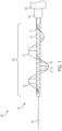
- the treatment devices disclosed herein can be provided as one part of a treatment system, which includes: a treatment device 101, a covering sheath 103, an elongated delivery sheath 105, which may have an expandable braided tip 106 that can expand to accommodate a clot in the process of retrieval, and an atraumatic steerable guidewire 107.
- the covering sheath 103 is slidably received within a lumen of the delivery sheath 105.
- the treatment device can be slidably received within the lumen of the covering sheath, and a guidewire 107 can be slidably received within a lumen of the treatment device.
- the delivery sheath 105 can have a nominal diameter of approximately 12-14 Fr, and the covering sheath 103 can have a nominal diameter of between about 6-9 Fr, or approximately 8 Fr.
- the delivery sheath 105 can have an expandable tip 106 (e.g., a 2 cm braided tip) at its distal portion, for example a braid or a balloon that can be expanded into apposition against a surrounding vessel wall.
- the covering sheath 103 can have an expandable tip (e.g., a 2 cm braided tip) disposed at its distal portion.
- the bodies of the delivery sheath 105 and/or the covering sheath 103 can be made from various thermoplastics, e.g., polytetrafluoroethylene (PTFE or TEFLON ® ), fluorinated ethylene propylene (FEP), high-density polyethylene (HDPE), polyether ether ketone (PEEK), Polyether block amide (PEBAX), etc., which can optionally be lined on the inner surface or an adjacent surface with a hydrophilic material such as polyvinylpyrrolidone (PVP) or some other plastic coating. Additionally, either surface can be coated with various combinations of different materials, depending upon the desired results.
- PTFE or TEFLON ® polytetrafluoroethylene
- FEP fluorinated ethylene propylene
- HDPE high-density polyethylene
- PEEK polyether ether ketone
- PEBAX Polyether block amide
- Figure 1 illustrates a treatment system 100, which includes a treatment device 101 slidably received within a surrounding covering sheath 103 and a larger-diameter delivery sheath 105.
- the covering sheath 103 can have a diameter of between about 6-9 Fr, or approximately 8 Fr. This would be used to deliver the treatment device 101 through the clot, as described in more detail below.
- the covering sheath 103 may remain proximal to the functional section of the treatment device 101 as tension is applied to the shaft of the treatment device 101 to draw the clot into the larger-diameter delivery sheath 105.
- the delivery sheath 105 can have a diameter of approximately 12-14 Fr in some embodiments, and may optionally include an expandable tip 106 (e.g., a 2 cm braided tip) capable of further capturing and compressing the clot to allow for seamless extraction.
- an expandable tip 106 e.g., a 2 cm braided tip
- a treatment device 101 (e.g., a treatment catheter) can include an elongated tubular shaft having a distally located functional portion 109.
- the treatment device 101 can be slidably advanced over a guidewire, and can also be slidably received within a surrounding covering sheath 103 and/or delivery sheath 105 for advancement to a treatment site.
- the functional portion 109 of the treatment device 101 can be restrained in a compressed, unexpanded, linearized, and/or low-profile configuration.
- the functional portion 109 of the treatment device 101 can assume an uncompressed, expanded, deployed, and/or helical configuration having a greater radially outermost dimension than in the compressed state.
- the functional portion 109 of the treatment device 101 can include one or more helically extending elements separated transversely by a flexible material such as a polyurethane sheet.
- the flexible material may be substantially continuous or can include one or more apertures along its length.
- the helically extending elements together may cause the functional portion 109 of the treatment device 101 to tend towards a pre-formed, generally spiral or helical shape.
- the functional portion 109 of the treatment device 101 is transformable between a delivery state having a low profile that is configured to pass through the vasculature and a deployed state having a radially expanded shape (e.g., generally spiral/helical or coil shape) in which the helically extending elements maintain the assembly in stable apposition with an inner wall of the target blood vessel.
- a radially expanded shape e.g., generally spiral/helical or coil shape
- the functional portion 109 of the treatment device 101 includes a coiled inner member 111 spirally wound around a central core member 115.
- a helical outer member 113 spirally winds around and surrounds the coiled inner member 111 and the central tubular member.
- the coiled inner member 111 and/or the helical outer member 113 can be made of nitinol, stainless steel, rigid polymers, or other suitable material.
- the diameter of the helical outer member 113 in the expanded state is approximately the same as the diameter of the vein or vessel at the treatment site.
- the helical outer member 113 has a diameter in the expanded, unconstrained state of around 12-14 mm, but may also function if constrained by smaller diameter vessels or due to engagement with clot material. Alternatively, the helical outer member 113 can be provided in different sizes for different target vessels.
- the helical outer member 113 and the coiled inner member 111 can be bonded together at the proximal and distal ends of the functional portion 109 of the device.
- the core member 115 can be an elastic polymer tube having a lumen that allows passage over a guidewire (e.g., over a minimum a 0.035" guidewire).
- the helical outer member 113 can have a significantly greater pitch than the more tightly wound coiled inner member 111.
- the coiled inner member 111 can be configured such that extension and contraction of the coiled inner member 111 does not substantially alter a radial dimension of the coiled inner member 111.
- the helical outer member 113 can be configured such that, when elongated, the helical outer member 113 assumes a reduced radial dimension, for example fully or partially linearizing such that the outer member 113 runs substantially parallel to the core member 115.
- the helical outer member 113 When the helical outer member 113 is compressed or is released from elongation, it may assume a deployed configuration with an increased radial dimension as shown in Figure 1 .
- the length of the functional portion 109 is approximately 80 mm when unconstrained in the expanded, deployed configuration.
- the helical outer member 113 and the coiled inner member 111 may increase in length by between 50-100% of the unconstrained length.
- a sheet 117 of flexible material is coupled to both the coiled inner member 111 and the helical outer member 113 of the treatment device 101.
- the sheet 117 can be made of a polymer, for example urethane, polyethylene, expanded polytetrafluoroethylene (EPTFE), polyethylene terephthalalate (PET), or other biocompatible polymer. It may also be made of a flexible metal mesh or screen, such as a fine nitinol or stainless steel mesh.
- the sheet 117 can be attached to the helical outer member 113 while it is in an extended (e.g., linearized) state, such that when the helical outer member 113 assumes a helical or spiral configuration (such as during device deployment), the sheet 117 also forms a spiral helical strip.
- the sheet may have one or more apertures 119 (e.g., pores, perforations, slices, segments, twists, cups, or other features) along its length to allow it to engage the clot when it is deployed.
- the apertures may fully separate adjacent portions of the sheet 117 such that the sheet 117 includes multiple discrete sections extending between the inner member 111 and the outer member 113.
- the remaining material defined by the apertures 119 can form baffles 121 configured to engage clot material.
- a distal portion of the sheet has no apertures, thereby forming a closed-cell filter 123.
- This filter 123 can prevent distal embolization of clot material to more central veins, main pulmonary arteries, or sub-segmental pulmonary arteries.
- the treatment device 101 may be used in conjunction with intravenous or intra-arterial thrombolytic medication, while in other embodiments the treatment device 101 is configured to perform mechanical thrombectomy without the need for adjunctive care.
- a mechanism at the proximal end of the treatment device 101 may be provided to automate the deployment of the treatment device 101 to allow for a staged-ratio deployment, such that, for example, for every one centimeter of covering sheath 103 withdrawal, three centimeters of the treatment device 101 are exposed. This may optimize the radial expansion of the helical outer member 113 to ensure maximum contact with the vessel wall at the location of the thrombus, and thus maximum clot retrieval per treatment iteration.
- baffles 121 formed in the sheet 117 can be bolstered or manufactured with smaller radially directed nitinol wires that would allow for maximum envelopment of the central blood clot. This could in turn maximize clot compression for final extraction.
- a plastic coating to the helical outer member 113 can act as an outer soft protecting edge to protect the vessel wall, with an inner cutting edge such that if the device 101 is rotated it can separate the chronic fibrin from the vessel wall to facilitate clot retrieval.
- An alternative embodiment of the treatment device 101 may obviate the polymer baffles 121, using a simple helical outer member 113, affixed proximally and distally to a central guidewire or other centrally disposed anchoring member.
- an open-cell or closed-cell embolic protection cap may optionally be positioned at the distal-most aspect of the device 101.
- the coiled inner member 111 can be omitted or replaced with another suitable inner anchor configured to couple to the sheet of flexible material 117.
- the coiled inner member 111 could be replaced with a hypotube, with a series of discrete tubular elements or rings, or other elements mounted over the core member with some degree of freedom.
- the dimensions described herein relate to a device for removing clot from leg veins or pulmonary arteries. However, these dimensions could all be changed to make devices of other sizes to treat other vessels. For example, instead of an 0.035" guidewire, the device could be designed for delivery over an 0.018", 0.014", or even a 0.010" guidewire.
- Figure 2 illustrates clot material CM that is enveloped by the helical outer member 113 and baffles 121 that have been pulled proximally to help compress the clot material CM.
- the clot material CM is protected from distal embolization by the protective distal filter 123 and proximally is beginning to be compressed by the outer-most delivery sheath 105 in preparation for removal.
- the clot material CM may also be substantially elongated by the linearization of the helical outer member 113 and stretching of the coiled inner member 111 as it is withdrawn, which may substantially reduce the overall diameter of the clot material CM, allowing it to be more effectively drawn into the covering sheath 103 and/or the delivery sheath 105.
- the helical outer member As the helical outer member is linearized, the helical outer member and the coiled are pulled together into close apposition.
- the linear sheet of material whose edges are formed by the helical outer member and coiled inner member, thereby forms a relatively closed tubular pouch, which serves to enclose and retain the clot material CM as it is withdrawn from the vessel.
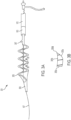
- Figure 3A illustrates an alternate embodiment of a treatment device 301 configured for removal of chronic fibrin-laden clots.
- the treatment device 301 includes an integrally formed embolic protection filter or umbrella 303 at the distal end of the device 301.
- the helical outer member 305 can be similar to the helical outer member 113 described above, except the helical outer member 305 illustrated in Figure 3A is coated in a durable polymer.
- the helical outer member 305 can have a smooth, curved radially outer surface 305a configured to abut the vessel wall and a less curved inner surface 305b, thereby providing a leading edge 305c and a trailing edge 305d at the junctions of the two surfaces which can help separate chronic clot from the wall of the vessel.
- the helical outer member 305 can include only one of the edges 305c or 305d along some or all of its length.
- the radially inward facing surface 305b is not planar but has some curvature, yet still provides a cutting edge 305c and/or 305d where the inward facing surface 305b joins the curved outer surface 305a.
- the helical outer member 305 can include a ridge, protrusion, or other projecting element that forms a cutting member or cutting edge.
- Such a cutting edge can be particularly useful in separating a chronic fibrin clot from a vessel wall, for example allowing the device to be used for an endovenectomy.
- the helical outer member 305 can be urged forward and/or backward once in the expanded state such that the cutting edge is advanced axially into clot material.
- the cutting edge may face only in one axial direction - e.g., only distally facing or only proximally facing at any point along the helical outer member 305 or along all of the helical outer member 305.
- the outer helical member 305 can have one cutting edge facing distally and another cutting edge facing proximally, such that both proximal and distal movement of the helical outer member 305 enables the cutting edge to contact clot material.
- a unidirectional strut 307 which may be oriented proximally that is configured to open on removal of the covering sheath 103. This strut 307 may help to release the chronic clot from the wall and act as a "backstop" for the clot when the covering sheath 103 is being advanced prior to clot retrieval.
- FIG. 4 illustrates the proximal portion of the treatment system 100.
- a proximal portion of the treatment device 101 can extend proximally beyond proximal ends of the delivery sheath 105 and treatment catheter, allowing a clinician to manipulate the proximal end of the treatment system 100.
- a torque device 401 can engage the proximal portion of treatment device 101 to allow for some rotation of the device within the vessel to help orient the helical outer member 113 along the outer edge of the vessel and ensure maximum clot retrieval.
- the torque device 401 can be permanently coupled to the proximal portion of the treatment device 101, while in other embodiments the torque device is removable.
- the proximal portion of the treatment system 100 can include a first hub 403 and a second hub 405 configured to be positioned external to the patient.
- the first and/or second hubs can be coupled to the delivery sheath 105 and/or the covering sheath 103, and can include a hemostatic adaptor, a Tuohy Borst adaptor, and/or other suitable valves and/or sealing devices.
- the first and/or second hubs can further include an aspiration line coupled to a negative pressure-generating device, such as a syringe or a vacuum pump.
- the first and/or second hubs can include a port configured to receive one or more fluids before, during, and/or after the procedure (e.g., contrast, saline, etc.).
- the treatment device 101 Prior to delivery, the treatment device 101 can be withdrawn into the covering sheath 103 for initial delivery into the vessel. This linearizes the helical outer member 113 such that it assumes the low-profile, compressed configuration. For a helix which has a pitch approximately equal to its diameter, this helix may elongate by over three times its length when it is linearized. When the helix is linearized in the covering sheath 103, the coiled inner member 111 can stretch by an equivalent length.
- a procedure for using the treatment device can be as follows. First, the larger-diameter delivery sheath 105 is introduced into the vein or vessel. Then the treatment device 101 contained within the covering sheath 103 is introduced through the clot over a central guidewire.
- the helical outer member 113 and/or the inner member 111 can include radiopaque markers or can be formed at least partially of radiopaque material to facilitate visualization under fluoroscopy. Once the distal end of the covering sheath 103 is past the clot, the covering sheath 103 is gradually withdrawn, allowing the helical outer member 113 to expand into the clot.
- the handle at the proximal end of the treatment device 101 may have a mechanism which simultaneously advances the treatment device 101 while retracting the covering sheath 103.
- the treatment device may be configured to expand within the blood clot and into apposition with the vessel wall. Once deployed, a slight twisting motion or advancement or retraction may allow for more complete deployment of the treatment device 101 with the outer edge of the polymer-wrapped helical outer member 113 abutting the vein wall throughout the length of the clot.
- the clot may be cut into a spiral shape by the expansion of the helical outer member 113, and since the strip of flexible material 117 extends from the helical outer member 113 to the coiled inner member 111, the clot will be engaged by this strip of flexible material 117.
- Retrieval may then begin by pulling back proximally on the treatment device.
- the covering sheath 103 would move back with it, leaving the functional portion 109 of the treatment device out of the covering sheath 103.
- This retraction could be done manually or via a retraction handle at the hub of the catheter that would allow for precise tension on the helical outer member 113.
- the covering sheath 103 and/or the delivery sheath 105 may be advanced distally over the treatment device 101 to recapture or resheath the treatment device 101.
- the helical outer member 113 and coiled inner member 111 are retracted into the larger delivery sheath 105, they will both lengthen and partially linearize as they are stretched. This will also begin to cause the helical outer member 113 to pull away from the vessel wall and draw closer to the coiled inner member 111.
- the baffles 121 in the flexible material 117 between the coiled inner member 111 and the helical outer member 113 would then tend to engage the blood clot and begin to linearize the spiral clot to facilitate retrieval.
- the treatment device may then be slowly withdrawn into the larger delivery sheath 105.
- the helical outer member 113, the polymer baffles 121, and the closed-cell polymer embolic-protection filter 123 each facilitate drawing the clot into the delivery sheath 105.
- the delivery sheath 105 could alternatively be advanced forward as the clot is captured, such that the expanding tip could help to further capture and compress the retrieved clot.
- the treatment device 101 and covering sheath 103 could then be completely withdrawn through the delivery sheath 105, or both the covering sheath 103 and the delivery sheath 105 with the treatment device 101 could then be removed through a larger access sheath over a wire, thus completing clot retrieval.
- the device could be cleaned and re-housed to allow for multiple treatment passes to be made.
- Figure 5 illustrates a manufacturing process for the functional section 109 of the treatment device.
- a helical outer member 113 e.g., a wire or other elongated structure
- a coiled inner member 111 at its proximal and distal end portions, for example via soldering, welding, adhesives, or other suitable fixation technique.
- this assembly can be twisted and pulled lengthwise to unwind the helix and straighten it, and the straightened helix is held in a fixture parallel to and an appropriate distance away from the coiled inner member 111, as depicted in Figure 5 .
- a polymer tube may then be run through the lumen of the coiled inner member 111.
- a Teflon blocker tube may be inserted into the center lumen of this polymer tube to ensure an inner guidewire lumen diameter of at least approximately 0.040" to facilitate passage of an 0.035" or 0.038" guidewire.
- a sheet of flexible material 117 can then be wrapped around the helical outer member 113 and the coiled inner member 111 and sealed in place.
- the sheet 117 may be fused to itself as well as to the core member 115 to hold the assembly together. After the sheet 117 is fused, it can be trimmed and any desired slotting, baffling, twisting, cupping, perforating, or other processing of the polymer sheet can be performed to optimize its clot-engagement capabilities.
- this assembly When this assembly is released from the fixture, it returns to its helical shape around the coiled inner member 111, which forms a shape suitable for clot retrieval as described above.
- the distal aspect of the polymer may remain in a closed-cell fashion without baffles to provide a distal embolic filter 123.
- the proximal end of the assembly may then be attached to the shaft of the treatment device 101, for example by inserting and bonding the proximal extension of the coiled inner member 111 and/or the helical outer member 113 into the shaft of the treatment device 101.
- oval windows 119 seen in Figure 5 are examples of cut windows that allow for the remaining polyurethane "bridges" to act as baffles 121 that can engage and compress a clot when tension is pulled on the proximal end of the treatment device, straightening the helical outer member 113 and stretching the coiled inner member 111.
- Various other patterns of cuts, perforations, slices, or other openings can be provided to tailor performance of the remaining flexible material 117 in engaging clot material.
Landscapes
- Health & Medical Sciences (AREA)
- Surgery (AREA)
- Life Sciences & Earth Sciences (AREA)
- Heart & Thoracic Surgery (AREA)
- Nuclear Medicine, Radiotherapy & Molecular Imaging (AREA)
- Vascular Medicine (AREA)
- Engineering & Computer Science (AREA)
- Biomedical Technology (AREA)
- Orthopedic Medicine & Surgery (AREA)
- Medical Informatics (AREA)
- Molecular Biology (AREA)
- Animal Behavior & Ethology (AREA)
- General Health & Medical Sciences (AREA)
- Public Health (AREA)
- Veterinary Medicine (AREA)
- Surgical Instruments (AREA)
Applications Claiming Priority (3)
| Application Number | Priority Date | Filing Date | Title |
|---|---|---|---|
| US201862717077P | 2018-08-10 | 2018-08-10 | |
| EP19759191.0A EP3833278B1 (de) | 2018-08-10 | 2019-08-09 | Vorrichtung für mechanische venengerinnselbergung |
| PCT/US2019/045941 WO2020033853A1 (en) | 2018-08-10 | 2019-08-09 | Mechanical venous clot retrieval |
Related Parent Applications (1)
| Application Number | Title | Priority Date | Filing Date |
|---|---|---|---|
| EP19759191.0A Division EP3833278B1 (de) | 2018-08-10 | 2019-08-09 | Vorrichtung für mechanische venengerinnselbergung |
Publications (2)
| Publication Number | Publication Date |
|---|---|
| EP4454574A2 true EP4454574A2 (de) | 2024-10-30 |
| EP4454574A3 EP4454574A3 (de) | 2024-12-25 |
Family
ID=67766356
Family Applications (2)
| Application Number | Title | Priority Date | Filing Date |
|---|---|---|---|
| EP24199032.4A Pending EP4454574A3 (de) | 2018-08-10 | 2019-08-09 | Vorrichtung für mechanische venengerinnselbergung |
| EP19759191.0A Active EP3833278B1 (de) | 2018-08-10 | 2019-08-09 | Vorrichtung für mechanische venengerinnselbergung |
Family Applications After (1)
| Application Number | Title | Priority Date | Filing Date |
|---|---|---|---|
| EP19759191.0A Active EP3833278B1 (de) | 2018-08-10 | 2019-08-09 | Vorrichtung für mechanische venengerinnselbergung |
Country Status (5)
| Country | Link |
|---|---|
| US (2) | US12364495B2 (de) |
| EP (2) | EP4454574A3 (de) |
| JP (2) | JP7470117B2 (de) |
| CN (2) | CN119112290A (de) |
| WO (1) | WO2020033853A1 (de) |
Families Citing this family (9)
| Publication number | Priority date | Publication date | Assignee | Title |
|---|---|---|---|---|
| US11471582B2 (en) | 2018-07-06 | 2022-10-18 | Incept, Llc | Vacuum transfer tool for extendable catheter |
| US11633272B2 (en) | 2019-12-18 | 2023-04-25 | Imperative Care, Inc. | Manually rotatable thrombus engagement tool |
| US12433735B2 (en) | 2021-03-10 | 2025-10-07 | Intervene, Inc. | Interventional systems and associated devices and methods |
| US12376928B2 (en) | 2021-08-12 | 2025-08-05 | Imperative Care, Inc. | Catheter drive system for supra-aortic access |
| USD1077996S1 (en) | 2021-10-18 | 2025-06-03 | Imperative Care, Inc. | Inline fluid filter |
| EP4489666A1 (de) * | 2022-03-10 | 2025-01-15 | Intervene, Inc. | Interventionelle systeme sowie zugehörige vorrichtungen und verfahren |
| US12484918B2 (en) * | 2023-06-02 | 2025-12-02 | Translational And Fundamental Technologies Institute Llc | Thrombectomy device and methods of use thereof |
| CN117137575B (zh) * | 2023-09-06 | 2024-06-25 | 上海心玮医疗科技股份有限公司 | 一种带有切栓功能的可扩口抽吸导管 |
| US12226112B1 (en) | 2023-12-15 | 2025-02-18 | Cerebrova KP Medical, Inc. | Neurovascular clot retrieving system |
Family Cites Families (31)
| Publication number | Priority date | Publication date | Assignee | Title |
|---|---|---|---|---|
| US5192286A (en) * | 1991-07-26 | 1993-03-09 | Regents Of The University Of California | Method and device for retrieving materials from body lumens |
| US5972019A (en) * | 1996-07-25 | 1999-10-26 | Target Therapeutics, Inc. | Mechanical clot treatment device |
| US5882329A (en) | 1997-02-12 | 1999-03-16 | Prolifix Medical, Inc. | Apparatus and method for removing stenotic material from stents |
| US20010031981A1 (en) * | 2000-03-31 | 2001-10-18 | Evans Michael A. | Method and device for locating guidewire and treating chronic total occlusions |
| ATE519437T1 (de) | 2001-01-09 | 2011-08-15 | Microvention Inc | Embolektomie-katheter |
| US6635070B2 (en) * | 2001-05-21 | 2003-10-21 | Bacchus Vascular, Inc. | Apparatus and methods for capturing particulate material within blood vessels |
| US7344549B2 (en) * | 2002-01-31 | 2008-03-18 | Advanced Cardiovascular Systems, Inc. | Expandable cages for embolic filtering devices |
| US20040088000A1 (en) * | 2002-10-31 | 2004-05-06 | Muller Paul F. | Single-wire expandable cages for embolic filtering devices |
| US20050283166A1 (en) * | 2004-06-17 | 2005-12-22 | Secant Medical, Llc | Expandible snare |
| IL169696A (en) | 2004-07-22 | 2014-12-31 | Cordis Corp | A device for filtering blood in a vessel with helical elements |
| US20060184194A1 (en) * | 2005-02-15 | 2006-08-17 | Cook Incorporated | Embolic protection device |
| CA2604081C (en) * | 2005-05-25 | 2013-11-26 | Chestnut Medical Technologies, Inc. | System and method for delivering and deploying a self-expanding device within a vessel |
| US20090105687A1 (en) * | 2007-10-05 | 2009-04-23 | Angioscore, Inc. | Scoring catheter with drug delivery membrane |
| US20090240238A1 (en) | 2008-03-24 | 2009-09-24 | Medtronic Vascular, Inc. | Clot Retrieval Mechanism |
| US8945160B2 (en) * | 2008-07-03 | 2015-02-03 | Hotspur Technologies, Inc. | Apparatus and methods for treating obstructions within body lumens |
| AU2009266808B2 (en) | 2008-07-03 | 2014-07-10 | Teleflex Life Sciences Limited | Apparatus and methods for treating obstructions within body lumens |
| CN102665815B (zh) * | 2009-07-23 | 2015-03-18 | 浩特斯博尔技术公司 | 用于处理体腔内阻塞的装置 |
| US9561094B2 (en) | 2010-07-23 | 2017-02-07 | Nfinium Vascular Technologies, Llc | Devices and methods for treating venous diseases |
| CN103200886B (zh) | 2010-10-28 | 2015-07-29 | 科维蒂恩有限合伙公司 | 物质移除装置和使用方法 |
| AU2012338476A1 (en) | 2011-10-24 | 2014-05-08 | Rapid Medical Ltd. | Clot removal devices and methods |
| US9204887B2 (en) * | 2012-08-14 | 2015-12-08 | W. L. Gore & Associates, Inc. | Devices and systems for thrombus treatment |
| BR112015020071B1 (pt) | 2013-02-22 | 2022-09-13 | NeuroVasc Technologies, Inc | Dispositivo de trombectomia |
| US20140276403A1 (en) * | 2013-03-13 | 2014-09-18 | DePuy Synthes Products, LLC | Ischemic stroke device |
| ES2960917T3 (es) | 2013-03-14 | 2024-03-07 | Neuravi Ltd | Dispositivo de recuperación de coágulos para eliminar coágulos oclusivos de un vaso sanguíneo |
| JP6435280B2 (ja) | 2013-03-15 | 2018-12-05 | ナショナル ユニバーシティー オブ アイルランド, ゴールウェイ | 内腔内部および体内腔の壁から物質を除去するのに適したデバイス |
| ES2742852T3 (es) | 2013-05-02 | 2020-02-17 | Veryan Medical Ltd | Balón expansible |
| US10231751B2 (en) * | 2013-05-29 | 2019-03-19 | Thomas A. Sos | Thrombus removal and intravascular distal embolic protection device |
| GB201410008D0 (en) | 2014-06-05 | 2014-07-16 | British American Tobacco Co | Tipping paper feed assembly for use in smoking article manufacture |
| US10980555B2 (en) | 2016-07-12 | 2021-04-20 | Cardioprolific Inc. | Methods and devices for clots and tissue removal |
| JP7086935B2 (ja) | 2016-08-17 | 2022-06-20 | ニューラヴィ・リミテッド | 血管から閉塞性血栓を除去するための血栓回収システム |
| US11877752B2 (en) * | 2016-09-07 | 2024-01-23 | Daniel Ezra Walzman | Filterless aspiration, irrigating, macerating, rotating microcatheter and method of use |
-
2019
- 2019-08-09 EP EP24199032.4A patent/EP4454574A3/de active Pending
- 2019-08-09 CN CN202411219465.6A patent/CN119112290A/zh active Pending
- 2019-08-09 EP EP19759191.0A patent/EP3833278B1/de active Active
- 2019-08-09 US US17/250,606 patent/US12364495B2/en active Active
- 2019-08-09 JP JP2021531613A patent/JP7470117B2/ja active Active
- 2019-08-09 CN CN201980053007.0A patent/CN112752548B/zh active Active
- 2019-08-09 WO PCT/US2019/045941 patent/WO2020033853A1/en not_active Ceased
-
2024
- 2024-04-05 JP JP2024061321A patent/JP2024083473A/ja active Pending
-
2025
- 2025-07-18 US US19/274,341 patent/US20250345081A1/en active Pending
Also Published As
| Publication number | Publication date |
|---|---|
| CN119112290A (zh) | 2024-12-13 |
| US20210307767A1 (en) | 2021-10-07 |
| WO2020033853A1 (en) | 2020-02-13 |
| EP3833278A1 (de) | 2021-06-16 |
| JP7470117B2 (ja) | 2024-04-17 |
| CN112752548B (zh) | 2024-09-17 |
| CN112752548A (zh) | 2021-05-04 |
| EP3833278B1 (de) | 2024-09-11 |
| JP2024083473A (ja) | 2024-06-21 |
| EP4454574A3 (de) | 2024-12-25 |
| US20250345081A1 (en) | 2025-11-13 |
| US12364495B2 (en) | 2025-07-22 |
| JP2021533959A (ja) | 2021-12-09 |
Similar Documents
| Publication | Publication Date | Title |
|---|---|---|
| US20250345081A1 (en) | Mechanical venous clot retrieval | |
| JP7389159B2 (ja) | 血管から閉塞性血餅を除去するための血餅回収デバイス | |
| US10792055B2 (en) | Clot removal device | |
| US9259237B2 (en) | Methods and apparatus for treating pulmonary embolism | |
| KR20220034005A (ko) | 확장형 입구 카테터 | |
| US20150374391A1 (en) | Methods and apparatus for treating small vessel thromboembolisms | |
| CN111246811A (zh) | 治疗血管闭塞的装置及方法 | |
| CN113813012A (zh) | 双通道血栓切除装置 | |
| EP4648713A1 (de) | Katheter zur verwendung mit gerinnselbehandlungssystemen | |
| US12290278B2 (en) | Interventional systems and associated devices and methods | |
| US20250017618A1 (en) | Mechanical thrombectomy assembly with embolic protection, and associated devices, systems, and methods | |
| US12390237B2 (en) | Neurovascular clot retrieving system | |
| US12496081B2 (en) | Catheter for use with clot treatment systems | |
| US20250331874A1 (en) | Systems and methods for restoring blood vessel patency |
Legal Events
| Date | Code | Title | Description |
|---|---|---|---|
| PUAI | Public reference made under article 153(3) epc to a published international application that has entered the european phase |
Free format text: ORIGINAL CODE: 0009012 |
|
| STAA | Information on the status of an ep patent application or granted ep patent |
Free format text: STATUS: THE APPLICATION HAS BEEN PUBLISHED |
|
| AC | Divisional application: reference to earlier application |
Ref document number: 3833278 Country of ref document: EP Kind code of ref document: P |
|
| AK | Designated contracting states |
Kind code of ref document: A2 Designated state(s): AL AT BE BG CH CY CZ DE DK EE ES FI FR GB GR HR HU IE IS IT LI LT LU LV MC MK MT NL NO PL PT RO RS SE SI SK SM TR |
|
| REG | Reference to a national code |
Ref country code: DE Ref legal event code: R079 Free format text: PREVIOUS MAIN CLASS: A61B0017220000 Ipc: A61B0017221000 |
|
| PUAL | Search report despatched |
Free format text: ORIGINAL CODE: 0009013 |
|
| AK | Designated contracting states |
Kind code of ref document: A3 Designated state(s): AL AT BE BG CH CY CZ DE DK EE ES FI FR GB GR HR HU IE IS IT LI LT LU LV MC MK MT NL NO PL PT RO RS SE SI SK SM TR |
|
| RIC1 | Information provided on ipc code assigned before grant |
Ipc: A61B 17/3207 20060101ALN20241115BHEP Ipc: A61B 17/221 20060101AFI20241115BHEP |
|
| STAA | Information on the status of an ep patent application or granted ep patent |
Free format text: STATUS: REQUEST FOR EXAMINATION WAS MADE |
|
| 17P | Request for examination filed |
Effective date: 20250624 |
|
| STAA | Information on the status of an ep patent application or granted ep patent |
Free format text: STATUS: EXAMINATION IS IN PROGRESS |
|
| 17Q | First examination report despatched |
Effective date: 20251021 |