EP4454450A1 - Arbeitsmaschine mit stange und hänger für schultergurt - Google Patents
Arbeitsmaschine mit stange und hänger für schultergurt Download PDFInfo
- Publication number
- EP4454450A1 EP4454450A1 EP24172433.5A EP24172433A EP4454450A1 EP 4454450 A1 EP4454450 A1 EP 4454450A1 EP 24172433 A EP24172433 A EP 24172433A EP 4454450 A1 EP4454450 A1 EP 4454450A1
- Authority
- EP
- European Patent Office
- Prior art keywords
- operating rod
- operating
- operating lever
- hanging tool
- stopper
- Prior art date
- Legal status (The legal status is an assumption and is not a legal conclusion. Google has not performed a legal analysis and makes no representation as to the accuracy of the status listed.)
- Pending
Links
Images


Classifications
-
- A—HUMAN NECESSITIES
- A01—AGRICULTURE; FORESTRY; ANIMAL HUSBANDRY; HUNTING; TRAPPING; FISHING
- A01D—HARVESTING; MOWING
- A01D34/00—Mowers; Mowing apparatus of harvesters
- A01D34/835—Mowers; Mowing apparatus of harvesters specially adapted for particular purposes
- A01D34/90—Mowers; Mowing apparatus of harvesters specially adapted for particular purposes for carrying by the operator
- A01D34/902—Ergonomic provisions
-
- A—HUMAN NECESSITIES
- A01—AGRICULTURE; FORESTRY; ANIMAL HUSBANDRY; HUNTING; TRAPPING; FISHING
- A01D—HARVESTING; MOWING
- A01D34/00—Mowers; Mowing apparatus of harvesters
- A01D34/835—Mowers; Mowing apparatus of harvesters specially adapted for particular purposes
- A01D34/84—Mowers; Mowing apparatus of harvesters specially adapted for particular purposes for edges of lawns or fields, e.g. for mowing close to trees or walls
-
- F—MECHANICAL ENGINEERING; LIGHTING; HEATING; WEAPONS; BLASTING
- F16—ENGINEERING ELEMENTS AND UNITS; GENERAL MEASURES FOR PRODUCING AND MAINTAINING EFFECTIVE FUNCTIONING OF MACHINES OR INSTALLATIONS; THERMAL INSULATION IN GENERAL
- F16M—FRAMES, CASINGS OR BEDS OF ENGINES, MACHINES OR APPARATUS, NOT SPECIFIC TO ENGINES, MACHINES OR APPARATUS PROVIDED FOR ELSEWHERE; STANDS; SUPPORTS
- F16M13/00—Other supports for positioning apparatus or articles; Means for steadying hand-held apparatus or articles
- F16M13/04—Other supports for positioning apparatus or articles; Means for steadying hand-held apparatus or articles for supporting on, or holding steady relative to, a person, e.g. by chains, e.g. rifle butt or pistol grip supports, supports attached to the chest or head
-
- A—HUMAN NECESSITIES
- A01—AGRICULTURE; FORESTRY; ANIMAL HUSBANDRY; HUNTING; TRAPPING; FISHING
- A01D—HARVESTING; MOWING
- A01D34/00—Mowers; Mowing apparatus of harvesters
- A01D34/01—Mowers; Mowing apparatus of harvesters characterised by features relating to the type of cutting apparatus
- A01D34/412—Mowers; Mowing apparatus of harvesters characterised by features relating to the type of cutting apparatus having rotating cutters
- A01D34/416—Flexible line cutters
-
- F—MECHANICAL ENGINEERING; LIGHTING; HEATING; WEAPONS; BLASTING
- F16—ENGINEERING ELEMENTS AND UNITS; GENERAL MEASURES FOR PRODUCING AND MAINTAINING EFFECTIVE FUNCTIONING OF MACHINES OR INSTALLATIONS; THERMAL INSULATION IN GENERAL
- F16B—DEVICES FOR FASTENING OR SECURING CONSTRUCTIONAL ELEMENTS OR MACHINE PARTS TOGETHER, e.g. NAILS, BOLTS, CIRCLIPS, CLAMPS, CLIPS OR WEDGES; JOINTS OR JOINTING
- F16B7/00—Connections of rods or tubes, e.g. of non-circular section, mutually, including resilient connections
- F16B7/10—Telescoping systems
- F16B7/14—Telescoping systems locking in intermediate non-discrete positions
- F16B7/1418—Telescoping systems locking in intermediate non-discrete positions with a clamping collar or two split clamping rings tightened by a screw or a cammed latch member
Definitions
- the present invention relates to a working machine with an operating rod, and a hanging tool for a shoulder belt of the working machine.
- a working machine such as a brush cutter for mowing work on the ground and a hedge trimmer for pruning tall tree branches is equipped with a long operating rod.
- a working device is mounted on the head end of the operating rod, and a power device such as an engine and an electric motor is mounted on the base end of the operating rod.
- the operating rod of this working machine serves as a coupling rod to connect the power device and the working device, and it includes a power transmission mechanism and wires arranged therein.
- a handle is provided on the operating rod. To perform work, a standing worker moves the working rod gently from one side to another side while gripping the handle to touch the working device mounted on the head end of the operating rod to objects.
- a working machine with the above-described operating rod provided with a hanging tool for a shoulder belt.
- the shoulder belt is used to reduce the burden of the hand and the arm of the worker gripping the handle by bearing the weight of the working machine with the operating rod on the shoulder of the worker.
- a hanging tool for a shoulder belt including a stopper. A part of the stopper is divided in the circumferential direction of the operating rod, and a screw is inserted into the divided positions and fastened to secure the operating rod (see Japanese Patent Application Laid-Open No. 2000-316349 ).
- the position of the hanging tool for a shoulder belt mounted to the operating rod is set in consideration of the weight balance between the working device on the head end of the operating rod and the power device on the base end of the operating rod.
- the working device on the head end of the operating rod is often replaced with a different device having a different weight, for example, a disc-like cutting blade and a resin string.
- the weight of the power device on the base end of the operating rod may vary depending on the amount of fuel and the mounting state of a battery.
- the mounting position of the hanging tool for a shoulder belt is required to be changed as appropriate according to a change in the weight balance between the head end and the base end of the operating rod.
- the mounting position of the hanging tool for a shoulder belt may also be required to be changed according to the height of the worker using the working machine.
- the hanging tool including the stopper fastened with the screw needs complicated operation to loosen the screw in order to change the position of the stopper. Therefore, there is a problem that the position of the hanging tool for a shoulder belt cannot be speedily and easily changed.
- the present invention is proposed to address the problem. Therefore, the objects of the invention are to make it possible to speedily and easily change the position of the hanging tool for a shoulder belt according to the weight balance between the head end and the base end of the operating rod, to prevent the hanging tool for a shoulder belt from being released by unintended operation of the worker, and to hang the operating rod from the shoulder belt in an appropriate position.
- the present invention provides a working machine with an operating rod configured to perform work while a handle provided on the operating rod is gripped.
- the working machine includes a working device mounted on the head end of the operating rod, a power device mounted on the base end of the operating rod, and the operating rod equipped with a hanging tool for a shoulder belt.
- the hanging tool includes a hanging tool body.
- the hanging tool body includes a connection hole to connect to the shoulder belt, and it is configured to be able to slide in a longitudinal direction of the operating rod while surrounding the operating rod.
- the hanging tool also includes a stopper coupled to the hanging tool body.
- the stopper includes a pair of fastening portions facing one another: they are configured to be able to move toward one another or move away from one another while securing the operating rod.
- the fastening portions include through holes orthogonal to the longitudinal direction of the operating rod.
- a first end of an operating shaft inserted into the through holes is retained not to fall off, and a second end is coupled to an operating lever.
- the base end of the operating lever is pivotally supported around a rotating shaft parallel to the operating rod on the second end side of the operating shaft.
- the operating lever is rotated such that the head end of the operating lever moves toward a side surface of the operating rod to fasten the stopper.
- the operating lever is rotated such that the head end of the operating lever moves away from the side surface of the operating rod to unfasten the stopper.
- the invention having the above-described features, it is possible to change the position of the hanging tool for a shoulder belt speedily and easily according to the weight balance between the head end and the base end of the operating rod of the working machine. In addition, it is possible to prevent the hanging tool for a shoulder belt from being released by unintended operation, and hang the operating rod from the shoulder belt in an appropriate position.
- a working machine with an operating rod (hereinafter, referred to as "working machine") 1 includes an operating rod 2.
- a working device 3 is mounted on the head end of the operating rod 2
- a power device 4 is mounted on the base end of the operating rod 2.
- a worker M performs work with the working machine 1gripping a handle 5 provided on the operating rod 2.
- the working machine 1 is a brush cutter.
- the embodiment of the invention is not limited to this, but can be applied to various working machines, for example, a hedge trimmer.
- the working device 3 of the working machine 1 includes a working tool such as a disc-like cutting blade, a reciprocating saw blade, and a resin string, and a drive mechanism to drive the working tool.
- the working tool and the drive mechanism can be changed into each form.
- the power device 4 of the working machine 1 includes, for example, an electric motor and a battery.
- the number of batteries and the size (weight) of a battery can be changed as appropriate.
- the power device 4 may be configured with a fuel engine and a fuel tank.
- the operating rod 2 is a long hollow tube having a high rigidity.
- the operating rod 2 includes a power transmission mechanism to transmit the power of the power device 4 to the working device 3 and a wire to feed the electric power of the power device 4 to the working device 3.
- the operating rod 2 is equipped with a hanging tool for a shoulder belt (hereinafter referred to as "hanging tool") 10.
- a hook 6A of a shoulder belt 6 is connected to the hanging tool 10.
- the shoulder belt 6 is hung on the shoulder of the worker M, and the hook 6A is connected to the hanging tool 10.
- the worker M can perform the work bearing the part of the weight of the working machine 1 on the shoulder.
- the hanging tool 10 can move along the longitudinal direction of the operating rod 2, be fixed in any position, and be speedily and easily fixed, and released.
- an example of the configuration of the hanging tool 10 will be described in detail.
- Fig. 2 to Fig. 4 illustrate an example of the hanging tool 10 according to the embodiment of the invention.
- Fig. 2 and Fig. 3 illustrate a state in which the hanging tool 10 is fixed to the operating rod 2.
- Fig. 4 illustrates a state in which the hanging tool 10 is released to the operating rod 2, and therefore it can be changed in position.
- the hanging tool 10 includes a hanging tool body 11 including a connection hole 11A to connect to the hook 6A of the shoulder belt 6 (see Fig. 1 ) and a stopper 12 coupled to the hanging tool body 11.
- the coupling of the stopper 12 to the hanging tool body 11 may mean that the hanging tool body 11 is integrally formed with the stopper 12.
- the hanging tool body 11 includes a protruding part 11B including the connection hole 11A and a cylindrical part 11C surrounding the outer circumferential surface of the operating rod 2.
- the inner diameter of the cylindrical part 11C is slightly longer than the outer diameter of the operating rod 2. Therefore, the hanging tool body 11 can move along the longitudinal direction of the operating rod 2.
- the stopper 12 includes a pair of fastening portions 12A and 12B facing one another.
- the pair of fastening portions 12A and 12B to move toward one another or move away from one another while securing the operating rod 2.
- the stopper 12 fastens the operating rod 2 to fix the hanging tool 10 to the operating rod 2.
- the stopper 12 unfastens the operating rod 2, and therefore the hanging tool 10 is released to the operating rod 2.
- Through holes 12C orthogonal to the longitudinal direction of the operating rod 2 is provided through the pair of fastening portions 12A and 12B of the stopper 12.
- An operating shaft 12D is inserted into the through holes 12C, and a first end of the operating shaft 12D is retained not to fall off the through holes 12C.
- the first end of the operating shaft 12D is screwed with nuts 12E fixed to the outside of the through holes 12C.
- an operating lever 12F is coupled to a second end of the operating shaft 12D.
- the operating lever 12F is operated to allow the stopper 12 to fasten or unfasten the operating rod 2.
- the base end of the operating lever 12F is pivotally supported around a rotating shaft 12G parallel to the operating rod 2 on the second end side of the operating shaft 12D.
- the operating lever 12F is rotated around the rotating shaft 12G such that the head end of the operating lever 12F moves toward the side surface of the operating rod 2 to fasten the stopper 12.
- the operating lever 12F is rotated around the rotating shaft 12G such that the head end of the operating lever 12F moves away from the side surface of the operating rod 2 to unfasten the stopper 12.
- the operating lever 12F includes an eccentric cam 12H provided on the base end side and pivotally supported around the rotating shaft 12G.
- the rotation of the eccentric cam 12H with the rotation of the operating lever 12F allows the pair of fastening portions 12A and 12B to move toward one another or move away from one another.
- the eccentric cam 12H acts on a pressed member 12J disposed along the operating shaft 12D.
- the eccentric cam 12H presses the pressed member 12J to allow the pair of fastening portions 12A and 12B to move toward one another.
- the eccentric cam 12H releases the pressing on the pressed member 12J to allow the pair of fastening portions 12A and 12B to move away from one another.
- the hanging tool 10 is fixed to the operating rod 2 while the head end of the operating lever 12F is close to the operating rod 2 as illustrated in Fig. 3 . Therefore, even though an object touches the operating lever 12F when the worker M performs the work, the operating lever 12F is pressed to the operating rod 2 side, and it is not rotated in the direction to release the hanging tool 10. In this way, with the structure of the operating lever 12F, it is unlikely to release even through any force is applied to the operating lever 12F without the worker M's intention.
- the operating lever 12F is provided with a lock member 12K as illustrated.
- the lock member 12K has a function to lock the state in which the head end of the operating lever 12F is close to the side surface of the operating rod 2, as illustrated in Fig. 3 .
- the lock member 12K is provided in the operating lever 12F and can slide from the base end to the head end of the operating lever 12F.
- One end of the lock member 12K is pushed by a spring 12L provided in the operating lever 12F, and therefore it slides around the end of the operating shaft 12D.
- the end of the lock member 12K goes into a lock hole 12M provided in the end of the operating shaft 12D at the position at which the fastening operation of the operating lever 12F is completed, that is, at which the fixing of the hanging tool 10 is completed as illustrated in Fig. 3 .
- the lock member 12K locks the movement of the operating lever 12F.
- the lock member 12K includes a unlocking part 12K1.
- This unlocking part 12K1 is operated to move the lock member 12K to the head end of the operating lever 12F.
- the end of the lock member 12K is removed from the lock hole 12M to unlock the operating lever 12F.
- the operating lever 12F is rotated such that the head end of the operating lever 12F moves away from the operating rod 2 as illustrated in Fig. 4 .
- the hanging tool 10 is released.
- the lock member 12K goes into the lock hole 12M at the position at which the fastening operation of the operating lever 12F is completed and therefore to lock the operating lever 12F.
- the unlocking part 12K1 is moved in the direction of an arrow illustrated in Fig. 2 , that is, in the direction of the rotation for the fastening operation of the operating lever 12F, and therefore to unlock the operating lever 12F. Therefore, even when the unlocking part 12K1 moves without the worker M's intention and the lock member 12K is removed from the lock hole 12M, the operating lever 12F is pressed to the operating rod 2 side by the force due to the movement of the unlocking part 12K1. By this means, even when the lock member 12K is moved, the operating lever 12F is not immediately rotated in the direction to release, and therefore the hanging tool 10 remains fixed.
- the unlocking part 12K1 is moved to unlock the lock member 12K, but the hanging tool 10 is not released by the operating lever 12F unless the operating lever 12F is rotated in the direction opposite to the direction in which the unlocking part 12K1 is moved. Therefore, it is unlikely to unlock the operating lever 12F and release the hanging tool 10 except for the intended operation of the worker M.
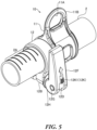
- Fig. 5 to Fig. 7 illustrate the parts of modification examples of the working machine 1 equipped with the hanging tool 10.
- scale lines 2A are applied to the outer circumferential surface of the operating rod 2 as markers to determine the position at which the hanging tool 10 is fixed.
- the scale marks 2A are drawn along the circumference of the operating rod 2 and arranged at a predetermined interval along the longitudinal direction of the operating rod 2 . The shorter the interval each between the scale lines 2A is, the more precisely the position of the hanging tool 10 can be adjusted.
- the end of the stopper 12 or the hanging tool body 11 along the longitudinal direction of the operating rod 2 is aligned with a line of the scale lines 2A. By this means, it is possible to speedily determine the fixing position of the hanging tool 10.
- symbols 2B are applied to the outer circumferential surface of the operating rod 2 as markers to determine the fixing position of the hanging tool 10.
- an opening 11D is provided on the hanging tool body 11 to see the symbols 2B, and a marker such as a notch provided in the opening 11D is aligned with one of the symbols 2B.
- numbers 2C are applied to the outer circumferential surface of the operating rod 2 as markers to determine the fixing position of the hanging tool 10.
- the opening 11D is provided on the hanging tool body 11 to see the numbers 2C, and a marker such as a notch provided in the opening 11D is aligned with one of the numbers 2C. By this means, it is possible to determine the fixing position of the hanging tool 10.
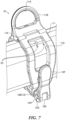
- the operating rod 2 is relatively thick, and the cross section of the operating rod 2 orthogonal to the longitudinal direction is rectangular.
- the hanging tool body 11 includes a hinge mechanism configured to allow the hanging tool body 11 to open and close around a shaft 11E along the longitudinal direction of the operating rod 2. With this hinge mechanism, the hanging tool body 11 can be opened around the shaft 11E and easily be mounted to the thick and rectangular operating rod 2.
- Figs. 8A, 8B and Fig. 9 illustrate modification examples of the lock member 12K.
- the operating lever 12F includes an engaging slot 12F1 to engage with the unlocking part 12K1 of the lock member 12K.
- Fig. 8A illustrates a state where the unlocking part 12K1 is engaged with the engaging slot 12F1 of the operating lever 12F.
- the unlocking part 12K1 is rotated around the longitudinal axis of the lock member 12K at the locking position of the lock member 12K. By this means, the unlocking part 12K1 is engaged with the engaging slot 12F1.
- the unlocking part 12K1 engaged with the engaging slot 12F1 is rotated for 90 degrees in the reverse direction to remove the unlocking part 12K1 from the engaging slot 12F1 as illustrated in Fig. 8B . Then, the unlocking part 12K1 is moved along the longitudinal direction of the lock member 12K to remove the lock member 12K from the lock hole 12M.
- the unlocking part 12K1 is rotated to remove the unlocking part 12K1 from the engaging slot 12F1.
- the unlocking part 12K1 removed from the engaging slot 12F1 is moved along the longitudinal direction of the operating lever 12F to remove the lock member 12K from the lock hole 12M
- the operating lever 12F is operated to allow the head end of the operating lever 12F to move away from the operating rod 2. Therefore, it is more unlikely to release the hanging tool 10 by unintended operation of the worker M.
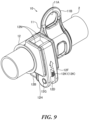
- Fig. 9 illustrates a modification example of the stopper 12.
- accommodation parts 12N are provided to accommodate the operating lever 12F close to the side surface of the operating rod 2.
- the accommodation parts 12N are provided to surround the operating lever 12F so as not to accidentally apply the force of the worker M to the operating lever 12F while the hanging tool 10 is fixed.
- the lock member 12K may be omitted.
- the hanging tool 10 can freely move along the longitudinal direction of the operating rod 2. Therefore, the worker M can move the hanging tool 10 to a desired position . Then, the hanging tool 10 having moved to the desired position for the worker M can be speedily and easily fixed to the operating rod 2 by simple operation of the operating lever 12F.
- the hanging tool 10 is fixed to the operating rod 2 by the operating lever 12F while the operating lever 12F is close to the operating rod 2. Therefore, the operating lever 12F is unlikely to be released by wrong operation of the worker M. Moreover, the operating lever 12 includes the lock member 12K, and therefore it is more unlikely to release the hanging tool 10 without the worker M's intention.
Landscapes
- Life Sciences & Earth Sciences (AREA)
- Environmental Sciences (AREA)
- Engineering & Computer Science (AREA)
- General Engineering & Computer Science (AREA)
- Mechanical Engineering (AREA)
- Harvester Elements (AREA)
- Electric Cable Installation (AREA)
Applications Claiming Priority (1)
| Application Number | Priority Date | Filing Date | Title |
|---|---|---|---|
| JP2023073098A JP2024158143A (ja) | 2023-04-27 | 2023-04-27 | 操作桿付き作業機及び肩掛けベルト用の吊り具 |
Publications (1)
| Publication Number | Publication Date |
|---|---|
| EP4454450A1 true EP4454450A1 (de) | 2024-10-30 |
Family
ID=90904906
Family Applications (1)
| Application Number | Title | Priority Date | Filing Date |
|---|---|---|---|
| EP24172433.5A Pending EP4454450A1 (de) | 2023-04-27 | 2024-04-25 | Arbeitsmaschine mit stange und hänger für schultergurt |
Country Status (3)
| Country | Link |
|---|---|
| US (1) | US12324369B2 (de) |
| EP (1) | EP4454450A1 (de) |
| JP (1) | JP2024158143A (de) |
Citations (5)
| Publication number | Priority date | Publication date | Assignee | Title |
|---|---|---|---|---|
| EP0320576A2 (de) * | 1987-12-17 | 1989-06-21 | White Consolidated Industries, Inc. | Tragbares, rotierendes Gerät |
| JP2000316349A (ja) | 1999-05-14 | 2000-11-21 | Fuji Robin Ind Ltd | 刈払機 |
| WO2015094027A1 (en) * | 2013-12-16 | 2015-06-25 | Husqvarna Ab | Handle arrangement for a power tool |
| CN105519301A (zh) * | 2014-09-28 | 2016-04-27 | 南京德朔实业有限公司 | 打草机 |
| EP4018806A1 (de) * | 2020-12-22 | 2022-06-29 | Globe (Jiangsu) Co., Ltd. | Betätigungsstabanordnung und fadenschneider |
Family Cites Families (2)
| Publication number | Priority date | Publication date | Assignee | Title |
|---|---|---|---|---|
| JP4940090B2 (ja) * | 2007-10-15 | 2012-05-30 | 本田技研工業株式会社 | 刈払機 |
| EP2814641B1 (de) * | 2012-02-15 | 2019-09-04 | Koki Holdings Co., Ltd. | Elektrisches arbeitsgerät |
-
2023
- 2023-04-27 JP JP2023073098A patent/JP2024158143A/ja active Pending
-
2024
- 2024-04-09 US US18/630,096 patent/US12324369B2/en active Active
- 2024-04-25 EP EP24172433.5A patent/EP4454450A1/de active Pending
Patent Citations (5)
| Publication number | Priority date | Publication date | Assignee | Title |
|---|---|---|---|---|
| EP0320576A2 (de) * | 1987-12-17 | 1989-06-21 | White Consolidated Industries, Inc. | Tragbares, rotierendes Gerät |
| JP2000316349A (ja) | 1999-05-14 | 2000-11-21 | Fuji Robin Ind Ltd | 刈払機 |
| WO2015094027A1 (en) * | 2013-12-16 | 2015-06-25 | Husqvarna Ab | Handle arrangement for a power tool |
| CN105519301A (zh) * | 2014-09-28 | 2016-04-27 | 南京德朔实业有限公司 | 打草机 |
| EP4018806A1 (de) * | 2020-12-22 | 2022-06-29 | Globe (Jiangsu) Co., Ltd. | Betätigungsstabanordnung und fadenschneider |
Also Published As
| Publication number | Publication date |
|---|---|
| US12324369B2 (en) | 2025-06-10 |
| JP2024158143A (ja) | 2024-11-08 |
| US20240357961A1 (en) | 2024-10-31 |
Similar Documents
| Publication | Publication Date | Title |
|---|---|---|
| US20150040408A1 (en) | Dual axis hook assembly for a power tool | |
| US9676115B2 (en) | Guide bar fastening device for chain saw | |
| CN110115165B (zh) | 园艺和/或林艺设备 | |
| CA2493219C (en) | Quick-connect chuck mechanism | |
| EP2433754A1 (de) | Elektrowerkzeug | |
| EP4454450A1 (de) | Arbeitsmaschine mit stange und hänger für schultergurt | |
| EP2678137B1 (de) | Werkzeugstützvorrichtung | |
| US11394183B2 (en) | Knife accessory for hot stick | |
| US20100207082A1 (en) | Tool with Prying and Clamping Devices | |
| US11007815B1 (en) | Shaking adapter for a power tool | |
| WO2018089746A1 (en) | Blade clamp for a reciprocating power tool | |
| DE202013012558U1 (de) | System und Werkzeug | |
| US6865760B2 (en) | Tool holder and cord locking means | |
| DE10260324B4 (de) | Elektrisches Werkzeug | |
| DE102010038509A1 (de) | Handwerkzeugmaschine | |
| US20220311224A1 (en) | Knife Accessory for Hot Stick | |
| US11185910B2 (en) | Cotter pin forming tool | |
| US6802125B2 (en) | Cable-stripping tool | |
| US7681315B2 (en) | Clamping pliers | |
| KR100446254B1 (ko) | 트랙터용 연결장치 | |
| US5881612A (en) | Finger guard for tubenut tools | |
| DE102011089758A1 (de) | Schutzhaubenverdrehsicherungsvorrichtung | |
| US8915680B2 (en) | Tool protection devices | |
| EP4529503B1 (de) | Werkzeugmaschinenvorrichtung, werkzeugmaschine und system | |
| US20250215710A1 (en) | Tool, cover for tool, and locking body for tool |
Legal Events
| Date | Code | Title | Description |
|---|---|---|---|
| PUAI | Public reference made under article 153(3) epc to a published international application that has entered the european phase |
Free format text: ORIGINAL CODE: 0009012 |
|
| STAA | Information on the status of an ep patent application or granted ep patent |
Free format text: STATUS: THE APPLICATION HAS BEEN PUBLISHED |
|
| AK | Designated contracting states |
Kind code of ref document: A1 Designated state(s): AL AT BE BG CH CY CZ DE DK EE ES FI FR GB GR HR HU IE IS IT LI LT LU LV MC ME MK MT NL NO PL PT RO RS SE SI SK SM TR |
|
| STAA | Information on the status of an ep patent application or granted ep patent |
Free format text: STATUS: REQUEST FOR EXAMINATION WAS MADE |
|
| 17P | Request for examination filed |
Effective date: 20250425 |