EP4451068A1 - Kupplung für chronograph - Google Patents
Kupplung für chronograph Download PDFInfo
- Publication number
- EP4451068A1 EP4451068A1 EP23169219.5A EP23169219A EP4451068A1 EP 4451068 A1 EP4451068 A1 EP 4451068A1 EP 23169219 A EP23169219 A EP 23169219A EP 4451068 A1 EP4451068 A1 EP 4451068A1
- Authority
- EP
- European Patent Office
- Prior art keywords
- wheel
- clutch
- mobile
- input
- output
- Prior art date
- Legal status (The legal status is an assumption and is not a legal conclusion. Google has not performed a legal analysis and makes no representation as to the accuracy of the status listed.)
- Withdrawn
Links
Images

Classifications
-
- G—PHYSICS
- G04—HOROLOGY
- G04F—TIME-INTERVAL MEASURING
- G04F7/00—Apparatus for measuring unknown time intervals by non-electric means
- G04F7/04—Apparatus for measuring unknown time intervals by non-electric means using a mechanical oscillator
- G04F7/08—Watches or clocks with stop devices, e.g. chronograph
- G04F7/0823—Watches or clocks with stop devices, e.g. chronograph with couplings between the chronograph mechanism and the base movement
- G04F7/0833—Watches or clocks with stop devices, e.g. chronograph with couplings between the chronograph mechanism and the base movement acting perpendicular to the plane of the movement
Definitions
- the present invention relates to the field of watchmaking. It concerns, more particularly, a vertical clutch for a chronograph.
- So-called "vertical” clutches are commonly used to make a disengageable kinematic link between the finishing gear of a watch movement and a chronograph mechanism. They have the advantage of being compact in the plane of the movement and, when the clutch is actuated, there is no risk of the seconds counter jumping when the clutch is actuated since the drive is carried out by means of friction instead of cooperation between teeth as is the case in a horizontal clutch or a sliding pinion clutch.
- a classic vertical clutch comprises an input wheel in permanent kinematic connection with the finishing gear or even being integrated into the latter, as well as an output wheel, which is coaxial with the input wheel and is mounted on a common axis, one or the other of the input wheel and the output wheel being able to pivot relatively with respect to the common axis.
- a friction disk integral in rotation with the output wheel, is arranged on said axis between said wheels, and is held in contact with the input wheel by an elastic element in order to make said wheels integral in rotation by means of the friction acting between the input wheel and the clutch disk.
- a clamp or a lever can lift the clutch disk against the force of the elastic element, and thus break the contact between the clutch disk and the input wheel. In doing so, the kinematic connection between the input wheel and the output wheel is thus broken.
- the clamp or lever is typically operated by a column wheel, shuttle, cam or the like, for the purpose of stopping or starting the time counting.
- the clutch is disengaged, and one or more hammers act on cams to return the counters to a zero indication.
- the clutch output wheel When rotating the counters, the clutch output wheel may be driven, and construction clearances may cause the clutch to re-engage, and a play must be taken up before the chronograph is driven again. This delays the start of the counters.
- the aim of the invention is therefore to provide a chronograph clutch in which the aforementioned defects are at least partially overcome.
- said clutch further comprises a braking wheel coaxial with said input wheel and in gentle frictional contact with the latter, said braking wheel being arranged to cooperate with a brake, arranged to be controlled in synchronism with a reset hammer, such that the brake blocks said braking wheel when resetting said chronograph.
- said brake wheel has a toothing having a module of at most 50%, preferably at most 25%, of that of said input wheel. Undesired pivoting of the brake wheel during its cooperation with said brake can thus be minimized, or even eliminated.
- the input wheel had a toothing module of 0.07mm, and that of the brake wheel was 0.016mm, the ratio therefore being 23%.
- said brake comprises a beak arranged to cooperate with said teeth of said braking wheel.
- brakes operating by friction or the like are also possible.
- said brake is pivotally mounted between a first position, in which it is distant from said braking wheel which is therefore not not blocked, and a second position, in which it cooperates with said braking wheel to block it.
- said brake is controlled to move between said first and second positions by a cam controlled by said hammer, or alternatively any other type of element fulfilling this function (such as a rocker, a lever etc.), preferably by means of a rack carried by the latter.
- a cam controlled by said hammer or alternatively any other type of element fulfilling this function (such as a rocker, a lever etc.), preferably by means of a rack carried by the latter.
- a shaped cam, a rake or any other suitable element can serve the same purpose, but the solution implementing a cam and a rack is particularly simple and compact.
- said output mobile is integral in rotation with said clutch disc, while said input mobile is mounted idly on said axis.
- said input wheel is mounted loosely on an intermediate ring which is also mounted loosely on said axle, said braking wheel being integral in rotation with said intermediate ring.
- said contact between said input mobile and said braking wheel is ensured by means of a plurality of contact elements carried by one or the other of said input mobile and said braking wheel, preferably by said braking wheel. This facilitates the control of friction between the braking wheel and the input mobile.
- said contact elements are made of ruby, but alternatively they can be made of diamond, synthetic diamond or any other material having a low coefficient of friction.
- said clutch disc is made integral in rotation with said output wheel by means of said elastic element, but, of course, other alternative solutions are known to those skilled in the art.
- Said brake is arranged so as to block said locking wheel when resetting said chronograph.
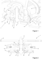
- the clutch 1 is of the vertical type, its main components being arranged on an axis 3.
- This clutch 1 is suitable for use in connection with a chronograph mechanism, which is to be understood in the broad sense, encompassing any type of counting of a unit of time that can be engaged and triggered at will, whether it is a classic chronograph, a countdown or similar.
- an input wheel set 5 is mounted loosely on the axis 3, and meshes directly or indirectly with a wheel set 7 of the finishing gear train, typically the seconds wheel set, but this can be chosen at will.
- a wheel set 7 of the finishing gear train typically the seconds wheel set, but this can be chosen at will.
- an output wheel set 9 which is rotationally integral with said axis 3 and which meshes directly or indirectly with at least one chronograph counter (not shown). The ratio of the diameters between the wheels 5, 9 can be chosen at will, but in the illustrated embodiment, the output wheel set 9 has a larger diameter than that of the input wheel set 5.
- a clutch disc 11 is provided between the input mobile 5 and the output mobile 9.
- This clutch disc 11 is movable in translation along the axis 3 and is subjected to a restoring force by means of an elastic element 13, in order to maintain it in a first position against a lateral face of the input mobile 5 such that the cooperation between these two elements generates sufficient friction to make them integral in rotation, and this for any torque to which the clutch 1 will be subjected during operation.
- the clutch disc 11 can slide on the axis 3, at least in a longitudinal direction, and is made integral in rotation with the output wheel set 9 by means of the particular shape of the elastic element 13, which comprises a central part 13a having an opening of non-circular shape mounted on a section 3a of non-circular section complementary to said axis 3, as well as by the ends 13b of a plurality of arms 13c which engage with respective notches 11a provided in the clutch disc.
- the elastic element 13 which comprises a central part 13a having an opening of non-circular shape mounted on a section 3a of non-circular section complementary to said axis 3, as well as by the ends 13b of a plurality of arms 13c which engage with respective notches 11a provided in the clutch disc.
- the arms 13c of the elastic element 13 are pre-stressed (it should be noted that, in the figures, the arms 13c are illustrated without pre-stress, but the person skilled in the art understands that, when the ends 13b are engaged in the notches 11a, the arms 13c will be bent) so as to provide sufficient force to press the clutch disc 11 against the face of the input wheel set 5 as mentioned above.
- the clutch disc 11 is further adapted and dimensioned to cooperate with an actuator 12 such as a clamp or a lever (illustrated schematically as a clamp on the figure 2 ) in a known manner, to lift the clutch disc 11 against the restoring force provided by the elastic element 13 to put it in a second position and thus break the kinematic connection between the input mobile 5 and the output mobile 9. in this way, in the disengaged state of the clutch 1, the input mobile 5 can pivot relatively with respect to the output mobile 9.
- an actuator 12 such as a clamp or a lever (illustrated schematically as a clamp on the figure 2 ) in a known manner
- the input mobile 5 is mounted on the axis 3 by an intermediate ring 15 which is integral in rotation with a bearing 17, typically a ruby ring, but this component can be omitted in the case where its function can be taken over by the intermediate ring 15, for example in the case where the latter is provided with a layer of hard material such as adamantine carbon or similar.
- the bearing 17 is mounted loosely on the shaft 3, and the input wheel set 5 is mounted loosely on the intermediate ring 15.
- the latter comprises a shoulder 3b against which the bearing 17 is placed, and a retaining ring 19 is fixed on the shaft 3 opposite the shoulder 3b such that the bearing 17 is axially partitioned (with the exception of an operating clearance) between these two elements 3b, 19.
- a braking wheel 21 is mounted so as to rotate securely with the intermediate ring 15, and cooperates by friction with the input wheel set 5, by means of a plurality of contact elements 25.
- the latter are illustrated here in the form of pierced stones made of ruby or other hard material, but may alternatively be formed by studs, bumps or the like, or even by simple side-to-side contact with the input wheel set 5.
- a brake 27 cooperates with the periphery of the braking wheel 21.
- the brake 27 is a beak pivotally mounted on a frame element (not illustrated) which cooperates with peripheral teeth whose module is less than that of the input wheel 5.
- the module of the teeth of the braking wheel 21 is between 1/6 and 1/2, preferably between 1/5 and 1/3, of that of the input wheel 5.
- the brake can cooperate with the periphery of the braking wheel 21 by friction.
- the brake 27 is controlled as a function of the movements of the chronograph reset hammer.
- the hammer comprises a rack 29 which cooperates with a pinion 30 integral in rotation with a cam 33.
- the latter cooperates with a feeler 27a which is integral with the brake 27 and which causes the latter to pivot to generate its cooperation with the braking wheel 21 when the hammer cooperates with the counter reset cams (not illustrated).
- the hammer may comprise a shaped cam (without teeth), a rack or any other suitable element instead of the rack 29, and the cam 33 may be replaced by a rocker, a lever, a finger or any other suitable element.
- still other arrangements controlled directly or indirectly by a column wheel, a shuttle, a control cam or the like are also possible.
- the input wheel 5 is prevented from rotating in the wrong direction when resetting, and the aforementioned play recovery is thus avoided.
- the entire range of materials used in contemporary watchmaking can be considered (metals, non-metals such as silicon, silicon compounds, synthetic diamond, sapphire, structurable glasses, ceramics, glass-ceramics, metallic glasses, polymers, composites, materials that can be manufactured additively, etc.).
- metals non-metals such as silicon, silicon compounds, synthetic diamond, sapphire, structurable glasses, ceramics, glass-ceramics, metallic glasses, polymers, composites, materials that can be manufactured additively, etc.
- flexible pivots can be used for elements where this makes technical sense.
Landscapes
- Physics & Mathematics (AREA)
- General Physics & Mathematics (AREA)
- Measurement Of Unknown Time Intervals (AREA)
Priority Applications (3)
| Application Number | Priority Date | Filing Date | Title |
|---|---|---|---|
| EP23169219.5A EP4451068A1 (de) | 2023-04-21 | 2023-04-21 | Kupplung für chronograph |
| PCT/EP2024/060477 WO2024218183A1 (fr) | 2023-04-21 | 2024-04-18 | Embrayage pour chronographe |
| EP24718844.4A EP4698955A1 (de) | 2023-04-21 | 2024-04-18 | Kupplung für chronograph |
Applications Claiming Priority (1)
| Application Number | Priority Date | Filing Date | Title |
|---|---|---|---|
| EP23169219.5A EP4451068A1 (de) | 2023-04-21 | 2023-04-21 | Kupplung für chronograph |
Publications (1)
| Publication Number | Publication Date |
|---|---|
| EP4451068A1 true EP4451068A1 (de) | 2024-10-23 |
Family
ID=86142644
Family Applications (2)
| Application Number | Title | Priority Date | Filing Date |
|---|---|---|---|
| EP23169219.5A Withdrawn EP4451068A1 (de) | 2023-04-21 | 2023-04-21 | Kupplung für chronograph |
| EP24718844.4A Pending EP4698955A1 (de) | 2023-04-21 | 2024-04-18 | Kupplung für chronograph |
Family Applications After (1)
| Application Number | Title | Priority Date | Filing Date |
|---|---|---|---|
| EP24718844.4A Pending EP4698955A1 (de) | 2023-04-21 | 2024-04-18 | Kupplung für chronograph |
Country Status (2)
| Country | Link |
|---|---|
| EP (2) | EP4451068A1 (de) |
| WO (1) | WO2024218183A1 (de) |
Citations (2)
| Publication number | Priority date | Publication date | Assignee | Title |
|---|---|---|---|---|
| EP2015145A1 (de) * | 2007-06-11 | 2009-01-14 | Chopard Manufacture SA | Vertikale Kupplungsvorrichtung für Uhr |
| EP3869278A1 (de) | 2020-02-21 | 2021-08-25 | Montres Breguet S.A. | Vertikale kupplungsvorrichtung für uhr |
-
2023
- 2023-04-21 EP EP23169219.5A patent/EP4451068A1/de not_active Withdrawn
-
2024
- 2024-04-18 EP EP24718844.4A patent/EP4698955A1/de active Pending
- 2024-04-18 WO PCT/EP2024/060477 patent/WO2024218183A1/fr not_active Ceased
Patent Citations (2)
| Publication number | Priority date | Publication date | Assignee | Title |
|---|---|---|---|---|
| EP2015145A1 (de) * | 2007-06-11 | 2009-01-14 | Chopard Manufacture SA | Vertikale Kupplungsvorrichtung für Uhr |
| EP3869278A1 (de) | 2020-02-21 | 2021-08-25 | Montres Breguet S.A. | Vertikale kupplungsvorrichtung für uhr |
Also Published As
| Publication number | Publication date |
|---|---|
| WO2024218183A1 (fr) | 2024-10-24 |
| EP4698955A1 (de) | 2026-02-25 |
Similar Documents
| Publication | Publication Date | Title |
|---|---|---|
| EP2541346B1 (de) | Vorrichtung zum Zurückstellen eines Anzeigeorgans für eine mit der Zeit zusammenhängenden Größe in eine voreingestellte Position | |
| CH709508A2 (fr) | Mouvement horloger muni d'un mécanisme d'entraînement d'un indicateur analogique à déplacement périodique ou intermittent. | |
| EP3144743B1 (de) | Uhrwerk mit einem datumskorrektur-mechanismus | |
| EP3143463B1 (de) | Schnellkorrekturmechanismus für uhr | |
| EP3602202B1 (de) | Vorrichtung zur einstellung von funktionen einer uhr | |
| EP2269119B1 (de) | Stossdämpfereinrichtung für das steuerglied einer uhr | |
| EP3483663A1 (de) | Antriebsvorrichtung für kalendersystem einer uhr | |
| WO2015193400A1 (fr) | Dispositif horloger de transmission | |
| EP2798413A2 (de) | Feder für ein uhrwerk | |
| FR2793856A1 (fr) | Groupe structurel a plaque de pression pour embrayage a friction de vehicule automobile avec compensation automatique de l'usure | |
| FR2564921A1 (fr) | Dispositif pour maintenir en permanence une butee de debrayage en appui sur un mecanisme d'embrayage | |
| EP2226687B1 (de) | Auskupplungsvorrichtung für Uhrwerksmechanismus und diese Vorrichtung umfassendes Uhrwerk | |
| EP4451068A1 (de) | Kupplung für chronograph | |
| CH720723A2 (fr) | Embrayage pour chronographe | |
| EP2798414B1 (de) | Feder für uhrwerk | |
| EP3026506B1 (de) | Zeitmessgerät mit Geschwindigkeitswahlschalter | |
| EP2919077B1 (de) | Antriebsvorrichtung einer analoganzeige, insbesondere eines datumsanzeigerings | |
| EP3542226B1 (de) | Kupplungssystem für chronograph | |
| EP1960843B1 (de) | Uhrwerk | |
| EP3786724A1 (de) | Stossdämpfungs- und/oder anti-doppelsprung-mechanismus für uhrwerk einer uhr | |
| CH716774B9 (fr) | Dispositif horloger de couplage et d'indexation. | |
| EP1960846B1 (de) | Uhrwerk | |
| EP0129683A1 (de) | Datumschaltwerk für Uhren | |
| EP3969964B1 (de) | Uhrwerk einer armbanduhr mit automatischem aufzug | |
| EP3742236B1 (de) | Uhrvorrichtung, die eine erste komponente umfasst, die auf einer zweiten komponente durch plastische verformung fixiert ist |
Legal Events
| Date | Code | Title | Description |
|---|---|---|---|
| PUAI | Public reference made under article 153(3) epc to a published international application that has entered the european phase |
Free format text: ORIGINAL CODE: 0009012 |
|
| STAA | Information on the status of an ep patent application or granted ep patent |
Free format text: STATUS: THE APPLICATION HAS BEEN PUBLISHED |
|
| AK | Designated contracting states |
Kind code of ref document: A1 Designated state(s): AL AT BE BG CH CY CZ DE DK EE ES FI FR GB GR HR HU IE IS IT LI LT LU LV MC ME MK MT NL NO PL PT RO RS SE SI SK SM TR |
|
| STAA | Information on the status of an ep patent application or granted ep patent |
Free format text: STATUS: THE APPLICATION IS DEEMED TO BE WITHDRAWN |
|
| 18D | Application deemed to be withdrawn |
Effective date: 20250424 |