EP4450181A2 - Geflanschter und konischer stift für ein verfahren zur automatisierung der teilladung und -entladung - Google Patents
Geflanschter und konischer stift für ein verfahren zur automatisierung der teilladung und -entladung Download PDFInfo
- Publication number
- EP4450181A2 EP4450181A2 EP24159598.2A EP24159598A EP4450181A2 EP 4450181 A2 EP4450181 A2 EP 4450181A2 EP 24159598 A EP24159598 A EP 24159598A EP 4450181 A2 EP4450181 A2 EP 4450181A2
- Authority
- EP
- European Patent Office
- Prior art keywords
- forming die
- hot box
- securing pin
- pin
- forming
- Prior art date
- Legal status (The legal status is an assumption and is not a legal conclusion. Google has not performed a legal analysis and makes no representation as to the accuracy of the status listed.)
- Pending
Links
Images


Classifications
-
- B—PERFORMING OPERATIONS; TRANSPORTING
- B30—PRESSES
- B30B—PRESSES IN GENERAL
- B30B1/00—Presses, using a press ram, characterised by the features of the drive therefor, pressure being transmitted directly, or through simple thrust or tension members only, to the press ram or platen
- B30B1/32—Presses, using a press ram, characterised by the features of the drive therefor, pressure being transmitted directly, or through simple thrust or tension members only, to the press ram or platen by plungers under fluid pressure
-
- B—PERFORMING OPERATIONS; TRANSPORTING
- B21—MECHANICAL METAL-WORKING WITHOUT ESSENTIALLY REMOVING MATERIAL; PUNCHING METAL
- B21D—WORKING OR PROCESSING OF SHEET METAL OR METAL TUBES, RODS OR PROFILES WITHOUT ESSENTIALLY REMOVING MATERIAL; PUNCHING METAL
- B21D22/00—Shaping without cutting, by stamping, spinning, or deep-drawing
- B21D22/02—Stamping using rigid devices or tools
- B21D22/022—Stamping using rigid devices or tools by heating the blank or stamping associated with heat treatment
-
- B—PERFORMING OPERATIONS; TRANSPORTING
- B21—MECHANICAL METAL-WORKING WITHOUT ESSENTIALLY REMOVING MATERIAL; PUNCHING METAL
- B21D—WORKING OR PROCESSING OF SHEET METAL OR METAL TUBES, RODS OR PROFILES WITHOUT ESSENTIALLY REMOVING MATERIAL; PUNCHING METAL
- B21D22/00—Shaping without cutting, by stamping, spinning, or deep-drawing
- B21D22/20—Deep-drawing
- B21D22/208—Deep-drawing by heating the blank or deep-drawing associated with heat treatment
-
- B—PERFORMING OPERATIONS; TRANSPORTING
- B21—MECHANICAL METAL-WORKING WITHOUT ESSENTIALLY REMOVING MATERIAL; PUNCHING METAL
- B21D—WORKING OR PROCESSING OF SHEET METAL OR METAL TUBES, RODS OR PROFILES WITHOUT ESSENTIALLY REMOVING MATERIAL; PUNCHING METAL
- B21D37/00—Tools as parts of machines covered by this subclass
- B21D37/10—Die sets; Pillar guides
-
- B—PERFORMING OPERATIONS; TRANSPORTING
- B21—MECHANICAL METAL-WORKING WITHOUT ESSENTIALLY REMOVING MATERIAL; PUNCHING METAL
- B21D—WORKING OR PROCESSING OF SHEET METAL OR METAL TUBES, RODS OR PROFILES WITHOUT ESSENTIALLY REMOVING MATERIAL; PUNCHING METAL
- B21D37/00—Tools as parts of machines covered by this subclass
- B21D37/10—Die sets; Pillar guides
- B21D37/12—Particular guiding equipment, e.g. pliers; Special arrangements for interconnection or cooperation of dies
-
- B—PERFORMING OPERATIONS; TRANSPORTING
- B21—MECHANICAL METAL-WORKING WITHOUT ESSENTIALLY REMOVING MATERIAL; PUNCHING METAL
- B21D—WORKING OR PROCESSING OF SHEET METAL OR METAL TUBES, RODS OR PROFILES WITHOUT ESSENTIALLY REMOVING MATERIAL; PUNCHING METAL
- B21D37/00—Tools as parts of machines covered by this subclass
- B21D37/16—Heating or cooling
-
- B—PERFORMING OPERATIONS; TRANSPORTING
- B21—MECHANICAL METAL-WORKING WITHOUT ESSENTIALLY REMOVING MATERIAL; PUNCHING METAL
- B21D—WORKING OR PROCESSING OF SHEET METAL OR METAL TUBES, RODS OR PROFILES WITHOUT ESSENTIALLY REMOVING MATERIAL; PUNCHING METAL
- B21D43/00—Feeding, positioning or storing devices combined with, or arranged in, or specially adapted for use in connection with, apparatus for working or processing sheet metal, metal tubes or metal profiles; Associations therewith of cutting devices
- B21D43/003—Positioning devices
-
- B—PERFORMING OPERATIONS; TRANSPORTING
- B21—MECHANICAL METAL-WORKING WITHOUT ESSENTIALLY REMOVING MATERIAL; PUNCHING METAL
- B21D—WORKING OR PROCESSING OF SHEET METAL OR METAL TUBES, RODS OR PROFILES WITHOUT ESSENTIALLY REMOVING MATERIAL; PUNCHING METAL
- B21D43/00—Feeding, positioning or storing devices combined with, or arranged in, or specially adapted for use in connection with, apparatus for working or processing sheet metal, metal tubes or metal profiles; Associations therewith of cutting devices
- B21D43/02—Advancing work in relation to the stroke of the die or tool
- B21D43/04—Advancing work in relation to the stroke of the die or tool by means in mechanical engagement with the work
- B21D43/06—Advancing work in relation to the stroke of the die or tool by means in mechanical engagement with the work by positive or negative engaging parts co-operating with corresponding parts of the sheet or the like to be processed, e.g. carrier bolts or grooved section in the carriers
-
- B—PERFORMING OPERATIONS; TRANSPORTING
- B21—MECHANICAL METAL-WORKING WITHOUT ESSENTIALLY REMOVING MATERIAL; PUNCHING METAL
- B21D—WORKING OR PROCESSING OF SHEET METAL OR METAL TUBES, RODS OR PROFILES WITHOUT ESSENTIALLY REMOVING MATERIAL; PUNCHING METAL
- B21D43/00—Feeding, positioning or storing devices combined with, or arranged in, or specially adapted for use in connection with, apparatus for working or processing sheet metal, metal tubes or metal profiles; Associations therewith of cutting devices
- B21D43/02—Advancing work in relation to the stroke of the die or tool
- B21D43/04—Advancing work in relation to the stroke of the die or tool by means in mechanical engagement with the work
- B21D43/10—Advancing work in relation to the stroke of the die or tool by means in mechanical engagement with the work by grippers
- B21D43/105—Manipulators, i.e. mechanical arms carrying a gripper element having several degrees of freedom
-
- B—PERFORMING OPERATIONS; TRANSPORTING
- B21—MECHANICAL METAL-WORKING WITHOUT ESSENTIALLY REMOVING MATERIAL; PUNCHING METAL
- B21D—WORKING OR PROCESSING OF SHEET METAL OR METAL TUBES, RODS OR PROFILES WITHOUT ESSENTIALLY REMOVING MATERIAL; PUNCHING METAL
- B21D43/00—Feeding, positioning or storing devices combined with, or arranged in, or specially adapted for use in connection with, apparatus for working or processing sheet metal, metal tubes or metal profiles; Associations therewith of cutting devices
- B21D43/02—Advancing work in relation to the stroke of the die or tool
- B21D43/04—Advancing work in relation to the stroke of the die or tool by means in mechanical engagement with the work
- B21D43/10—Advancing work in relation to the stroke of the die or tool by means in mechanical engagement with the work by grippers
- B21D43/11—Advancing work in relation to the stroke of the die or tool by means in mechanical engagement with the work by grippers for feeding sheet or strip material
-
- B—PERFORMING OPERATIONS; TRANSPORTING
- B30—PRESSES
- B30B—PRESSES IN GENERAL
- B30B15/00—Details of, or accessories for, presses; Auxiliary measures in connection with pressing
- B30B15/02—Dies; Inserts therefor; Mounting thereof; Moulds
-
- B—PERFORMING OPERATIONS; TRANSPORTING
- B30—PRESSES
- B30B—PRESSES IN GENERAL
- B30B15/00—Details of, or accessories for, presses; Auxiliary measures in connection with pressing
- B30B15/06—Platens or press rams
- B30B15/062—Press plates
- B30B15/064—Press plates with heating or cooling means
-
- B—PERFORMING OPERATIONS; TRANSPORTING
- B30—PRESSES
- B30B—PRESSES IN GENERAL
- B30B15/00—Details of, or accessories for, presses; Auxiliary measures in connection with pressing
- B30B15/34—Heating or cooling presses or parts thereof
Definitions
- This application is directed to flanged and tapered pins for method to automate part loading and unloading.
- Hot-forming presses are expensive.
- a hot-forming press capable of processing large parts, may cost in excess of US$2.5 million and even as much as US$10 million.
- conventional hot-forming presses require expensive maintenance and are subject to unpredictable down-time, which adversely effects manufacturing cycle time.
- expensive rework of parts, being processed by the press at the time of failure is often needed. As a worst-case scenario, such parts must be scrapped, resulting in significant additional costs.
- Part loading of hot forming tools normally is done manually and requires an operator to wear heat protective equipment/clothing. During the load/unload step, operators are required to be in close contact with the part, the tool, and the press components which can be in excess of 1700°F (925°C). Manually loaded and unloaded parts can result in variations to part contour due to operators employing different load and unload methods. Automated loading and unloading could provide a safer environment for operators requiring less close interaction with hot components.
- the forming die comprises a lower forming die portion comprising a lower pin receiving opening for receiving a lower portion of a removable securing pin that secures a lower surface of a part to be formed to the lower forming die; and an upper forming die portion, positionable above the lower forming die portion, comprising an upper pin receiving opening for receiving an upper portion of the removable securing pin that secures an upper surface of the part to be formed to the upper forming die portion.
- the lower forming die portion is housed in a lower hot box portion, wherein the lower hot box portion comprises a lower housing, a lower heating platen, received within the lower housing and configured to support the lower forming die portion, and a lower hot box portion pin receiving opening for receiving the lower portion of the removable securing pin that secures the lower surface of the part to be formed to the lower housing and the lower heating platen.
- the upper forming die portion is housed in an upper hot box portion, positionable above the lower hot box portion, wherein the upper hot box portion comprises an upper housing, an upper heating platen, received within the upper housing and configured to support the upper forming die portion, and an upper hot box portion pin receiving opening for receiving the upper portion of the removable securing pin that secures an upper surface of the part to be formed to the upper housing and the upper heating platen.
- the forming die further comprises the removable securing pin.
- the lower portion of the removable securing pin comprises a tapered surface that is clearance fit into the lower pin receiving opening that is reciprocally tapered to provide for removal and positioning of the part.
- the upper portion of the removable securing pin comprises a flange that provides a ledge on which the part rests, enables lifting of the part, and that connects a top surface of the lower pin receiving opening.
- the upper portion of the removable securing pin comprises a recessed ridge that allows for gripping the removeable securing pin.
- the end effector further comprises a thermal pad that provides a thermal break between the lower forming die portion and a gripper from an end effector.
- the lower hot box portion and the upper hot box portion are removable from a press assembly.
- the hot box comprises a lower hot box portion, comprising: a lower housing, a lower heating platen, received within the lower housing and configured to support a lower forming die portion, and a lower pin receiving opening for receiving a lower portion of a removable securing pin that secures a lower surface of a part to be formed to the lower housing and the lower heating platen and an upper hot box portion, positionable above the lower hot box portion and comprising: an upper housing, an upper heating platen, received within the upper housing and configured to support an upper forming die portion, and a upper pin receiving opening for receiving an upper portion of the removable securing pin that secures an upper surface of the part to be formed to the upper housing and the upper heating platen.
- the hot box further comprises the removable securing pin.
- the lower portion of the removable securing pin comprises a tapered surface that is clearance fit into the lower pin receiving opening that is reciprocally tapered to provide for removal and positioning of the part.
- the upper portion of the removable securing pin comprises a flange that provides a ledge on which the part rests, enables lifting of the part, and that connects a top surface of the lower pin receiving opening.
- the upper portion of the removable securing pin comprises a recessed ridge that allows for gripping the removeable securing pin.
- the end effector further comprises a thermal pad that provides a thermal break between the lower forming die portion and a gripper from an end effector.
- a system comprising an end effector; and a gripper attached to the end effector that grips a securing pin that secures a part to a lower hot box portion of a hot box, wherein the securing pin comprises a tapered lower body portion, a flange arranged between the lower body portion and an upper body portion, and a recessed ridge arranged above the flange that allows the gripper to hold the securing pin.
- the system comprises a part handling robot, a user-controlled platform, a computer-controlled platform, or a part-handling frame.
- a part securing pin comprising a tapered lower body portion; an upper body portion; a flange arranged between the lower body portion and the upper body portion; and a recessed ridge arranged above the flange that allows a gripper to hold the hot box securing pin.
- the method comprises securing the part to be formed to a platform using a securing pin, wherein the platform comprises an end effector and a gripper attached to the end effector a securing pin; moving the part to be formed using the securing pin to a lower hot box portion of the hot box in a hot box press assembly; and releasing the part by actuating the gripper to release the securing pin.
- SPF superplastic forming
- the press comprises a lower press assembly and an upper press assembly.
- the lower press assembly is movable along a vertical axis and comprises a lower forming die portion, and a lower hot box portion, configured to receive the lower forming die portion.
- the upper press assembly is movable along the vertical axis above the lower press assembly and comprises an upper forming die portion, and an upper hot box portion.
- the upper hot box portion is configured to receive the upper forming die portion so that the upper forming die portion is positioned opposite the lower forming die portion.
- the lower forming die portion and the upper forming die portion are configured to apply a forming pressure to a workpiece that is received between the lower forming die portion and the upper forming die portion.
- the lower hot box portion and the upper hot box portion are configured to heat the workpiece.
- the component(s) of the press that apply a forming force to generate the forming pressure (i.e., the tonnage of the press) for application to the workpiece need not have a significant stroke length that accounts both for operative placement of the workpiece and removal of a formed part from the press and for application of the forming force.
- the component(s) of the press that apply a forming force to generate the forming pressure need not have a stroke length that also accounts for removal and replacement of the lower forming die portion and the upper forming die portion. Accordingly, the component(s) of the press that apply the forming force to generate the forming pressure undergo less stress over the same number of cycles than prior art presses, thus requiring less maintenance and repair over the lifetime of the press.
- the hot box comprises a lower hot box portion and an upper hot box portion.
- the lower hot box portion comprises a lower housing, a lower heating platen, and a lower insulation layer.
- the lower heating platen is received within the lower housing and is configured to support a lower forming die portion.
- the lower insulation layer is positioned between the lower housing and the lower heating platen.
- the upper hot box portion is positionable above the lower hot box portion and comprises an upper housing, an upper heating platen, and an upper insulation layer.
- the upper heating platen is received within the upper housing and is configured to support an upper forming die portion.
- the upper insulation layer is positioned between the upper housing and the upper heating platen.
- the lower hot box portion and the upper hot box portion provide a thermal barrier around a workpiece that is received between the lower forming die portion and the upper forming die portion, when the lower hot box portion and the upper hot box portion are in contact with each other.
- the hot box provides a thermal barrier to maintain the heat delivered to the lower forming die portion and the upper forming die portion, and thus to the workpiece, when the press is operatively forming a part from the workpiece.
- the lower housing provides structure for supporting the other components of the lower hot box portion.
- the lower insulation layer insulates the lower heating platen, which is configured to support the lower forming die portion and conduct heat thereto, and thereby facilitates efficient heating of the lower forming die portion by restricting conduction away from the lower forming die portion.
- the upper housing provides structure for supporting the other components of the upper hot box portion.
- the upper insulation layer insulates the upper heating platen, which is configured to support the upper forming die portion and conduct heat thereto, and thereby facilitates efficient heating of the upper forming die portion by restricting conduction away from the upper forming die portion.
- the method comprises a step of vertically moving both a lower press assembly and an upper press assembly to a loading configuration, in which the lower press assembly and the upper press assembly are spaced-apart to receive the workpiece.
- the method comprises a step of positioning the workpiece between a lower forming die portion of the lower press assembly and an upper forming die portion of the upper press assembly.
- the method further comprises a step of vertically moving both the lower press assembly and the upper press assembly to a closed configuration, in which the lower press assembly and the upper press assembly are positioned to apply a forming pressure to the workpiece.
- the method also comprises a step of immobilizing the upper press assembly.
- the method further comprises a step of moving the lower press assembly toward the upper press assembly to apply the forming pressure to the workpiece.
- the method also comprises a step of heating the workpiece.
- the component(s) of the press that apply a forming force to generate the forming pressure (i.e., the tonnage of the press) for application to the workpiece need not have a significant stroke length that accounts both for operative placement of the workpiece and removal of a formed part from the press and for application of the forming force.
- the component(s) of the press that apply a forming force to generate the forming pressure need not have a stroke length that also accounts for removal and replacement of the lower forming die portion and the upper forming die portion. Accordingly, the component(s) of the press that apply the forming force to generate the forming pressure undergo less stress over the same number of cycles than prior art presses, thus requiring less maintenance and repair over the lifetime of the press.
- the component(s) associated with vertically moving the upper press assembly need not be capable of applying a forming force that is sufficient to generate the required forming pressure to operatively deform the workpiece. Rather, only the component(s) associated with vertically moving the lower press assembly need be capable of applying a forming force that is sufficient to generate the required forming pressure to operatively deform the workpiece. As a result, the component(s) associated with vertically moving the upper press assembly may be significantly less expensive than the component(s) associated with vertically moving the lower press assembly.
- the method comprises a step of delivering an actively determined amount of heat to distinct lower regions of a lower heating platen of a lower hot box portion of a hot box of a press or to distinct upper regions of an upper heating platen of an upper hot box portion of the hot box.
- the component(s) of the press that apply a forming force to generate the forming pressure (i.e., the tonnage of the press) for application to the workpiece need not have a significant stroke length that accounts both for operative placement of the workpiece and removal of a formed part from the press and for application of the forming force.
- the component(s) of the press that apply a forming force to generate the forming pressure need not have a stroke length that also accounts for removal and replacement of the lower forming die portion and the upper forming die portion. Accordingly, the component(s) of the press that apply the forming force to generate the forming pressure undergo less stress over the same number of cycles than prior art presses, thus requiring less maintenance and repair over the lifetime of the press.
- the component(s) associated with vertically moving the upper press assembly need not be capable of applying a forming force that is sufficient to generate the required forming pressure to operatively deform the workpiece. Rather, only the component(s) associated with vertically moving the lower press assembly need be capable of applying a forming force that is sufficient to generate the required forming pressure to operatively deform the workpiece. As a result, the component(s) associated with vertically moving the upper press assembly may be significantly less expensive than the component(s) associated with vertically moving the lower press assembly.
- first, second, etc. are used herein merely as labels, and are not intended to impose ordinal, positional, or hierarchical requirements on the items to which these terms refer. Moreover, reference to, e.g., a “second” item does not require or preclude the existence of, e.g., a "first” or lower-numbered item, and/or, e.g., a "third" or higher-numbered item.
- a system, apparatus, structure, article, element, component, or hardware “configured to” perform a specified function is indeed capable of performing the specified function without any alteration, rather than merely having potential to perform the specified function after further modification.
- the system, apparatus, structure, article, element, component, or hardware “configured to” perform a specified function is specifically selected, created, implemented, utilized, programmed, and/or designed for the purpose of performing the specified function.
- "configured to” denotes existing characteristics of a system, apparatus, structure, article, element, component, or hardware which enable the system, apparatus, structure, article, element, component, or hardware to perform the specified function without further modification.
- a system, apparatus, structure, article, element, component, or hardware described as being “configured to” perform a particular function may additionally or alternatively be described as being “adapted to” and/or as being “operative to” perform that function.
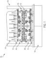
- FIG. 1 shows front view 100 of hot box 102 in press 104 according to examples of the present disclosure.
- Hot box 102 can also be termed “hot-box” or “hotbox” depending on the particular usage in the industry.
- Hot box 102 comprises lower hot box portion 108 and upper hot box portion 106.
- Lower hot box portion 108 and upper hot box portion 106 when in a closed position use a flexible heat seal 110 to close any gaps.
- Lower hot box portion 108 comprises lower housing 120 and lower heating platen 1004 that is received within lower housing 120.
- Upper hot box portion 106 comprises upper housing 122 and upper heating platen 1010 that is received within upper housing 122.
- Upper base plate 112 sometimes called an upper strongback or just strongback, is arranged on a top surface of upper hot box portion 106 and lower base plate 114, sometimes called a lower strongback or just strongback, is arranged on a bottom surface of lower hot box portion 108.
- Upper base plate 112 and lower base plate 114 provide structural reinforcement to hot box 102 and can be composed of materials, including but are not limited to, oxidation-corrosion-resistant materials such as austenitic nickel-chromium-based superalloys. Other suitable materials can be used as is known in the industry.
- Press 104 comprises lower press assembly 118 and upper press assembly 116.
- press 104 can be a superplastic forming (SPF) press or a hot-forming press.
- SPF superplastic forming
- Lower press assembly 118 and/or upper press assembly 116 can be movable along a vertical axis.
- Hot box 102 is received between lower press assembly 118 and upper press assembly 116.
- Upper hot box portion 106 is configured to receive an upper forming die portion and lower hot box portion 108 is configured to receive a lower forming die portion so that the upper forming die portion is positioned opposite the lower forming die portion.
- the lower forming die portion and the upper forming die portion are configured to apply a forming pressure to a workpiece that is received between the lower forming die portion and the upper forming die portion.
- Lower hot box portion 108 and upper hot box portion 106 are configured to form the workpiece.
- the component(s) of press 104 that apply a forming force to generate the forming pressure i.e., the tonnage of press 104) for application to the workpiece need not have a significant stroke length that accounts both for operative placement of the workpiece and removal of a formed part from press 104 and for application of the forming force.
- the component(s) of press 104 that apply a forming force to generate the forming pressure need not have a stroke length that also accounts for removal and replacement of the lower forming die portion and the upper forming die portion.
- hot box 102 can be used in a conventional press, a conventional hot-forming press, or a conventional superplastic forming press where a lower press assembly is fixed and the upper press assembly is moveable.
- lower hot box portion 108 and upper hot box portion 106 are structures that not only support the lower forming die portion and the upper forming die portion, respectively, but also may be used to heat the lower forming die portion and the upper forming die portion for operative forming of the workpiece.
- lower hot box portion 108 and upper hot box portion 106 are configured to heat the workpiece to a temperature of at least 250°C, at least 500°C, or at least 750°C, or to a temperature in the range of 250-1000°C.
- Heating the workpiece to a desired temperature enables an operator of press 104 to control the yield strength, hardness, and ductility of the workpiece, and ultimately of a part being formed from the workpiece. That is, depending on the material selection for the workpiece, a temperature or temperature range may be selected, for example, above the recrystallization temperature of the material to avoid string hardening of the material during the forming process. Moreover, heating the workpiece allows for high-strength materials to be formed at lower forming pressures than would be required in a cold-forming process.
- Illustrative, non-exclusive examples of materials that may be used for the workpiece include (but are not limited to) various aluminum and titanium alloys and steels.
- the forming pressure results from a forming force of at least 50 metric tons, at least 100 metric tons, at least 300 metric tons, at least 500 metric tons, at least 700 metric tons, at least 1000 metric tons, or at least 2000 metric tons, or in the range of 50-2250 metric tons.
- Forming pressures are selected based on material properties of the workpiece and the complexity of a part being formed from the workpiece. Moreover, higher forming pressures may provide for lower temperature requirements to result in desired material properties of the part being formed from the workpiece.
- lower press assembly 118 and upper press assembly 116 are configured to be vertically moved to a loading configuration, in which lower press assembly 118 and upper press assembly 116 are spaced-apart to receive hot box 102.
- Lower press assembly 118 and upper press assembly 116 are configured to be vertically moved to a closed configuration, in which lower press assembly 118 and upper press assembly 116 are positioned to apply the forming pressure to hot box 102, and thus to the workpiece between upper hot box portion 106 and lower hot box portion 108.
- the loading configuration provides sufficient space for an operator or platform portion, such as a robotic arm, of a platform 506, such as a part handling robot, to operatively place hot box 102 between lower press assembly 118 and upper press assembly 116.
- the closed configuration positions lower press assembly 118 and upper press assembly 116 for application of the forming pressure to the workpiece.
- the loading configuration also provides sufficient space for an operator or a platform arm, such as a robotic arm, to remove hot box 102 from lower press assembly 118 and upper press assembly 116 after press 104 has formed the part. Accordingly, in some examples, the loading configuration also may be referred to as an unloading configuration. Upper press assembly 116 is configured to be selectively locked in the closed configuration.
- Press 104 can further comprises an upper press head, at least one locking rod, and at least one rod clamp.
- Upper press assembly 116 is vertically movable relative to the upper press head. At least one locking rod is fixed to upper press assembly 116.
- At least one rod clamp is fixed to the upper press head and is configured to selectively clamp at least one locking rod to immobilize upper press assembly 116 relative to the upper press head.
- upper press assembly 116 is immobilized relative to the upper press head. Accordingly, when lower press assembly 118 applies the forming force to generate the forming pressure, upper press assembly 116 inherently applies an equal and opposite forming force for generation of the forming pressure that is applied to the workpiece for deformation thereof.
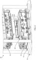
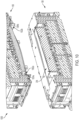
- FIG. 2 shows open front perspective view 200 of hot box 102 of FIG. 1 .
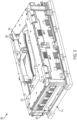
- FIG. 3 shows a front perspective view 300 of lower hot box portion 108 of FIG. 2 that is removed from press 104.
- part load/unload arm 206 holds part 204 and positions part 204 onto and off lower forming die portion 202.
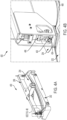
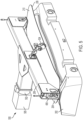
- FIG. 4A shows an isolated front perspective view 400 of part load/unload arm 206 holds part 204 and positions part 204 onto and off lower forming die portion 202 of FIG. 2 and FIG. 3 .
- FIG. 4B shows a detailed view 420 of a portion of FIG. 4A .
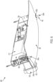
- FIG. 5 shows a reverse perspective 500 of FIG. 4A .
- FIG. 6 shows a side perspective view 600 of FIG.
- Part load/unload arm 206 can be made of a structure such as stainless steel, i.e., stainless steel 304 or 316, depending on a length of heat exposure.
- Part 204 comprises an upper surface 210 and lower surface 208.
- Part load/unload arm 206 comprises gripper 406 at each end of part load/unload arm 206.
- Removeable pin gripper 406 grips onto and holds removable securing pin 402.
- Removeable securing pin comprises lower portion securing 608a and upper portion 612a.
- Removable securing pin 402 is used for lifting and locating part 204 on a tool, such as lower forming die portion 202.
- Removable securing pin 402 comprises lower portion that has a tapered surface 604a and 604b that is clearance fitted into the lower pin receiving opening, such as lower pin receiving opening 606a of lower forming die portion 202 and lower hot box portion pin receiving opening 610a, that is reciprocally tapered to provide for removal and positioning of part 204.
- Removable securing pin 402 also comprises upper portion 612a that comprises recessed ridge 404 that allows for gripping removeable securing pin 402 and flange 602a and 602b that provides a ledge on which part 204 rests, enables lifting of part 204, and that connects a top surface of the lower pin receiving opening.
- Thermal pad 408 provides a thermal break between the lower forming die portion 202 and removable pin gripper 406 from an end effector.
- thermal pad 408 can be a ceramic pad.
- Part load/unload arm 206 comprises attach point 502 for attaching a platform 506, such as a part handling robot or other handling device. Attach point 502 can be located outside of a hot area to reduce or eliminate the need to shield whatever the loader is robot, whether the loader is a platform, a robot, or a human.
- Part load/unload arm 206 also comprises part gripper 504 to hold a portion of part 204.
- FIG. 10 shows a partial cross sectional view 1000 of upper hot box portion 106 and lower hot box portion 108 according to examples of the present disclosure. As shown in FIG. 10 , part 204 is positioned onto lower hot box portion 108.
- FIG. 11 shows a cross sectional view 1100 hot box 102 of FIG. 1 according to examples of the present disclosure.
- lower hot box portion 108 comprises lower base plate 114 and lower heating platen 1004.
- Upper hot box portion 106 comprises upper base plate 112 and upper heating platen 1010.
- Lower hot box portion 108 and upper hot box portion 106 when joined use flexible heat seal 110 to close any air gaps.
- Die 1014, or forming tool, is arranged between lower hot box portion 108 and upper hot box portion 106.
- Die 1014 comprises upper forming die portion 1016 and lower forming die portion 1018.
- the upper forming die portion 1116 is positionable above the lower forming die portion 202 and comprises an upper pin receiving opening 1002a, 1002b for receiving an upper portion 612a of the removable securing pin 402 that secures an upper surface 210 of the part 204 to be formed to the upper forming die portion 1116.
- the upper forming die portion 1116 is housed in an upper hot box portion 106, positionable above the lower hot box portion 108, wherein the upper hot box portion 106 and comprises an upper housing 122, an upper heating platen 1110, received within the upper housing 122 and configured to support the upper forming die portion 1116, and an upper hot box portion pin receiving opening 1004a, 1004b for receiving the upper portion 612a of the removable securing pin 402 that secures an upper surface 210 of the part 204 to be formed to the upper housing 122 and the upper heating platen 1110.
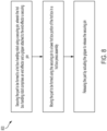
- FIG. 8 shows a method 800 for securing part to be formed in a hot box or superplastic forming (SPF) press assembly.
- Method 800 comprises securing the part to be formed to a platform, such as a part handling robot, using a securing pin, wherein the platform comprises an end effector and a gripper attached to the end effector a securing pin, as in 802.
- Method 800 continues by moving the part to be formed using the securing pin to a lower hot box portion of the hot box in a hot box press assembly, as in 804.
- Method 800 continues by releasing the part by actuating the gripper to release the securing pin, as in 806.
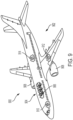
- illustrative method 800 may include specification and design of aircraft 900 and material procurement.
- component and subassembly manufacturing and system integration of aircraft 900 may take place.
- aircraft 900 may go through certification and delivery to be placed in service.
- aircraft 900 may be scheduled for routine maintenance and service. Routine maintenance and service may include modification, reconfiguration, refurbishment, etc. of one or more systems of aircraft 900.
- a system integrator may include, without limitation, any number of aircraft manufacturers and major-system subcontractors
- a third party may include, without limitation, any number of vendors, subcontractors, and suppliers
- an operator may be an airline, leasing company, military entity, service organization, and so on.
- parts for aircraft 900 produced by illustrative method 800 may include airframe 902 with a plurality of high-level systems 904 and interior 906.
- high-level systems 904 include one or more of propulsion system 908, electrical system 910, hydraulic system 912, and environmental system 914. Any number of other systems may be included.
- propulsion system 908 electrical system 910, hydraulic system 912, and environmental system 914. Any number of other systems may be included.
- an aerospace example is shown, the principles disclosed herein may be applied to other industries, such as the automotive industry. Accordingly, in addition to aircraft 900, the principles disclosed herein may apply to other vehicles, e.g., land vehicles, marine vehicles, space vehicles, etc.
- Apparatus(es) and method(s) shown or described herein may be employed during any one or more of the stages of the manufacturing and method 800.
- components or subassemblies corresponding to component and subassembly manufacturing may be fabricated or manufactured in a manner similar to components or subassemblies produced while aircraft 900 is in service.
- one or more examples of the apparatus(es), method(s), or combination thereof may be utilized during production stages, for example, by substantially expediting assembly of or reducing the cost of aircraft 900.
- one or more examples of the apparatus or method realizations, or a combination thereof may be utilized, for example and without limitation, while aircraft 900 is in service and/or during maintenance and service.
- a forming die for forming a part comprising: a lower forming die portion comprising a lower pin receiving opening for receiving a lower portion of a removable securing pin that secures a lower surface of a part to be formed to the lower forming die; and an upper forming die portion, positionable above the lower forming die portion, comprising an upper pin receiving opening for receiving an upper portion of the removable securing pin that secures an upper surface of the part to be formed to the upper forming die portion.
- Clause 2 The forming die of clause 1, wherein the lower forming die portion is housed in a lower hot box portion, wherein the lower hot box portion comprises a lower housing, a lower heating platen, received within the lower housing and configured to support the lower forming die portion, and a lower hot box portion pin receiving opening for receiving the lower portion of the removable securing pin that secures the lower surface of the part to be formed to the lower housing and the lower heating platen.
- Clause 3 The forming die of clause 1 or clause 2, wherein the upper forming die portion is housed in an upper hot box portion, positionable above the lower hot box portion, wherein the upper hot box portion comprises an upper housing, an upper heating platen, received within the upper housing and configured to support the upper forming die portion, and an upper hot box portion pin receiving opening for receiving the upper portion of the removable securing pin that secures an upper surface of the part to be formed to the upper housing and the upper heating platen.
- Clause 4 The forming die of any of clauses 1-3, further comprising the removable securing pin.
- Clause 5 The forming die of any of clauses 1-4, wherein the lower portion of the removable securing pin comprises a tapered surface that is clearance fit into the lower pin receiving opening that is reciprocally tapered to provide for removal and positioning of the part.
- Clause 6 The forming die of any of clauses 1-5, wherein the upper portion of the removable securing pin comprises a flange that provides a ledge on which the part rests, enables lifting of the part, and that connects a top surface of the lower pin receiving opening.
- Clause 7 The forming die of any of clauses 1-6, wherein the upper portion of the removable securing pin comprises a recessed ridge that allows for gripping the removeable securing pin.
- Clause 8 The forming die of any of clauses 1-7, further comprising a thermal pad that provides a thermal break between the lower forming die portion and a gripper from an end effector.
- Clause 9 The forming die of any of clauses 1-8, wherein the lower hot box portion and the upper hot box portion are removable from a press assembly.
- a hot box for hot forming a part comprising: a lower hot box portion, comprising: a lower housing, a lower heating platen, received within the lower housing and configured to support a lower forming die portion, and a lower pin receiving opening for receiving a lower portion of a removable securing pin that secures a lower surface of a part to be formed to the lower housing and the lower heating platen and an upper hot box portion, positionable above the lower hot box portion and comprising: an upper housing, an upper heating platen, received within the upper housing and configured to support an upper forming die portion, and a upper pin receiving opening for receiving an upper portion of the removable securing pin that secures an upper surface of the part to be formed to the upper housing and the upper heating platen.
- Clause 11 The hot box of clause 10, further comprising the removable securing pin.
- Clause 12 The hot box of clause 10 or clause 11, wherein the lower portion of the removable securing pin comprises a tapered surface that is clearance fit into the lower pin receiving opening that is reciprocally tapered to provide for removal and positioning of the part.
- Clause 13 The hot box of any of clauses 10-12, wherein the upper portion of the removable securing pin comprises a flange that provides a ledge on which the part rests, enables lifting of the part, and that connects a top surface of the lower pin receiving opening.
- Clause 14 The hot box of any of clauses 10-13, wherein the upper portion of the removable securing pin comprises a recessed ridge that allows for gripping the removeable securing pin.
- Clause 15 The hot box of any of clauses 10-14, further comprising a thermal pad that provides a thermal break between the lower forming die portion and a gripper from an end effector.
- Clause 16 The hot box of any of clauses 10-15, wherein the lower hot box portion and the upper hot box portion are removable from a press assembly.
- a platform comprising: an end effector; and a gripper attached to the end effector that grips a securing pin that secures a part to a lower hot box portion of a hot box, wherein the securing pin comprises a tapered lower body portion, a flange arranged between the lower body portion and an upper body portion, and a recessed ridge arranged above the flange that allows the gripper to hold the securing pin.
- Clause 18 The platform of clause 17, wherein the system comprises a part handling robot, a user-controlled platform, a computer-controlled platform, or a part-handling frame.
- a part securing pin comprising: a tapered lower body portion; an upper body portion; a flange arranged between the lower body portion and the upper body portion; and a recessed ridge arranged above the flange that allows a gripper to hold the hot box securing pin.
- a method for securing part to be formed in a hot box or superplastic forming (SPF) press assembly comprising: securing the part to be formed to a platform using a securing pin, wherein the platform comprises an end effector and a gripper attached to the end effector a securing pin; moving the part to be formed using the securing pin to a lower hot box portion of the hot box in a hot box press assembly; and releasing the part by actuating the gripper to release the securing pin.
- SPF superplastic forming
- a part securing pin comprising: a lower body portion; and an upper body portion.
- Clause 22 The part securing pin of clause 21, wherein the lower body portion is tapered.
- Clause 23 The part securing pin of clause 21 or 22, further comprising a recessed ridge arranged above the flange that allows for gripping the removeable securing pin.
- Clause 24 The part securing pin of clause 23, further comprising a flange arranged between the lower body portion and the upper body portion.
- a forming die for forming a part comprising: the part securing pin of any of clauses 21 to 24; a lower forming die portion comprising a lower pin receiving opening configured to receive removably the lower portion of the securing pin; and an upper forming die portion, positionable above the lower forming die portion, comprising an upper pin receiving opening for receiving removably the upper portion of the securing pin.
- Clause 26 The forming die of clause 25, wherein the lower forming die portion is housed in a lower hot box portion, wherein the lower hot box portion comprises a lower housing, a lower heating platen, received within the lower housing and configured to support the lower forming die portion, and a lower hot box portion pin receiving opening for receiving the lower portion of the removable securing pin.
- Clause 27 The forming die of clause 25 or 26, wherein the upper forming die portion is housed in an upper hot box portion, positionable above the lower hot box portion, wherein the upper hot box portion comprises an upper housing, an upper heating platen, received within the upper housing and configured to support the upper forming die portion, and an upper hot box portion pin receiving opening for receiving the upper portion of the removable securing pin.
- Clause 28 The forming die of clause 27 when dependent upon clause 26, wherein the lower hot box portion and the upper hot box portion are removable from a press assembly.
- Clause 29 The forming die of any of clauses 25 to 28 when dependent upon clause 22, wherein the lower portion of the removable securing pin comprises a tapered surface that is a clearance fit into the lower pin receiving opening that is reciprocally tapered to provide for removal and positioning of the part.
- Clause 30 The forming die of any of clauses 25 to 29 when dependent upon clause 24, wherein the upper portion of the removable securing pin comprises the flange that provides a ledge on which the part may rest, enables lifting of the part, and that connects to a top surface of the lower pin receiving opening.
- Clause 31 An apparatus comprising: the forming die of any of clauses 25 to 30; and a part to be formed; wherein: the lower portion of the removable securing pin secures a lower surface of a part to be formed to the lower forming die; and the upper portion of the removable securing pin secures an upper surface of the part to be formed to the upper forming die portion.
- Clause 32 An apparatus comprising: the forming die of any of clauses 25 to 30 when dependent upon clause 23; and a platform comprising an end effector and a gripper attached to the end effector configured to grip the recessed ridge of the securing pin.
- Clause 33 The apparatus of clause 32, wherein the platform comprises a part handling robot, a user-controlled platform, a computer-controlled platform, or a part-handling frame.
- Clause 34 The apparatus of clause 32 or 33, further comprising a thermal pad that provides a thermal break between the lower forming die portion and the gripper.
- Clause 35 The apparatus of any of clauses 32 to 34, further comprising a part to be formed and wherein the lower portion of the removable securing pin secures a lower surface of a part to be formed to the lower forming die and the upper portion of the removable securing pin secures an upper surface of the part to be formed to the upper forming die portion.
- Clause 36 A method for securing part to be formed in the apparatus of any of clauses 32 to 35, the method comprising: securing the part to be formed to the platform using the securing pin; moving the part to be formed using the securing pin to the lower forming die portion; and releasing the part by actuating the gripper to release the securing pin.
- Clause 37 The method of clause 36, further comprising gripping the securing pin with the gripper, and wherein moving the part to be formed comprises using the end effector to move the gripper (504) thereby moving the securing pin (402) and part (204).
Landscapes
- Engineering & Computer Science (AREA)
- Mechanical Engineering (AREA)
- Physics & Mathematics (AREA)
- Thermal Sciences (AREA)
- Fluid Mechanics (AREA)
- Shaping Metal By Deep-Drawing, Or The Like (AREA)
- Manipulator (AREA)
- Mounting, Exchange, And Manufacturing Of Dies (AREA)
- Molds, Cores, And Manufacturing Methods Thereof (AREA)
- Extrusion Of Metal (AREA)
- Forging (AREA)
Applications Claiming Priority (1)
| Application Number | Priority Date | Filing Date | Title |
|---|---|---|---|
| US18/302,225 US20240351089A1 (en) | 2023-04-18 | 2023-04-18 | Flanged and tapered pin for method to automate part loading and unloading |
Publications (2)
| Publication Number | Publication Date |
|---|---|
| EP4450181A2 true EP4450181A2 (de) | 2024-10-23 |
| EP4450181A3 EP4450181A3 (de) | 2024-12-18 |
Family
ID=90059413
Family Applications (1)
| Application Number | Title | Priority Date | Filing Date |
|---|---|---|---|
| EP24159598.2A Pending EP4450181A3 (de) | 2023-04-18 | 2024-02-26 | Geflanschter und konischer stift für ein verfahren zur automatisierung der teilladung und -entladung |
Country Status (4)
| Country | Link |
|---|---|
| US (1) | US20240351089A1 (de) |
| EP (1) | EP4450181A3 (de) |
| JP (1) | JP2024154365A (de) |
| CN (1) | CN118810108A (de) |
Family Cites Families (9)
| Publication number | Priority date | Publication date | Assignee | Title |
|---|---|---|---|---|
| US3871095A (en) * | 1971-08-26 | 1975-03-18 | Citizen Watch Co Ltd | Process for the manufacture of hair spring collet |
| US6322119B1 (en) * | 1999-07-09 | 2001-11-27 | Semitool, Inc. | Robots for microelectronic workpiece handling |
| JP2001321864A (ja) * | 2000-05-09 | 2001-11-20 | Fuji Heavy Ind Ltd | プレス金型 |
| JP4555839B2 (ja) * | 2007-03-13 | 2010-10-06 | 豊田鉄工株式会社 | 熱間プレス加工における板状ワークの位置決め構造 |
| CN104801616A (zh) * | 2015-05-29 | 2015-07-29 | 东莞豪顺家具有限公司 | 一种活动台阶式定位的模具 |
| FR3043923A1 (fr) * | 2015-11-25 | 2017-05-26 | Peugeot Citroen Automobiles Sa | Dispositif de pilotage et emboutissage d’une piece |
| GB201609988D0 (en) * | 2016-06-08 | 2016-07-20 | Rolls Royce Plc | Datum positioning in dies |
| US11253898B2 (en) * | 2018-10-18 | 2022-02-22 | The Boeing Company | Hot-forming presses and methods of hot-forming workpieces |
| CN113198910B (zh) * | 2021-05-13 | 2024-07-26 | 成都宏明双新科技股份有限公司 | 一种模内快速控制定位钉升降的模具 |
-
2023
- 2023-04-18 US US18/302,225 patent/US20240351089A1/en active Pending
-
2024
- 2024-01-30 JP JP2024011800A patent/JP2024154365A/ja active Pending
- 2024-02-22 CN CN202410197477.7A patent/CN118810108A/zh active Pending
- 2024-02-26 EP EP24159598.2A patent/EP4450181A3/de active Pending
Also Published As
| Publication number | Publication date |
|---|---|
| US20240351089A1 (en) | 2024-10-24 |
| CN118810108A (zh) | 2024-10-22 |
| EP4450181A3 (de) | 2024-12-18 |
| JP2024154365A (ja) | 2024-10-30 |
Similar Documents
| Publication | Publication Date | Title |
|---|---|---|
| JP6602546B2 (ja) | 組立製造のためのシステム及び方法 | |
| US9364926B2 (en) | System and method of assembling components | |
| EP3900853B1 (de) | Warmkasten für warmformpressen und verfahren zum warmformen von werkstücken | |
| US5265317A (en) | Geometry station | |
| US11364623B2 (en) | Component assembly system | |
| US20040093731A1 (en) | Adjustable system and method for supporting and joining structural members | |
| EP1764291B1 (de) | Rahmenanordnung für ein Kraftfahrzeug | |
| US6629354B1 (en) | Apparatus for immobilizing a frame structure in its free state to establish a net datum position thereof | |
| US20240262638A1 (en) | Pick-and-place system and method | |
| EP1354647B1 (de) | Verfahren und Vorrichtung zum superplastischen Verformen von Werkstücken aus mehreren Platten | |
| EP4450181A2 (de) | Geflanschter und konischer stift für ein verfahren zur automatisierung der teilladung und -entladung | |
| US7284402B2 (en) | System and process for superplastic forming | |
| JPH1190641A (ja) | 組立ラインにおけるワークハンドリング方法及び溶接方法 | |
| BR102024002059A2 (pt) | Pino flangeado e cônico para método para automatizar carregamento e descarregamento de peças | |
| EP4353378A1 (de) | Hotbox-austauschfähigkeit und verfahren dafür | |
| US20090179013A1 (en) | Laser welding process | |
| CN214263757U (zh) | 一种自冲铆工作站 | |
| Nurhadi et al. | Rancang Bangun dan Analisis Jig Welding Pengelasan Siku Sebagai Alat Bantu Praktikum Produksi Jig & Fixture di Politeknik STMI Jakarta | |
| US20250347599A1 (en) | Modular Material Testing Apparatus for Material Testing of a Specimen | |
| Jonsson et al. | Coordinate controlled fixturing for affordable reconfigurable tooling | |
| EP4119446B1 (de) | Verfahren zur montage von rahmen in einer flugzeughülle | |
| US20040069038A1 (en) | Method of stretch forming an aluminum metal sheet and handling equipment for doing the same | |
| EP4446099A1 (de) | Nachgiebige prägewerkzeuge, systeme und verfahren zur stanzformung eines werkstücks | |
| EP4177170A1 (de) | Systeme und verfahren zur unterstützung eines werkstücks in einer fertigungsumgebung | |
| GB2433458A (en) | System and proces for superplastic forming |
Legal Events
| Date | Code | Title | Description |
|---|---|---|---|
| PUAI | Public reference made under article 153(3) epc to a published international application that has entered the european phase |
Free format text: ORIGINAL CODE: 0009012 |
|
| STAA | Information on the status of an ep patent application or granted ep patent |
Free format text: STATUS: THE APPLICATION HAS BEEN PUBLISHED |
|
| AK | Designated contracting states |
Kind code of ref document: A2 Designated state(s): AL AT BE BG CH CY CZ DE DK EE ES FI FR GB GR HR HU IE IS IT LI LT LU LV MC ME MK MT NL NO PL PT RO RS SE SI SK SM TR |
|
| PUAL | Search report despatched |
Free format text: ORIGINAL CODE: 0009013 |
|
| AK | Designated contracting states |
Kind code of ref document: A3 Designated state(s): AL AT BE BG CH CY CZ DE DK EE ES FI FR GB GR HR HU IE IS IT LI LT LU LV MC ME MK MT NL NO PL PT RO RS SE SI SK SM TR |
|
| RIC1 | Information provided on ipc code assigned before grant |
Ipc: B21D 43/10 20060101ALI20241108BHEP Ipc: B21D 43/11 20060101ALI20241108BHEP Ipc: B21D 43/06 20060101ALI20241108BHEP Ipc: B21D 43/00 20060101ALI20241108BHEP Ipc: B21D 37/16 20060101ALI20241108BHEP Ipc: B21D 37/12 20060101ALI20241108BHEP Ipc: B21D 22/20 20060101ALI20241108BHEP Ipc: B21D 22/02 20060101AFI20241108BHEP |
|
| STAA | Information on the status of an ep patent application or granted ep patent |
Free format text: STATUS: REQUEST FOR EXAMINATION WAS MADE |
|
| 17P | Request for examination filed |
Effective date: 20250502 |