EP4450022A1 - Intraoraler scanner - Google Patents
Intraoraler scanner Download PDFInfo
- Publication number
- EP4450022A1 EP4450022A1 EP22907966.0A EP22907966A EP4450022A1 EP 4450022 A1 EP4450022 A1 EP 4450022A1 EP 22907966 A EP22907966 A EP 22907966A EP 4450022 A1 EP4450022 A1 EP 4450022A1
- Authority
- EP
- European Patent Office
- Prior art keywords
- reflector
- optical system
- reflective surfaces
- light
- light source
- Prior art date
- Legal status (The legal status is an assumption and is not a legal conclusion. Google has not performed a legal analysis and makes no representation as to the accuracy of the status listed.)
- Pending
Links
Images


Classifications
-
- A—HUMAN NECESSITIES
- A61—MEDICAL OR VETERINARY SCIENCE; HYGIENE
- A61B—DIAGNOSIS; SURGERY; IDENTIFICATION
- A61B1/00—Instruments for performing medical examinations of the interior of cavities or tubes of the body by visual or photographical inspection, e.g. endoscopes; Illuminating arrangements therefor
- A61B1/24—Instruments for performing medical examinations of the interior of cavities or tubes of the body by visual or photographical inspection, e.g. endoscopes; Illuminating arrangements therefor for the mouth, i.e. stomatoscopes, e.g. with tongue depressors; Instruments for opening or keeping open the mouth
-
- A—HUMAN NECESSITIES
- A61—MEDICAL OR VETERINARY SCIENCE; HYGIENE
- A61B—DIAGNOSIS; SURGERY; IDENTIFICATION
- A61B1/00—Instruments for performing medical examinations of the interior of cavities or tubes of the body by visual or photographical inspection, e.g. endoscopes; Illuminating arrangements therefor
- A61B1/00064—Constructional details of the endoscope body
- A61B1/00071—Insertion part of the endoscope body
- A61B1/0008—Insertion part of the endoscope body characterised by distal tip features
- A61B1/00096—Optical elements
-
- A—HUMAN NECESSITIES
- A61—MEDICAL OR VETERINARY SCIENCE; HYGIENE
- A61B—DIAGNOSIS; SURGERY; IDENTIFICATION
- A61B1/00—Instruments for performing medical examinations of the interior of cavities or tubes of the body by visual or photographical inspection, e.g. endoscopes; Illuminating arrangements therefor
- A61B1/00163—Optical arrangements
- A61B1/00172—Optical arrangements with means for scanning
-
- A—HUMAN NECESSITIES
- A61—MEDICAL OR VETERINARY SCIENCE; HYGIENE
- A61B—DIAGNOSIS; SURGERY; IDENTIFICATION
- A61B1/00—Instruments for performing medical examinations of the interior of cavities or tubes of the body by visual or photographical inspection, e.g. endoscopes; Illuminating arrangements therefor
- A61B1/00163—Optical arrangements
- A61B1/00174—Optical arrangements characterised by the viewing angles
- A61B1/00177—Optical arrangements characterised by the viewing angles for 90 degrees side-viewing
-
- A—HUMAN NECESSITIES
- A61—MEDICAL OR VETERINARY SCIENCE; HYGIENE
- A61B—DIAGNOSIS; SURGERY; IDENTIFICATION
- A61B1/00—Instruments for performing medical examinations of the interior of cavities or tubes of the body by visual or photographical inspection, e.g. endoscopes; Illuminating arrangements therefor
- A61B1/00163—Optical arrangements
- A61B1/00193—Optical arrangements adapted for stereoscopic vision
-
- A—HUMAN NECESSITIES
- A61—MEDICAL OR VETERINARY SCIENCE; HYGIENE
- A61B—DIAGNOSIS; SURGERY; IDENTIFICATION
- A61B1/00—Instruments for performing medical examinations of the interior of cavities or tubes of the body by visual or photographical inspection, e.g. endoscopes; Illuminating arrangements therefor
- A61B1/00163—Optical arrangements
- A61B1/00194—Optical arrangements adapted for three-dimensional imaging
-
- A—HUMAN NECESSITIES
- A61—MEDICAL OR VETERINARY SCIENCE; HYGIENE
- A61B—DIAGNOSIS; SURGERY; IDENTIFICATION
- A61B1/00—Instruments for performing medical examinations of the interior of cavities or tubes of the body by visual or photographical inspection, e.g. endoscopes; Illuminating arrangements therefor
- A61B1/06—Instruments for performing medical examinations of the interior of cavities or tubes of the body by visual or photographical inspection, e.g. endoscopes; Illuminating arrangements therefor with illuminating arrangements
- A61B1/0605—Instruments for performing medical examinations of the interior of cavities or tubes of the body by visual or photographical inspection, e.g. endoscopes; Illuminating arrangements therefor with illuminating arrangements for spatially modulated illumination
-
- A—HUMAN NECESSITIES
- A61—MEDICAL OR VETERINARY SCIENCE; HYGIENE
- A61B—DIAGNOSIS; SURGERY; IDENTIFICATION
- A61B1/00—Instruments for performing medical examinations of the interior of cavities or tubes of the body by visual or photographical inspection, e.g. endoscopes; Illuminating arrangements therefor
- A61B1/06—Instruments for performing medical examinations of the interior of cavities or tubes of the body by visual or photographical inspection, e.g. endoscopes; Illuminating arrangements therefor with illuminating arrangements
- A61B1/0615—Instruments for performing medical examinations of the interior of cavities or tubes of the body by visual or photographical inspection, e.g. endoscopes; Illuminating arrangements therefor with illuminating arrangements for radial illumination
-
- A—HUMAN NECESSITIES
- A61—MEDICAL OR VETERINARY SCIENCE; HYGIENE
- A61B—DIAGNOSIS; SURGERY; IDENTIFICATION
- A61B1/00—Instruments for performing medical examinations of the interior of cavities or tubes of the body by visual or photographical inspection, e.g. endoscopes; Illuminating arrangements therefor
- A61B1/06—Instruments for performing medical examinations of the interior of cavities or tubes of the body by visual or photographical inspection, e.g. endoscopes; Illuminating arrangements therefor with illuminating arrangements
- A61B1/0623—Instruments for performing medical examinations of the interior of cavities or tubes of the body by visual or photographical inspection, e.g. endoscopes; Illuminating arrangements therefor with illuminating arrangements for off-axis illumination
-
- A—HUMAN NECESSITIES
- A61—MEDICAL OR VETERINARY SCIENCE; HYGIENE
- A61B—DIAGNOSIS; SURGERY; IDENTIFICATION
- A61B1/00—Instruments for performing medical examinations of the interior of cavities or tubes of the body by visual or photographical inspection, e.g. endoscopes; Illuminating arrangements therefor
- A61B1/24—Instruments for performing medical examinations of the interior of cavities or tubes of the body by visual or photographical inspection, e.g. endoscopes; Illuminating arrangements therefor for the mouth, i.e. stomatoscopes, e.g. with tongue depressors; Instruments for opening or keeping open the mouth
- A61B1/247—Instruments for performing medical examinations of the interior of cavities or tubes of the body by visual or photographical inspection, e.g. endoscopes; Illuminating arrangements therefor for the mouth, i.e. stomatoscopes, e.g. with tongue depressors; Instruments for opening or keeping open the mouth with means for viewing areas outside the direct line of sight, e.g. dentists' mirrors
-
- A—HUMAN NECESSITIES
- A61—MEDICAL OR VETERINARY SCIENCE; HYGIENE
- A61B—DIAGNOSIS; SURGERY; IDENTIFICATION
- A61B5/00—Measuring for diagnostic purposes; Identification of persons
- A61B5/0059—Measuring for diagnostic purposes; Identification of persons using light, e.g. diagnosis by transillumination, diascopy, fluorescence
- A61B5/0062—Arrangements for scanning
-
- A—HUMAN NECESSITIES
- A61—MEDICAL OR VETERINARY SCIENCE; HYGIENE
- A61B—DIAGNOSIS; SURGERY; IDENTIFICATION
- A61B5/00—Measuring for diagnostic purposes; Identification of persons
- A61B5/0059—Measuring for diagnostic purposes; Identification of persons using light, e.g. diagnosis by transillumination, diascopy, fluorescence
- A61B5/0082—Measuring for diagnostic purposes; Identification of persons using light, e.g. diagnosis by transillumination, diascopy, fluorescence adapted for particular medical purposes
- A61B5/0088—Measuring for diagnostic purposes; Identification of persons using light, e.g. diagnosis by transillumination, diascopy, fluorescence adapted for particular medical purposes for oral or dental tissue
-
- A—HUMAN NECESSITIES
- A61—MEDICAL OR VETERINARY SCIENCE; HYGIENE
- A61C—DENTISTRY; APPARATUS OR METHODS FOR ORAL OR DENTAL HYGIENE
- A61C19/00—Dental auxiliary appliances
- A61C19/04—Measuring instruments specially adapted for dentistry
-
- A—HUMAN NECESSITIES
- A61—MEDICAL OR VETERINARY SCIENCE; HYGIENE
- A61C—DENTISTRY; APPARATUS OR METHODS FOR ORAL OR DENTAL HYGIENE
- A61C9/00—Impression cups, i.e. impression trays; Impression methods
- A61C9/004—Means or methods for taking digitized impressions
- A61C9/0046—Data acquisition means or methods
- A61C9/0053—Optical means or methods, e.g. scanning the teeth by a laser or light beam
- A61C9/006—Optical means or methods, e.g. scanning the teeth by a laser or light beam projecting one or more stripes or patterns on the teeth
Definitions
- the present disclosure relates to an intraoral scanner, and more particularly, to an intraoral scanner configured to obtain a 3D image of an oral cavity.
- an impression-taking procedure is performed in a process of diagnosis or treatment of a dental patient.
- Impression taking is a necessary clinical procedure in establishing a diagnosis and treatment plan for a patient by reflecting conditions of teeth and tissue in an oral cavity in an impression material.
- the number of cases of using a digital impression in which an oral cavity or an impression body is scanned and converted into digital data without using an impression material in impression taking has increased.
- development of technology related to intraoral scanners has been actively carried out.
- An intraoral scanner is a device or system inserted into an oral cavity of a dental patient to scan a 3D structure of teeth in a non-contact manner.
- intraoral scanners capture 2D image data of an oral cavity and perform 3D modeling of an oral cavity structure based on the 2D image data.
- the range of application of intraoral scanners having such functions has expanded among clinical applications, and the intraoral scanners may also be used in fabricating an implant, an orthodontic appliance, and the like in addition to being used in treatment for tooth restoration.
- impression accuracy is important for successful dental treatment.
- a digital impression using an intraoral scanner does not have a problem of deformation due to contraction, expansion, or the like of an impression material and thus has higher impression accuracy compared to a traditional impression-taking method.
- an intraoral scanner for an intraoral scanner to be continuously used as a tool for sophisticated dental treatment, there is a need to enhance scanning accuracy.
- an intraoral scanner since an intraoral scanner is used by being inserted into an oral cavity of a dental patient in a non-contact manner, it is preferable for the intraoral scanner to have a structure that makes a patient feel comfortable during use of the intraoral scanner.
- Embodiments disclosed in the present specification provide an intraoral scanner having a plurality of optical systems disposed therein to have a structure suitable to be used by being inserted into an oral cavity of a dental patient in a non-contact manner.
- an intraoral scanner including: a case having an opening part formed at one end thereof; a light source part disposed at the other end of the case and configured to emit light; a first optical system including a first reflector configured to reflect the light emitted from the light source part and a second reflector disposed apart from the first reflector and configured to reflect the light reflected by the first reflector toward the opening part; a second optical system disposed in the opening part and configured to reflect the light reflected from the first optical system toward a subject and reflect light reflected from the subject toward the second reflector; a third optical system disposed to be adjacent to a back surface in an opposite direction of a reflective surface of the second reflector and configured to reflect the light reflected from the second optical system; and an image sensor part configured to detect the light reflected from the third optical system.
- the third optical system may include a fourth reflector configured to reflect the light reflected from the second optical system and a fifth reflector configured to reflect the light reflected by the fourth reflector toward the image sensor part.
- the fourth reflector may include two reflective surfaces configured so that a dihedral angle between the reflective surfaces forms a minor angle
- the fifth reflector may include two reflective surfaces configured so that a dihedral angle between the reflective surfaces forms a major angle
- positions and directions of the two reflective surfaces of the fifth reflector may be set so that two images of the subject each reflected by the two reflective surfaces of the fifth reflector and detected by the image sensor part do not overlap with each other, and each of the images is entirely visible.
- a gap may be formed at a central portion of the fourth reflector, light emitted from the fifth reflector may be configured to pass through the gap and reach the image sensor part, and the two reflective surfaces of the fifth reflector may be connected to each other at one side edge of each reflective surface.
- the first optical system may be configured as a rhomboid prism including the first reflector and the second reflector.
- the light source part may include a first light source part and a second light source part that emit light
- the first light source part and the second light source part may be disposed at an upper portion and a lower portion, respectively, from the image sensor part
- the first optical system may further include a third reflector disposed at a position symmetrical to the first reflector about the second reflector and configured to reflect the light emitted from the second light source part
- the second reflector may include two reflective surfaces each configured to reflect one of the light reflected by the first reflector and the light reflected by the third reflector toward the opening part, and a dihedral angle between the reflective surfaces of the second reflector may be configured to form a major angle.
- the light source part may be configured to emit patterned light or structured light.
- the image sensor part may be configured to obtain two stereo images from an image of the light reflected from the third optical system.
- the fourth reflector may include two pairs of reflective surfaces configured so that a dihedral angle between each pair of reflective surfaces forms a minor angle
- the fifth reflector may include two reflective surfaces configured so that a dihedral angle between the reflective surfaces forms a major angle
- positions and directions of the two reflective surfaces of the fifth reflector may be set so that four images of the subject each reflected by the two reflective surfaces of the fifth reflector and detected by the image sensor part do not overlap with each other, and each of the images is entirely visible
- a gap may be formed at central portions of each pair of reflective surfaces of the fourth reflector
- the light emitted from the fifth reflector may be configured to pass through the gap and reach the image sensor part
- the two reflective surfaces of the fifth reflector may be connected to each other at one side edge of each reflective surface
- the image sensor part may be configured to obtain four stereo images from an image of the light reflected from the third optical system.
- the optical systems can be densely arranged at optimal positions inside the case.
- an intraoral scanner having a small volume by arranging a plurality of optical systems in a dense structure inside a case, during use of the intraoral scanner, it is not only easy to insert the intraoral scanner into an oral cavity of a dental patient but also easy to move or change a direction of the intraoral scanner in the oral cavity, and thus dental scanning can be precisely performed.
- a singular expression includes a plural expression unless the context clearly indicates singularity. Also, a plural expression includes a singular expression unless the context clearly indicates plurality.
- the upper part of a drawing may be referred to as “upper portion” or “upper side” of a configuration illustrated in the drawing, and the lower part of the drawing may be referred to as “lower portion” or “lower side” of the configuration
- a portion between the upper portion and the lower portion of the configuration illustrated in the drawing or a remaining portion excluding the upper portion and the lower portion may be referred to as “side portion” or “side surface” of the configuration.
- the relative terms such as “upper portion” and “upper side” may be used to describe the relationship between configurations illustrated in the drawings, and the present disclosure is not limited by the terms.
- inner side a direction toward an inner space of one structure
- outer side a direction protruding to an open outer space
- inner side and outer side may be used to describe the relationship between configurations illustrated in the drawings, and the present disclosure is not limited by the terms.
- a and/or B refers to A, B, or A and B.
- modules refer to software or hardware components, and a “module” or “part” performs a certain role.
- a “module” or “part” may be configured to be present in addressable storage media or configured to replay one or more processors. Therefore, as one example, a “module” or “part” may include at least one of components such as software components, object-oriented software components, class components, and task components, processes, functions, attributes, procedures, subroutines, program code segments, drivers, firmware, micro codes, circuits, data, databases, data structures, tables, arrays, or variables.
- the components and the "modules” or “parts” and functions provided therein may be combined into a smaller number of components and “modules” or “parts” or may be further separated into a larger number of components and “modules” or “parts.”
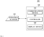
- FIG. 1 is a block diagram illustrating a configuration of an intraoral scanning system 100 in which an intraoral scanner 110 according to one embodiment of the present disclosure is connected to an intraoral 3D modeling and visualization server 120.
- the intraoral scanning system 100 may include the intraoral scanner 110 that can scan a 3D structure of an oral cavity of a dental patient and the intraoral 3D modeling and visualization server 120 connected to the intraoral scanner 110.
- the intraoral scanner 110 may be inserted into an oral cavity of a dental patient by a medical worker in a dental clinic to scan teeth in a non-contact manner and capture a plurality of pieces of 2D image data. Also, the intraoral scanner 110 may send the plurality of pieces of captured 2D image data to the 3D modeling and visualization server 120 or may perform 3D oral cavity structure modeling based on the 2D image data by itself.
- the intraoral scanner 110 may be connected to the 3D modeling and visualization server 120 through a network configured to be able to communicate via a wire or wirelessly.
- the network may be configured with a wired network such as an electric connection line such as a copper cable, Ethernet, a wired home network (power line communication), a phone line communication device, and RS-serial communication, a wireless network such as a mobile network, a wireless local area network (WLAN), Wi-Fi, Bluetooth, and ZigBee, or a combination thereof.
- a wired network such as an electric connection line such as a copper cable, Ethernet, a wired home network (power line communication), a phone line communication device, and RS-serial communication
- a wireless network such as a mobile network, a wireless local area network (WLAN), Wi-Fi, Bluetooth, and ZigBee, or a combination thereof.
- the intraoral scanner 110 may transmit and receive information and/or data such as 2D image data and 3D oral cavity structure model data to and from the 3D modeling and visualization server 120.
- the intraoral scanner 110 and the 3D modeling and visualization server 120 may be configured to be physically separated as illustrated, but the present disclosure is not limited thereto.
- the intraoral scanner 110 and the 3D modeling and visualization server 120 may be integrally configured in a single computing device.
- the 3D modeling and visualization server 120 may perform 3D oral cavity structure modeling based on at least two pieces of 2D image data or stereo images obtained from the intraoral scanner 110.
- the 3D modeling and visualization server 120 may correspond to a computing device including a processor that can perform image processing and 3D modeling (for example, a central processing unit (CPU), a graphics processing unit (GPU), an application processor (AP), a neutral processing unit (NPU), etc.) and a memory that can store 2D image data and 3D oral cavity structure model data.
- the 3D modeling and visualization server 120 may include a communication device 122, a controller 124, and a display device 126 as illustrated.
- the communication device 122 may be configured to transmit and receive information and/or data to and from the intraoral scanner 110. Specifically, the communication device 122 may transmit a command signal of the controller 124 to the intraoral scanner 110 and may receive image information of a target oral cavity structure from the intraoral scanner 110.
- the controller 124 may control the intraoral scanner 110 to capture an image of the target oral cavity structure. Specifically, the controller 124 may control at least one or more light source parts (for example, 220 in FIG. 2 ) installed inside the intraoral scanner 110 to emit light toward at least one of a plurality of optical systems. Also, the controller 124 may control an image sensor part (for example, 270 in FIG. 2 ) installed inside the intraoral scanner 110 to detect light reflected by at least one of the plurality of optical systems. The controller 124 may control the image sensor part to obtain at least two or more stereo images from an image of the detected light. The controller 124 may control the display device 126 to display the two or more stereo images received from the intraoral scanner 110. Alternatively or additionally, the controller 124 may control 3D oral cavity structure model data calculated based on the two or more stereo images to be visualized and displayed on the display device 126.
- the controller 124 may control 3D oral cavity structure model data calculated based on the two or more stereo images to be visualized and displayed on the display device 126
- the display device 126 may display information and/or data received from the intraoral scanner 110 or the controller 124.
- data displayed on the display device 126 may include two stereo images or 3D oral cavity structure model images.
- the display device 126 may include a display panel device such as a light emitting diode (LED) display, an organic light emitting diode (OLED) display, a liquid crystal display (LCD), or a touch display.
- LED light emitting diode
- OLED organic light emitting diode
- LCD liquid crystal display
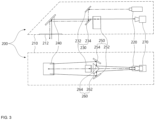
- FIG. 2 is a see-through perspective view of an intraoral scanner 200 according to one embodiment of the present disclosure.
- the intraoral scanner 200 may include a case 210, a light source part 220, a first optical system 230, a second optical system 240, third optical systems 250 and 260, and an image sensor part 270.
- the case 210 may be configured to form an exterior of the intraoral scanner 200 and accommodate the light source part 220, the first optical system 230, the second optical system 240, the third optical systems 250 and 260, and the image sensor part 270 therein.
- the case 210 may have the shape of a trapezoidal box that substantially extends in any one longitudinal direction, but the present disclosure is not limited thereto.
- the case 210 may have a rectangular parallelepiped shape, a cylindrical shape, a streamlined shape, or any other shape suitable for insertion into an oral cavity.
- An opening part 212 may be formed at one end of the case 210.
- the opening part 212 may include an opening formed at one end of the case 210.
- the opening of the opening part 212 may be configured to allow light generated or reflected inside the case 210 to be emitted to the outside and external light to be introduced into the case 210.
- the opening part 212 may be configured to be positioned at the innermost side of an oral cavity when the intraoral scanner 200 is inserted into the oral cavity.
- the light source part 220 may be configured to emit light toward the opening part 212, the first optical system 230, or the second optical system 240.
- light emitted from the light source part 220 may correspond to patterned light or structured light.
- the light may have a linear pattern, a dot pattern, or any other pattern.
- patterned light is emitted to a subject 280 such as teeth in an oral cavity, deformation of the corresponding pattern may occur according to a 3D structure of a surface of the subject 280. Therefore, the 3D structure of the subject 280 may be identified and modeled based on the deformation of the pattern projected on the surface of the subject 280 or information on changes of positions of feature points.
- the light source part 220 may be disposed at the other end of the case 210. Specifically, the light source part 220 may be disposed to be accommodated at the other end inside the case 210 that faces one end of the case 210 at which the opening part 212 or the second optical system 240 is formed. For example, the light source part 220 may be disposed to be fixed to an upper portion of the other end inside the case 210. In one embodiment, the light source part 220 may include a first light source part (for example, 822 in FIG. 8 ) and a second light source part (for example, 824 in FIG. 8 ).
- the first light source part and the second light source part may be disposed at the other end of the case together with the image sensor part 270 and may be disposed to be respectively fixed to the upper portion and lower portion of the other end inside the case 210 around the image sensor part.
- the configuration of the intraoral scanner 200 including the two light source parts will be described in detail below with reference to FIG. 8 .
- the light source part 220 may be disposed at one side end of the case 210, but the present disclosure is not limited thereto.
- the light source part 220 may be disposed at any intermediate point between one end and the other end of the case 210. That is, the light source part 220 may be disposed at any position inside the case 210 where it is easy for the light source part 220 to emit light toward the opening part 212, the first optical system 230, or the second optical system 240.
- the first optical system 230 may be configured to reflect light emitted from the light source part 220 toward the second optical system 240 or the opening part 212.
- the first optical system 230 may include a first reflector 232 and a second reflector 234.
- the first reflector 232 may be configured to reflect light emitted from the light source part 220 toward the second reflector 234.
- the first reflector 232 may be disposed to be fixed to an upper portion inside the case.
- the second reflector 234 may be configured to reflect the light reflected by the first reflector 232 toward the second optical system 240 or the opening part 212.
- the second reflector 234 may be disposed to be spaced apart from the first reflector 232 and fixed to a central portion inside the case 210. That is, the light emitted from the light source part 220 may be reflected toward the second optical system 240 or the opening part 212 via the first reflector 232 and the second reflector 234 of the first optical system 230.
- the second optical system 240 may be configured to reflect light emitted from the second reflector 234 of the first optical system 230 toward the subject 280 and reflect light reflected from the subject 280 toward the second reflector 234 or the third optical systems 250 and 260.
- the second optical system 240 may include at least one reflector.
- the second optical system 240 may be at least one mirror.
- the second optical system 240 may be disposed at the opening part 212 or around the opening part 212.
- the second optical system 240 may be disposed to be fixed to an inner side surface of the opening part 212.
- the third optical systems 250 and 260 may be configured to reflect light emitted from the second optical system 240. Specifically, the third optical systems 250 and 260 may reflect light emitted from the second optical system 240 toward the image sensor part 270. In this case, the third optical systems 250 and 260 may include one or more reflectors or mirrors configured to reflect light.
- the third optical systems 250 and 260 may be disposed to be adjacent to a back surface in the opposite direction of a reflective surface of the second reflector 234 of the first optical system 230.
- the light source part 220 and the second optical system 240 may be disposed to be fixed to both ends of the space inside the case 210
- the first optical system 230 may be disposed at any position between the light source part 220 and the second optical system 240
- the third optical systems 250 and 260 may be disposed to be fixed to positions adjacent to the first optical system 230 in a direction in which the light source part 220 or the image sensor part 270 is positioned.
- the third optical systems 250 and 260 may include a fourth reflector 250 and a fifth reflector 260.
- the fourth reflector 250 may be configured to reflect light reflected from the second optical system 240 and emit the light toward the fifth reflector 260.
- the fourth reflector 250 may include two reflective surfaces 252 and 254. The two reflective surfaces 252 and 254 may reflect the light reflected from the second optical system 240 toward the fifth reflector 260. Also, by a gap being formed between the two reflective surfaces 252 and 254, light reflected by the fourth reflector 250 and emitted from the fifth reflector 260 may pass through the gap and reach the image sensor part 270.
- positions and directions of the two reflective surfaces 252 and 254 of the fourth reflector 250 may be set so that two images of the subject reflected by the two reflective surfaces 252 and 254 of the fourth reflector 250 and two reflective surfaces 262 and 264 of the fifth reflector 260 and detected by the image sensor part 270 do not overlap with each other.
- the fourth reflector 250 may include two pairs of reflective surfaces, that is, four reflective surfaces (for example, 412, 414, 422, and 424 in FIG. 4 ).
- the configuration of the third optical systems 250 and 260 including the two pairs of reflective surfaces will be described in detail below with reference to FIG. 4 .
- the fifth reflector 260 may be configured to reflect light reflected from the fourth reflector 250 toward the image sensor part 270.
- the fifth reflector 260 may include two reflective surfaces 262 and 264.
- the two reflective surfaces 262 and 264 may reflect the light reflected from the fourth reflector 250 toward the image sensor part 270.
- Light reflected from the fifth reflector 260 may pass through a gap formed at a central portion of the fourth reflector 250 and reach the image sensor part 270.
- positions and directions of the two reflective surfaces 262 and 264 of the fifth reflector 260 may be set so that two images of the subject reflected by the two reflective surfaces 262 and 264 of the fifth reflector 260 and detected by the image sensor part 270 do not overlap with each other.
- the two reflective surfaces 262 and 264 of the fifth reflector 260 may be connected to each other through one side edge of each reflective surface.
- the fifth reflector 260 may be a prism configured so that the two reflective surfaces 262 and 264 are adjacent to each other.
- each of the first optical system 230, the second optical system 240, and the third optical systems 250 and 260 may be disposed to be fixed to predetermined positions inside the case 210.
- a driving part for angle adjustment of the first optical system 230, the second optical system 240, or the third optical systems 250 and 260 may not be installed inside the case 210.
- the components inside the case may be densely arranged.
- an angle formed between the two reflective surfaces 252 and 254 of the fourth reflector 250 may correspond to a minor angle, that is, an angle smaller than 180°
- an angle formed between the two reflective surfaces 262 and 264 of the fifth reflector 260 may correspond to a major angle, that is, an angle larger than 180°.
- the image sensor part 270 may be configured to detect light reflected from the third optical systems 250 and 260. In one embodiment, the image sensor part 270 may be configured to obtain two stereo images from light reflected from the third optical systems 250 and 260. Specifically, the image sensor part 270 may simultaneously obtain two images of light reflected by the two reflective surfaces 262 and 264 of the fifth reflector 260 of the third optical systems 250 and 260. In this way, since the intraoral scanner 200 includes the third optical systems 250 and 260 having the plurality of reflective surfaces 252, 254, 262, and 264, two stereo images can be obtained with only the single image sensor part 270. The two stereo images obtained by the image sensor part 270 may be used in 3D oral cavity structure modeling performed by a processor afterwards.
- the fourth reflector 250 may include two pairs of reflective surfaces, that is, four reflective surfaces (for example, 412, 414, 422, and 424 in FIG. 4 ), and the image sensor part 270 may be configured to obtain four stereo images from light reflected by the two reflective surfaces of the fifth reflector 260 of the third optical systems 250 and 260.
- the configuration in which the image sensor part 270 obtains four stereo images from the fifth reflector 260 including the two reflective surfaces will be described in detail below with reference to FIG. 5 .
- the image sensor part 270 may be disposed at the other end of the case 210. Specifically, the image sensor part 270 may be disposed to be accommodated at the other end inside the case 210 to face the one end of the case 210 where the opening part 212 or the second optical system 240 is formed. For example, the image sensor part 270 may be disposed to be fixed to the lower portion inside the case 210 that is adjacent to the light source part 220.
- FIG. 3 shows a see-through lateral view and a see-through plan view of the intraoral scanner 200 according to one embodiment of the present disclosure. Configurations of FIG. 3 that overlap with FIG. 2 will be briefly described based on the embodiment illustrated in FIG. 3 .
- light may be emitted from the light source part 220 and may be reflected toward the second optical system 240 by the first reflector 232 and the second reflector 234 of the first optical system 230.
- Light reflected from the second reflector 234 may be reflected toward the subject positioned outside the case 210 by the second optical system 240. In this case, light may pass through an opening formed at one side of the opening part 212.
- Light reflected from the subject may be reflected toward the fourth reflector 250 of the third optical systems by the second optical system 240.
- Light reflected by the fourth reflector 250 may be reflected toward the image sensor part 270 by the fifth reflector 260.
- the light source part 220 and the second optical system 240 may be disposed to be fixed to both ends of the space inside the case 210.
- the first optical system 230 disposed at any position between the light source part 220 and the second optical system 240 may be disposed in an area that does not interfere with a path along which light that is reflected from the subject and reflected toward the third optical systems 250 and 260 by the second optical system 240 passes, that is, a blind area. That is, the first optical system 230 may be disposed in an area that does not overlap with a portion of light reflected from the subject that is incident on the third optical systems 250 and 260 (for example, an area adjacent to back surfaces in the opposite direction of the two reflective surfaces 262 and 264 of the fifth reflector 260).
- the components inside the case may be more densely arranged.
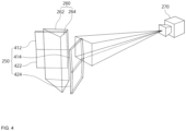
- FIG. 4 is a see-through perspective view of the third optical systems 250 and 260 of the intraoral scanner according to one embodiment of the present disclosure. Configurations of FIG. 4 that overlap with FIG. 2 will be briefly described based on the embodiment illustrated in FIG. 4 .
- the third optical systems 250 and 260 may include the fourth reflector 250 configured to reflect light reflected from the second optical system and the fifth reflector 260 configured to reflect light reflected by the fourth reflector 250 toward the image sensor part 270.
- the fourth reflector 250 may include two pairs of reflective surfaces, that is, four reflective surfaces 412, 414, 422, and 424, configured so that a dihedral angle between each pair of reflective surfaces is a minor angle.
- the first pair of reflective surfaces 412 and 414 may be configured so that a dihedral angle between the reflective surfaces is a minor angle.
- the second pair of reflective surfaces 422 and 424 may be configured so that a dihedral angle between the reflective surfaces is a minor angle.
- the fifth reflector 260 may include the two reflective surfaces 262 and 264 configured so that a dihedral angle between the reflective surfaces is a major angle.
- the two reflective surfaces 262 and 264 may be configured to be connected to each other through one side edge of each reflective surface.
- the positions and directions of the four reflective surfaces 412, 414, 422, and 424 of the fourth reflector 250 may be set so that two images of the subject each reflected by the four reflective surfaces 412, 414, 422, and 424 of the fourth reflector 250 and the two reflective surfaces 262 and 264 of the fifth reflector 260 and detected by the image sensor part do not overlap with each other.
- the positions and directions of the two reflective surfaces 262 and 264 of the fifth reflector 260 may be set so that two images of the subject each reflected by the two reflective surfaces 262 and 264 of the fifth reflector 260 and detected by the image sensor part 270 do not overlap with each other.
- the image sensor part 270 may obtain four stereo images from light reflected by the two reflective surfaces of the fifth reflector 260 of the third optical systems 250 and 260.
- a result of the image sensor part 270 obtaining the four stereo images from the fifth reflector 260 including the two reflective surfaces will be described in detail below with reference to FIG. 5 .
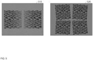
- FIG. 5 is a view illustrating examples of stereo images 510 and 520 obtained according to one embodiment of the present disclosure.
- the image sensor part (for example, 270 in FIG. 2 ) may be configured to detect light reflected from the third optical systems (for example, 250 and 260 in FIG. 2 ).
- the image sensor part may be configured to obtain two stereo images 510 from light reflected from the third optical systems.
- the image sensor part may simultaneously obtain two stereo images reflected by the two reflective surfaces (for example, 262 and 264 in FIG. 2 ) of the fifth reflector (for example, 260 in FIG. 2 ) of the third optical systems.
- the processor may extract depth data based on the two stereo images obtained in this way and may perform 3D modeling of an oral cavity structure, which is a subject, based on the depth data.
- the image sensor part may be configured to obtain four stereo images 520 from light reflected from the third optical systems. Specifically, the image sensor part may simultaneously obtain four stereo images reflected by the four reflective surfaces (for example, 412, 414, 422, and 424 in FIG. 4 ) of the fourth reflector (for example, 250 in FIG. 4 ) of the third optical systems and the two reflective surfaces (for example, 262 and 264 in FIG. 4 ) of the fifth reflector (for example, 260 in FIG. 4 ).
- the processor may extract depth data based on the four stereo images obtained in this way and may perform 3D modeling of an oral cavity structure, which is a subject, based on the depth data.
- FIG. 6 is a see-through lateral view of an intraoral scanner 600 according to another embodiment of the present disclosure. Configurations of FIG. 6 that overlap with FIG. 2 will be briefly described based on the embodiment illustrated in FIG. 6 .
- a light source part 620 may be configured to emit light toward an opening part 612.
- the light source part 620 may be disposed to be accommodated at the other end inside a case 610 that faces one end of the case 610 at which the opening part 612 or a second optical system 640 is formed.
- the light source part 620 may be disposed to be fixed to a lower portion of the other end inside the case 610.
- a first optical system 630 may be configured to, through a first reflector 632 and a second reflector 634, reflect light emitted from the light source part 620 toward the opening part 612 or the second optical system 640.
- the first reflector 632 disposed to be fixed to a lower portion inside the case 610 may be configured to reflect light emitted from the light source part 620 toward the second reflector 634.
- the second reflector 634 may be configured to reflect the light reflected by the first reflector 632 toward the opening part 612 or the second optical system 640.
- the second reflector 634 and the first reflector 632 may be disposed to be spaced apart from each other and fixed to a central portion inside the case 610.
- Light reflected from the second reflector 634 may be reflected toward a subject by the second optical system 640.
- the light may pass through an opening formed at one side of the opening part 612.
- Light reflected from the subject may be reflected again toward a third optical system 650 by the second optical system 640.
- Light reflected by the third optical system 650 may be reflected toward an image sensor part 670.
- the third optical system 650 may include the same configuration as the third optical systems 250 and 260 illustrated in FIG. 2 .
- the light source part 620 and the second optical system 640 may be disposed to be fixed to both ends of the space inside the case 610. Also, the first optical system 630 disposed at any position between the light source part 620 and the second optical system 640 may be disposed in an area that does not interfere with a path along which light that is reflected from the subject and reflected toward the third optical system 650 by the second optical system 640 passes, that is, a blind area.
- FIG. 7 is a see-through lateral view of an intraoral scanner 700 according to still another embodiment of the present disclosure. Configurations of FIG. 7 that overlap with FIG. 2 will be briefly described based on the embodiment illustrated in FIG. 7 .
- a light source part 720 may be configured to emit light toward an opening part 712 or a first optical system 730.
- the light source part 720 may be disposed to be accommodated at the other end inside a case 710 that faces one end of the case 710 at which the opening part 712 or a second optical system 740 is formed.
- the light source part 720 may be disposed to be fixed to an upper portion of the other end inside the case 710.
- the first optical system 730 may include a rhomboid prism including a first reflector 732 and a second reflector 734.
- first reflector 732 of the prism may be configured to reflect the light emitted from the light source part 720 toward the second reflector 734.
- the second reflector 734 may be configured to reflect the light reflected by the first reflector 732 toward the opening part 712 or the second optical system 740. That is, the light emitted from the light source part 720 may be reflected toward the second optical system 740 or the opening part 712 via the rhomboid prism of the first optical system 730.
- Light reflected from the second reflector 734 of the rhomboid prism may be reflected toward a subject by the second optical system 740.
- light may pass through an opening formed at one side of the opening part 712.
- Light reflected from the subject may be reflected again toward a third optical system 750 by the second optical system 740.
- Light reflected by the third optical system 750 may be reflected toward an image sensor part 770.
- the third optical system 750 may include the same configuration as the third optical systems 250 and 260 illustrated in FIG. 2 .
- the light source part 720 and the second optical system 740 may be disposed to be fixed to both ends of the space inside the case 710.
- the rhomboid prism which is the first optical system 730 disposed at any position between the light source part 720 and the second optical system 740, may be disposed in an area that does not interfere with a path along which light that is reflected from the subject and reflected toward the third optical system 750 by the second optical system 740 passes, that is, a blind area.
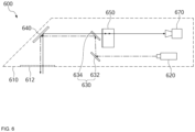
- FIG. 8 is a see-through lateral view of an intraoral scanner 800 according to yet another embodiment of the present disclosure. Configurations of FIG. 8 that overlap with FIG. 2 will be briefly described based on the embodiment illustrated in FIG. 8 .
- a light source part 820 may be configured to emit light toward an opening part 812 or a first optical system 830.
- the light source part 820 may include a first light source part 822 and a second light source part 824. Any one ray of light among rays of light emitted from the first light source part 822 and the second light source part 824 may correspond to patterned light or structured light, and another ray of light may correspond to normal light without a pattern.
- the first light source part 822 and the second light source part 824 may be configured to alternately emit light at predetermined time intervals. Also, the first light source part 822 and the second light source part 824 may be disposed together with an image sensor part 870 at the other end of a case 810 that faces one end of the case at which the opening part 812 is installed and may be disposed to be respectively fixed to an upper portion and a lower portion of the other end inside the case 810 while being symmetrical to each other about the image sensor part 870.
- the first optical system 830 may be configured to reflect light emitted from the light source part 820 toward the opening part 812 through a first reflector 832, a second reflector 834, and a third reflector 836. That is, the first reflector 832 and the third reflector 836 may be configured to reflect light emitted from the light source part 820 toward the second reflector 834.
- the first reflector 832 may be disposed to be fixed to an upper portion inside the case, and the third reflector 836 may be disposed to be fixed to a lower portion inside the case.
- the second reflector 834 may include two reflective surfaces each configured to reflect one of the light reflected by the first reflector 832 and the light reflected by the third reflector 836 toward the opening part 812 or a second optical system 840.
- a dihedral angle between the reflective surfaces of the second reflector 834 may be configured to form a major angle.
- the second reflector 834 may be disposed to be spaced apart from the first reflector 832 and the third reflector 836 and fixed to a central portion inside the case 810. That is, light emitted from the light source part 820 may be reflected toward the opening part 812 or the second optical system 840 via the first reflector 832, the third reflector 836, and the second reflector 834 of the first optical system 830.
- Light reflected from the second reflector 834 may be reflected toward a subject by the second optical system 840.
- light may pass through an opening formed at one side of the opening part 812.
- Light reflected from the subject may be reflected again toward a third optical system 850 by the second optical system 840.
- Light reflected by the third optical system 850 may be reflected toward the image sensor part 870.
- the third optical system 850 may include the same configuration as the third optical systems 250 and 260 illustrated in FIG. 2 .
- the light source part 820 and the second optical system 840 may be disposed to be fixed to both ends of the space inside the case 810.
- the first optical system 830 disposed at any position between the light source part 820 and the second optical system 840 may be disposed in an area that does not interfere with a path along which light that is reflected from the subject and reflected toward the third optical system 850 by the second optical system 840 passes, that is, a blind area. That is, the first optical system 830 may be disposed in an area that does not overlap with a portion of light reflected from the subject that is incident on the third optical system 850 (for example, an area adjacent to back surfaces in the opposite direction of the two reflective surfaces 262 and 264 of the fifth reflector 260).
- the components inside the case may be more densely arranged.
Landscapes
- Health & Medical Sciences (AREA)
- Life Sciences & Earth Sciences (AREA)
- Surgery (AREA)
- Animal Behavior & Ethology (AREA)
- General Health & Medical Sciences (AREA)
- Public Health (AREA)
- Veterinary Medicine (AREA)
- Physics & Mathematics (AREA)
- Biomedical Technology (AREA)
- Engineering & Computer Science (AREA)
- Biophysics (AREA)
- Optics & Photonics (AREA)
- Heart & Thoracic Surgery (AREA)
- Pathology (AREA)
- Medical Informatics (AREA)
- Molecular Biology (AREA)
- Radiology & Medical Imaging (AREA)
- Nuclear Medicine, Radiotherapy & Molecular Imaging (AREA)
- Dentistry (AREA)
- Oral & Maxillofacial Surgery (AREA)
- Epidemiology (AREA)
- Audiology, Speech & Language Pathology (AREA)
- Endoscopes (AREA)
- Dental Tools And Instruments Or Auxiliary Dental Instruments (AREA)
Applications Claiming Priority (2)
| Application Number | Priority Date | Filing Date | Title |
|---|---|---|---|
| KR1020210179478A KR102650667B1 (ko) | 2021-12-15 | 2021-12-15 | 구강 스캐너 |
| PCT/KR2022/020456 WO2023113499A1 (ko) | 2021-12-15 | 2022-12-15 | 구강 스캐너 |
Publications (2)
| Publication Number | Publication Date |
|---|---|
| EP4450022A1 true EP4450022A1 (de) | 2024-10-23 |
| EP4450022A4 EP4450022A4 (de) | 2025-10-01 |
Family
ID=86773124
Family Applications (1)
| Application Number | Title | Priority Date | Filing Date |
|---|---|---|---|
| EP22907966.0A Pending EP4450022A4 (de) | 2021-12-15 | 2022-12-15 | Intraoraler scanner |
Country Status (8)
| Country | Link |
|---|---|
| US (1) | US20250049312A1 (de) |
| EP (1) | EP4450022A4 (de) |
| JP (1) | JP2024545494A (de) |
| KR (4) | KR102650667B1 (de) |
| CN (1) | CN118414130A (de) |
| AU (1) | AU2022414974B2 (de) |
| CA (1) | CA3241682A1 (de) |
| WO (1) | WO2023113499A1 (de) |
Families Citing this family (5)
| Publication number | Priority date | Publication date | Assignee | Title |
|---|---|---|---|---|
| WO2023075545A1 (ko) * | 2021-10-29 | 2023-05-04 | 아크리얼 주식회사 | 구강 스캐너 |
| KR102847763B1 (ko) * | 2022-08-23 | 2025-08-20 | 주식회사 팀누비즈 | 단일 카메라로 스테레오 광학계를 구성한 3차원 이미지 구강 스캐너 |
| KR20250066328A (ko) * | 2023-11-06 | 2025-05-13 | 아크리얼 주식회사 | 구강 스캐너 |
| WO2025100831A1 (ko) * | 2023-11-06 | 2025-05-15 | 아크리얼 주식회사 | 구강 스캐너 |
| KR20250089272A (ko) * | 2023-12-11 | 2025-06-18 | 아크리얼 주식회사 | 구강 스캐너 |
Family Cites Families (20)
| Publication number | Priority date | Publication date | Assignee | Title |
|---|---|---|---|---|
| JPH08248328A (ja) * | 1995-03-14 | 1996-09-27 | Sanyo Electric Co Ltd | 立体内視鏡 |
| JP4265037B2 (ja) * | 1998-07-31 | 2009-05-20 | ソニー株式会社 | 三次元撮像装置とステレオカメラ記録再生システム |
| IL178393A0 (en) * | 2006-09-28 | 2007-02-11 | Boris Kayzerman | Improved x-ray apparatus |
| DE102007060263A1 (de) * | 2007-08-16 | 2009-02-26 | Steinbichler Optotechnik Gmbh | Vorrichtung zur Ermittlung der 3D-Koordinaten eines Objekts, insbesondere eines Zahns |
| WO2009139110A1 (ja) * | 2008-05-13 | 2009-11-19 | パナソニック株式会社 | 口腔内測定装置及び口腔内測定システム |
| US8456521B2 (en) * | 2009-12-14 | 2013-06-04 | Berliner Glas Kgaa Herbert Kubatz Gmbh & Co. | Triangulation camera device and triangulation imaging method |
| CN102008282B (zh) * | 2010-10-29 | 2012-08-08 | 深圳大学 | 数字印模口内扫描仪及口腔内表面形貌图像实时重建系统 |
| KR101483216B1 (ko) | 2012-08-31 | 2015-01-15 | 주식회사 오라픽스 | 구강 내 자동 스캐닝 시스템 및 스캐닝 방법 |
| KR101457108B1 (ko) * | 2012-09-25 | 2014-10-31 | 데오덴탈 주식회사 | 구강 스캐너 |
| DE102012220048B4 (de) * | 2012-11-02 | 2018-09-20 | Sirona Dental Systems Gmbh | Kalibrierungsvorrichtung und Verfahren zur Kalibrierung einer dentalen Kamera |
| CA2900268C (en) * | 2013-02-04 | 2021-04-06 | D4D Technologies, Llc | Intra-oral scanning device with illumination frames interspersed with image frames |
| KR101533341B1 (ko) * | 2014-03-04 | 2015-07-03 | 이태경 | 휴대형 스캐너 |
| EP3274675B1 (de) * | 2015-03-25 | 2021-07-21 | 3M Innovative Properties Company | Vorrichtung zur dentalen bildgebung und beleuchtung |
| KR20160133112A (ko) * | 2015-05-12 | 2016-11-22 | (주)바텍이우홀딩스 | 복수개의 광경로를 갖는 구강스캐너 |
| CN108478177B (zh) * | 2018-02-13 | 2020-11-27 | 苏州佳世达光电有限公司 | 口腔扫描仪 |
| KR101874547B1 (ko) | 2018-05-03 | 2018-07-04 | 주식회사 메디트 | 3차원 구강 스캐너 |
| JP2020032058A (ja) | 2018-08-31 | 2020-03-05 | 株式会社モリタ製作所 | キャップ、および撮像装置 |
| CN110500959A (zh) * | 2019-09-29 | 2019-11-26 | 中国科学院云南天文台 | 一种单摄像头口内三维扫描系统 |
| KR102414269B1 (ko) * | 2020-04-24 | 2022-06-29 | 주식회사 휴비츠 | 구강용 3d 컬러 스캐너 |
| US12310819B2 (en) * | 2021-07-23 | 2025-05-27 | Align Technology, Inc. | Intraoral scanner with illumination sequencing and controlled polarization |
-
2021
- 2021-12-15 KR KR1020210179478A patent/KR102650667B1/ko active Active
-
2022
- 2022-12-15 EP EP22907966.0A patent/EP4450022A4/de active Pending
- 2022-12-15 CA CA3241682A patent/CA3241682A1/en active Pending
- 2022-12-15 US US18/717,739 patent/US20250049312A1/en active Pending
- 2022-12-15 WO PCT/KR2022/020456 patent/WO2023113499A1/ko not_active Ceased
- 2022-12-15 AU AU2022414974A patent/AU2022414974B2/en active Active
- 2022-12-15 CN CN202280080759.8A patent/CN118414130A/zh active Pending
- 2022-12-15 JP JP2024533150A patent/JP2024545494A/ja active Pending
-
2024
- 2024-03-18 KR KR1020240037235A patent/KR102871916B1/ko active Active
- 2024-03-18 KR KR1020240037236A patent/KR102871917B1/ko active Active
- 2024-03-18 KR KR1020240037237A patent/KR20240038693A/ko active Pending
Also Published As
| Publication number | Publication date |
|---|---|
| CN118414130A (zh) | 2024-07-30 |
| EP4450022A4 (de) | 2025-10-01 |
| KR20240038692A (ko) | 2024-03-25 |
| WO2023113499A1 (ko) | 2023-06-22 |
| KR20240038691A (ko) | 2024-03-25 |
| KR20230090586A (ko) | 2023-06-22 |
| CA3241682A1 (en) | 2023-06-22 |
| JP2024545494A (ja) | 2024-12-09 |
| KR102650667B1 (ko) | 2024-03-22 |
| AU2022414974B2 (en) | 2025-06-26 |
| KR20240038693A (ko) | 2024-03-25 |
| KR102871916B1 (ko) | 2025-10-17 |
| AU2022414974A1 (en) | 2024-06-06 |
| US20250049312A1 (en) | 2025-02-13 |
| KR102650667B9 (ko) | 2026-02-03 |
| KR102871917B1 (ko) | 2025-10-17 |
Similar Documents
| Publication | Publication Date | Title |
|---|---|---|
| EP4450022A1 (de) | Intraoraler scanner | |
| KR102900973B1 (ko) | 구강 스캐너 | |
| US12472042B2 (en) | Intraoral scanner | |
| CN113116584B (zh) | 盖、摄像装置、数据生成系统以及数据生成方法 | |
| KR20170113412A (ko) | 치과용 구강스캐너 시스템 | |
| EP3202366B1 (de) | Methode, apparat und computer program zum abtasten eines objekts in drei dimensionen mit farbigen gestrichelten linienmustern | |
| EP4424272B1 (de) | Intraoraler scanner | |
| EP4424273A1 (de) | Intraoraler scanner | |
| EP4424274A1 (de) | Intraoraler scanner | |
| KR101358449B1 (ko) | 구강용 스캐닝 장치 및 그 스캐닝 방법 | |
| CN118159220A (zh) | 口内扫描仪 | |
| CN118201566A (zh) | 口内扫描仪 | |
| US20200302598A1 (en) | Medical image processing device and medical observation system | |
| KR20160111243A (ko) | 구강스캐너 | |
| JP2013094944A (ja) | 移動体操作装置 |
Legal Events
| Date | Code | Title | Description |
|---|---|---|---|
| STAA | Information on the status of an ep patent application or granted ep patent |
Free format text: STATUS: THE INTERNATIONAL PUBLICATION HAS BEEN MADE |
|
| PUAI | Public reference made under article 153(3) epc to a published international application that has entered the european phase |
Free format text: ORIGINAL CODE: 0009012 |
|
| STAA | Information on the status of an ep patent application or granted ep patent |
Free format text: STATUS: REQUEST FOR EXAMINATION WAS MADE |
|
| 17P | Request for examination filed |
Effective date: 20240604 |
|
| AK | Designated contracting states |
Kind code of ref document: A1 Designated state(s): AL AT BE BG CH CY CZ DE DK EE ES FI FR GB GR HR HU IE IS IT LI LT LU LV MC ME MK MT NL NO PL PT RO RS SE SI SK SM TR |
|
| DAV | Request for validation of the european patent (deleted) | ||
| DAX | Request for extension of the european patent (deleted) | ||
| A4 | Supplementary search report drawn up and despatched |
Effective date: 20250901 |
|
| RAP3 | Party data changed (applicant data changed or rights of an application transferred) |
Owner name: ARCREAL INC. |
|
| RIC1 | Information provided on ipc code assigned before grant |
Ipc: A61C 9/00 20060101AFI20250826BHEP Ipc: A61B 1/247 20060101ALI20250826BHEP Ipc: A61B 1/00 20060101ALI20250826BHEP |