EP4446293A1 - Transparentes keramikglas für ein kochfeld und kochfeld damit - Google Patents
Transparentes keramikglas für ein kochfeld und kochfeld damit Download PDFInfo
- Publication number
- EP4446293A1 EP4446293A1 EP23816220.0A EP23816220A EP4446293A1 EP 4446293 A1 EP4446293 A1 EP 4446293A1 EP 23816220 A EP23816220 A EP 23816220A EP 4446293 A1 EP4446293 A1 EP 4446293A1
- Authority
- EP
- European Patent Office
- Prior art keywords
- glass
- ceramic
- cooktop
- transparent glass
- printed layer
- Prior art date
- Legal status (The legal status is an assumption and is not a legal conclusion. Google has not performed a legal analysis and makes no representation as to the accuracy of the status listed.)
- Pending
Links
Images





Classifications
-
- H—ELECTRICITY
- H05—ELECTRIC TECHNIQUES NOT OTHERWISE PROVIDED FOR
- H05B—ELECTRIC HEATING; ELECTRIC LIGHT SOURCES NOT OTHERWISE PROVIDED FOR; CIRCUIT ARRANGEMENTS FOR ELECTRIC LIGHT SOURCES, IN GENERAL
- H05B6/00—Heating by electric, magnetic or electromagnetic fields
- H05B6/02—Induction heating
- H05B6/10—Induction heating apparatus, other than furnaces, for specific applications
- H05B6/12—Cooking devices
-
- B—PERFORMING OPERATIONS; TRANSPORTING
- B24—GRINDING; POLISHING
- B24B—MACHINES, DEVICES, OR PROCESSES FOR GRINDING OR POLISHING; DRESSING OR CONDITIONING OF ABRADING SURFACES; FEEDING OF GRINDING, POLISHING, OR LAPPING AGENTS
- B24B7/00—Machines or devices designed for grinding plane surfaces on work, including polishing plane glass surfaces; Accessories therefor
- B24B7/20—Machines or devices designed for grinding plane surfaces on work, including polishing plane glass surfaces; Accessories therefor characterised by a special design with respect to properties of the material of non-metallic articles to be ground
- B24B7/22—Machines or devices designed for grinding plane surfaces on work, including polishing plane glass surfaces; Accessories therefor characterised by a special design with respect to properties of the material of non-metallic articles to be ground for grinding inorganic material, e.g. stone, ceramics, porcelain
- B24B7/24—Machines or devices designed for grinding plane surfaces on work, including polishing plane glass surfaces; Accessories therefor characterised by a special design with respect to properties of the material of non-metallic articles to be ground for grinding inorganic material, e.g. stone, ceramics, porcelain for grinding or polishing glass
-
- C—CHEMISTRY; METALLURGY
- C03—GLASS; MINERAL OR SLAG WOOL
- C03C—CHEMICAL COMPOSITION OF GLASSES, GLAZES OR VITREOUS ENAMELS; SURFACE TREATMENT OF GLASS; SURFACE TREATMENT OF FIBRES OR FILAMENTS MADE FROM GLASS, MINERALS OR SLAGS; JOINING GLASS TO GLASS OR OTHER MATERIALS
- C03C10/00—Devitrified glass ceramics, i.e. glass ceramics having a crystalline phase dispersed in a glassy phase and constituting at least 50% by weight of the total composition
- C03C10/0018—Devitrified glass ceramics, i.e. glass ceramics having a crystalline phase dispersed in a glassy phase and constituting at least 50% by weight of the total composition containing SiO2, Al2O3 and monovalent metal oxide as main constituents
- C03C10/0027—Devitrified glass ceramics, i.e. glass ceramics having a crystalline phase dispersed in a glassy phase and constituting at least 50% by weight of the total composition containing SiO2, Al2O3 and monovalent metal oxide as main constituents containing SiO2, Al2O3, Li2O as main constituents
-
- C—CHEMISTRY; METALLURGY
- C03—GLASS; MINERAL OR SLAG WOOL
- C03C—CHEMICAL COMPOSITION OF GLASSES, GLAZES OR VITREOUS ENAMELS; SURFACE TREATMENT OF GLASS; SURFACE TREATMENT OF FIBRES OR FILAMENTS MADE FROM GLASS, MINERALS OR SLAGS; JOINING GLASS TO GLASS OR OTHER MATERIALS
- C03C15/00—Surface treatment of glass, not in the form of fibres or filaments, by etching
-
- C—CHEMISTRY; METALLURGY
- C03—GLASS; MINERAL OR SLAG WOOL
- C03C—CHEMICAL COMPOSITION OF GLASSES, GLAZES OR VITREOUS ENAMELS; SURFACE TREATMENT OF GLASS; SURFACE TREATMENT OF FIBRES OR FILAMENTS MADE FROM GLASS, MINERALS OR SLAGS; JOINING GLASS TO GLASS OR OTHER MATERIALS
- C03C17/00—Surface treatment of glass, not in the form of fibres or filaments, by coating
-
- C—CHEMISTRY; METALLURGY
- C03—GLASS; MINERAL OR SLAG WOOL
- C03C—CHEMICAL COMPOSITION OF GLASSES, GLAZES OR VITREOUS ENAMELS; SURFACE TREATMENT OF GLASS; SURFACE TREATMENT OF FIBRES OR FILAMENTS MADE FROM GLASS, MINERALS OR SLAGS; JOINING GLASS TO GLASS OR OTHER MATERIALS
- C03C17/00—Surface treatment of glass, not in the form of fibres or filaments, by coating
- C03C17/001—General methods for coating; Devices therefor
- C03C17/002—General methods for coating; Devices therefor for flat glass, e.g. float glass
-
- C—CHEMISTRY; METALLURGY
- C03—GLASS; MINERAL OR SLAG WOOL
- C03C—CHEMICAL COMPOSITION OF GLASSES, GLAZES OR VITREOUS ENAMELS; SURFACE TREATMENT OF GLASS; SURFACE TREATMENT OF FIBRES OR FILAMENTS MADE FROM GLASS, MINERALS OR SLAGS; JOINING GLASS TO GLASS OR OTHER MATERIALS
- C03C17/00—Surface treatment of glass, not in the form of fibres or filaments, by coating
- C03C17/34—Surface treatment of glass, not in the form of fibres or filaments, by coating with at least two coatings having different compositions
-
- C—CHEMISTRY; METALLURGY
- C03—GLASS; MINERAL OR SLAG WOOL
- C03C—CHEMICAL COMPOSITION OF GLASSES, GLAZES OR VITREOUS ENAMELS; SURFACE TREATMENT OF GLASS; SURFACE TREATMENT OF FIBRES OR FILAMENTS MADE FROM GLASS, MINERALS OR SLAGS; JOINING GLASS TO GLASS OR OTHER MATERIALS
- C03C17/00—Surface treatment of glass, not in the form of fibres or filaments, by coating
- C03C17/34—Surface treatment of glass, not in the form of fibres or filaments, by coating with at least two coatings having different compositions
- C03C17/36—Surface treatment of glass, not in the form of fibres or filaments, by coating with at least two coatings having different compositions at least one coating being a metal
-
- C—CHEMISTRY; METALLURGY
- C03—GLASS; MINERAL OR SLAG WOOL
- C03C—CHEMICAL COMPOSITION OF GLASSES, GLAZES OR VITREOUS ENAMELS; SURFACE TREATMENT OF GLASS; SURFACE TREATMENT OF FIBRES OR FILAMENTS MADE FROM GLASS, MINERALS OR SLAGS; JOINING GLASS TO GLASS OR OTHER MATERIALS
- C03C17/00—Surface treatment of glass, not in the form of fibres or filaments, by coating
- C03C17/34—Surface treatment of glass, not in the form of fibres or filaments, by coating with at least two coatings having different compositions
- C03C17/36—Surface treatment of glass, not in the form of fibres or filaments, by coating with at least two coatings having different compositions at least one coating being a metal
- C03C17/3602—Surface treatment of glass, not in the form of fibres or filaments, by coating with at least two coatings having different compositions at least one coating being a metal the metal being present as a layer
- C03C17/3657—Surface treatment of glass, not in the form of fibres or filaments, by coating with at least two coatings having different compositions at least one coating being a metal the metal being present as a layer the multilayer coating having optical properties
-
- F—MECHANICAL ENGINEERING; LIGHTING; HEATING; WEAPONS; BLASTING
- F24—HEATING; RANGES; VENTILATING
- F24C—DOMESTIC STOVES OR RANGES ; DETAILS OF DOMESTIC STOVES OR RANGES, OF GENERAL APPLICATION
- F24C15/00—Details
- F24C15/10—Tops, e.g. hot plates; Rings
-
- H—ELECTRICITY
- H05—ELECTRIC TECHNIQUES NOT OTHERWISE PROVIDED FOR
- H05B—ELECTRIC HEATING; ELECTRIC LIGHT SOURCES NOT OTHERWISE PROVIDED FOR; CIRCUIT ARRANGEMENTS FOR ELECTRIC LIGHT SOURCES, IN GENERAL
- H05B6/00—Heating by electric, magnetic or electromagnetic fields
- H05B6/02—Induction heating
- H05B6/10—Induction heating apparatus, other than furnaces, for specific applications
- H05B6/12—Cooking devices
- H05B6/1209—Cooking devices induction cooking plates or the like and devices to be used in combination with them
-
- C—CHEMISTRY; METALLURGY
- C03—GLASS; MINERAL OR SLAG WOOL
- C03C—CHEMICAL COMPOSITION OF GLASSES, GLAZES OR VITREOUS ENAMELS; SURFACE TREATMENT OF GLASS; SURFACE TREATMENT OF FIBRES OR FILAMENTS MADE FROM GLASS, MINERALS OR SLAGS; JOINING GLASS TO GLASS OR OTHER MATERIALS
- C03C2204/00—Glasses, glazes or enamels with special properties
- C03C2204/08—Glass having a rough surface
-
- C—CHEMISTRY; METALLURGY
- C03—GLASS; MINERAL OR SLAG WOOL
- C03C—CHEMICAL COMPOSITION OF GLASSES, GLAZES OR VITREOUS ENAMELS; SURFACE TREATMENT OF GLASS; SURFACE TREATMENT OF FIBRES OR FILAMENTS MADE FROM GLASS, MINERALS OR SLAGS; JOINING GLASS TO GLASS OR OTHER MATERIALS
- C03C2217/00—Coatings on glass
- C03C2217/70—Properties of coatings
- C03C2217/75—Hydrophilic and oleophilic coatings
-
- C—CHEMISTRY; METALLURGY
- C03—GLASS; MINERAL OR SLAG WOOL
- C03C—CHEMICAL COMPOSITION OF GLASSES, GLAZES OR VITREOUS ENAMELS; SURFACE TREATMENT OF GLASS; SURFACE TREATMENT OF FIBRES OR FILAMENTS MADE FROM GLASS, MINERALS OR SLAGS; JOINING GLASS TO GLASS OR OTHER MATERIALS
- C03C2218/00—Methods for coating glass
- C03C2218/30—Aspects of methods for coating glass not covered above
- C03C2218/365—Coating different sides of a glass substrate
Definitions
- the present disclosure relates to a transparent glass-ceramic for a cooktop and a cooktop including the same.
- Induction ranges induction heating apparatuses
- cooktops or hobs
- cooking apparatuses for heating food using induction ranges.
- a glass-ceramic with excellent heat resistance have been used on the top of cooktops.
- a glass-ceramic has excellent mechanical strength and thermal conductivity and are rarely fractured by thermal shock.
- a glass-ceramic is classified into white, black, and transparent glass-ceramic according to color. Among them, a transparent glass-ceramic has low aesthetic property due to high scratch visibility. In addition, A transparent glass-ceramic has low color heat resistance discolor at a high temperature.
- a transparent glass-ceramic for cooktop having low scratch visibility and excellent cleanability by controlling surface roughness, and a cooktop including the same.
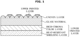
- a transparent glass-ceramic for a cooktop may include a glass material having an uneven layer formed on the surface, an upper printed layer formed on the uneven layer; and a lower printed layer formed under the glass material.
- a method of manufacturing a transparent glass-ceramic for a cooktop includes preparing a glass-ceramic precursor, forming crystals by heating the glass-ceramic precursor, cooling the glass-ceramic in which the crystals are formed, etching and blasting the cooled glass-ceramic, polishing the etched and blasted glass-ceramic, and printing on the polished glass-ceramic.
- a cooktop includes a cooktop main body, and a first glass provided on the cooktop main body, wherein the first glass comprises a glass-ceramic, and the glass-ceramic includes a glass material having an uneven layer formed on the surface, an upper printed layer formed on the uneven layer, and a lower printed layer formed under the glass material.
- a transparent glass-ceramic for cooktop having low scratch visibility and excellent cleanability and a cooktop including the same may be provided by optimizing surface roughness via etching, blasting, and polishing processes.
- the effects obtainable by the transparent glass-ceramic for cooktop and the cooktop including the same according to the present disclosure are not limited to the aforementioned effects, and any other effects not mentioned herein will be clearly understood from the following description by those skilled in the art to which the present disclosure pertains.
- a transparent glass-ceramic for a cooktop may include a glass material having an uneven layer formed on the surface, an upper printed layer formed on the uneven layer, and a lower printed layer formed under the glass material.
- the transparent glass-ceramic may further include an outermost coating layer provided on the upper printed layer.
- FIG. 1 is a schematic diagram of a transparent glass-ceramic for a cooktop according to an embodiment.
- a transparent glass-ceramic for a cooktop includes a glass material having an uneven layer formed on the surface, an upper printed layer, and a lower printed layer.
- the glass material may include, in percent by weight (wt%), 3 to 10% of Li 2 O, 15 to 25% of Al 2 O 3 , and the balance of SiO 2 and impurities.
- Li 2 O serves to increase hardness of a glass-ceramic.
- the glass-ceramic may not have a sufficient hardness.
- an excess of Li 2 O may increase manufacturing costs.
- Al 2 O 3 serves to improve corrosion resistance and durability of a glass-ceramic. Therefore, with a low content of Al 2 O 3 , corrosion resistance and durability of the glass-ceramic may deteriorate. However, an excess of Al 2 O 3 may increase manufacturing costs.
- SiO 2 serves as a nucleating agent in a glass-ceramic. Therefore, with a low content of SiO 2 , crystals are not sufficiently formed in the glass-ceramic and thus reflectance may deteriorate. However, an excess of SiO 2 may deteriorate hardness and durability of the glass-ceramic.
- the glass material may have a thickness of 3 to 5 mm.
- the embodiment is not limited thereto and the thickness of the glass material may vary according to the purpose and shape.
- the upper printed layer may include at least one of an UX printed layer and an UI printed layer.
- the upper printed layer may be formed to indicate the centers of induction elements on the top of the glass material.
- the upper printed layer may have a pattern in the form of a line or a cross to indicate the center of the induction element, but the embodiment is not limited thereto.
- the lower printed layer may include a high-chroma color layer and a heat-resistant shielding layer.
- the present disclosure relates to a transparent glass-ceramic capable of realizing various high-chroma colors unlike black glass-ceramic and white glass-ceramic. Therefore, clear high-chroma colors may be realized by disposing the high-chroma color layer under the transparent glass-ceramic.
- the heat-resistant shielding layer may serve to improve high-temperature heat resistance of the transparent glass-ceramic. Therefore, the transparent glass-ceramic including the heat-resistant shielding layer may have a high-chroma color maintained even after being exposed to a high temperature for a long time.
- the heat-resistant shielding layer may be an inorganic printed layer including at least one of C, Si, Ti, Cr, Cu and Al.
- An outermost coating layer formed on the upper printed layer may include at least one of antifouling coating, oleophobic coating, and anti-fingerprint coating.
- the transparent glass-ceramic for a cooktop may have a water contact angle of 90° or more. That is, cleanability may be improved by increasing the contact angle using the outermost coating layer.
- the transparent glass-ceramic for a cooktop may have a surface roughness Ra of 3 to 5 ⁇ m by etching, blasting and polishing processes which will be described below.
- the present disclosure may simultaneously control scratch visibility and cleanability, which are in a trade-off relationship, by optimizing the surface roughness.
- Aesthetic property of the transparent glass-ceramic for a cooktop may be improved by disposing the high-chroma color layer under the transparent glass-ceramic. More specifically, a transparent glass-ceramic having a black color layer may have a value L of 25 to 30 when measured using a color-difference meter, a transparent glass-ceramic having a dark grey color layer may have a value L of 30 to 35 when measured using a color-difference meter, a transparent glass-ceramic having silver and pink color layers may have a value L of 65 to 70 when measured using a color-difference meter, and a transparent glass-ceramic having a beige color layer may have a value L of 70 to 75 when measured using a color-difference meter.
- the transparent glass-ceramic for a cooktop may have a transmittance of 10 to 95%. Therefore, an LCD substrate may be used under the glass-ceramic for a cooktop using high transmittance, and various colors may be realized.
- the transmittance may be from 30 to 80%, and more preferably, the transmittance may be from 60 to 70%.
- the transparent glass-ceramic for a cooktop may have a 60° gloss of 2 to 10 GU. Therefore, the transparent glass-ceramic for a cooktop may have low scratch visibility due to low gloss.
- the method of manufacturing a transparent glass-ceramic for a cooktop may include: preparing a glass-ceramic precursor; forming crystals by heating the glass-ceramic precursor; cooling the glass-ceramic in which the crystals are formed; etching and blasting the cooled glass-ceramic; polishing the etched glass-ceramic; and printing on the polished glass-ceramic.
- FIG. 2 is a flowchart of a method of manufacturing a transparent glass-ceramic for a cooktop according to an embodiment.
- the method of manufacturing the transparent glass-ceramic for a cooktop may include a series of the glass-ceramic precursor-preparing process, crystal-forming process, cooling process, etching and blasting process, polishing process, and printing process.
- the method of manufacturing the transparent glass-ceramic for a cooktop may further include forming an outermost coating layer, if required, to further improve cleanability.
- a glass-ceramic prepared in the form of powder is melted at a temperature of 1400 to 1600°C and then cooled to room temperature at a rate of 40°C/min or less to prepare a glass-ceramic precursor.
- the crystal-forming process is performed to form crystals in the glass-ceramic.
- the crystal-forming process may include a first heat treatment performed at a temperature of 600 to 800°C for 10 to 20 minutes and a second heat treatment performed at a temperature of 800 to 1000°C for 20 to 30 minutes.
- Nuclei for crystallization are formed in the glass-ceramic by the first heat treatment, and crystallization proceeds by growing the nuclei by the second heat treatment.
- a too low temperature of the crystal-forming process or a too short time for the process may cause insufficient formation of crystals, resulting in deterioration of clarity of colors and reflectance.
- a too high temperature of the crystal-forming process or a too long time for the process may cause a decrease in productivity. Therefore, it is desirable to set appropriate levels of the temperature and time for the crystal-forming process temperature.
- the glass-ceramic that has undergone the crystal-forming process may be cooled to lower the temperature of the glass-ceramic to room temperature.
- the process of etching and blasting the surface of the cooled glass-ceramic may be performed.
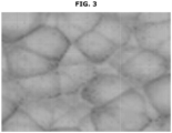
- FIG. 3 is an image of a surface of a transparent glass-ceramic after etching and blasting.
- the uneven layer may be formed by etching the surface of the glass-ceramic.
- the etched and blasted glass-ceramic may have a surface roughness Ra of 5 to 15 ⁇ m.
- the etching may be chemical etching.
- the etching may be performed by immersing the glass-ceramic in hydrofluoric acid. More specifically, the etching may be performed by spraying hydrofluoric acid onto the surface of the transparent glass-ceramic at room temperature and immersing the transparent glass-ceramic in hydrofluoric acid for 60 to 180 minutes.
- the blasting process may be performed by using diamond or both diamond and boron carbide.
- the etched and blasted glass-ceramic may be polished.
- the polishing process may be performed for 5 to 10 minutes.
- the glass-ceramic that has undergone the polishing process may have a surface roughness Ra of 3 to 5 ⁇ m.
- the upper printed layer may include at least one of the UX printed layer and the UI printed layer.
- the lower printed layer may include the high-chroma color layer and the heat-resistant shielding layer.
- At least one of antifouling coating, oleophobic coating, and anti-fingerprint coating may be formed.
- a cooktop may include a cooktop main body, and a first glass provided on the cooktop main body, wherein the first glass includes a glass-ceramic, and the glass-ceramic may include a glass material having an uneven layer formed on the surface, an upper printed layer formed on the uneven layer, and a lower printed layer formed under the glass material.
- the cooktop main body may include a heater
- the cooktop may include a second glass disposed on the same line as the first glass; a coupler allowing the first glass and the second glass to be detachably coupled to each other; a circuit board disposed under the second glass; and a coil mount disposed under the heater for seating the heater.
- An outermost coating layer may further be disposed on the upper printed layer, the lower printed layer may include a high-chroma color layer and a heat-resistant shielding layer, and the glass-ceramic may have a surface roughness Ra of 3 to 5 ⁇ m and a transmittance of 10 to 95%.
- the glass material is as described above and hereinafter, the cooktop will be described in more detail.
- the cooktop may include a cooktop main body, and a first glass disposed on the cooktop main body, wherein the first glass may include a glass-ceramic.
- the cooktop main body may include a heater
- the cooktop may include a second glass disposed on the same line as the first glass, a coupler allowing the first glass and the second glass to be detachably coupled to each other, a circuit board disposed under the second glass, and a coil mount disposed under the heater for seating the heater.
- FIG. 4 is a diagram of a cooktop according to an embodiment.
- FIG. 5 is an exploded perspective view of a cooktop according to an embodiment of the present disclosure.
- a cooktop 1 may include a cooktop main body 10 and a first glass 110 disposed on the cooktop main body 10.
- the cooktop 1 may include a heater (hereinafter, referred to as induction heating coil 11), a second glass 120, a coupler 200, a circuit board 12, and a coil mount 15.
- a heater hereinafter, referred to as induction heating coil 11
- second glass 120 may be included in the cooktop 1
- coupler 200 may be included in the cooktop 1
- circuit board 12 may be included in the cooktop 1
- coil mount 15 may include a heater (hereinafter, referred to as induction heating coil 11), a second glass 120, a coupler 200, a circuit board 12, and a coil mount 15.
- the main body 10 may define an exterior appearance of the cooking apparatus 1.
- the induction heating coil 11 may be accommodated in the main body 10 and generate a magnetic field for induction heating of a cooking vessel 2.
- the induction heating coil 11 may be electrically connected to a main substrate (not shown) provided inside the main body 10 via an electric wire 11a.
- the glass 100 may include a first glass 110 constituting a first region 101 and a second glass 120 constituting a second region 102.
- the circuit board 12 may be disposed under the second glass 120.
- the circuit board 12 may include a display device 13 and a touch device 14.
- the display device 13 may be disposed under a display 102a formed at the second region 102.
- the display device 13 may display whether the cooking vessel 2 is heated by the induction heating coil 11. Thus, a user may determine whether the cooking vessel 2 is heated via the display 102a.
- the touch device 14 may be disposed under an input device 102b formed at the second region 102.
- the touch device 14 may receive a tough signal from the input device 102b.
- the touch device 14 may receive an input by a capacitive touch method.
- the embodiment is not limited thereto, and the touch device 14 may receive an input by a resistive touch method.
- the user may adjust a current flowing in the induction heating coil and determine the degree of heating the cooking vessel 2 via the input device 102b.
- the induction heating coil 11 may be seated on the coil mount 15.
- a coil mounting hole 15a may be provided in the coil mount 15 to mount the induction heating coil 11.
- the coil mounting hole 15a may be provided in plural.
- the main body 10 may further include a first frame 16 provided to support the glass 100.
- the first frame 16 may be provided to support the glass 100 disposed on the top thereof.
- the first frame 16 may be formed by extending upward from four ends of the coil mount 15. The first frame 16 is provided such that the glass 100 is seated in the main body 10 and supported thereby.
- the first glass 110 may include the upper printed layer (heating area guides 101a, 101b, and 101c) and support the cooking vessel 2.
- the cooking vessel 2 may be located in the first region 101.
- the second glass 120 may include a second region 102, and the second region 102 may include the display 102a and the input device 102b.
- the display 102a is located in the second region 102 to display various information about the cooking apparatus 1, and the input device 102b may be located in the second region 102 to receive a control command from the user.
- the first glass 110 and the second glass 120 are physically separated from each other and may be detachably coupled to each other by the coupler 200.
- the first glass 110 and the second glass 120 may be detachably coupled to each other by the coupler 200.
- the first glass 110 constitutes the first region 101 and the cooking vessel 2 may be located on the first region 101.
- the cooking vessel 2 located on the first glass 110 may be induction-heated by a magnetic field generated by the induction heating coil 15.
- the second glass 120 constitutes the second region 102 separated from the first region 101, and cooking information including temperature of the cooking vessel 2, cooking time, and/or date/time may be displayed in the second region 102 via the display 102a.
- the input device 102b configured to receive a control command from the user may be provided in the second region 102 to turn on/off the cooking apparatus 1 or control the temperature of the cooking vessel 2.
- the input device 102b may receive an input by a touch of the user.
- the second glass 120 may be a tempered glass.
- the first glass 110 may be formed of a material different from that used to form the second glass 120.
- the first glass 110 may be formed of a glass-ceramic having excellent heat resistance, and the second glass 120 may have a property of transferring a touch signal to the circuit board 12 provided at a lower portion via a touch.
- the first glass 110 and the second glass 120 may be detachably coupled to each other by the coupler 200.
- the second glass 120 may be detachably coupled to the first glass 110 by the coupler 200.
- the second glass 120 may be coupled to the front of the first glass 110.
- the second glass 120 may cover one side of the first glass 110 when coupled to the first glass 110.
- maintenance and repair of the circuit board 12 located in the second region 102 may be easily performed because the second glass 120 corresponding to the second region 102 is easily separated and replaced.
- Table 1 below shows that vertical forces at the time of scratching in comparative examples and an example.
- Comparative Example 1 shows a transparent glass-ceramic without a coating layer
- Comparative Example 2 shows a transparent glass-ceramic with an ALSiN coating layer
- Comparative Example 3 shows a transparent glass-ceramic with a DLC coating layer
- Example 1 shows a transparent glass-ceramic with an uneven layer according to an embodiment.
- the scratch resistance test was a variable load scratch test.
- FIG. 6 is a schematic diagram of a scratch resistance test.
- a variable load scratch test was performed according to the ASTM c-1624-05 Standard Test Method using a Fischerscope ® -HM2000 device.
- a vertical force applied to the specimens was increased at a steady rate from 0.5 N to 20 N, and scratch behavior was observed using an optical or electron microscope while moving each specimen at a rate of 240 mm/s.
- Table 2 below shows of surface roughness Ra and degrees scratch visibility according to the comparative examples and examples.
- Comparative Example 4 shows a transparent glass-ceramic not having a coating and including a black lower printed layer
- Comparative Example 5 shows a transparent glass-ceramic not having a coating and including a pink lower printed layer.
- Example 2 shows a transparent glass-ceramic having an uneven layer and including a black lower printed layer
- Example 3 shows a transparent glass-ceramic having an uneven layer and including a pink lower printed layer.
- the surface roughness Ra was obtained by measuring a vertical movement of a stylus tip vertically moving on a surface of each specimen at room temperature (25°C) using a surface roughness measuring device.
- the scratch visibility test was performed by reciprocating a sandpaper at 100 rpm using an abrasion resistance tester and observing scratches formed thereon using an optical microscope.
- a scratch width greater than 5 mm was evaluated as Lv. 1
- a scratch width greater than 2.5 mm and equal to or less than 5 mm was evaluated as Lv.2
- a scratch width equal to or greater than 1.0 mm and equal to or less than 2.5 mm was evaluated as Lv.3
- a scratch width greater than 0.1 mm and less than 1.0 mm was evaluated as Lv.4
- a scratch width equal to or less than 0.1 mm was evaluated as Lv.5.
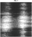
- FIG. 7 is an image showing a scratch test result of Comparative Example 4
- FIG. 8 is an image showing a scratch test result of Example 2. Referring to FIGS. 7 and 8 , it may be confirmed that the transparent glass-ceramic according to the embodiment has significantly low scratch visibility by forming the uneven layer.
- Table 3 below shows gloss and fingerprint visibility of comparative examples and examples.
- Gloss was measured according to the ASTM D523. D2457 standard at room temperature at a measurement angle of 60° using a BYK #4446 glossmeter.
- the degree of fingerprint visibility was measured by pressing each of the specimens of the comparative examples and examples for 10 seconds with a finger and measuring a color difference ⁇ E between a region pressed by the finger and another region not pressed thereby.
- the color difference ⁇ E was obtained by measuring L*a*b* color-difference using Spectrophotometer CM-2600d.
- Example 2 4.2 0.1
- Example 3 2.5 0.1
- Comparative Examples 4 and 5 show very high glosses and relatively high color difference values between the region pressed by the finger and the region not pressed by the finger. That is, Comparative Examples 4 and 5 had high fingerprint visibility.
- Examples 2 and 3 including the uneven layer had low glosses and very low color difference values between the region pressed by the finger and the region not pressed by the finger. That is, Examples 2 and 3 exhibited low fingerprint visibility.
- FIG. 9 is an image showing a fingerprint visibility test result of Comparative Example 4.
- FIG. 10 is an image showing a fingerprint visibility test result of Example 2.
- the transparent glass-ceramic according to an embodiment has a significantly low fingerprint visibility by forming the uneven layer.
- Cleanability evaluation was obtained by applying a cooking oil to a part of the surface of each specimen of Example 2 and Comparative Example 6, heating the oil at 220°C for 30 minutes, and measuring a color difference value ⁇ E before and after the heating.
- Comparative Example 6 shows a transparent glass-ceramic having a surface roughness Ra of 7 ⁇ m because the polishing process was not performed.
- Example 2 shows a color difference value ⁇ E of 0.6
- Comparative Example 6 shows a color difference value ⁇ E of 1.5. That is, it was confirmed that the transparent glass-ceramic according to an embodiment also had excellent cleanability by optimizing the surface roughness by the polishing process.
- Heat resistance was evaluated by heating the specimens of Example 3 and Comparative Example 5 (a width of 100 mm X a length of 100 mm) at 350°C for 100 hours, removing a contaminant using a scrapper or water, and measuring color difference values ⁇ E before and after contamination.
- Example 3 including the heat-resistant shielding layer exhibited a color difference value ⁇ E of 0.4
- Comparative Example 5 not including the heat-resistant shielding layer exhibited a color difference value ⁇ E of 1.35. That is, it was confirmed that the transparent glass-ceramic according to an embodiment has excellent heat resistance because discoloration did not occur even after being exposed to high temperature for a long time due to the heat-resistant shielding layer.
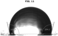
- a contact angle test was performed by dropping 1.0 ⁇ l of water droplets onto the specimen and measuring a contact angle at room temperature (25°C) using a contact angle measuring device of KRUSS.
- FIG. 11 is an image showing contact angle of a transparent glass-ceramic for a cooktop according to an embodiment.
- the transparent glass-ceramic for a cooktop according to an embodiment satisfied a water contact angle of 90° or more by forming the outermost coating layer. That is, cleanability of the transparent glass-ceramic for a cooktop according to an embodiment may further be improved by increasing the contact angle.
Landscapes
- Chemical & Material Sciences (AREA)
- Engineering & Computer Science (AREA)
- Materials Engineering (AREA)
- Organic Chemistry (AREA)
- Life Sciences & Earth Sciences (AREA)
- Chemical Kinetics & Catalysis (AREA)
- General Chemical & Material Sciences (AREA)
- Geochemistry & Mineralogy (AREA)
- Physics & Mathematics (AREA)
- Electromagnetism (AREA)
- Ceramic Engineering (AREA)
- Mechanical Engineering (AREA)
- Crystallography & Structural Chemistry (AREA)
- Dispersion Chemistry (AREA)
- Combustion & Propulsion (AREA)
- General Engineering & Computer Science (AREA)
- Inorganic Chemistry (AREA)
- Surface Treatment Of Glass (AREA)
Applications Claiming Priority (3)
| Application Number | Priority Date | Filing Date | Title |
|---|---|---|---|
| KR20220067819 | 2022-06-02 | ||
| KR1020220102339A KR20230167685A (ko) | 2022-06-02 | 2022-08-16 | 쿡탑용 투명 세라믹 글라스 및 이를 포함하는 쿡탑 |
| PCT/KR2023/005316 WO2023234555A1 (ko) | 2022-06-02 | 2023-04-19 | 쿡탑용 투명 세라믹 글라스 및 이를 포함하는 쿡탑 |
Publications (2)
| Publication Number | Publication Date |
|---|---|
| EP4446293A1 true EP4446293A1 (de) | 2024-10-16 |
| EP4446293A4 EP4446293A4 (de) | 2025-06-04 |
Family
ID=89025220
Family Applications (1)
| Application Number | Title | Priority Date | Filing Date |
|---|---|---|---|
| EP23816220.0A Pending EP4446293A4 (de) | 2022-06-02 | 2023-04-19 | Transparentes keramikglas für ein kochfeld und kochfeld damit |
Country Status (3)
| Country | Link |
|---|---|
| US (1) | US20230391662A1 (de) |
| EP (1) | EP4446293A4 (de) |
| WO (1) | WO2023234555A1 (de) |
Family Cites Families (15)
| Publication number | Priority date | Publication date | Assignee | Title |
|---|---|---|---|---|
| EP0619768B1 (de) * | 1992-10-02 | 1997-07-16 | Electrolux AG | Verfahren zum oberflächenbehandeln und zum rezyklieren von platten, nach einem dieser verfahren behandelte platte und oberflächen-behandlungsanlage |
| EP1325666A4 (de) * | 2000-08-18 | 2007-03-21 | Luxine Inc | Induktionserwärmungs- und steuersystem und verfahren mit hoher zuverlässigkeit und fortgeschrittenen leistungsmerkmalen |
| US6660980B2 (en) * | 2001-06-12 | 2003-12-09 | Nippon Electric Glass Co., Ltd. | Top plate for cooking device having electromagnetic-induction heating unit |
| JP3900939B2 (ja) * | 2002-01-22 | 2007-04-04 | 鳴海製陶株式会社 | 調理器用トッププレート |
| JP2007101134A (ja) * | 2005-10-07 | 2007-04-19 | Nippon Electric Glass Co Ltd | 調理器用トッププレート |
| FR2894328B1 (fr) * | 2005-12-05 | 2017-10-06 | Eurokera | Plaque vitroceramique transparente ou translucide et son procede de fabrication |
| DE102010045149A1 (de) * | 2010-09-11 | 2012-03-15 | Bayer Material Science Ag | Beschichtung auf Polyurethanbasis für Anzeigebereiche |
| JP2013087986A (ja) * | 2011-10-14 | 2013-05-13 | Nippon Electric Glass Co Ltd | 調理器用トッププレート用ガラス板及びその製造方法 |
| DE102012104168A1 (de) * | 2012-05-13 | 2013-11-14 | Schott Ag | Gehärtete Keatit-Glaskeramik |
| FR2992313B1 (fr) * | 2012-06-21 | 2014-11-07 | Eurokera | Article vitroceramique et procede de fabrication |
| DE102015104412A1 (de) * | 2015-03-24 | 2016-09-29 | Schott Ag | Verfahren zur Geometrieänderung von Glaskeramiken und verfahrensgemäß hergestellter beschichteter Glaskeramikartikel |
| FR3078066B1 (fr) * | 2018-02-19 | 2023-03-24 | Eurokera | Article vitrocéramique anti-traces de doigts |
| FR3078067B1 (fr) * | 2018-02-19 | 2023-03-24 | Eurokera | Article vitrocéramique anti-traces de doigts |
| US20230096157A1 (en) * | 2020-02-28 | 2023-03-30 | Panasonic Intellectual Property Management Co., Ltd. | Cooking device top plate |
| JP2021139614A (ja) * | 2020-02-28 | 2021-09-16 | パナソニックIpマネジメント株式会社 | 加熱調理器用トッププレート |
-
2023
- 2023-04-19 EP EP23816220.0A patent/EP4446293A4/de active Pending
- 2023-04-19 WO PCT/KR2023/005316 patent/WO2023234555A1/ko not_active Ceased
- 2023-06-27 US US18/214,877 patent/US20230391662A1/en active Pending
Also Published As
| Publication number | Publication date |
|---|---|
| WO2023234555A1 (ko) | 2023-12-07 |
| US20230391662A1 (en) | 2023-12-07 |
| EP4446293A4 (de) | 2025-06-04 |
Similar Documents
| Publication | Publication Date | Title |
|---|---|---|
| KR102550616B1 (ko) | 세라믹 글라스 및 이를 적용한 쿡탑 | |
| US6492622B2 (en) | Cooking arrangement for cooking food such as a stove, a cooktop, and other cooking appliances, with an easy-to-clean surface | |
| EP2233840B1 (de) | Oberplatte für kochgeräte | |
| EP1453770B1 (de) | Glaskeramikplatten, diese enthaltende heizplatten und herstellungsverfahren dafür | |
| JP7483616B2 (ja) | ガラスセラミック物品 | |
| KR20230113839A (ko) | 강화 유리 | |
| KR20230167685A (ko) | 쿡탑용 투명 세라믹 글라스 및 이를 포함하는 쿡탑 | |
| CN114620944A (zh) | 颜色中性的防磨损层、具有防磨损层的基底及其制造方法 | |
| JP2021513946A (ja) | ガラスセラミック物品 | |
| KR102698279B1 (ko) | 반투명 또는 투명 마모 방지 코팅, 이러한 마모 방지 코팅을 갖는 기재 및 그의 제조 방법 | |
| US20100264130A1 (en) | Top plate for cooking appliance and process for producing the same | |
| EP4446293A1 (de) | Transparentes keramikglas für ein kochfeld und kochfeld damit | |
| JP7579801B2 (ja) | ガラスセラミック物品 | |
| CN118647586A (zh) | 用于炉灶面的透明陶瓷玻璃和包含透明陶瓷玻璃的炉灶面 | |
| EP4458782A1 (de) | Oberplatte für kochgerät, verfahren zur verarbeitung eines glaskeramiksubstrats und vorrichtung damit | |
| JP2004211910A (ja) | 調理器用トッププレート | |
| KR20230111569A (ko) | 세라믹 글라스 및 이를 적용한 쿡탑 | |
| CN114040896B (zh) | 盖板、尤其用于加热食物的板,以及用于加热食物的设备 | |
| EP4434947A1 (de) | Keramikglas und kochfeld damit | |
| CN113825734B (zh) | 玻璃陶瓷制品 | |
| US20240182355A1 (en) | Glass-ceramic and cooktop using same | |
| US20230100027A1 (en) | Crystallizable lithium aluminum silicate glass and glass ceramic produced therefrom | |
| Willhauk et al. | Glass ceramics for household appliances |
Legal Events
| Date | Code | Title | Description |
|---|---|---|---|
| STAA | Information on the status of an ep patent application or granted ep patent |
Free format text: STATUS: THE INTERNATIONAL PUBLICATION HAS BEEN MADE |
|
| PUAI | Public reference made under article 153(3) epc to a published international application that has entered the european phase |
Free format text: ORIGINAL CODE: 0009012 |
|
| STAA | Information on the status of an ep patent application or granted ep patent |
Free format text: STATUS: REQUEST FOR EXAMINATION WAS MADE |
|
| 17P | Request for examination filed |
Effective date: 20240708 |
|
| AK | Designated contracting states |
Kind code of ref document: A1 Designated state(s): AL AT BE BG CH CY CZ DE DK EE ES FI FR GB GR HR HU IE IS IT LI LT LU LV MC ME MK MT NL NO PL PT RO RS SE SI SK SM TR |
|
| A4 | Supplementary search report drawn up and despatched |
Effective date: 20250508 |
|
| RIC1 | Information provided on ipc code assigned before grant |
Ipc: F24C 15/10 20060101ALI20250430BHEP Ipc: B24B 7/24 20060101ALI20250430BHEP Ipc: C03C 15/00 20060101ALI20250430BHEP Ipc: C03C 17/00 20060101ALI20250430BHEP Ipc: C03C 17/34 20060101ALI20250430BHEP Ipc: C03C 17/36 20060101AFI20250430BHEP |
|
| DAV | Request for validation of the european patent (deleted) | ||
| DAX | Request for extension of the european patent (deleted) |