EP4446134A1 - Tire - Google Patents
Tire Download PDFInfo
- Publication number
- EP4446134A1 EP4446134A1 EP22903760.1A EP22903760A EP4446134A1 EP 4446134 A1 EP4446134 A1 EP 4446134A1 EP 22903760 A EP22903760 A EP 22903760A EP 4446134 A1 EP4446134 A1 EP 4446134A1
- Authority
- EP
- European Patent Office
- Prior art keywords
- tire
- communication device
- label
- area
- label area
- Prior art date
- Legal status (The legal status is an assumption and is not a legal conclusion. Google has not performed a legal analysis and makes no representation as to the accuracy of the status listed.)
- Granted
Links
Images







Classifications
-
- B—PERFORMING OPERATIONS; TRANSPORTING
- B60—VEHICLES IN GENERAL
- B60C—VEHICLE TYRES; TYRE INFLATION; TYRE CHANGING; CONNECTING VALVES TO INFLATABLE ELASTIC BODIES IN GENERAL; DEVICES OR ARRANGEMENTS RELATED TO TYRES
- B60C19/00—Tyre parts or constructions not otherwise provided for
-
- B—PERFORMING OPERATIONS; TRANSPORTING
- B60—VEHICLES IN GENERAL
- B60C—VEHICLE TYRES; TYRE INFLATION; TYRE CHANGING; CONNECTING VALVES TO INFLATABLE ELASTIC BODIES IN GENERAL; DEVICES OR ARRANGEMENTS RELATED TO TYRES
- B60C13/00—Tyre sidewalls; Protecting, decorating, marking, or the like, thereof
- B60C13/001—Decorating, marking or the like
-
- B—PERFORMING OPERATIONS; TRANSPORTING
- B60—VEHICLES IN GENERAL
- B60C—VEHICLE TYRES; TYRE INFLATION; TYRE CHANGING; CONNECTING VALVES TO INFLATABLE ELASTIC BODIES IN GENERAL; DEVICES OR ARRANGEMENTS RELATED TO TYRES
- B60C11/00—Tyre tread bands; Tread patterns; Anti-skid inserts
-
- B—PERFORMING OPERATIONS; TRANSPORTING
- B60—VEHICLES IN GENERAL
- B60C—VEHICLE TYRES; TYRE INFLATION; TYRE CHANGING; CONNECTING VALVES TO INFLATABLE ELASTIC BODIES IN GENERAL; DEVICES OR ARRANGEMENTS RELATED TO TYRES
- B60C5/00—Inflatable pneumatic tyres or inner tubes
- B60C5/12—Inflatable pneumatic tyres or inner tubes without separate inflatable inserts, e.g. tubeless tyres with transverse section open to the rim
- B60C5/14—Inflatable pneumatic tyres or inner tubes without separate inflatable inserts, e.g. tubeless tyres with transverse section open to the rim with impervious liner or coating on the inner wall of the tyre
Definitions
- the present disclosure relates to a tire.
- Patent Literature (PTL) 1 discloses this type of tire.
- a tire as a first aspect of the present disclosure, includes a tire body and a communication device embedded within the tire body or mounted on an inner surface of the tire body.
- the tire includes a label area that is located on an outer surface of the tire body and indicates the position of the communication device.
- the label area includes a light emission area.
- a tire width direction refers to a direction parallel to the central axis of the tire.
- a tire radial direction refers to a radial direction that is orthogonal to the central axis of the tire and centered on the central axis.
- a tire circumferential direction refers to a direction in which the tire rotates about the central axis of the tire.
- a “tread outer surface” means an outer circumferential surface throughout the entire circumference of the tire that is in contact with a road surface when the tire mounted on a rim and filled with a specified internal pressure is rotated under a maximum load (hereinafter also referred to as “maximum load condition").
- “tread ends” mean outer ends of the tread outer surface in the tire width direction.
- the "rim” means a standard rim (Measuring Rim in ETRTO's STANDARDS MANUAL and Design Rim in TRA's YEAR BOOK) of an applicable size conformable to industrial standards valid for regions in which tires are produced and used, as described in or to be described in JATMA YEAR BOOK of the Japan Automobile Tyre Manufacturers Association, Inc. (JATMA) in Japan , STANDARDS MANUAL of the European Tyre and Rim Technical Organisation (ETRTO) in Europe , YEAR BOOK of the Tire and Rim Association, Inc.
- TRA in the United States , or the like, but in the case of a size that is not listed in such industrial standards, a rim with a width corresponding to a bead width of the tire.
- the "rim” may be of a size that may be included in the above industrial standards in the future, as well as a current size. Examples of the "size that is included in the future” may be sizes listed as " FUTURE DEVELOPMENTS” in the 2013 edition of STANDARDS MANUAL of the ETRTO .
- the "specified internal pressure” means an air pressure (maximum air pressure) corresponding to a maximum load capacity of a single wheel in an applicable size and ply rating as described in the above industrial standards such as JATMA YEAR BOOK, but in the case of a size that is not listed in the above industry standards, an air pressure (maximum air pressure) corresponding to a maximum load capacity specified for each vehicle on which the tire is mounted.
- the "maximum load” means a load corresponding to the maximum load capacity of the tire of an applicable size listed in the above industrial standards, but in the case of a size that is not listed in the above industrial standards, a load corresponding to the maximum load capacity specified for each vehicle on which the tire is mounted.
- a pneumatic tire 1 (hereinafter simply referred to as "tire 1") as an embodiment of the tire according to the present disclosure will be exemplarily described below with reference to the drawings.
- the tire 1 described below is assumed to mean a tire 1 that is mounted on a rim, filled with a specified internal pressure, and in a maximum load condition.
- the type of tire 1 is not particularly limited, and may be, for example, a tire for trucks or buses, or a tire for passenger cars.
- FIG. 1 is a cross-sectional view of the tire 1 in a tire width direction. As illustrated in FIG. 1 , the tire 1 includes a tire body 10 and a communication device 40.
- the tire body 10 includes a tread portion 10a, a first side portion 10b1, and a second side portion 10b2.
- the first side portion 10b1 extends from one end of the tread portion 10a in a tire width direction A toward an inner side B2 in a tire radial direction B.
- the second side portion 10b2 extends from the other end of the tread portion 10a in the tire width direction A toward the inner side B2 in the tire radial direction B.
- the first side portion 10b1 and the second side portion 10b2 are simply described as "side portions 10b" when not specifically distinguished.
- the side portions 10b each have a sidewall portion 11 and a bead portion 12.
- the sidewall portion 11 is connected to the end of the tread portion 10a in the tire width direction A and extends toward the inner side B2 in the tire radial direction B.
- the bead portion 12 is connected to an end of the sidewall portion 11 on the inner side B2 in the tire radial direction B.
- the tire body 10 of this embodiment includes bead cores 2, bead fillers 3, a carcass 4, belts 5, tread rubber 7, side rubber 8, and an inner liner 9.
- the tire body 10 may include other components, not limited to the above components.
- Each bead core 2 and the bead fillers 3 are embedded in the bead portions 12 of the side portions 10b.
- Each bead core 2 includes a bead cord that is surrounded by a rubber coating.
- the bead cord is formed of a steel cord.
- Each bead filler 3 is made of rubber and is located on an outer side B 1 in the tire radial direction B with respect to the bead core 2.
- the carcass 4 extends toroidally between the pair of bead portions 12, which is constituted of the bead portion 12 of the first side portion 10b1 and the bead portion 12 of the second side portion 10b2, more specifically between the pair of bead cores 2.
- the carcass 4 of this embodiment includes a carcass ply 4a.
- the carcass ply 4a is folded from the inside to the outside in the tire width direction A around the respective bead cores 2.
- the carcass ply 4a may have a plurality of ply cords arranged parallel to each other and coating rubber that coats the plurality of ply cords.
- the carcass 4 of this embodiment includes only one carcass ply 4a, but may include two or more carcass plies 4a.
- the plurality of ply cords of the carcass ply 4a may be arranged at an angle of, for example, 75° to 90° with respect to a tire circumferential direction C.
- the ply cords of the carcass ply 4a can be, for example, metal cords such as steel cords.
- the carcass ply 4a of this embodiment has a body part 4a1 located between the pair of bead cores 2, and folded parts 4a2 that are connected to the body part 4a1 and folded from the inside to the outside in the tire width direction A around the respective bead cores 2.
- the above-described bead fillers 3 are each located between the body part 4a1 and each folded part 4a2 of the carcass ply 4a.
- the belts 5 are embedded in the tread portion 10a.
- the tire body 10 of this embodiment has four of the belts 5 on the outer side B 1 of a crown part of the carcass 4 in the tire radial direction B.
- the four belts 5 of this embodiment include a first belt 5a, a second belt 5b, a third belt 5c, and a fourth belt 5d.
- the first belt 5a, the second belt 5b, the third belt 5c, and the fourth belt 5d are simply referred to as "belts 5" when not specifically distinguished.
- the first belt 5a is located at the most inner side B2 in the tire radial direction B, among the first belt 5a, the second belt 5b, the third belt 5c, and the fourth belt 5d.
- the fourth belt 5d is located at the most outer side B 1 in the tire radial direction B, among the first belt 5a, the second belt 5b, the third belt 5c, and the fourth belt 5d.
- the second belt 5b and the third belt 5c are located between the first belt 5a and the fourth belt 5d in the tire radial direction B. More specifically, the third belt 5c is located on the outer side B1 of the second belt 5b in the tire radial direction B.
- the first belt 5a, the second belt 5b, the third belt 5c, and the fourth belt 5d constitute four belt layers.
- the first belt 5a forms a first belt layer 20a located at the most inner side B2 in the tire radial direction B.
- the fourth belt 5d forms a fourth belt layer 20d located at the most outer side B1 in the tire radial direction B.
- the second belt 5b forms a second belt layer 20b.
- the third belt 5c forms a third belt layer 20c.
- Each belt 5 may include a plurality of belt cords arranged in parallel to each other and coating rubber that coats the plurality of belt cords.
- the first to fourth belt layers 20a to 20d are inclined belt layers in which the belt cords form a predetermined angle with respect to the tire circumferential direction C.
- the belt cords of two belt layers adjacent in the tire radial direction B, among the first to fourth belt layers 20a to 20d, may be inclined in the same direction or in opposite directions with respect to the tire circumferential direction C.
- the material of the belt cords of the belts 5 is not particularly limited.
- the belt cords of the belts 5 may be, for example, metal cords or organic fiber cords.
- a rubber composition used for the coating rubber of the belts 5 is not particularly limited.
- the tread rubber 7 is located on the outer side B1 of the crown part of the body part 4a1 of the carcass ply 4a and on the outer side B 1 of the first to fourth belts 5a to 5d, which constitute the first to fourth belt layers 20a to 20d, in the tire radial direction B.
- a tread outer surface 13a which is an outer surface of the tread portion 10a of this embodiment, is composed of the tread rubber 7. In the tread outer surface 13a, as illustrated in FIG.
- the side rubber 8 is disposed outside the body part 4a1 and the folded parts 4a2 of the carcass ply 4a in the tire width direction A.
- Side outer surfaces 14a which are outer surfaces of the side portions 10b of this embodiment, are composed of the side rubber 8. Ends of the side rubber 8 on the outer side B1 in the tire radial direction B are connected to ends of the above-described tread rubber 7 in the tire width direction A.
- an outer surface of the tire body 10 includes the tread outer surface 13a and the side outer surfaces 14a, which are connected to the tread outer surface 13a.
- the tire body 10 includes, on its outer surface, label areas 50 that indicate the position of a communication device 40 described below. The details of the distinction areas 50 will be described below (see FIGS. 2 , 3 , and the like).
- the inner liner 9 covers a tire inner surface side of the body part 4a1 of the carcass ply 4a, and constitutes an inner surface of the tire body 10.
- the inner surface of the tire body 10 includes a tread inner surface 13b, which is an inner surface of the tread portion 10a, and side inner surfaces 14b, which are inner surfaces of the side portions 10b.
- the inner liner 9 is laminated on the tire inner surface side of the body part 4a1 of the carcass ply 4a.
- the inner liner 9 may be formed of, for example, butyl rubber with low air permeability.
- the communication device 40 is embedded within the tire body 10. However, the communication device 40 may be mounted on the inner surface of the tire body 10.
- the inner surface of the tire body 10 on which the communication device 40 is mounted may be the tread inner surface 13b, a first side inner surface 14b1, which is an inner surface of the first side portion 10b 1, or a second side inner surface 14b2, which is an inner surface of the second side portion 10b2.
- the communication device 40 of this embodiment is embedded within the side portion 10b of the tire body 10. More specifically, the communication device 40 of this embodiment is embedded within the first side portion 10b1 of the tire body 10. The communication device 40 of this embodiment is embedded, in the first side portion 10b1, between the body part 4a1 of the carcass 4 and the side rubber 8. However, the communication device 40 may be embedded in another location in the first side portion 10b1. As described above, the communication device 40 may also be mounted on the inner surface of the first side portion 10b1 (see the position represented by the alternate long and short dashed line with the reference sign "40" in FIG. 1 ).
- the communication device 40 may be disposed in another location than the first side portion 10b1.
- the communication device 40 may be, for example, embedded within the second side portion 10b2 of the tire body 10, or mounted on the inner surface of the second side portion 10b2.
- the communication device 40 may be embedded within the tread portion 10a of the tire body 10 (see FIG. 5 ), or may be mounted on the inner surface of the tread portion 10a (see FIG. 6 ).
- the configuration of the communication device 40 is not particularly limited as long as the communication device 40 is configured to be able to wirelessly communicate with a predetermined device outside the tire body 10.
- An example of the communication device 40 is an RF tag.
- the RF tag as the communication device 40, can wirelessly communicate with a reader/writer located outside the tire body 10.
- the RF tag may be, for example, a passive RF tag that is operated by electric power supplied from the reader/writer located outside the tire body 10.
- the RF tag as the communication device 40, can receive, at an antenna of the RF tag, information transmitted from an antenna of the reader/writer in the form of a radio wave or a magnetic field.
- the controller of the RF tag can, for example, read out information from the memory of the RF tag and transmit the information (back) to the reader/writer from the antenna in the form of a radio wave or a magnetic field.
- the antenna of the reader/writer receives the radio wave or the magnetic field from the RF tag.
- a controller of the reader/writer retrieves the received information to acquire the information stored in the memory of the RF tag.
- the above-described memory and controller of the RF tag may be configured, for example, in an integrated circuit (IC chip) including a non-volatile memory.
- the communication device 40 may be embedded within the tire body 10, for example, as a covered communication device whose periphery is covered in advance with covering rubber.
- the covering rubber that covers the periphery of the communication device 40 may be colored differently from adjacent portions of the tire body 10.
- the label areas 50 indicating the position of the communication device 40 are provided on the outer surfaces of the tire body 10.
- the label areas 50 of this embodiment are provided on the side outer surfaces 14a, which are the outer surfaces of the side portions 10b of the tire body 10. More specifically, the tire body 10 of this embodiment includes a first label area 50a provided on a first side outer surface 14a1, which is an outer surface of the first side portion 10b1, and a second label area 50b provided on a second side outer surface 14a2, which is an outer surface of the second side portion 10b2.
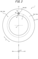
- FIGS. 2 and 3 are diagrams illustrating the first label area 50a from the front.
- FIG. 3 is a side view of the tire 1 viewed from the side of the first side portion 10b1.
- the position of the communication device 40 is represented by a dashed line.
- the first label area 50a and the communication device 40 are disposed at the same position in the tire radial direction B.
- “the first label area 50a and the communication device 40 are disposed at the same position in the tire radial direction B” means that there is at least one virtual circle L1 around the central axis O of the tire 1 that passes through the first label area 50a and the communication device 40 in the side view of the tire 1 (see FIG. 3 ). In other words, it is not limited to a case in which the extension areas of the respective first label area 50a and communication device 40 in the tire radial direction B are completely coincident.
- the first label area 50a and the communication device 40 are disposed at the same position in the tire circumferential direction C.
- “the first label area 50a and the communication device 40 are disposed at the same position in the tire circumferential direction C” means that, in the side view of the tire 1 (see FIG. 3 ), there is at least one virtual straight line L2 that passes through the central axis O of the tire 1 and passes through the first label area 50a and the communication device 40 on one side with respect to the central axis O.
- L2 virtual straight line L2 that passes through the central axis O of the tire 1 and passes through the first label area 50a and the communication device 40 on one side with respect to the central axis O.
- the first label area 50a and the communication device 40 of this embodiment overlap in a tire wall thickness direction D.
- the communication device 40 of this embodiment overlaps with the first label area 50a in the tire wall thickness direction D in its entire extension areas in the tire radial direction B and the tire circumferential direction C.
- the entire communication device 40 of this embodiment overlaps with the first label area 50a in the tire wall thickness direction D.
- only a part of the communication device 40 may overlap with the first label area 50a in the tire wall thickness direction D.
- the entire first label area 50a may overlap with the communication device 40 in the tire wall thickness direction D.
- the contour of the first label area 50a may coincide with the contour of the communication device 40 in the tire wall thickness direction D.
- the entire first label area 50a may overlap with the entire communication device 40 in the tire wall thickness direction D.
- the first label area 50a of this embodiment is disposed in such a position that at least a part of the first label area 50a overlaps with the communication device 40 in the tire wall thickness direction D. Therefore, the position of the communication device 40 can be identified by identifying the first label area 50a from outside the tire 1.
- the first label area 50a of this embodiment includes a light emission area 61.
- the light emission area 61 may be, for example, a phosphorescent area that emits stored light.
- the provision of the light emission area 61 in the first label area 50a allows the first label area 50a to be easily identified from outside the tire 1 in a dark environment, such as at night or in a dark place. Therefore, the position of the communication device 40 can be easily identified in the dark environment.
- the light emission area 61 of the first label area 50a is not particularly limited as long as the light emission area 61 is an area that emits light to the outside.
- the light emission area 61 may be composed of, for example, phosphorescent paint containing a phosphorescent material.
- the light emission area 61 may be formed, for example, by mixing a phosphorescent material into a part of a rubber composition configuring the outer surface of the tire body 10.
- the rubber composition containing the phosphorescent material may be, for example, affixed to an unvulcanized tire and vulcanized together with the unvulcanized tire.
- the rubber composition containing the phosphorescent material may also be, for example, affixed to a tire after vulcanization.
- the light emission area 61 may be formed, for example, by a resin phosphorescent material configuring a part of the outer surface of the tire.
- the resin phosphorescent material may be formed, for example, by carrying a phosphorescent material in void spaces of a foam resin, such as polyurethane foam.
- the resin phosphorescent material may be, for example, affixed to an unvulcanized tire and vulcanized together with the unvulcanized tire.
- the resin phosphorescent material may also be, for example, affixed to a tire after vulcanization.
- the phosphorescent material is not particularly limited, and any known phosphorescent material may be used.
- Examples of the phosphorescent material include, for example, compositions: SrAl2O4: Eu, Dy; Sr4Al14O25: Eu, Dy; SrAl2O4: Eu, Dy + Sr4Al14O25: Eu, Dy; Sr4Al14O25: Eu, Dy + CaAl2O4: Eu, Nd; CaAl2O4: Eu, Nd; ZnS: Cu, Mn, Co; ZnS: Cu; and the like.
- the light emission area 61 of the first label area 50a preferably has a color or shape that can be distinguished from the surroundings. As illustrated in FIG. 1 , the light emission area 61 of this embodiment is provided on a top surface of a convex portion 70, which protrudes outward in the tire width direction A from the surroundings. Thus, the light emission area 61 has a color or shape that can be distinguished from the surroundings, so that the first label area 50a can be easily identified not only in a dark environment but also in a bright environment, for example, during the daytime. In other words, the position of the communication device 40 can be distinguished from outside the tire 1 even in the bright environment.
- the light emission area 61 of this embodiment is provided on the top surface of the convex portion 70, but is not limited to this configuration.
- the light emission area 61 may be provided, for example, on a bottom surface of a concave portion.
- the light emission area 61 may have a different color from the surroundings.
- the "different color” means not only a difference in at least one of hue, brightness, or saturation, but also a difference in pattern, luster, or the like, such that the difference can be visually grasped.
- the coloring of the light emission area 61 can be achieved, for example, by adding pigment together with the phosphorescent material described above, or by using pigment containing the phosphorescent material described above.
- the light emission area 61 is preferably provided at least on the top surface of the convex portion 70. This prevents a reduction in the visibility of the light emission area 61 from the outside, for example, in a case in which the light emission area 61 is covered with mud or the like and is difficult to see from the outside.
- the light emission area 61 provided on the top surface of the convex portion 70 may be composed of, for example, phosphorescent paint laminated on the top surface of the convex portion 70.
- the light emission area 61 provided on the top surface of the convex portion 70 may be realized, for example, by making the convex portion 70 itself of the rubber composition containing the phosphorescent material, the resin phosphorescent material, or the like as described above.
- the first label area 50a of this embodiment preferably includes a non-light emission area 62 surrounded by the light emission area 61.
- the provision of such a non-light emission area 62 emphasizes the contrast between the light emission area 61 and the non-light emission area 62 in a dark environment. Therefore, the visibility of the first label area 50a in the dark environment can be enhanced.
- the entire circumference of the non-light emission area 62 is surrounded by the light emission area 61 in the front view of the first label area 50a (see FIGS. 2 and 3 ). More specifically, the light emission area 61 of the first label area 50a of this embodiment is annular in shape in the front view of the first label area 50a (see FIGS. 2 and 3 ). In other words, the convex portion 70 of this embodiment is annular in shape in the front view of the first label area 50a (see FIGS. 2 and 3 ), and the light emission area 61 is provided on the top surface of this annular convex portion 70.
- the non-light emission area 62 is provided inside the annular light emission area 61 in the front view of the first label area 50a (see FIGS.
- the configuration of the light emission area 61 and the non-light emission area 62 of the first label area 50a is not limited to this.
- the non-light emission area 62 of the first label area 50a can be identified in a dark environment, there may be a position at which no light emission area 61 is provided around the non-light emission area 62.
- Such an aspect includes, for example, a non-light emission area 62 surrounded by an approximately C-shaped light emission area 61 in the front view of the first label area 50a (see FIGS. 2 and 3 ).
- the entire circumference of the non-light emission area 62 is preferably surrounded by the light emission area 61 in the front view of the first label area 50a (see FIGS. 2 and 3 ). This can further emphasize the contrast between the light emission area 61 and the non-light emission area 62 in a dark environment.
- the non-light emission area 62 of the first label area 50a is configured to overlap with the communication device 40 in the tire wall thickness direction D.
- the light emission area 61 of the first label area 50a is configured not to overlap with the communication device 40 in the tire wall thickness direction D.
- the position outside the contour (see the dashed line in FIG. 3 ) of the communication device 40 can be identified by the light emission area 61 in the front view of the first label area 50a (see FIGS. 2 and 3 ). Therefore, the entire communication device 40 can be easily removed from the tire body 10 by using the first label area 50a, for example, at the time of disposal of the tire 1.
- the non-light emission area 62 may have a different color from the light emission area 61.
- the non-light emission area 62 may have a different color from the color of the first side outer surface 14a1 of the first side portion 10b1 located around the first label area 50a. This can enhance the distinguishability of each of the light emission area 61, the non-light emission area 62, and the surroundings of the first label area 50a in a bright environment.
- the non-light emission area 62 of a different color from the light emission area 61 may be configured, for example, by paint containing pigment.
- the non-light emission area 62 of a different color from the light emission area 61 may be formed, for example, by coloring the non-light emission area 62 with a mixture of other pigment than carbon black into a part of the rubber composition composing the outer surface of the tire body 10.
- Such a colored rubber composition may be, for example, affixed to an unvulcanized tire and vulcanized together with the unvulcanized tire.
- the colored rubber composition may also be affixed to a tire after vulcanization, for example.
- the non-light emission area 62 of a different color from the light emission area 61 may be formed of, for example, a resin coloring body that constitutes a part of the outer surface of the tire.
- the resin coloring body may be formed, for example, by carrying pigment in void spaces of a foam resin, such as polyurethane foam.
- the resin coloring body may be, for example, affixed to an unvulcanized tire and vulcanized together with the unvulcanized tire.
- the resin coloring body may also be affixed to a tire after vulcanization, for example.
- the non-light emission area 62 may be provided on a fine uneven surface.
- the fine uneven surface may have, for example, a base surface and a plurality of ridges 68 with a height of 0.1 to 1.0 mm that is arranged in parallel on the base surface.
- the distance between the tops of two adjacent ridges 68 is preferably 0.3 to 1.5 mm, for example.
- the tire body 10 of this embodiment includes a cylindrical base protrusion portion 69, which protrudes on the outer surface of the first side portion 10b1, and the annular convex portion 70, which protrudes from an outer edge of a top surface of the base protrusion portion 69.
- the first label area 50a of this embodiment is constituted of the light emission area 61, which is provided on the top surface of the convex portion 70, and the non-light emission area 62, which is provided on the top surface of the base protrusion portion 69 inside the convex portion 70.
- not only the light emission area 61 but also the non-light emission area 62 is provided on the top surface of the portion protruding from the surroundings of the first label area 50a.
- Such a first label area 50a can be achieved, for example, by laminating paint containing a phosphorescent material on the top surface of the convex portion 70 and laminating paint containing pigment on the top surface of the base protrusion portion 69 inside the convex portion 70.
- a component corresponding to the base protrusion portion 69 and a component corresponding to the convex portion 70 may be formed separately and then laminated to form a single unit.
- the component corresponding to the base protrusion portion 69 may be formed of, for example, the above-described colored rubber composition, resin colored material, or the like.
- the component corresponding to the convex portion 70 may be formed of, for example, the above-described rubber composition containing the phosphorescent material, the resin phosphorescent material, or the like.
- the second label area 50b is provided on the second side outer surface 14a2 of the second side portion 10b2 of the tire body 10.
- the second label area 50b is configured to be distinguishable from the first label area 50a.
- the second label area 50b of this embodiment is constituted only of a light emission area 81.
- the second label area 50b of this embodiment is the light emission area 81 in the entirety of its contour in the front view, and does not include a non-light emission area.
- first label area 50a and the second label area 50b distinguishable, as described above, it is possible to prevent confusion between the first label area 50a and the second label area 50b and to distinguish between information indicated by the first label area 50a and information indicated by the second label area 50b.
- the provision of the second label area 50b allows the position of the communication device 40 in the tire circumferential direction C to be identified even from the side of the second side portion 10b2, in contrast to the case of providing only the first label area 50a. Therefore, for example, even when the tire 1 is mounted on a vehicle with the first side portion 10b1 located inside the vehicle, and the first label area 50a is not visible from outside the vehicle, the position of the communication device 40 can be narrowed down based on the second label area 50b on the second side portion 10b2. The position of the communication device 40 can be easily identified regardless of the orientation of the first side portion 10b1 of the tire body 10 mounted on the vehicle.
- the second label area 50b of this embodiment indicates the position of the communication device 40 in the tire circumferential direction C, but is not limited to this configuration.
- the second label area 50b may indicate the position of the communication device 40 in the tire radial direction B.
- the second label area 50b and the communication device 40 may be disposed at the same position in the tire radial direction B.
- “the second label area 50b and the communication device 40 are disposed at the same position in the tire radial direction B" is the same as the relationship described above in which the first label area 50a and the communication device 40 are disposed at the same position in the tire radial direction B.
- the second label area 50b may not indicate the position of the communication device 40 in the tire radial direction B and the tire circumferential direction C, but only indicate that the communication device 40 is in/on the first side portion 10b1.
- the second label area 50b may be a label indicating that there is no communication device 40 in/on the second side portion 10b2.
- the second label area 50b is not particularly limited as long as the second label area 50b indicates some location information on the communication device 40.
- the light emission area 81 of the second label area 50b preferably has a color or shape that can be distinguished from the surroundings. As illustrated in FIG. 1 , the light emission area 81 of this embodiment is provided on a top surface of a convex portion 71, which protrudes outward in the tire width direction A from the surroundings. Thus, due to the light emission area 81 having the color or the shape that can be distinguished from the surroundings, the second label area 50b can be easily identified not only in a dark environment but also in a bright environment, for example, during the daytime.
- the light emission area 81 of this embodiment is provided on the top surface of the convex portion 71, but is not limited to this configuration.
- the light emission area 81 may be provided, for example, on a bottom surface of a concave portion.
- the light emission area 81 may have a different color from its surroundings.
- the light emission area 81 is preferably provided at least on the top surface of the convex portion 71.
- the light emission area 81 may be formed of, for example, paint containing a phosphorescent material, or the like, by the same method as for the light emission area 61 of the first label area 50a as described above.
- the light emission area 81 of the second label area 50b of this embodiment is provided on the entire top surface of the cylindrical convex portion 71, but the aspect thereof is not particularly limited as long as the light emission area 81 can be distinguished from the light emission area 61 of the first label area 50a in a dark environment.
- the second label area 50b is configured by the top surface of the cylindrical convex portion 71, but the aspect thereof is not particularly limited as long as the second label area 50b can be distinguished from the first label area 50a in a bright environment.
- the aspect of the second label area 50b is not particularly limited as long as the second label area 50b can be distinguished from the first label area 50a in the dark and bright environments.
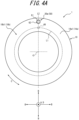
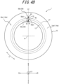
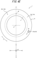
- FIGS. 4A to 4E are side views of the tire 1 viewed from the side of the first side portion 10b1.
- the position of the communication device 40 embedded in the first side portion 10b1 is represented by a dashed line.
- the first label area 50a illustrated in FIG. 4A indicates the position of the communication device 40 in the tire circumferential direction C.
- the first label area 50a illustrated in FIG. 4A does not indicate the position of the communication device 40 in the tire radial direction B.
- the first label area 50a and the communication device 40 illustrated in FIG. 4A are disposed at the same position in the tire circumferential direction C, but are not disposed at the same position in the tire radial direction B.
- the position of the communication device 40 in the tire circumferential direction C can be identified.
- the first label area 50a illustrated in FIG. 4B indicates the position of the communication device 40 in the tire radial direction B. However, the first label area 50a illustrated in FIG. 4B does not indicate the position of the communication device 40 in the tire circumferential direction C. In other words, the first label area 50a and the communication device 40 illustrated in FIG. 4B are disposed at the same position in the tire radial direction B, but are not disposed at the same position in the tire circumferential direction C. According to the first label area 50a illustrated in FIG. 4B , the position of the communication device 40 in the tire radial direction B can be identified.
- the first label areas 50a illustrated in FIG. 4C indicate the position of the communication device 40 in the tire circumferential direction C. However, the first label areas 50a illustrated in FIG. 4C do not indicate the position of the communication device 40 in the tire radial direction B. More specifically, the first label areas 50a illustrated in FIG. 4C indicate a predetermined range in the tire circumferential direction C. The first label areas 50a illustrated in FIG. 4C indicate the range in the tire circumferential direction C, in which the central angle around the central axis O of the tire 1 is "0". The communication device 40 is located within the range in the tire circumferential direction C indicated by the first label areas 50a. According to the first label areas 50a illustrated in FIG. 4C , the range in the tire circumferential direction C, in which the communication device 40 is located, can be identified.
- each first label area 50a in the front view is not limited to the triangular shape illustrated in FIG. 4C .
- the triangular shape illustrated in FIG. 4C is preferable as the external shape of each first label area 50a in the front view. This makes it further easier to visually grasp the range in the tire circumferential direction C indicated by the two first label areas 50a.
- the first label areas 50a illustrated in FIG. 4D indicate the position of the communication device 40 in the tire radial direction B and in the tire circumferential direction C. More specifically, the first label areas 50a illustrated in FIG. 4D are disposed at the same position as the communication device 40 in the tire circumferential direction C.
- the first label areas 50a illustrated in FIG. 4D also indicate a predetermined range in the tire radial direction B.
- the communication device 40 is located within the range in the tire radial direction B indicated by the first label areas 50a. According to the first label areas 50a illustrated in FIG. 4D , it is possible to identify the position of the communication device 40 in the tire circumferential direction C, as well as the range in the tire radial direction B in which the communication device 40 is located.
- two of the first label areas 50a disposed at different positions in the tire radial direction B indicate the range in the tire radial direction B, in which the communication device 40 is located.
- Each first label area 50a is approximately triangular in shape in the front view.
- the first label areas 50a are disposed such that a vertex 50a1 of one of the first label areas 50a faces a vertex 50a1 of the other first label area 50a in the tire radial direction B.
- the respective first label areas 50a preferably include the vertices 50a1 facing each other in the tire radial direction B.
- each first label area 50a in the front view is not limited to the triangular shape illustrated in FIG. 4D .
- the triangular shape illustrated in FIG. 4D is preferable as the external shape of each first label area 50a in the front view. This makes it further easier to visually grasp the range in the tire radial direction B indicated by the two first label areas 50a.
- the two first label areas 50a are disposed at the same position as the communication device 40 in the tire circumferential direction C, but may be disposed at different positions. However, as illustrated in FIG. 4D , the two first label areas 50a are preferably disposed at the same position as the communication device 40 in the tire circumferential direction C. This makes it possible to easily identify the position of the communication device 40 in the tire circumferential direction C, in addition to the position of the communication device 40 in the tire radial direction B.
- the first label area 50a illustrated in FIG. 4E does not indicate the position of the communication device 40 in the tire radial direction B and the tire circumferential direction C, but only indicates that the communication device 40 is located in/on the first side portion 10b1.
- the first label area 50a illustrated in FIG. 4E may only indicate that the communication device 40 is located in/on the first side portion 10b1, among the first side portion 10b1 and the second side portion 10b2 (see FIG. 1 ).
- the first label area 50a preferably indicates the position of the communication device 40, which is provided in/on the first side portion 10b1, in at least one of the tire radial direction B or the tire circumferential direction C.
- FIG. 5 is a cross-sectional view of the tire 100 in the tire width direction.
- the tire 100 of this embodiment differs from the tire 1 (see FIG. 1 ) described above only in the position of the communication device 40. Therefore, the position of the communication device 40 and information indicated by the first and second label areas 50a and 50b will be described here, and a description of the configuration common to the tire 1 of the first embodiment is omitted.
- the tire 100 includes the communication device 40 embedded in the tread portion 10a of the tire body 10.
- the communication device 40 of this embodiment is embedded within the tread portion 10a, but may be mounted on the tread inner surface 13b.
- the communication device 40 is disposed on one side in the tire width direction A with respect to the tire equatorial plane CL.
- one side in the tire width direction A with respect to the tire equatorial plane CL, on which the communication device 40 is disposed is hereinafter simply referred to as "communication device 40 side in the tire width direction A”.
- the other side in the tire width direction A with respect to the tire equatorial plane CL, on which the communication device 40 is not disposed is simply referred to as "opposite side of the communication device 40 side in the tire width direction A".
- the configuration of the first label area 50a of this embodiment is the same as that of the first embodiment described above, so a description is omitted here.
- the first label area 50a of this embodiment does not overlap with the communication device 40 in the tire wall thickness direction D.
- the first label area 50a of this embodiment indicates the communication device 40 side in the tire width direction A. In other words, due to the first label area 50a, it is possible to identify which side in the tire width direction A the communication device 40 is located with respect to the tire equatorial plane CL.
- the first label area 50a of this embodiment is preferably disposed at the same position as the communication device 40 in the tire circumferential direction C. This makes it possible to identify, using the first label area 50a, the position of the communication device 40 in the tire circumferential direction C.
- the configuration of the second label area 50b of this embodiment is the same as that of the first embodiment described above, so a description is omitted here.
- the second label area 50b of this embodiment indicates the opposite side of the communication device 40 side in the tire width direction A. In other words, due to the second label area 50b, it is possible to identify which side in the tire width direction A the communication device 40 is located with respect to the tire equatorial plane CL.
- the second label area 50b of this embodiment is preferably disposed at the same position as the communication device 40 in the tire circumferential direction C. This makes it possible to identify, from the second label area 50b, the position of the communication device 40 in the tire circumferential direction C.
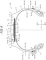
- FIG. 6 is a cross-sectional view of the tire 200 in the tire width direction.
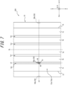
- FIG. 7 is a part of a development diagram of the tread outer surface 13a of the tire 200.
- the position of the communication device 40 is represented by the dashed line.
- the tire 200 of this embodiment differs in its configuration in terms of the position of the communication device 40 and the provision of a third label area 50c. Therefore, the differences will be mainly described here, and a description of a configuration common to the tire 1 of the first embodiment and the tire 100 of the second embodiment is omitted.
- the tire 200 includes the communication device 40 mounted on the tread inner surface 13b of the tire body 10.
- the communication device 40 of this embodiment is disposed on one side in the tire width direction A with respect to the tire equatorial plane CL.
- one side in the tire width direction A with respect to the tire equatorial plane CL, on which the communication device 40 is disposed is hereinafter simply referred to as "communication device 40 side in the tire width direction A”.
- the other side in the tire width direction A with respect to the tire equatorial plane CL, on which the communication device 40 is not disposed, is simply referred to as "opposite side of the communication device 40 side in the tire width direction A".
- first and second label areas 50a and 50b of this embodiment is the same as that of the first and second embodiments described above, so a description is omitted here.
- Information indicated by the first and second label areas 50a and 50b of this embodiment is also the same as that of the second embodiment described above, so a description is omitted here.
- the tire body 10 of the tire 200 of this embodiment may not include any one or both of the first label area 50a and the second label area 50b.
- the provision of the first label area 50a and the second label area 50b in the tire body 10 of the tire 200 allows the position of the communication device 40 to be identified more easily.
- the third label area 50c is disposed on the tread outer surface 13a, which is an outer surface of the tread portion 10a of the tire body 10.
- the third label area 50c and the communication device 40 are disposed at the same position in the tire width direction A.
- “the third label area 50c and the communication device 40 are disposed at the same position in the tire width direction A” means that there is at least one virtual line L5 that is in parallel to the tire circumferential direction C and passes through the third label area 50c and the communication device 40 in the developed view (see FIG. 7 ) of the tread outer surface 13a of the tire 200.
- the third label area 50c and the communication device 40 are disposed at the same position in the tire circumferential direction C.
- “the third label area 50c and the communication device 40 are disposed at the same position in the tire circumferential direction C” means that there is at least one virtual line L6 that is in parallel to the tire width direction A and passes through the third label area 50c and the communication device 40 in the developed view (see FIG. 7 ) of the tread outer surface 13a of the tire 200.
- the third label area 50c and the communication device 40 of this embodiment overlap in the tire wall thickness direction D.
- the communication device 40 overlaps with the third label area 50c in the tire wall thickness direction D in its entire extension areas in the tire width direction A and in the tire circumferential direction C.
- the entire communication device 40 of this embodiment overlaps with the third label area 50c in the tire wall thickness direction D.
- only a part of the communication device 40 may overlap with the third label area 50c in the tire wall thickness direction D.
- the entire third label area 50c may overlap with the communication device 40 in the tire wall thickness direction D.
- the contour of the third label area 50c may coincide with the contour of the communication device 40 in the tire wall thickness direction D.
- the entire third label area 50c may overlap with the entire communication device 40 in the tire wall thickness direction D.
- the third label area 50c of this embodiment is disposed in such a position that at least a part of the third label area 50c overlaps with the communication device 40 in the tire wall thickness direction D. Therefore, the position of the communication device 40 can be identified by identifying the third label area 50c from outside the tire 200.
- the third label area 50c of this embodiment includes a light emission area 91.
- the details of the light emission area 91 are similar to those of the light emission area 61 of the first label area 50a described above, except that the outer shape of the third label area 50c is approximately rectangular in the front view (see FIG. 7 ), and that the third label area 50c is formed on a bottom surface of the outer circumferential groove 7b1, so a description is omitted here.
- the light emission area 91 of the third label area 50c may be provided, for example, on a top surface of a convex portion provided on the bottom surface of the outer circumferential groove 7b 1.
- the light emission area 91 of the third label area 50c may have, for example, a color that can be distinguished from the surroundings at the bottom surface of the outer circumferential groove 7b1.
- the third label area 50c of this embodiment preferably includes a non-light emission area 92 surrounded by the light emission area 91.
- the details of the non-light emission area 92 are similar to those of the non-light emission area 62 of the first label area 50a described above, except that the outer shape of the third label area 50c is approximately rectangular in the front view (see FIG. 7 ), and that the third label area 50c is formed on the bottom surface of the outer circumferential groove 7b1, so a description is omitted here.
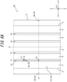
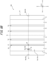
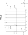
- FIGS. 8A to 8E are each a part of a development diagram of the tread outer surface 13a of the tire 200.
- the position of the communication device 40 mounted on the tread inner surface 13b is represented by a dashed line.
- the third label area 50c illustrated in FIG. 8A indicates the position of the communication device 40 in the tire width direction A. However, the third label area 50c illustrated in FIG. 8A does not indicate the position of the communication device 40 in the tire circumferential direction C. In other words, the third label area 50c and the communication device 40 illustrated in FIG. 8A are disposed at the same position in the tire width direction A, but are not disposed at the same position in the tire circumferential direction C. According to the third label area 50c illustrated in FIG. 8A , the position of the communication device 40 in the tire width direction A can be identified.
- the third label area 50c illustrated in FIG. 8B indicates the position of the communication device 40 in the tire circumferential direction C.
- the third label area 50c illustrated in FIG. 8B does not indicate the position of the communication device 40 in the tire width direction A.
- the third label area 50c and the communication device 40 illustrated in FIG. 8B are disposed at the same position in the tire circumferential direction C, but are not disposed at the same position in the tire width direction A.
- the position of the communication device 40 in the tire circumferential direction C can be identified.
- the third label areas 50c illustrated in FIG. 8C indicate the position of the communication device 40 in the tire width direction A. However, the third label areas 50c illustrated in FIG. 8C do not indicate the position of the communication device 40 in the tire circumferential direction C. More specifically, the third label areas 50c illustrated in FIG. 8C indicate a predetermined range in the tire width direction A. The communication device 40 is located within the range in the tire width direction A indicated by the third label areas 50c. According to the third label areas 50c illustrated in FIG. 8C , the range in the tire width direction A, in which the communication device 40 is located, can be identified.
- two of the third label areas 50c disposed at different positions in the tire width direction A indicate the range in the tire width direction A, in which the communication device 40 is located.
- Each third label area 50c is approximately triangular in shape in the front view (see FIG. 7 ).
- the third label areas 50c are disposed such that a vertex 50c1 of one of the third label areas 50c faces a vertex 50c1 of the other third label area 50c in the tire width direction A.
- the respective third label areas 50c preferably include the vertices 50c1 facing each other in the tire width direction A.
- each third label area 50c in the front view is not limited to the triangular shape illustrated in FIG. 8C .
- the triangular shape illustrated in FIG. 8C is preferable as the external shape of each third label area 50c in the front view. This makes it further easier to visually grasp the range (the range between virtual straight lines L7 and L8 represented by long and short dashed lines in FIG. 8C ) in the tire width direction A indicated by the two third label areas 50c.
- the third label areas 50c illustrated in FIG. 8D indicate the position of the communication device 40 in the tire circumferential direction C. However, the third label areas 50c illustrated in FIG. 8D do not indicate the position of the communication device 40 in the tire width direction A. More specifically, the third label areas 50c illustrated in FIG. 8D indicate a predetermined range in the tire circumferential direction C. The communication device 40 is located within the range in the tire circumferential direction C indicated by the third label areas 50c. According to the third label areas 50c illustrated in FIG. 8D , the range in the tire circumferential direction C, in which the communication device 40 is located, can be identified.
- the two third label areas 50c disposed at different positions in the tire circumferential direction C indicate the range in the tire circumferential direction C, in which the communication device 40 is located.
- Each third label area 50c is approximately triangular in shape in the front view (see FIG. 7 ).
- the third label areas 50c are disposed such that a vertex 50c1 of one of the third label areas 50c faces a vertex 50c1 of the other third label area 50c in the tire circumferential direction C.
- the respective third label areas 50c preferably include the vertices 50c1 facing each other in the tire circumferential direction C.
- each third label area 50c in the front view is not limited to the triangular shape illustrated in FIG. 8D .
- the triangular shape illustrated in FIG. 8D is preferable as the external shape of each third label area 50c in the front view. This makes it further easier to visually grasp the range (the range between virtual straight lines L9 and L10 represented by long and short dashed lines in FIG. 8D ) in the tire circumferential direction C indicated by the two third label areas 50c.
- the two third label areas 50c are disposed at different positions from the communication device 40 in the tire width direction A, but may be disposed at the same position. This makes it possible to easily identify the position of the communication device 40 in the tire width direction A, in addition to the position of the communication device 40 in the tire circumferential direction C.
- the third label area 50c illustrated in FIG. 8E does not indicate the position of the communication device 40 in the tire width direction A and the tire circumferential direction C, but indicates the communication device 40 side of the tread portion 10a in the tire width direction A.
- the third label area 50c illustrated in FIG. 8E may indicate one side of the tread portion 10a in the tire width direction A, on which the communication device 40 is disposed, with respect to the tire equatorial plane CL.
- the third label area 50c preferably indicates the position of the communication device 40 provided in the tread portion 10a in at least one of the tire radial direction B or the tire circumferential direction C.
- the position of the communication device 40 can be easily identified even in a dark environment.
- the light emission area of the label area 50 is preferably disposed at the same position as the communication device 40 in at least one of the tire width direction A, the tire radial direction B, or the tire circumferential direction C. This allows the position of the communication device 40 to be identified more easily in a dark environment based on the light emission area of the label area 50.
- FIGS. 6 , 7 , and 8A illustrate the examples in which the light emission area 91 of the third label area 50c is disposed at the same position as the communication device 40 in the tire width direction A. In this specification, FIGS.
- FIGS. 1 to 3 and 4B illustrate the examples in which the light emission area 61 of the first label area 50a and the light emission area 81 of the second label area 50b are disposed at the same position as the communication device 40 in the tire radial direction B. Furthermore, in this specification, the light emission area 61 of the first label area 50a and the light emission area 81 of the second label area 50b illustrated in FIGS. 1 to 3 , 4A , 4D , 5 , 6 , 7 , and 8A to 8E are disposed at the same position as the communication device 40 in the tire circumferential direction C. In this specification, the light emission area 91 of the third label area 50c illustrated in FIGS. 6 , 7 , and 8B is disposed at the same position as the communication device 40 in the tire circumferential direction C.
- the present disclosure relates to a tire.
Landscapes
- Engineering & Computer Science (AREA)
- Mechanical Engineering (AREA)
- Tires In General (AREA)
Abstract
Description
- The present disclosure relates to a tire.
- Tires with communication devices such as RF tags embedded within are known. Patent Literature (PTL) 1 discloses this type of tire.
- PTL 1:
JP 2004-148953 A - It is difficult to distinguish the position of a communication device embedded within a tire or mounted on an inner surface of a tire from outside the tire at night or in a dark surrounding environment.
- It would be helpful to provide a tire in which the position of a communication device can be distinguished from outside the tire in a dark surrounding environment.
- A tire, as a first aspect of the present disclosure, includes a tire body and a communication device embedded within the tire body or mounted on an inner surface of the tire body. The tire includes a label area that is located on an outer surface of the tire body and indicates the position of the communication device. The label area includes a light emission area.
- According to the present disclosure, it is possible to provide a tire in which the position of a communication device can be distinguished from outside the tire in a dark surrounding environment.
- In the accompanying drawings:
-
FIG. 1 is a cross-sectional view of a tire as an embodiment of the present disclosure in a tire width direction; -
FIG. 2 is a front view of a first label area of the tire illustrated inFIG. 1 ; -
FIG. 3 is a side view of the tire illustrated inFIG. 1 , viewed from the side of a first side portion; -
FIG. 4A is a diagram illustrating a variation of the first label area illustrated inFIG. 1 ; -
FIG. 4B is a diagram illustrating a variation of the first label area illustrated inFIG. 1 ; -
FIG. 4C is a diagram illustrating a variation of the first label area illustrated inFIG. 1 ; -
FIG. 4D is a diagram illustrating a variation of the first label area illustrated inFIG. 1 ; -
FIG. 4E is a diagram illustrating a variation of the first label area illustrated inFIG. 1 ; -
FIG. 5 is a cross-sectional view of a tire as an embodiment of the present disclosure in the tire width direction; -
FIG. 6 is a cross-sectional view of a tire as an embodiment of the present disclosure in the tire width direction; -
FIG. 7 is a part of a development diagram of a tread outer surface of the tire illustrated inFIG. 6 ; -
FIG. 8A is a diagram illustrating a variation of a third label area illustrated inFIG. 6 ; -
FIG. 8B is a diagram illustrating a variation of the third label area illustrated inFIG. 6 ; -
FIG. 8C is a diagram illustrating a variation of the third label area illustrated inFIG. 6 ; -
FIG. 8D is a diagram illustrating a variation of the third label area illustrated inFIG. 6 ; and -
FIG. 8E is a diagram illustrating a variation of the third label area illustrated inFIG. 6 . - Embodiments of a tire according to the present disclosure will be exemplarily described below with reference to the drawings. In the drawings, the same reference signs denote common components. In this specification, a tire width direction refers to a direction parallel to the central axis of the tire. A tire radial direction refers to a radial direction that is orthogonal to the central axis of the tire and centered on the central axis. A tire circumferential direction refers to a direction in which the tire rotates about the central axis of the tire.
- In this specification, a "tread outer surface" means an outer circumferential surface throughout the entire circumference of the tire that is in contact with a road surface when the tire mounted on a rim and filled with a specified internal pressure is rotated under a maximum load (hereinafter also referred to as "maximum load condition"). In addition, "tread ends" mean outer ends of the tread outer surface in the tire width direction.
- In this specification, the "rim" means a standard rim (Measuring Rim in ETRTO's STANDARDS MANUAL and Design Rim in TRA's YEAR BOOK) of an applicable size conformable to industrial standards valid for regions in which tires are produced and used, as described in or to be described in JATMA YEAR BOOK of the Japan Automobile Tyre Manufacturers Association, Inc. (JATMA) in Japan, STANDARDS MANUAL of the European Tyre and Rim Technical Organisation (ETRTO) in Europe, YEAR BOOK of the Tire and Rim Association, Inc. (TRA) in the United States, or the like, but in the case of a size that is not listed in such industrial standards, a rim with a width corresponding to a bead width of the tire. The "rim" may be of a size that may be included in the above industrial standards in the future, as well as a current size. Examples of the "size that is included in the future" may be sizes listed as "FUTURE DEVELOPMENTS" in the 2013 edition of STANDARDS MANUAL of the ETRTO.
- In this specification, the "specified internal pressure" means an air pressure (maximum air pressure) corresponding to a maximum load capacity of a single wheel in an applicable size and ply rating as described in the above industrial standards such as JATMA YEAR BOOK, but in the case of a size that is not listed in the above industry standards, an air pressure (maximum air pressure) corresponding to a maximum load capacity specified for each vehicle on which the tire is mounted. In this specification, the "maximum load" means a load corresponding to the maximum load capacity of the tire of an applicable size listed in the above industrial standards, but in the case of a size that is not listed in the above industrial standards, a load corresponding to the maximum load capacity specified for each vehicle on which the tire is mounted.
- A pneumatic tire 1 (hereinafter simply referred to as "tire 1") as an embodiment of the tire according to the present disclosure will be exemplarily described below with reference to the drawings. Unless otherwise stated, the tire 1 described below is assumed to mean a tire 1 that is mounted on a rim, filled with a specified internal pressure, and in a maximum load condition. The type of tire 1 is not particularly limited, and may be, for example, a tire for trucks or buses, or a tire for passenger cars.
-
FIG. 1 is a cross-sectional view of the tire 1 in a tire width direction. As illustrated inFIG. 1 , the tire 1 includes atire body 10 and acommunication device 40. - The
tire body 10 includes atread portion 10a, a first side portion 10b1, and a second side portion 10b2. The first side portion 10b1 extends from one end of thetread portion 10a in a tire width direction A toward an inner side B2 in a tire radial direction B. The second side portion 10b2 extends from the other end of thetread portion 10a in the tire width direction A toward the inner side B2 in the tire radial direction B. Hereinafter, the first side portion 10b1 and the second side portion 10b2 are simply described as "side portions 10b" when not specifically distinguished. - The
side portions 10b each have asidewall portion 11 and abead portion 12. Thesidewall portion 11 is connected to the end of thetread portion 10a in the tire width direction A and extends toward the inner side B2 in the tire radial direction B. Thebead portion 12 is connected to an end of thesidewall portion 11 on the inner side B2 in the tire radial direction B. - More specifically, the
tire body 10 of this embodiment includesbead cores 2,bead fillers 3, acarcass 4,belts 5, treadrubber 7,side rubber 8, and aninner liner 9. However, thetire body 10 may include other components, not limited to the above components. - The
bead cores 2 and thebead fillers 3 are embedded in thebead portions 12 of theside portions 10b. Eachbead core 2 includes a bead cord that is surrounded by a rubber coating. The bead cord is formed of a steel cord. Eachbead filler 3 is made of rubber and is located on an outer side B 1 in the tire radial direction B with respect to thebead core 2. - The
carcass 4 extends toroidally between the pair ofbead portions 12, which is constituted of thebead portion 12 of the first side portion 10b1 and thebead portion 12 of the second side portion 10b2, more specifically between the pair ofbead cores 2. Specifically, thecarcass 4 of this embodiment includes acarcass ply 4a. Thecarcass ply 4a is folded from the inside to the outside in the tire width direction A around therespective bead cores 2. Thecarcass ply 4a may have a plurality of ply cords arranged parallel to each other and coating rubber that coats the plurality of ply cords. Thecarcass 4 of this embodiment includes only onecarcass ply 4a, but may include two or more carcass plies 4a. The plurality of ply cords of thecarcass ply 4a may be arranged at an angle of, for example, 75° to 90° with respect to a tire circumferential direction C. The ply cords of thecarcass ply 4a can be, for example, metal cords such as steel cords. - More specifically, the
carcass ply 4a of this embodiment has a body part 4a1 located between the pair ofbead cores 2, and folded parts 4a2 that are connected to the body part 4a1 and folded from the inside to the outside in the tire width direction A around therespective bead cores 2. The above-describedbead fillers 3 are each located between the body part 4a1 and each folded part 4a2 of thecarcass ply 4a. - The
belts 5 are embedded in thetread portion 10a. Thetire body 10 of this embodiment has four of thebelts 5 on the outer side B 1 of a crown part of thecarcass 4 in the tire radial direction B. The fourbelts 5 of this embodiment include afirst belt 5a, asecond belt 5b, athird belt 5c, and afourth belt 5d. Hereafter, thefirst belt 5a, thesecond belt 5b, thethird belt 5c, and thefourth belt 5d are simply referred to as "belts 5" when not specifically distinguished. Thefirst belt 5a is located at the most inner side B2 in the tire radial direction B, among thefirst belt 5a, thesecond belt 5b, thethird belt 5c, and thefourth belt 5d. Thefourth belt 5d is located at the most outer side B 1 in the tire radial direction B, among thefirst belt 5a, thesecond belt 5b, thethird belt 5c, and thefourth belt 5d. Thesecond belt 5b and thethird belt 5c are located between thefirst belt 5a and thefourth belt 5d in the tire radial direction B. More specifically, thethird belt 5c is located on the outer side B1 of thesecond belt 5b in the tire radial direction B. - In this embodiment, the
first belt 5a, thesecond belt 5b, thethird belt 5c, and thefourth belt 5d constitute four belt layers. Specifically, thefirst belt 5a forms a first belt layer 20a located at the most inner side B2 in the tire radial direction B. Thefourth belt 5d forms afourth belt layer 20d located at the most outer side B1 in the tire radial direction B. Thesecond belt 5b forms asecond belt layer 20b. Thethird belt 5c forms athird belt layer 20c. - Each
belt 5 may include a plurality of belt cords arranged in parallel to each other and coating rubber that coats the plurality of belt cords. The first to fourth belt layers 20a to 20d are inclined belt layers in which the belt cords form a predetermined angle with respect to the tire circumferential direction C. The belt cords of two belt layers adjacent in the tire radial direction B, among the first to fourth belt layers 20a to 20d, may be inclined in the same direction or in opposite directions with respect to the tire circumferential direction C. - The material of the belt cords of the
belts 5 is not particularly limited. The belt cords of thebelts 5 may be, for example, metal cords or organic fiber cords. A rubber composition used for the coating rubber of thebelts 5 is not particularly limited. - As illustrated in
FIG. 1 , thetread rubber 7 is located on the outer side B1 of the crown part of the body part 4a1 of thecarcass ply 4a and on the outer side B 1 of the first tofourth belts 5a to 5d, which constitute the first to fourth belt layers 20a to 20d, in the tire radial direction B. A treadouter surface 13a, which is an outer surface of thetread portion 10a of this embodiment, is composed of thetread rubber 7. In the treadouter surface 13a, as illustrated inFIG. 1 , there are formed two inner circumferential grooves 7a1, which zone acenter land area 7a through which a tire equatorial plane CL passes, and two outer circumferential grooves 7b1, which are located outside the inner circumferential grooves 7a1 in the tire width direction A and zoneintermediate land areas 7b each between the inner circumferential groove 7a1 and the outer circumferential groove 7b1. In the treadouter surface 13a of this embodiment,shoulder land areas 7c are zoned each between the outercircumferential groove 7b 1 and atread end 15 located outside the outer circumferential groove 7b1 in the tire width direction A. In the treadouter surface 13a, for example, width directional grooves extending in the tire width direction A or the like may be formed. - The
side rubber 8 is disposed outside the body part 4a1 and the folded parts 4a2 of thecarcass ply 4a in the tire width direction A. Sideouter surfaces 14a, which are outer surfaces of theside portions 10b of this embodiment, are composed of theside rubber 8. Ends of theside rubber 8 on the outer side B1 in the tire radial direction B are connected to ends of the above-describedtread rubber 7 in the tire width direction A. - Thus, in this embodiment, an outer surface of the
tire body 10 includes the treadouter surface 13a and the sideouter surfaces 14a, which are connected to the treadouter surface 13a. Thetire body 10 includes, on its outer surface,label areas 50 that indicate the position of acommunication device 40 described below. The details of thedistinction areas 50 will be described below (seeFIGS. 2 ,3 , and the like). - The
inner liner 9 covers a tire inner surface side of the body part 4a1 of thecarcass ply 4a, and constitutes an inner surface of thetire body 10. The inner surface of thetire body 10 includes a treadinner surface 13b, which is an inner surface of thetread portion 10a, and sideinner surfaces 14b, which are inner surfaces of theside portions 10b. Theinner liner 9 is laminated on the tire inner surface side of the body part 4a1 of thecarcass ply 4a. Theinner liner 9 may be formed of, for example, butyl rubber with low air permeability. - As illustrated in
FIG. 1 , thecommunication device 40 is embedded within thetire body 10. However, thecommunication device 40 may be mounted on the inner surface of thetire body 10. The inner surface of thetire body 10 on which thecommunication device 40 is mounted may be the treadinner surface 13b, a first side inner surface 14b1, which is an inner surface of thefirst side portion 10b 1, or a second side inner surface 14b2, which is an inner surface of the second side portion 10b2. - As illustrated in
FIG. 1 , thecommunication device 40 of this embodiment is embedded within theside portion 10b of thetire body 10. More specifically, thecommunication device 40 of this embodiment is embedded within the first side portion 10b1 of thetire body 10. Thecommunication device 40 of this embodiment is embedded, in the first side portion 10b1, between the body part 4a1 of thecarcass 4 and theside rubber 8. However, thecommunication device 40 may be embedded in another location in the first side portion 10b1. As described above, thecommunication device 40 may also be mounted on the inner surface of the first side portion 10b1 (see the position represented by the alternate long and short dashed line with the reference sign "40" inFIG. 1 ). - Furthermore, the
communication device 40 may be disposed in another location than the first side portion 10b1. Thecommunication device 40 may be, for example, embedded within the second side portion 10b2 of thetire body 10, or mounted on the inner surface of the second side portion 10b2. Thecommunication device 40 may be embedded within thetread portion 10a of the tire body 10 (seeFIG. 5 ), or may be mounted on the inner surface of thetread portion 10a (seeFIG. 6 ). - The configuration of the
communication device 40 is not particularly limited as long as thecommunication device 40 is configured to be able to wirelessly communicate with a predetermined device outside thetire body 10. An example of thecommunication device 40 is an RF tag. The RF tag, as thecommunication device 40, can wirelessly communicate with a reader/writer located outside thetire body 10. The RF tag may be, for example, a passive RF tag that is operated by electric power supplied from the reader/writer located outside thetire body 10. Specifically, the RF tag, as thecommunication device 40, can receive, at an antenna of the RF tag, information transmitted from an antenna of the reader/writer in the form of a radio wave or a magnetic field. Due to rectification (in the case of the radio wave) or resonance (in the case of the magnetic field), electric power is generated at the antenna of the RF tag, and a memory and a controller of the RF tag perform predetermined operations. The controller of the RF tag can, for example, read out information from the memory of the RF tag and transmit the information (back) to the reader/writer from the antenna in the form of a radio wave or a magnetic field. The antenna of the reader/writer receives the radio wave or the magnetic field from the RF tag. A controller of the reader/writer retrieves the received information to acquire the information stored in the memory of the RF tag. The above-described memory and controller of the RF tag may be configured, for example, in an integrated circuit (IC chip) including a non-volatile memory. - The
communication device 40 may be embedded within thetire body 10, for example, as a covered communication device whose periphery is covered in advance with covering rubber. In such a case, the covering rubber that covers the periphery of thecommunication device 40 may be colored differently from adjacent portions of thetire body 10. - As illustrated in
FIG. 1 , thelabel areas 50 indicating the position of thecommunication device 40 are provided on the outer surfaces of thetire body 10. Thelabel areas 50 of this embodiment are provided on the sideouter surfaces 14a, which are the outer surfaces of theside portions 10b of thetire body 10. More specifically, thetire body 10 of this embodiment includes afirst label area 50a provided on a first side outer surface 14a1, which is an outer surface of the first side portion 10b1, and asecond label area 50b provided on a second side outer surface 14a2, which is an outer surface of the second side portion 10b2. -
FIGS. 2 and3 are diagrams illustrating thefirst label area 50a from the front. In particular,FIG. 3 is a side view of the tire 1 viewed from the side of the first side portion 10b1. InFIG. 3 , the position of thecommunication device 40 is represented by a dashed line. - As illustrated in
FIG. 3 , in this embodiment, thefirst label area 50a and thecommunication device 40 are disposed at the same position in the tire radial direction B. Here, "thefirst label area 50a and thecommunication device 40 are disposed at the same position in the tire radial direction B" means that there is at least one virtual circle L1 around the central axis O of the tire 1 that passes through thefirst label area 50a and thecommunication device 40 in the side view of the tire 1 (seeFIG. 3 ). In other words, it is not limited to a case in which the extension areas of the respectivefirst label area 50a andcommunication device 40 in the tire radial direction B are completely coincident. - As illustrated in
FIG. 3 , in this embodiment, thefirst label area 50a and thecommunication device 40 are disposed at the same position in the tire circumferential direction C. Here, "thefirst label area 50a and thecommunication device 40 are disposed at the same position in the tire circumferential direction C" means that, in the side view of the tire 1 (seeFIG. 3 ), there is at least one virtual straight line L2 that passes through the central axis O of the tire 1 and passes through thefirst label area 50a and thecommunication device 40 on one side with respect to the central axis O. In other words, it is not limited to a case in which the extension areas of the respectivefirst label area 50a andcommunication device 40 in the tire circumferential direction C are completely coincident. - In other words, the
first label area 50a and thecommunication device 40 of this embodiment overlap in a tire wall thickness direction D. Thecommunication device 40 of this embodiment overlaps with thefirst label area 50a in the tire wall thickness direction D in its entire extension areas in the tire radial direction B and the tire circumferential direction C. In other words, theentire communication device 40 of this embodiment overlaps with thefirst label area 50a in the tire wall thickness direction D. However, only a part of thecommunication device 40 may overlap with thefirst label area 50a in the tire wall thickness direction D. The entirefirst label area 50a may overlap with thecommunication device 40 in the tire wall thickness direction D. Furthermore, the contour of thefirst label area 50a may coincide with the contour of thecommunication device 40 in the tire wall thickness direction D. In other words, the entirefirst label area 50a may overlap with theentire communication device 40 in the tire wall thickness direction D. - Thus, the
first label area 50a of this embodiment is disposed in such a position that at least a part of thefirst label area 50a overlaps with thecommunication device 40 in the tire wall thickness direction D. Therefore, the position of thecommunication device 40 can be identified by identifying thefirst label area 50a from outside the tire 1. - As illustrated in
FIGS. 1 to 3 , thefirst label area 50a of this embodiment includes alight emission area 61. Thelight emission area 61 may be, for example, a phosphorescent area that emits stored light. The provision of thelight emission area 61 in thefirst label area 50a allows thefirst label area 50a to be easily identified from outside the tire 1 in a dark environment, such as at night or in a dark place. Therefore, the position of thecommunication device 40 can be easily identified in the dark environment. - The
light emission area 61 of thefirst label area 50a is not particularly limited as long as thelight emission area 61 is an area that emits light to the outside. Thelight emission area 61 may be composed of, for example, phosphorescent paint containing a phosphorescent material. Thelight emission area 61 may be formed, for example, by mixing a phosphorescent material into a part of a rubber composition configuring the outer surface of thetire body 10. The rubber composition containing the phosphorescent material may be, for example, affixed to an unvulcanized tire and vulcanized together with the unvulcanized tire. The rubber composition containing the phosphorescent material may also be, for example, affixed to a tire after vulcanization. Furthermore, thelight emission area 61 may be formed, for example, by a resin phosphorescent material configuring a part of the outer surface of the tire. The resin phosphorescent material may be formed, for example, by carrying a phosphorescent material in void spaces of a foam resin, such as polyurethane foam. The resin phosphorescent material may be, for example, affixed to an unvulcanized tire and vulcanized together with the unvulcanized tire. The resin phosphorescent material may also be, for example, affixed to a tire after vulcanization. - The phosphorescent material is not particularly limited, and any known phosphorescent material may be used. Examples of the phosphorescent material include, for example, compositions: SrAl2O4: Eu, Dy; Sr4Al14O25: Eu, Dy; SrAl2O4: Eu, Dy + Sr4Al14O25: Eu, Dy; Sr4Al14O25: Eu, Dy + CaAl2O4: Eu, Nd; CaAl2O4: Eu, Nd; ZnS: Cu, Mn, Co; ZnS: Cu; and the like.
- The
light emission area 61 of thefirst label area 50a preferably has a color or shape that can be distinguished from the surroundings. As illustrated inFIG. 1 , thelight emission area 61 of this embodiment is provided on a top surface of aconvex portion 70, which protrudes outward in the tire width direction A from the surroundings. Thus, thelight emission area 61 has a color or shape that can be distinguished from the surroundings, so that thefirst label area 50a can be easily identified not only in a dark environment but also in a bright environment, for example, during the daytime. In other words, the position of thecommunication device 40 can be distinguished from outside the tire 1 even in the bright environment. - The
light emission area 61 of this embodiment is provided on the top surface of theconvex portion 70, but is not limited to this configuration. Thelight emission area 61 may be provided, for example, on a bottom surface of a concave portion. In addition to or instead of being provided on the top surface of theconvex portion 70 or the bottom surface of the concave portion, for example, thelight emission area 61 may have a different color from the surroundings. Here, the "different color" means not only a difference in at least one of hue, brightness, or saturation, but also a difference in pattern, luster, or the like, such that the difference can be visually grasped. The coloring of thelight emission area 61 can be achieved, for example, by adding pigment together with the phosphorescent material described above, or by using pigment containing the phosphorescent material described above. However, as in the present embodiment, thelight emission area 61 is preferably provided at least on the top surface of theconvex portion 70. This prevents a reduction in the visibility of thelight emission area 61 from the outside, for example, in a case in which thelight emission area 61 is covered with mud or the like and is difficult to see from the outside. Thelight emission area 61 provided on the top surface of theconvex portion 70 may be composed of, for example, phosphorescent paint laminated on the top surface of theconvex portion 70. Thelight emission area 61 provided on the top surface of theconvex portion 70 may be realized, for example, by making theconvex portion 70 itself of the rubber composition containing the phosphorescent material, the resin phosphorescent material, or the like as described above. - As illustrated in
FIG. 2 , thefirst label area 50a of this embodiment preferably includes anon-light emission area 62 surrounded by thelight emission area 61. The provision of such anon-light emission area 62 emphasizes the contrast between thelight emission area 61 and thenon-light emission area 62 in a dark environment. Therefore, the visibility of thefirst label area 50a in the dark environment can be enhanced. - In this embodiment, the entire circumference of the
non-light emission area 62 is surrounded by thelight emission area 61 in the front view of thefirst label area 50a (seeFIGS. 2 and3 ). More specifically, thelight emission area 61 of thefirst label area 50a of this embodiment is annular in shape in the front view of thefirst label area 50a (seeFIGS. 2 and3 ). In other words, theconvex portion 70 of this embodiment is annular in shape in the front view of thefirst label area 50a (seeFIGS. 2 and3 ), and thelight emission area 61 is provided on the top surface of this annularconvex portion 70. Thenon-light emission area 62 is provided inside the annularlight emission area 61 in the front view of thefirst label area 50a (seeFIGS. 2 and3 ). However, the configuration of thelight emission area 61 and thenon-light emission area 62 of thefirst label area 50a is not limited to this. As long as thenon-light emission area 62 of thefirst label area 50a can be identified in a dark environment, there may be a position at which nolight emission area 61 is provided around thenon-light emission area 62. Such an aspect includes, for example, anon-light emission area 62 surrounded by an approximately C-shapedlight emission area 61 in the front view of thefirst label area 50a (seeFIGS. 2 and3 ). However, as in this embodiment, the entire circumference of thenon-light emission area 62 is preferably surrounded by thelight emission area 61 in the front view of thefirst label area 50a (seeFIGS. 2 and3 ). This can further emphasize the contrast between thelight emission area 61 and thenon-light emission area 62 in a dark environment. - Furthermore, in this embodiment, only the
non-light emission area 62 of thefirst label area 50a is configured to overlap with thecommunication device 40 in the tire wall thickness direction D. In other words, thelight emission area 61 of thefirst label area 50a is configured not to overlap with thecommunication device 40 in the tire wall thickness direction D. Thereby, the position outside the contour (see the dashed line inFIG. 3 ) of thecommunication device 40 can be identified by thelight emission area 61 in the front view of thefirst label area 50a (seeFIGS. 2 and3 ). Therefore, theentire communication device 40 can be easily removed from thetire body 10 by using thefirst label area 50a, for example, at the time of disposal of the tire 1. - The
non-light emission area 62 may have a different color from thelight emission area 61. Thenon-light emission area 62 may have a different color from the color of the first side outer surface 14a1 of the first side portion 10b1 located around thefirst label area 50a. This can enhance the distinguishability of each of thelight emission area 61, thenon-light emission area 62, and the surroundings of thefirst label area 50a in a bright environment. - The
non-light emission area 62 of a different color from thelight emission area 61 may be configured, for example, by paint containing pigment. Thenon-light emission area 62 of a different color from thelight emission area 61 may be formed, for example, by coloring thenon-light emission area 62 with a mixture of other pigment than carbon black into a part of the rubber composition composing the outer surface of thetire body 10. Such a colored rubber composition may be, for example, affixed to an unvulcanized tire and vulcanized together with the unvulcanized tire. The colored rubber composition may also be affixed to a tire after vulcanization, for example. Furthermore, thenon-light emission area 62 of a different color from thelight emission area 61 may be formed of, for example, a resin coloring body that constitutes a part of the outer surface of the tire. The resin coloring body may be formed, for example, by carrying pigment in void spaces of a foam resin, such as polyurethane foam. The resin coloring body may be, for example, affixed to an unvulcanized tire and vulcanized together with the unvulcanized tire. The resin coloring body may also be affixed to a tire after vulcanization, for example. - As illustrated in
FIG. 1 , thenon-light emission area 62 may be provided on a fine uneven surface. The fine uneven surface may have, for example, a base surface and a plurality ofridges 68 with a height of 0.1 to 1.0 mm that is arranged in parallel on the base surface. The distance between the tops of twoadjacent ridges 68 is preferably 0.3 to 1.5 mm, for example. The provision of thenon-light emission area 62 on such a fine uneven surface can control the reflection of light from thenon-light emission area 62 in a bright environment, and therefore can achieve a high contrast with the surroundinglight emission area 61, which reflects light. Therefore, the distinguishability of each of thelight emission area 61 and thenon-light emission area 62 can be further enhanced in the bright environment. - The
tire body 10 of this embodiment includes a cylindricalbase protrusion portion 69, which protrudes on the outer surface of the first side portion 10b1, and the annularconvex portion 70, which protrudes from an outer edge of a top surface of thebase protrusion portion 69. Thefirst label area 50a of this embodiment is constituted of thelight emission area 61, which is provided on the top surface of theconvex portion 70, and thenon-light emission area 62, which is provided on the top surface of thebase protrusion portion 69 inside theconvex portion 70. In other words, in this embodiment, not only thelight emission area 61 but also thenon-light emission area 62 is provided on the top surface of the portion protruding from the surroundings of thefirst label area 50a. By providing the entirefirst label area 50a on the top surface of the portion protruding on the outer surface of thetire body 10, as described above, the distinguishability of thefirst label area 50a can be further enhanced. - Such a
first label area 50a can be achieved, for example, by laminating paint containing a phosphorescent material on the top surface of theconvex portion 70 and laminating paint containing pigment on the top surface of thebase protrusion portion 69 inside theconvex portion 70. A component corresponding to thebase protrusion portion 69 and a component corresponding to theconvex portion 70 may be formed separately and then laminated to form a single unit. The component corresponding to thebase protrusion portion 69 may be formed of, for example, the above-described colored rubber composition, resin colored material, or the like. The component corresponding to theconvex portion 70 may be formed of, for example, the above-described rubber composition containing the phosphorescent material, the resin phosphorescent material, or the like. - As illustrated in
FIG. 1 , in this embodiment, thesecond label area 50b is provided on the second side outer surface 14a2 of the second side portion 10b2 of thetire body 10. Thesecond label area 50b is configured to be distinguishable from thefirst label area 50a. Specifically, thesecond label area 50b of this embodiment is constituted only of alight emission area 81. In other words, thesecond label area 50b of this embodiment is thelight emission area 81 in the entirety of its contour in the front view, and does not include a non-light emission area. By making thefirst label area 50a and thesecond label area 50b distinguishable, as described above, it is possible to prevent confusion between thefirst label area 50a and thesecond label area 50b and to distinguish between information indicated by thefirst label area 50a and information indicated by thesecond label area 50b. - In this embodiment, the information indicated by the
first label area 50a is the position itself of thecommunication device 40 overlapping in the tire wall thickness direction D. On the contrary, the information indicated by thesecond label area 50b is the position of thecommunication device 40 in the tire circumferential direction C. Thesecond label area 50b and thecommunication device 40 of this embodiment are disposed at the same position in the tire circumferential direction C. Here, "thesecond label area 50b and thecommunication device 40 are disposed at the same position in the tire circumferential direction C" is the same as the relationship described above in which thefirst label area 50a and thecommunication device 40 are disposed at the same position in the tire circumferential direction C. In other words, thesecond label area 50b of this embodiment indicates only the position of thecommunication device 40 in the tire circumferential direction C. The provision of thesecond label area 50b, in addition to thefirst label area 50a, allows the position of thecommunication device 40 in the tire circumferential direction C to be identified even from the side of the second side portion 10b2, in contrast to the case of providing only thefirst label area 50a. Therefore, for example, even when the tire 1 is mounted on a vehicle with the first side portion 10b1 located inside the vehicle, and thefirst label area 50a is not visible from outside the vehicle, the position of thecommunication device 40 can be narrowed down based on thesecond label area 50b on the second side portion 10b2. The position of thecommunication device 40 can be easily identified regardless of the orientation of the first side portion 10b1 of thetire body 10 mounted on the vehicle. - The
second label area 50b of this embodiment indicates the position of thecommunication device 40 in the tire circumferential direction C, but is not limited to this configuration. Thesecond label area 50b may indicate the position of thecommunication device 40 in the tire radial direction B. In other words, thesecond label area 50b and thecommunication device 40 may be disposed at the same position in the tire radial direction B. Here, "thesecond label area 50b and thecommunication device 40 are disposed at the same position in the tire radial direction B" is the same as the relationship described above in which thefirst label area 50a and thecommunication device 40 are disposed at the same position in the tire radial direction B. Thesecond label area 50b may not indicate the position of thecommunication device 40 in the tire radial direction B and the tire circumferential direction C, but only indicate that thecommunication device 40 is in/on the first side portion 10b1. In other words, thesecond label area 50b may be a label indicating that there is nocommunication device 40 in/on the second side portion 10b2. Thus, thesecond label area 50b is not particularly limited as long as thesecond label area 50b indicates some location information on thecommunication device 40. However, as described above, it is preferable that thesecond label area 50b indicates at least the position of thecommunication device 40 in the tire circumferential direction C. - The
light emission area 81 of thesecond label area 50b preferably has a color or shape that can be distinguished from the surroundings. As illustrated inFIG. 1 , thelight emission area 81 of this embodiment is provided on a top surface of aconvex portion 71, which protrudes outward in the tire width direction A from the surroundings. Thus, due to thelight emission area 81 having the color or the shape that can be distinguished from the surroundings, thesecond label area 50b can be easily identified not only in a dark environment but also in a bright environment, for example, during the daytime. - The
light emission area 81 of this embodiment is provided on the top surface of theconvex portion 71, but is not limited to this configuration. Thelight emission area 81 may be provided, for example, on a bottom surface of a concave portion. In addition to or instead of being provided on the top surface of theconvex portion 71 or the bottom surface of the concave portion, for example, thelight emission area 81 may have a different color from its surroundings. However, as in the present embodiment, thelight emission area 81 is preferably provided at least on the top surface of theconvex portion 71. This prevents a reduction in the visibility of thelight emission area 81 from the outside, for example, in a case in which thelight emission area 81 is covered with mud or the like and is difficult to see from the outside. Thelight emission area 81 may be formed of, for example, paint containing a phosphorescent material, or the like, by the same method as for thelight emission area 61 of thefirst label area 50a as described above. - The
light emission area 81 of thesecond label area 50b of this embodiment is provided on the entire top surface of the cylindricalconvex portion 71, but the aspect thereof is not particularly limited as long as thelight emission area 81 can be distinguished from thelight emission area 61 of thefirst label area 50a in a dark environment. Thesecond label area 50b is configured by the top surface of the cylindricalconvex portion 71, but the aspect thereof is not particularly limited as long as thesecond label area 50b can be distinguished from thefirst label area 50a in a bright environment. The aspect of thesecond label area 50b is not particularly limited as long as thesecond label area 50b can be distinguished from thefirst label area 50a in the dark and bright environments. - Next, with reference to
FIGS. 4A to 4E , variations of thefirst label area 50a will be described.FIGS. 4A to 4E are side views of the tire 1 viewed from the side of the first side portion 10b1. InFIGS. 4A to 4E , the position of thecommunication device 40 embedded in the first side portion 10b1 is represented by a dashed line. - The
first label area 50a illustrated inFIG. 4A indicates the position of thecommunication device 40 in the tire circumferential direction C. However, thefirst label area 50a illustrated inFIG. 4A does not indicate the position of thecommunication device 40 in the tire radial direction B. In other words, thefirst label area 50a and thecommunication device 40 illustrated inFIG. 4A are disposed at the same position in the tire circumferential direction C, but are not disposed at the same position in the tire radial direction B. According to thefirst label area 50a illustrated inFIG. 4A , the position of thecommunication device 40 in the tire circumferential direction C can be identified. - The
first label area 50a illustrated inFIG. 4B indicates the position of thecommunication device 40 in the tire radial direction B. However, thefirst label area 50a illustrated inFIG. 4B does not indicate the position of thecommunication device 40 in the tire circumferential direction C. In other words, thefirst label area 50a and thecommunication device 40 illustrated inFIG. 4B are disposed at the same position in the tire radial direction B, but are not disposed at the same position in the tire circumferential direction C. According to thefirst label area 50a illustrated inFIG. 4B , the position of thecommunication device 40 in the tire radial direction B can be identified. - The
first label areas 50a illustrated inFIG. 4C indicate the position of thecommunication device 40 in the tire circumferential direction C. However, thefirst label areas 50a illustrated inFIG. 4C do not indicate the position of thecommunication device 40 in the tire radial direction B. More specifically, thefirst label areas 50a illustrated inFIG. 4C indicate a predetermined range in the tire circumferential direction C. Thefirst label areas 50a illustrated inFIG. 4C indicate the range in the tire circumferential direction C, in which the central angle around the central axis O of the tire 1 is "0". Thecommunication device 40 is located within the range in the tire circumferential direction C indicated by thefirst label areas 50a. According to thefirst label areas 50a illustrated inFIG. 4C , the range in the tire circumferential direction C, in which thecommunication device 40 is located, can be identified. - In the example illustrated in
FIG. 4C , two of thefirst label areas 50a disposed at different positions in the tire circumferential direction C indicate the range in the tire circumferential direction C, in which thecommunication device 40 is located. Eachfirst label area 50a is approximately triangular in shape in the front view. Thefirst label areas 50a are disposed such that a vertex 50a1 of one of thefirst label areas 50a faces a vertex 50a1 of the otherfirst label area 50a in the tire circumferential direction C. Thus, when the twofirst label areas 50a indicate the range in the tire circumferential direction C, the respectivefirst label areas 50a preferably include the vertices 50a1 facing each other in the tire circumferential direction C. The provision of such vertices 50a1 makes it easier to visually grasp the range in the tire circumferential direction C indicated by the twofirst label areas 50a. The external shape of eachfirst label area 50a in the front view is not limited to the triangular shape illustrated inFIG. 4C . However, the triangular shape illustrated inFIG. 4C is preferable as the external shape of eachfirst label area 50a in the front view. This makes it further easier to visually grasp the range in the tire circumferential direction C indicated by the twofirst label areas 50a. - The
first label areas 50a illustrated inFIG. 4D indicate the position of thecommunication device 40 in the tire radial direction B and in the tire circumferential direction C. More specifically, thefirst label areas 50a illustrated inFIG. 4D are disposed at the same position as thecommunication device 40 in the tire circumferential direction C. Thefirst label areas 50a illustrated inFIG. 4D also indicate a predetermined range in the tire radial direction B. Thecommunication device 40 is located within the range in the tire radial direction B indicated by thefirst label areas 50a. According to thefirst label areas 50a illustrated inFIG. 4D , it is possible to identify the position of thecommunication device 40 in the tire circumferential direction C, as well as the range in the tire radial direction B in which thecommunication device 40 is located. - In the example illustrated in
FIG. 4D , two of thefirst label areas 50a disposed at different positions in the tire radial direction B indicate the range in the tire radial direction B, in which thecommunication device 40 is located. Eachfirst label area 50a is approximately triangular in shape in the front view. Thefirst label areas 50a are disposed such that a vertex 50a1 of one of thefirst label areas 50a faces a vertex 50a1 of the otherfirst label area 50a in the tire radial direction B. Thus, when the twofirst label areas 50a indicate the range in the tire radial direction B, the respectivefirst label areas 50a preferably include the vertices 50a1 facing each other in the tire radial direction B. The provision of such vertices 50a1 makes it easier to visually grasp the range (the range between virtual circles L3 and L4 represented by long and short dashed lines inFIG. 4D ) in the tire radial direction B indicated by the twofirst label areas 50a. The external shape of eachfirst label area 50a in the front view is not limited to the triangular shape illustrated inFIG. 4D . However, the triangular shape illustrated inFIG. 4D is preferable as the external shape of eachfirst label area 50a in the front view. This makes it further easier to visually grasp the range in the tire radial direction B indicated by the twofirst label areas 50a. - In
FIG. 4D , the twofirst label areas 50a are disposed at the same position as thecommunication device 40 in the tire circumferential direction C, but may be disposed at different positions. However, as illustrated inFIG. 4D , the twofirst label areas 50a are preferably disposed at the same position as thecommunication device 40 in the tire circumferential direction C. This makes it possible to easily identify the position of thecommunication device 40 in the tire circumferential direction C, in addition to the position of thecommunication device 40 in the tire radial direction B. - The
first label area 50a illustrated inFIG. 4E does not indicate the position of thecommunication device 40 in the tire radial direction B and the tire circumferential direction C, but only indicates that thecommunication device 40 is located in/on the first side portion 10b1. In other words, thefirst label area 50a illustrated inFIG. 4E may only indicate that thecommunication device 40 is located in/on the first side portion 10b1, among the first side portion 10b1 and the second side portion 10b2 (seeFIG. 1 ). However, as illustrated inFIGS. 1 to 3 andFIGS. 4A to 4D , thefirst label area 50a preferably indicates the position of thecommunication device 40, which is provided in/on the first side portion 10b1, in at least one of the tire radial direction B or the tire circumferential direction C. - Next, with reference to
FIG. 5 , a pneumatic tire 100 (hereinafter simply referred to as "tire 100") as an embodiment of the tire according to the present disclosure will be exemplarily described.FIG. 5 is a cross-sectional view of thetire 100 in the tire width direction. Thetire 100 of this embodiment differs from the tire 1 (seeFIG. 1 ) described above only in the position of thecommunication device 40. Therefore, the position of thecommunication device 40 and information indicated by the first andsecond label areas - As illustrated in
FIG. 5 , thetire 100 includes thecommunication device 40 embedded in thetread portion 10a of thetire body 10. Thecommunication device 40 of this embodiment is embedded within thetread portion 10a, but may be mounted on the treadinner surface 13b. As illustrated inFIG. 5 , thecommunication device 40 is disposed on one side in the tire width direction A with respect to the tire equatorial plane CL. For convenience of explanation, one side in the tire width direction A with respect to the tire equatorial plane CL, on which thecommunication device 40 is disposed, is hereinafter simply referred to as "communication device 40 side in the tire width direction A". The other side in the tire width direction A with respect to the tire equatorial plane CL, on which thecommunication device 40 is not disposed, is simply referred to as "opposite side of thecommunication device 40 side in the tire width direction A". - The configuration of the
first label area 50a of this embodiment is the same as that of the first embodiment described above, so a description is omitted here. However, in contrast to the first embodiment, thefirst label area 50a of this embodiment does not overlap with thecommunication device 40 in the tire wall thickness direction D. Thefirst label area 50a of this embodiment indicates thecommunication device 40 side in the tire width direction A. In other words, due to thefirst label area 50a, it is possible to identify which side in the tire width direction A thecommunication device 40 is located with respect to the tire equatorial plane CL. - Furthermore, the
first label area 50a of this embodiment is preferably disposed at the same position as thecommunication device 40 in the tire circumferential direction C. This makes it possible to identify, using thefirst label area 50a, the position of thecommunication device 40 in the tire circumferential direction C. - The configuration of the
second label area 50b of this embodiment is the same as that of the first embodiment described above, so a description is omitted here. Also, as in the first embodiment, thesecond label area 50b of this embodiment indicates the opposite side of thecommunication device 40 side in the tire width direction A. In other words, due to thesecond label area 50b, it is possible to identify which side in the tire width direction A thecommunication device 40 is located with respect to the tire equatorial plane CL. - Furthermore, the
second label area 50b of this embodiment is preferably disposed at the same position as thecommunication device 40 in the tire circumferential direction C. This makes it possible to identify, from thesecond label area 50b, the position of thecommunication device 40 in the tire circumferential direction C. - Next, with reference to
FIGS. 6 and7 , a pneumatic tire 200 (hereinafter simply referred to as "tire 200") as an embodiment of the tire according to the present disclosure will be exemplarily described.FIG. 6 is a cross-sectional view of thetire 200 in the tire width direction.FIG. 7 is a part of a development diagram of the treadouter surface 13a of thetire 200. InFIG. 7 , the position of thecommunication device 40 is represented by the dashed line. Compared to the tire 1 (seeFIG. 1 ) and the tire 100 (seeFIG. 5 ) described above, thetire 200 of this embodiment differs in its configuration in terms of the position of thecommunication device 40 and the provision of athird label area 50c. Therefore, the differences will be mainly described here, and a description of a configuration common to the tire 1 of the first embodiment and thetire 100 of the second embodiment is omitted. - As illustrated in
FIG. 6 , thetire 200 includes thecommunication device 40 mounted on the treadinner surface 13b of thetire body 10. As illustrated inFIG. 5 , thecommunication device 40 of this embodiment is disposed on one side in the tire width direction A with respect to the tire equatorial plane CL. For convenience of explanation, one side in the tire width direction A with respect to the tire equatorial plane CL, on which thecommunication device 40 is disposed, is hereinafter simply referred to as "communication device 40 side in the tire width direction A". The other side in the tire width direction A with respect to the tire equatorial plane CL, on which thecommunication device 40 is not disposed, is simply referred to as "opposite side of thecommunication device 40 side in the tire width direction A". - The configuration of the first and
second label areas second label areas tire body 10 of thetire 200 of this embodiment may not include any one or both of thefirst label area 50a and thesecond label area 50b. The provision of thefirst label area 50a and thesecond label area 50b in thetire body 10 of thetire 200 allows the position of thecommunication device 40 to be identified more easily. - The
third label area 50c is disposed on the treadouter surface 13a, which is an outer surface of thetread portion 10a of thetire body 10. - As illustrated in
FIG. 7 , in this embodiment, thethird label area 50c and thecommunication device 40 are disposed at the same position in the tire width direction A. Here, "thethird label area 50c and thecommunication device 40 are disposed at the same position in the tire width direction A" means that there is at least one virtual line L5 that is in parallel to the tire circumferential direction C and passes through thethird label area 50c and thecommunication device 40 in the developed view (seeFIG. 7 ) of the treadouter surface 13a of thetire 200. In other words, it is not limited to a case in which the extension areas of the respectivethird label area 50c andcommunication device 40 in the tire width direction A are completely coincident. - As illustrated in
FIG. 7 , in this embodiment, thethird label area 50c and thecommunication device 40 are disposed at the same position in the tire circumferential direction C. Here, "thethird label area 50c and thecommunication device 40 are disposed at the same position in the tire circumferential direction C" means that there is at least one virtual line L6 that is in parallel to the tire width direction A and passes through thethird label area 50c and thecommunication device 40 in the developed view (seeFIG. 7 ) of the treadouter surface 13a of thetire 200. In other words, it is not limited to a case in which the extension areas of the respectivethird label area 50c andcommunication device 40 in the tire circumferential direction C are completely coincident. - In other words, the
third label area 50c and thecommunication device 40 of this embodiment overlap in the tire wall thickness direction D. Thecommunication device 40 overlaps with thethird label area 50c in the tire wall thickness direction D in its entire extension areas in the tire width direction A and in the tire circumferential direction C. In other words, theentire communication device 40 of this embodiment overlaps with thethird label area 50c in the tire wall thickness direction D. However, only a part of thecommunication device 40 may overlap with thethird label area 50c in the tire wall thickness direction D. The entirethird label area 50c may overlap with thecommunication device 40 in the tire wall thickness direction D. Furthermore, the contour of thethird label area 50c may coincide with the contour of thecommunication device 40 in the tire wall thickness direction D. In other words, the entirethird label area 50c may overlap with theentire communication device 40 in the tire wall thickness direction D. - Thus, the
third label area 50c of this embodiment is disposed in such a position that at least a part of thethird label area 50c overlaps with thecommunication device 40 in the tire wall thickness direction D. Therefore, the position of thecommunication device 40 can be identified by identifying thethird label area 50c from outside thetire 200. - As with the
first label area 50a described above, thethird label area 50c of this embodiment includes alight emission area 91. The details of thelight emission area 91 are similar to those of thelight emission area 61 of thefirst label area 50a described above, except that the outer shape of thethird label area 50c is approximately rectangular in the front view (seeFIG. 7 ), and that thethird label area 50c is formed on a bottom surface of the outer circumferential groove 7b1, so a description is omitted here. For distinguishability in a bright environment, thelight emission area 91 of thethird label area 50c may be provided, for example, on a top surface of a convex portion provided on the bottom surface of the outercircumferential groove 7b 1. Thelight emission area 91 of thethird label area 50c may have, for example, a color that can be distinguished from the surroundings at the bottom surface of the outer circumferential groove 7b1. - As illustrated in
FIG. 7 , thethird label area 50c of this embodiment preferably includes anon-light emission area 92 surrounded by thelight emission area 91. The details of thenon-light emission area 92 are similar to those of thenon-light emission area 62 of thefirst label area 50a described above, except that the outer shape of thethird label area 50c is approximately rectangular in the front view (seeFIG. 7 ), and that thethird label area 50c is formed on the bottom surface of the outer circumferential groove 7b1, so a description is omitted here. - Next, variations of the
third label area 50c will be described with reference toFIGS. 8A to 8E. FIGS. 8A to 8E are each a part of a development diagram of the treadouter surface 13a of thetire 200. InFIGS. 8A to 8E , the position of thecommunication device 40 mounted on the treadinner surface 13b is represented by a dashed line. - The
third label area 50c illustrated inFIG. 8A indicates the position of thecommunication device 40 in the tire width direction A. However, thethird label area 50c illustrated inFIG. 8A does not indicate the position of thecommunication device 40 in the tire circumferential direction C. In other words, thethird label area 50c and thecommunication device 40 illustrated inFIG. 8A are disposed at the same position in the tire width direction A, but are not disposed at the same position in the tire circumferential direction C. According to thethird label area 50c illustrated inFIG. 8A , the position of thecommunication device 40 in the tire width direction A can be identified. - The
third label area 50c illustrated inFIG. 8B indicates the position of thecommunication device 40 in the tire circumferential direction C. However, thethird label area 50c illustrated inFIG. 8B does not indicate the position of thecommunication device 40 in the tire width direction A. In other words, thethird label area 50c and thecommunication device 40 illustrated inFIG. 8B are disposed at the same position in the tire circumferential direction C, but are not disposed at the same position in the tire width direction A. According to thethird label area 50c illustrated inFIG. 8B , the position of thecommunication device 40 in the tire circumferential direction C can be identified. - The
third label areas 50c illustrated inFIG. 8C indicate the position of thecommunication device 40 in the tire width direction A. However, thethird label areas 50c illustrated inFIG. 8C do not indicate the position of thecommunication device 40 in the tire circumferential direction C. More specifically, thethird label areas 50c illustrated inFIG. 8C indicate a predetermined range in the tire width direction A. Thecommunication device 40 is located within the range in the tire width direction A indicated by thethird label areas 50c. According to thethird label areas 50c illustrated inFIG. 8C , the range in the tire width direction A, in which thecommunication device 40 is located, can be identified. - In the example illustrated in
FIG. 8C , two of thethird label areas 50c disposed at different positions in the tire width direction A indicate the range in the tire width direction A, in which thecommunication device 40 is located. Eachthird label area 50c is approximately triangular in shape in the front view (seeFIG. 7 ). Thethird label areas 50c are disposed such that a vertex 50c1 of one of thethird label areas 50c faces a vertex 50c1 of the otherthird label area 50c in the tire width direction A. Thus, when the twothird label areas 50c indicate the range in the tire width direction A, the respectivethird label areas 50c preferably include the vertices 50c1 facing each other in the tire width direction A. The provision of such vertices 50c1 makes it easier to visually grasp the range in the tire width direction A indicated by the twothird label areas 50c. The external shape of eachthird label area 50c in the front view is not limited to the triangular shape illustrated inFIG. 8C . However, the triangular shape illustrated inFIG. 8C is preferable as the external shape of eachthird label area 50c in the front view. This makes it further easier to visually grasp the range (the range between virtual straight lines L7 and L8 represented by long and short dashed lines inFIG. 8C ) in the tire width direction A indicated by the twothird label areas 50c. - The
third label areas 50c illustrated inFIG. 8D indicate the position of thecommunication device 40 in the tire circumferential direction C. However, thethird label areas 50c illustrated inFIG. 8D do not indicate the position of thecommunication device 40 in the tire width direction A. More specifically, thethird label areas 50c illustrated inFIG. 8D indicate a predetermined range in the tire circumferential direction C. Thecommunication device 40 is located within the range in the tire circumferential direction C indicated by thethird label areas 50c. According to thethird label areas 50c illustrated inFIG. 8D , the range in the tire circumferential direction C, in which thecommunication device 40 is located, can be identified. - In the example illustrated in
FIG. 8D , the twothird label areas 50c disposed at different positions in the tire circumferential direction C indicate the range in the tire circumferential direction C, in which thecommunication device 40 is located. Eachthird label area 50c is approximately triangular in shape in the front view (seeFIG. 7 ). Thethird label areas 50c are disposed such that a vertex 50c1 of one of thethird label areas 50c faces a vertex 50c1 of the otherthird label area 50c in the tire circumferential direction C. Thus, when the twothird label areas 50c indicate the range in the tire circumferential direction C, the respectivethird label areas 50c preferably include the vertices 50c1 facing each other in the tire circumferential direction C. The provision of such vertices 50c1 makes it easier to visually grasp the range in the tire circumferential direction C indicated by the twothird label areas 50c. The external shape of eachthird label area 50c in the front view is not limited to the triangular shape illustrated inFIG. 8D . However, the triangular shape illustrated inFIG. 8D is preferable as the external shape of eachthird label area 50c in the front view. This makes it further easier to visually grasp the range (the range between virtual straight lines L9 and L10 represented by long and short dashed lines inFIG. 8D ) in the tire circumferential direction C indicated by the twothird label areas 50c. - In
FIG. 8D , the twothird label areas 50c are disposed at different positions from thecommunication device 40 in the tire width direction A, but may be disposed at the same position. This makes it possible to easily identify the position of thecommunication device 40 in the tire width direction A, in addition to the position of thecommunication device 40 in the tire circumferential direction C. - The
third label area 50c illustrated inFIG. 8E does not indicate the position of thecommunication device 40 in the tire width direction A and the tire circumferential direction C, but indicates thecommunication device 40 side of thetread portion 10a in the tire width direction A. In other words, thethird label area 50c illustrated inFIG. 8E may indicate one side of thetread portion 10a in the tire width direction A, on which thecommunication device 40 is disposed, with respect to the tire equatorial plane CL. However, as illustrated inFIGS. 6 ,7 , and8A to 8D , thethird label area 50c preferably indicates the position of thecommunication device 40 provided in thetread portion 10a in at least one of the tire radial direction B or the tire circumferential direction C. - As described above, due to the light emission areas of the
various label areas 50 described in the first to third embodiments and the variations thereof, the position of thecommunication device 40 can be easily identified even in a dark environment. - In particular, the light emission area of the
label area 50 is preferably disposed at the same position as thecommunication device 40 in at least one of the tire width direction A, the tire radial direction B, or the tire circumferential direction C. This allows the position of thecommunication device 40 to be identified more easily in a dark environment based on the light emission area of thelabel area 50. In this specification,FIGS. 6 ,7 , and8A illustrate the examples in which thelight emission area 91 of thethird label area 50c is disposed at the same position as thecommunication device 40 in the tire width direction A. In this specification,FIGS. 1 to 3 and4B illustrate the examples in which thelight emission area 61 of thefirst label area 50a and thelight emission area 81 of thesecond label area 50b are disposed at the same position as thecommunication device 40 in the tire radial direction B. Furthermore, in this specification, thelight emission area 61 of thefirst label area 50a and thelight emission area 81 of thesecond label area 50b illustrated inFIGS. 1 to 3 ,4A ,4D ,5 ,6 ,7 , and8A to 8E are disposed at the same position as thecommunication device 40 in the tire circumferential direction C. In this specification, thelight emission area 91 of thethird label area 50c illustrated inFIGS. 6 ,7 , and8B is disposed at the same position as thecommunication device 40 in the tire circumferential direction C. - The tire according to the present disclosure is not limited to the specific configurations described in the above embodiments and variations, and various variations, modifications, and combinations are possible without departing from the scope of the claims.
- The present disclosure relates to a tire.
-
- 1, 100, 200
- tire
- 2
- bead core
- 3
- bead filler
- 4
- carcass
- 4a
- carcass ply
- 4a1
- body part
- 4a2
- folded part
- 5
- belt
- 5a - 5d
- first to fourth belts
- 7
- tread rubber
- 7a
- center land area
- 7a1
- inner circumferential groove
- 7b
- intermediate land area
- 7b1
- outer circumferential groove
- 7c
- shoulder land area
- 8
- side rubber
- 9
- inner liner
- 10
- tire body
- 10a
- tread portion
- 10b
- side portion
- 10b1
- first side portion
- 10b2
- second side portion
- 11
- sidewall portion
- 12
- bead portion
- 13a
- tread outer surface (example of outer surface of tire body)
- 13b
- tread inner surface (example of inner surface of tire body)
- 14a
- side outer surface (example of outer surface of tire body)
- 14a1
- first side outer surface
- 14a2
- second side outer surface
- 14b
- side inner surface (example of inner surface of tire body)
- 14b1
- first side inner surface
- 14b2
- second side inner surface
- 15
- tread end
- 20a - 20d
- first to fourth belt layers
- 40
- communication device
- 50
- label area
- 50a
- first label area
- 50a1
- vertex
- 50b
- second label area
- 50c
- third label area
- 50c1
- vertex
- 61
- light emission area of first label area
- 62
- non-light emission area of first label area
- 68
- ridge
- 69
- base protrusion portion
- 70
- convex portion
- 71
- convex portion
- 81
- light emission area of second label area
- 91
- light emission area of third label area
- A
- tire width direction
- B
- tire radial direction
- B1
- outer side in tire radial direction
- B2
- inner side in tire radial direction
- C
- tire circumferential direction
- D
- tire wall thickness direction
- O
- central axis of tire
- CL
- tire equatorial plane
- L1, L3, L4
- virtual circle
- L2, L5 - L10
- virtual straight line
Claims (5)
- A tire comprising:a tire body; anda communication device embedded within the tire body or mounted on an inner surface of the tire body,whereinthe tire comprises a label area located on an outer surface of the tire body, the label area indicating a position of the communication device, andthe label area comprises a light emission area.
- The tire according to claim 1, wherein the light emission area of the label area has a color or shape that can be distinguished from surroundings.
- The tire according to claim 1 or 2, whereinthe tire body comprises:a tread portion; andfirst and second side portions extending from both ends of the tread portion in a tire width direction toward an inner side in a tire radial direction,whereinthe communication device is embedded within one of the tread portion, the first side portion, and the second side portion, or is attached to an inner surface of one of the tread portion, the first side portion, and the second side portion, andthe light emission area of the label area is disposed at a same position as the communication device in at least any one direction of the tire width direction, the tire radial direction, or a tire circumferential direction.
- The tire according to any one of claims 1 to 3, wherein the label area comprises a non-light emission area surrounded by the light emission area.
- The tire according to claim 4, wherein the communication device is disposed in such a position as not to overlap with the light emission area in a tire wall thickness direction, and is disposed in such a position as to overlap with the non-light emission area in the tire wall thickness direction.
Applications Claiming Priority (2)
| Application Number | Priority Date | Filing Date | Title |
|---|---|---|---|
| JP2021200133A JP7838948B2 (en) | 2021-12-09 | 2021-12-09 | tire |
| PCT/JP2022/024946 WO2023105824A1 (en) | 2021-12-09 | 2022-06-22 | Tire |
Publications (3)
| Publication Number | Publication Date |
|---|---|
| EP4446134A1 true EP4446134A1 (en) | 2024-10-16 |
| EP4446134A4 EP4446134A4 (en) | 2025-03-19 |
| EP4446134B1 EP4446134B1 (en) | 2026-03-04 |
Family
ID=86730019
Family Applications (1)
| Application Number | Title | Priority Date | Filing Date |
|---|---|---|---|
| EP22903760.1A Active EP4446134B1 (en) | 2021-12-09 | 2022-06-22 | Tire |
Country Status (5)
| Country | Link |
|---|---|
| US (1) | US12397592B2 (en) |
| EP (1) | EP4446134B1 (en) |
| JP (1) | JP7838948B2 (en) |
| CN (1) | CN118251318B (en) |
| WO (1) | WO2023105824A1 (en) |
Family Cites Families (24)
| Publication number | Priority date | Publication date | Assignee | Title |
|---|---|---|---|---|
| JP3170653B2 (en) * | 1992-09-04 | 2001-05-28 | 横浜ゴム株式会社 | Tire mark extraction method and device |
| JP3831072B2 (en) * | 1997-07-08 | 2006-10-11 | 株式会社ブリヂストン | Pneumatic tire with a decorative body consisting of many ridges |
| US6807995B1 (en) * | 2000-03-21 | 2004-10-26 | The Goodyear Tire & Rubber Company | Glow-in-the-dark tire sidewalls |
| JP3901991B2 (en) | 2001-11-06 | 2007-04-04 | 住友ゴム工業株式会社 | tire |
| JP3733054B2 (en) | 2001-11-08 | 2006-01-11 | 住友ゴム工業株式会社 | tire |
| US7009576B2 (en) | 2002-06-11 | 2006-03-07 | Michelin Recherche Et Technique S.A. | Radio frequency antenna for a tire and method for same |
| JP4204845B2 (en) | 2002-10-30 | 2009-01-07 | 株式会社ブリヂストン | Pneumatic tire provided with electronic chip and manufacturing method thereof |
| JP4487125B2 (en) | 2004-08-23 | 2010-06-23 | 横浜ゴム株式会社 | Pneumatic tire |
| KR100792008B1 (en) * | 2006-10-26 | 2008-01-04 | 금호타이어 주식회사 | Luminescent material supply device |
| WO2011099958A1 (en) | 2010-02-12 | 2011-08-18 | Cooper Tire & Rubber Company | Wireless antenna for rfid for tires |
| JP5675241B2 (en) * | 2010-09-16 | 2015-02-25 | 株式会社ブリヂストン | tire |
| WO2015083726A1 (en) | 2013-12-06 | 2015-06-11 | 横浜ゴム株式会社 | Pneumatic tire |
| JP6492770B2 (en) | 2015-02-27 | 2019-04-03 | 横浜ゴム株式会社 | Pneumatic tire |
| JP2017128159A (en) | 2016-01-18 | 2017-07-27 | 横浜ゴム株式会社 | Pneumatic tire |
| JP6763714B2 (en) | 2016-07-11 | 2020-09-30 | 株式会社イージーサービス | Structure with induction sign with phosphorescent or fluorescent material |
| DE102017207921B4 (en) * | 2017-05-10 | 2024-04-25 | Kba-Metronic Gmbh | Method for applying a marking to an object |
| JP7119766B2 (en) * | 2018-08-23 | 2022-08-17 | 住友ゴム工業株式会社 | tire |
| US10919348B2 (en) | 2018-09-05 | 2021-02-16 | The Goodyear Tire & Rubber Company | Tire with RFID locator |
| JP7198633B2 (en) | 2018-10-31 | 2023-01-04 | 株式会社ブリヂストン | Tire and tire manufacturing method |
| JP6686109B1 (en) * | 2018-11-26 | 2020-04-22 | Toyo Tire株式会社 | tire |
| DE202019101651U1 (en) * | 2019-03-22 | 2019-04-08 | Harun Er | Sticker for vehicle tires |
| DE102019212083A1 (en) * | 2019-08-13 | 2021-02-18 | Continental Reifen Deutschland Gmbh | Luminous tire |
| JP7469598B2 (en) | 2020-01-16 | 2024-04-17 | 横浜ゴム株式会社 | Pneumatic tires |
| DE102020205736A1 (en) | 2020-05-07 | 2021-11-11 | Continental Reifen Deutschland Gmbh | Method of marking a tire |
-
2021
- 2021-12-09 JP JP2021200133A patent/JP7838948B2/en active Active
-
2022
- 2022-06-22 WO PCT/JP2022/024946 patent/WO2023105824A1/en not_active Ceased
- 2022-06-22 CN CN202280076247.4A patent/CN118251318B/en active Active
- 2022-06-22 US US18/706,844 patent/US12397592B2/en active Active
- 2022-06-22 EP EP22903760.1A patent/EP4446134B1/en active Active
Also Published As
| Publication number | Publication date |
|---|---|
| WO2023105824A1 (en) | 2023-06-15 |
| JP2023085850A (en) | 2023-06-21 |
| EP4446134B1 (en) | 2026-03-04 |
| CN118251318A (en) | 2024-06-25 |
| EP4446134A4 (en) | 2025-03-19 |
| US12397592B2 (en) | 2025-08-26 |
| JP7838948B2 (en) | 2026-04-01 |
| US20250010667A1 (en) | 2025-01-09 |
| CN118251318B (en) | 2025-10-17 |
Similar Documents
| Publication | Publication Date | Title |
|---|---|---|
| US20220172465A1 (en) | Pneumatic Tire and Vehicle | |
| CN100560386C (en) | pneumatic tire | |
| US20230415519A1 (en) | Heavy duty tire | |
| EP4446134B1 (en) | Tire | |
| EP4364980B1 (en) | TIRES | |
| EP4446136A1 (en) | Tire | |
| JP7732876B2 (en) | tire | |
| EP4364976B1 (en) | TIRES | |
| JP7742291B2 (en) | tire | |
| JP7732877B2 (en) | Tire-wheel assembly and wheel | |
| AU2023395090A1 (en) | Tire | |
| JP7732875B2 (en) | tire | |
| US20250353334A1 (en) | Tire | |
| US20250353333A1 (en) | Tire | |
| US20250091389A1 (en) | Heavy duty tire | |
| JP2023085864A (en) | tire | |
| EP4424526A1 (en) | Tire | |
| EP4364965A1 (en) | Tire | |
| JP2025093777A (en) | tire | |
| JP2016094040A (en) | Pneumatic tire and vehicle | |
| JP2016097838A (en) | Pneumatic tire and vehicle |
Legal Events
| Date | Code | Title | Description |
|---|---|---|---|
| STAA | Information on the status of an ep patent application or granted ep patent |
Free format text: STATUS: THE INTERNATIONAL PUBLICATION HAS BEEN MADE |
|
| PUAI | Public reference made under article 153(3) epc to a published international application that has entered the european phase |
Free format text: ORIGINAL CODE: 0009012 |
|
| STAA | Information on the status of an ep patent application or granted ep patent |
Free format text: STATUS: REQUEST FOR EXAMINATION WAS MADE |
|
| 17P | Request for examination filed |
Effective date: 20240306 |
|
| AK | Designated contracting states |
Kind code of ref document: A1 Designated state(s): AL AT BE BG CH CY CZ DE DK EE ES FI FR GB GR HR HU IE IS IT LI LT LU LV MC MK MT NL NO PL PT RO RS SE SI SK SM TR |
|
| A4 | Supplementary search report drawn up and despatched |
Effective date: 20250214 |
|
| DAV | Request for validation of the european patent (deleted) | ||
| DAX | Request for extension of the european patent (deleted) | ||
| RIC1 | Information provided on ipc code assigned before grant |
Ipc: B60C 5/14 20060101ALN20250210BHEP Ipc: B60C 11/00 20060101ALI20250210BHEP Ipc: B60C 19/00 20060101ALI20250210BHEP Ipc: B60C 13/00 20060101AFI20250210BHEP |
|
| GRAP | Despatch of communication of intention to grant a patent |
Free format text: ORIGINAL CODE: EPIDOSNIGR1 |
|
| STAA | Information on the status of an ep patent application or granted ep patent |
Free format text: STATUS: GRANT OF PATENT IS INTENDED |
|
| RIC1 | Information provided on ipc code assigned before grant |
Ipc: B60C 13/00 20060101AFI20251127BHEP Ipc: B60C 19/00 20060101ALI20251127BHEP Ipc: B60C 11/00 20060101ALI20251127BHEP Ipc: B60C 5/14 20060101ALN20251127BHEP |
|
| INTG | Intention to grant announced |
Effective date: 20251216 |
|
| GRAS | Grant fee paid |
Free format text: ORIGINAL CODE: EPIDOSNIGR3 |
|
| GRAA | (expected) grant |
Free format text: ORIGINAL CODE: 0009210 |
|
| STAA | Information on the status of an ep patent application or granted ep patent |
Free format text: STATUS: THE PATENT HAS BEEN GRANTED |
|
| P01 | Opt-out of the competence of the unified patent court (upc) registered |
Free format text: CASE NUMBER: UPC_APP_0000368_4446134/2026 Effective date: 20260106 |
|
| AK | Designated contracting states |
Kind code of ref document: B1 Designated state(s): AL AT BE BG CH CY CZ DE DK EE ES FI FR GB GR HR HU IE IS IT LI LT LU LV MC MK MT NL NO PL PT RO RS SE SI SK SM TR |
|
| REG | Reference to a national code |
Ref country code: CH Ref legal event code: F10 Free format text: ST27 STATUS EVENT CODE: U-0-0-F10-F00 (AS PROVIDED BY THE NATIONAL OFFICE) Effective date: 20260304 Ref country code: GB Ref legal event code: FG4D |
|
| REG | Reference to a national code |
Ref country code: IE Ref legal event code: FG4D |
|
| REG | Reference to a national code |
Ref country code: DE Ref legal event code: R096 Ref document number: 602022031892 Country of ref document: DE |