EP4442945A1 - Antriebsvorrichtung - Google Patents
Antriebsvorrichtung Download PDFInfo
- Publication number
- EP4442945A1 EP4442945A1 EP24168592.4A EP24168592A EP4442945A1 EP 4442945 A1 EP4442945 A1 EP 4442945A1 EP 24168592 A EP24168592 A EP 24168592A EP 4442945 A1 EP4442945 A1 EP 4442945A1
- Authority
- EP
- European Patent Office
- Prior art keywords
- power transmission
- transmission assembly
- nut
- assembly
- engaging
- Prior art date
- Legal status (The legal status is an assumption and is not a legal conclusion. Google has not performed a legal analysis and makes no representation as to the accuracy of the status listed.)
- Pending
Links
Images









Classifications
-
- E—FIXED CONSTRUCTIONS
- E05—LOCKS; KEYS; WINDOW OR DOOR FITTINGS; SAFES
- E05F—DEVICES FOR MOVING WINGS INTO OPEN OR CLOSED POSITION; CHECKS FOR WINGS; WING FITTINGS NOT OTHERWISE PROVIDED FOR, CONCERNED WITH THE FUNCTIONING OF THE WING
- E05F15/00—Power-operated mechanisms for wings
- E05F15/60—Power-operated mechanisms for wings using electrical actuators
- E05F15/603—Power-operated mechanisms for wings using electrical actuators using rotary electromotors
- E05F15/611—Power-operated mechanisms for wings using electrical actuators using rotary electromotors for swinging wings
- E05F15/616—Power-operated mechanisms for wings using electrical actuators using rotary electromotors for swinging wings operated by push-pull mechanisms
- E05F15/622—Power-operated mechanisms for wings using electrical actuators using rotary electromotors for swinging wings operated by push-pull mechanisms using screw-and-nut mechanisms
-
- E—FIXED CONSTRUCTIONS
- E05—LOCKS; KEYS; WINDOW OR DOOR FITTINGS; SAFES
- E05F—DEVICES FOR MOVING WINGS INTO OPEN OR CLOSED POSITION; CHECKS FOR WINGS; WING FITTINGS NOT OTHERWISE PROVIDED FOR, CONCERNED WITH THE FUNCTIONING OF THE WING
- E05F15/00—Power-operated mechanisms for wings
- E05F15/60—Power-operated mechanisms for wings using electrical actuators
-
- F—MECHANICAL ENGINEERING; LIGHTING; HEATING; WEAPONS; BLASTING
- F16—ENGINEERING ELEMENTS AND UNITS; GENERAL MEASURES FOR PRODUCING AND MAINTAINING EFFECTIVE FUNCTIONING OF MACHINES OR INSTALLATIONS; THERMAL INSULATION IN GENERAL
- F16H—GEARING
- F16H25/00—Gearings comprising primarily only cams, cam-followers and screw-and-nut mechanisms
- F16H25/18—Gearings comprising primarily only cams, cam-followers and screw-and-nut mechanisms for conveying or interconverting oscillating or reciprocating motions
- F16H25/20—Screw mechanisms
-
- F—MECHANICAL ENGINEERING; LIGHTING; HEATING; WEAPONS; BLASTING
- F16—ENGINEERING ELEMENTS AND UNITS; GENERAL MEASURES FOR PRODUCING AND MAINTAINING EFFECTIVE FUNCTIONING OF MACHINES OR INSTALLATIONS; THERMAL INSULATION IN GENERAL
- F16H—GEARING
- F16H25/00—Gearings comprising primarily only cams, cam-followers and screw-and-nut mechanisms
- F16H25/18—Gearings comprising primarily only cams, cam-followers and screw-and-nut mechanisms for conveying or interconverting oscillating or reciprocating motions
- F16H25/20—Screw mechanisms
- F16H25/2025—Screw mechanisms with means to disengage the nut or screw from their counterpart; Means for connecting screw and nut for stopping reciprocating movement
-
- F—MECHANICAL ENGINEERING; LIGHTING; HEATING; WEAPONS; BLASTING
- F16—ENGINEERING ELEMENTS AND UNITS; GENERAL MEASURES FOR PRODUCING AND MAINTAINING EFFECTIVE FUNCTIONING OF MACHINES OR INSTALLATIONS; THERMAL INSULATION IN GENERAL
- F16H—GEARING
- F16H25/00—Gearings comprising primarily only cams, cam-followers and screw-and-nut mechanisms
- F16H25/18—Gearings comprising primarily only cams, cam-followers and screw-and-nut mechanisms for conveying or interconverting oscillating or reciprocating motions
- F16H25/20—Screw mechanisms
- F16H25/24—Elements essential to such mechanisms, e.g. screws, nuts
- F16H25/2454—Brakes; Rotational locks
-
- E—FIXED CONSTRUCTIONS
- E05—LOCKS; KEYS; WINDOW OR DOOR FITTINGS; SAFES
- E05Y—INDEXING SCHEME ASSOCIATED WITH SUBCLASSES E05D AND E05F, RELATING TO CONSTRUCTION ELEMENTS, ELECTRIC CONTROL, POWER SUPPLY, POWER SIGNAL OR TRANSMISSION, USER INTERFACES, MOUNTING OR COUPLING, DETAILS, ACCESSORIES, AUXILIARY OPERATIONS NOT OTHERWISE PROVIDED FOR, APPLICATION THEREOF
- E05Y2201/00—Constructional elements; Accessories therefor
- E05Y2201/20—Brakes; Disengaging means; Holders; Stops; Valves; Accessories therefor
- E05Y2201/214—Disengaging means
- E05Y2201/216—Clutches
-
- E—FIXED CONSTRUCTIONS
- E05—LOCKS; KEYS; WINDOW OR DOOR FITTINGS; SAFES
- E05Y—INDEXING SCHEME ASSOCIATED WITH SUBCLASSES E05D AND E05F, RELATING TO CONSTRUCTION ELEMENTS, ELECTRIC CONTROL, POWER SUPPLY, POWER SIGNAL OR TRANSMISSION, USER INTERFACES, MOUNTING OR COUPLING, DETAILS, ACCESSORIES, AUXILIARY OPERATIONS NOT OTHERWISE PROVIDED FOR, APPLICATION THEREOF
- E05Y2201/00—Constructional elements; Accessories therefor
- E05Y2201/60—Suspension or transmission members; Accessories therefor
- E05Y2201/622—Suspension or transmission members elements
- E05Y2201/696—Screw mechanisms
- E05Y2201/70—Nuts
-
- E—FIXED CONSTRUCTIONS
- E05—LOCKS; KEYS; WINDOW OR DOOR FITTINGS; SAFES
- E05Y—INDEXING SCHEME ASSOCIATED WITH SUBCLASSES E05D AND E05F, RELATING TO CONSTRUCTION ELEMENTS, ELECTRIC CONTROL, POWER SUPPLY, POWER SIGNAL OR TRANSMISSION, USER INTERFACES, MOUNTING OR COUPLING, DETAILS, ACCESSORIES, AUXILIARY OPERATIONS NOT OTHERWISE PROVIDED FOR, APPLICATION THEREOF
- E05Y2800/00—Details, accessories and auxiliary operations not otherwise provided for
- E05Y2800/26—Form or shape
- E05Y2800/269—Form or shape ball shaped, e.g. spherical
-
- E—FIXED CONSTRUCTIONS
- E05—LOCKS; KEYS; WINDOW OR DOOR FITTINGS; SAFES
- E05Y—INDEXING SCHEME ASSOCIATED WITH SUBCLASSES E05D AND E05F, RELATING TO CONSTRUCTION ELEMENTS, ELECTRIC CONTROL, POWER SUPPLY, POWER SIGNAL OR TRANSMISSION, USER INTERFACES, MOUNTING OR COUPLING, DETAILS, ACCESSORIES, AUXILIARY OPERATIONS NOT OTHERWISE PROVIDED FOR, APPLICATION THEREOF
- E05Y2900/00—Application of doors, windows, wings or fittings thereof
- E05Y2900/50—Application of doors, windows, wings or fittings thereof for vehicles
- E05Y2900/516—Application of doors, windows, wings or fittings thereof for vehicles for trucks or trailers
-
- E—FIXED CONSTRUCTIONS
- E05—LOCKS; KEYS; WINDOW OR DOOR FITTINGS; SAFES
- E05Y—INDEXING SCHEME ASSOCIATED WITH SUBCLASSES E05D AND E05F, RELATING TO CONSTRUCTION ELEMENTS, ELECTRIC CONTROL, POWER SUPPLY, POWER SIGNAL OR TRANSMISSION, USER INTERFACES, MOUNTING OR COUPLING, DETAILS, ACCESSORIES, AUXILIARY OPERATIONS NOT OTHERWISE PROVIDED FOR, APPLICATION THEREOF
- E05Y2900/00—Application of doors, windows, wings or fittings thereof
- E05Y2900/50—Application of doors, windows, wings or fittings thereof for vehicles
- E05Y2900/53—Type of wing
- E05Y2900/531—Doors
-
- F—MECHANICAL ENGINEERING; LIGHTING; HEATING; WEAPONS; BLASTING
- F16—ENGINEERING ELEMENTS AND UNITS; GENERAL MEASURES FOR PRODUCING AND MAINTAINING EFFECTIVE FUNCTIONING OF MACHINES OR INSTALLATIONS; THERMAL INSULATION IN GENERAL
- F16H—GEARING
- F16H25/00—Gearings comprising primarily only cams, cam-followers and screw-and-nut mechanisms
- F16H25/18—Gearings comprising primarily only cams, cam-followers and screw-and-nut mechanisms for conveying or interconverting oscillating or reciprocating motions
- F16H25/20—Screw mechanisms
- F16H2025/2062—Arrangements for driving the actuator
- F16H2025/2071—Disconnecting drive source from the actuator, e.g. using clutches for release of drive connection during manual control
-
- F—MECHANICAL ENGINEERING; LIGHTING; HEATING; WEAPONS; BLASTING
- F16—ENGINEERING ELEMENTS AND UNITS; GENERAL MEASURES FOR PRODUCING AND MAINTAINING EFFECTIVE FUNCTIONING OF MACHINES OR INSTALLATIONS; THERMAL INSULATION IN GENERAL
- F16H—GEARING
- F16H25/00—Gearings comprising primarily only cams, cam-followers and screw-and-nut mechanisms
- F16H25/18—Gearings comprising primarily only cams, cam-followers and screw-and-nut mechanisms for conveying or interconverting oscillating or reciprocating motions
- F16H25/20—Screw mechanisms
- F16H2025/2062—Arrangements for driving the actuator
- F16H2025/2081—Parallel arrangement of drive motor to screw axis
Definitions
- This disclosure is directed to a device used for driving a swing member to perform an open/close operation, in particular to a driving device having a clutch approach.
- a related-art open/close driving device has a swing member actuated by electric driven power to open and close relative to a main body.
- the main body can be a transportation carrier
- the swing member is one of the doors installed on the transportation carrier.
- the related art driving device for opening and closing is connected to the main body through an additional hinge, and disposed with a motor configured to be a corresponding transmission mechanism for driving the hinged, so that the swing member can open and close relative to the transportation carrier with multiple related art hinges as a rotation axis thereof.
- the related-art open/close driving device can open and close the swing member by electric driven power
- a user cannot manually interrupt the operation at any status, namely that when the related-art open/close driving device is performing an operation of power-driven opening or closing, another operation should be performed after the operation is completed.
- a power-driven closing operation if the user must open the swing member for emergency, a power-driven opening operation should be performed only when the power-driven closing operation is completed.
- the current operation may be shut by command (for example, key command) and then another operation can be performed. Accordingly, the user cannot interrupt the operation in any status.
- the related-art open/close driving device In a power-driven operation of opening or closing is performed by the related-art open/close driving device, the related-art open/close driving device and mechanical structure therein tend to be damaged once the operation is interrupted by a reverse operation of an external force (such as manual force).
- the related-art open/ close driving device directly pushes or pulls the swing member (the screw rod has one end connected to the hinge member of the main body) with the screw rod in the power transmission mechanism thereof, the screw rod cannot simply linearly output force to the swing member during the operation of opening or closing because the hinge member is not coaxial with the hinges of the related-art swing member, and sagging of the swing member relative to the main body may be caused by aging of the related-art hinge.
- the issues mentioned above may lead to shake on the screw rod and further lead to damage to the related-art open/close driving device and mechanical structure therein.
- the power driving the swing member to open and close may not be transmitted smoothly to push or pull because an angular variation may occur between the teeth in the transmission mechanism meshed with each other.
- a purpose of this disclosure is to provide a driving device having a clutch approach that can be operated by external force at any status.
- the second purpose of this disclosure is to provide a driving device has a power transmission assembly allowed to follow a screw rod to swing.
- the third purpose of this disclosure is to provide a driving device that can prevent a transmission of power from a driving power source from failure caused by an angular variation of meshing occurred between the power transmission assembly and the driving power source.
- this disclosure provides a driving device, used for driving a swing member, the driving device has a driving power source, a power transmission assembly, a screw assembly and a clutch assembly.
- the power transmission assembly is driven by the driving source.
- the screw assembly has a nut and a screw rod screwed with each other.
- the screw rod is defined with a length direction longitudinal direction and a radial direction perpendicular to the length direction longitudinal direction.
- the screw rod has one end used for connecting the swing member.
- the clutch assembly is disposed between the power transmission assembly and the screw assembly.
- the nut can connect to or release the transmission assembly power transmission assembly along the radial direction be passed through the clutch via the clutch assembly.
- this disclosure has the following effects: the power-driven operation of opening or closing the swing member is allowed to be interrupted by an external force at any status.
- the power transmission assembly is allowed to rotate following the swing of the screw rod relative to the housing, and a smooth power transmission of the driving power from the driving power source is ensuring even if an angular variation is occurred between the power transmission assembly and the driving power source changes due to the swing.
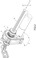
- This disclosure is directed to a driving device 100 as shown in FIGS. 1 to 6 , which is used for driving a swing member O to open or close relative to a main body (not labeled in figures).
- This disclosure is directed to a driving device 100 having clutch function.
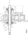
- the first embodiment is shown in FIGS. 1 to 8
- the second embodiment is shown in FIGS. 9 to 17
- the third embodiment is shown in FIGS. 18 to 26 .
- the main body may be a transportation carrier.
- the swing member O may be a door installed on the transportation carrier, for example.
- this application should not be limited to this.
- a driving device 100 has a power transmission assembly 1, a clutch assembly 2a, a screw assembly 3 and a driving power source 6.
- the driving device 100 of this disclosure may be arranged on the main body mentioned above (not shown in figures) and alternatively may be arranged on the swing member O.
- the driving device 100 is provided on the swing member O in this embodiment, for example.
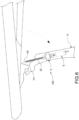
- the swing member O according to this embodiment is connected to the main body through a plurality of conventional hinges (not shown in the figures), and a rotating shaft (not shown in the figure) of the conventional hinge is defined with a first axis H1 as shown in Figures 1 and 6 , the swing member O is rotatable relative to the main body about the first axis H1.
- the main body is provided with a conventional pivotal member, the pivotal member has a pivotal shaft, and the pivotal shaft is defined with a second axis H2 as shown in Figures 1 and 6 .
- the power transmission assembly 1 is driven by the driving power source 6 and capable of transmitting power from the driving power source 6 to the screw assembly 3. It should be noted that, in this application, it is not limited how to drive the power transmission assembly 1 and how to transmit, it may be performed by an approach as shown the figures or others.
- the screw assembly 3 has a nut 31a and a screw rod 32 screwed with each other, and the screw rod 32 in an initial status as shown in FIG. 2 is defined with a longitudinal direction D1 and a radial direction D2, and the longitudinal direction D1 is parallel to the screw rod 32.
- the nut 31a is indirectly driven to rotate by the driving power source 6, so that the screw rod 32 can be extended or retracted along the longitudinal direction D1 relative to the nut 31a; the screw rod 32 has an end connected to the conventional pivotal shaft of the main body mentioned above (this pivotal shaft is defined with a second axis H2).
- the first axis H1 and the second axis H2 mentioned above are disposed at different positions, namely not a co-axial arrangement, the screw rod 32 may be driven by power to extend or retract through this pivotal shaft, so that a moment about the first axis H1 will be generated, and the swing member O will be opened or closed by this moment.
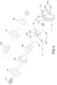
- the nut 31a is not limited in this disclosure, it may be a thick ring (not shown in the figures) commonly used for screwing a bolt or an elongated tube as shown in FIG 3 , for example.
- the clutch assembly 2a having function of connecting and releasing is arranged between the power transmission assembly 1 and the screw assembly 3 as shown in FIG. 4 , so that the nut 31a can be operated by the clutch assembly 2a to connect to or release the power transmission assembly 1 along the radial direction D2.
- the clutch assembly 2a is defined with a connected status and a released status, the clutch assembly 2a is at the connected status when the nut 31a is connected to the power transmission assembly 1 so that the power transmission assembly 1 can transmit power through the nut 31a to move the screw rod 32 along the longitudinal direction D 1; on the contrary, clutch assembly 2a is at the released status when the nut 31a releases the power transmission assembly 1 so that the power transmission assembly 1 cannot transmit power through the nut 31a.
- the clutch assembly 2a may be any component with engaging and disengaging functions and should not be limited in this disclosure, in this embodiment, an example is illustrated in this paragraph.
- the clutch assembly 2a has a first addendum and dedendum structure 21a and a second addendum and dedendum structure 22a capable of engaging with each other.
- the first addendum and dedendum structure 21a is annually disposed on an external periphery of the nut 31a
- the second addendum and dedendum structure 22a are annually disposed on an internal edge in the power transmission assembly 1 of a hollow shape
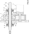
- the first addendum and dedendum structure 21a is engaged with the second addendum and dedendum structure 22a as shown in FIGS. 4 and 5 . According to FIGS.
- the nut 31a is engaged with the power transmission assembly 1 when the first addendum and dedendum structure 21a and the second addendum and dedendum structure 22a are mutually interfered with each other in the radial direction D2 or overlap in the radial direction D2.
- the first addendum and dedendum structure 21a mentioned above has a plurality of first tooth dedendums 211 and a plurality of first tooth addendums 213, the first tooth addendums 213 are disposed at interval and protrudes from the outer periphery of the nut 31a along the radial direction D2, each of the first tooth dedendums 211 is disposed between two of the first tooth addendum 213 which are adjacent to each other;
- the second addendum and dedendum structure 22a has a plurality of second tooth dedendums 221 and a plurality of second tooth addendums 223 arranged on the internal edge of the power transmission assembly 1, the second tooth addendums 223 are extended into the first tooth dedendums 211 respectively along the radial direction D2, the first tooth addendums 213 are extended into the second tooth dedendums 221 respectively along the radial direction D2.
- the tooth addendums are extended into the first tooth dedendums
- the clutch assembly 2a has a first elastic member 24a and a second elastic member 25a used for returning the first addendum and dedendum structure 21a and the second addendum and dedendum structure 22a deviated from each other to the connected status.
- the first elastic member 24a and the second elastic member 25a are respectively disposed at two sides of the nut 31a, so that the nut 31a can be driven by elastic forces caused by the first elastic member 24a and the second elastic member 25a to move along the longitudinal direction D1 and engaged with the power transmission assembly 1 along the radial direction D2 through the clutch assembly 2a.
- the clutch assembly 2a further has a first bearing 26 and a second bearing 27, and the nut 31a has a nut body 310, a first extending segment 311 and a second extending segment 312.
- the nut body 310 can engage or release the power transmission assembly 1 along the radial direction, the first extending segment 311 and the second extending segment 312 are respectively extended from the nut body 310.
- the first bearing 26 and the second bearing 27 are respectively arranged at the first extending segment 311 and the second extending segment 312.
- the first elastic member 24a sleeves the first extending segment 311, and the second elastic member 25a sleeves the second extending segment 312, so that one end of the first elastic member 24a abuts against one side of the first bearing 26, and one end of the second elastic member 25a abuts against one side of the second bearing 27.
- An other end of the first elastic member 24a and an other end of the second elastic member 25a respectively abut against positions which are not limited in this disclosure but illustrated as FIGS. 5 and 7 in this embodiment, for example.
- the other end of the first elastic member 24a and the other end of the second elastic member 25a abut against two sides of an addendum and dedendum combination (namely a combination of the first addendum and dedendum structure 21a and the second addendum and dedendum structure 22a).
- an addendum and dedendum combination namely a combination of the first addendum and dedendum structure 21a and the second addendum and dedendum structure 22a.
- first elastic member 24a and the second elastic member 25a may be long cylinder springs as shown in FIG 3 , short cylinder springs (a first elastic member 24b and a second member 25b belonging to the wave spring as shown in Figure 10 ) or any other springs which are capable of recovery, but should not be limited to the embodiment.
- the driving device 100 has a clutch assembly 2a
- the swing member O can be driven to open or close by the power from the driving power source 6 when the clutch assembly 2a is at the connected status
- the nut 31a is disconnected from the power from the driving power source 6 when the clutch assembly 2a is at the released status (the power transmission assembly 1 is meanwhile driven by the driving power source 6 to idle, and the nut 31a cannot be driven by the power transmission assembly 1 and stops rotation).
- an external force (such as manual force) may be directly applied to the swing member O when the swing member O at any status (e.g. completely opened, completely closed, located at one location between the completely opened and completely closed positions or during a power-driven operation of opening of closing).
- the swing member O can be stopped during a power-driven operation of opening of closing, but an operation the external force should not be limited to the embodiment in this disclosure.
- the power transmission assembly 1 or other mechanical parts in the driving power source 6 cannot be reversed by the external force because the power from the driving power source 6 is disconnected from the nut 31a, so as to avoid from mechanical damage.
- the clutch assembly 2a at the released status can be returned to the connected status by the elastic forces caused by the first elastic member 24a and the second elastic member 25a when the external force is not present. Accordingly, the nut 31a can engage to or release the power transmission assembly 1 when the screw assembly 3 is moved along the longitudinal direction D1 relative to the power transmission assembly 1 (to extend or retract).
- the swing member O will be moved with the power transmission assembly 1 relative to the screw assembly 3 to switch the clutch assembly 2a to the released status when an user touch the swing member O, so as to disconnect the nut 31a from the power from the driving power source 6, thereby preventing the driving device 100 from damage and allowing an manual operation to interrupt a power-driven operation.
- the first elastic member 24a and the second elastic member 25a provide elastic forces sufficient for resist the gravity applied on the swing member O, so as to maintain the clutch assembly 2a at the connected status.
- the driving device 100 in order to allow the screw assembly 3 to swing, the driving device 100 according to this disclosure further has a housing 5, the housing 5 is arranged on the swing member O and the housing 5 has a limiting portion 50, the power transmission assembly 1 is arranged on the limiting portion 50 and configured to be rotatable.
- the power transmission assembly 1 may be a sphere 11, the power transmission assembly 1 is correspondingly arranged in the limiting portion 50, the driving power source 6 is also arranged in the housing 5.
- the housing 5 further has a first bushing 51 and a second bushing 52 which are both arranged on the limiting portion 50, the power transmission assembly 1 is arranged between the first bushing 51 and the second bushing 52 to allow the power transmission assembly 1 to be rotated relative to the housing 5.
- the power transmission assembly 1 is rotated with the angular variation of the screw rod 32 mentioned above.
- the screw assembly 3 is allowed to swing, so as to avoid an angular variation between the screw rod 32 and the first axis H1 mentioned above and occurring in an opening operation or a closing operation of the swing member O, and also prevent the swing member O from sagging relative to the main body mentioned above.
- the power transmission assembly 1 has a ring gear 12 and the sphere 11 mentioned above, the ring gear 12 is configured to surround an external periphery of the sphere 11, the power transmission assembly 1 is meshed with the driving power source 6 via the ring gear 12, so that the power transmission assembly 1 can be driven by the driving power source 6.
- the ring gear 12 is a ring disposed with a plurality of driven teeth 121 of oval shapes, so that the driven teeth 121 is meshed with a driving gear 62 of the driving power source 6 and allowed to swing when the power transmission assembly 1 is rotated.
- the sphere 11 and the ring gear 12 may be configured as one piece or assembled to each other, but it should not be limited in this disclosure.
- each of the driven teeth 121 are disposed on the external periphery of the sphere 11 along the longitudinal direction D1, and each of the driven teeth 121 has an outer edge 1211 away from the external periphery of the sphere 11, the outer edge 1211 is of an arc shape; each of the driven teeth 121 has two end portion 1215 disposed on the longitudinal direction D1, each of the end portion 1215 is of a shape converged from the external periphery of the sphere 11 along a direction away from the external periphery of the sphere 11.
- the sphere 11 as shown in FIG. 3-1 has a first hemispherical structure 111 and a second hemispherical structure 112, the first hemispherical structure 111 and the second hemispherical structure 112 are respectively arranged at two sides of the ring gear 12, and the first hemispherical structure 111 and the second hemispherical structure 112 are respectively contacted with the first bushing 51 and the second bushing 52 as shown in FIG. 5 , so that the power transmission assembly 1 can be held at a position in the housing 5 and configured to be rotatable.
- first extending segment 311 and the second extending segment 312 of the nut 31a are respectively inserted in a first stopping ring 35 and a second stopping ring 36.
- the first stopping ring 35 is contacted with only an outer ring of the first bearing 26 and the second stopping ring 36 is contacted with only an outer ring of the second bearing 27 respectively.
- An inner ring of the first bearing 26 is contacted with one end of the first elastic member 24a and an inner ring of the second bearing 27 is contacted with one end of the second elastic member 25a, so that one of the inner ring and the outer ring of the first bearing 26 is rotatable relative to another, and one of the inner ring and outer ring of the second bearing 27 is rotatable relative to another.
- the driving power source 6 may be any component capable of power driving and should not be limited to the embodiment in this application. According to an example illustrated in this embodiment, the driving power source 6 has a driving body 61 and a driving gear 62 as shown in Figure 2 .
- the driving gear 62 is driven to rotate by the driving body 61.
- the driving gear 62 is meshed with the ring gear 12.
- the power transmission assembly 1 is driven to rotate by the driving body 61 through the driving gear 62.
- the driving body 61 may be a motor.
- the second embodiment of the driving device 100 of this disclosure is substantially the same as the first embodiment, and only different at the clutch assembly 2b and the nut 31b.
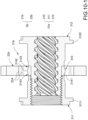
- the clutch assembly 2b has an interactive structure 21b, an engaging structure 224 and a plurality of rollers 28, and the clutch assembly 2b further has a cage 29b in this embodiment.
- the engaging structure 224 is annually disposed on the internal edge of the power transmission assembly 1 of a hollow shape;
- the interactive structure 21b is annually disposed on the external periphery of the nut 31b and fixed with the nut 31b,
- the interactive structure 21b has a convex portion 2142 and two concave portions 2143 dent relative to the convex portion 2142, the convex portion 2142 and the two concave portions 2143 are disposed side by side along the longitudinal direction D1;
- the plurality of rollers 28 are arranged between the engaging structure 224 and the interactive structure 21b.
- the nut 31b has an outer peripheral surface 2141 on the external periphery
- the interactive structure 21b is configured to surround the outer peripheral surface 2141 of the nut 31b
- the convex portion 2142 protrudes from one portion of the outer peripheral surface 2141 along the radial direction D2 as shown in FIG. 10-1
- the concave portion 2143 is correspondingly disposed between the convex portion 2142 and remained portions of the outer peripheral surface 2141.
- the interactive structure 21b may be formed with the nut body 310 as one piece or assembled with the nut body 310.
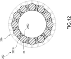
- the cage 29b has a plurality of accommodating holes 292 disposed along the radial direction D2, the rollers 28 are accommodated in the accommodating holes 292 respectively and configured to be movable.
- the cage 29b is arranged in the sphere 11 of the power transmission assembly 1, and the engaging structure 224 is configured to surround the rollers 28 along the radial direction D2.
- Each of the accommodating holes 292 has an opening 2921b and a convergent opening 2922 disposed on the radial direction D2, each of the rollers 28 has one portion exposed toward the engaging structure 224 through the opening 2921b and an other portion exposed toward the interactive structure 21b through the convergent opening 2922, so that the portion and the other potion in each of the rollers 28 are applied to the engaging structure 224 and the interactive structure 21b respectively.
- the first extending segment 311of the nut 31b has a first stopping portion 3111
- the second extending segment 312 of the nut 31b has a second stopping portion 3122
- the first elastic member 24b sleeves the first extending segment 311
- the second elastic member 25b sleeves the second extending segment 312, so that the first elastic member 24b is disposed between the first stopping portion 3111 and one side of the cage 29b for elastically supporting, and the second elastic member 25b is disposed between the second stopping portion 3122 and another side of the cage 29b for elastically supporting.
- the cage 29b may be a single-piece structure (not shown in the figures) or a combination structure as shown in FIG. 11 which has a first cage member 2901 and a second cage member 2902 which can be combined with each other.
- a surrounding groove 291 is defined on a combination of the first cage member 2901 and the second cage member 2902.
- the clutch assembly 2b further has an engaging ring 22b, the engaging ring 22b is arranged on the sphere 11 and provided with an engaging structure 224, the cage 29b is arranged between the power transmission assembly 1 and the nut 31b and defined with a surrounding groove 291 as shown in FIG. 10 , the surrounding groove 291 is communicated with the openings 2921b respectively, the engaging ring 22b has one portion extended into the surrounding groove 291, and the engaging structure 224 is disposed to face the openings 2921b respectively.
- the engaging structure 224 may be any component capable of engaging and should not be limited to the embodiment in this disclosure.
- the engaging structure 224 has a shape which allows the rollers 28 to engage the engaging structure 224 and the interactive structure 21b; the engaging ring 22b may be fixed with the power transmission assembly 1 by any approach capable of fixing and should not be limited to the embodiment in this disclosure.
- An example as shown in FIGS. 13 and 15 is illustrated in following paragraph: the engaging ring 22b has at least a latching structure 225 protruding along the radial direction D2.
- the ring gear 12 has at least a counterpart latching structure 122, the counterpart latching structure 122 is latched by the latching structure 225 so as to fix the engaging ring 22b with the ring gear 12.
- the driving power source 6 as shown in FIG. 14 further has a worm gear 63.
- the worm gear 63 and the driving gear 62 are fixed with each other and configured to be coaxial.
- the driving body 61 has a driving shaft 611.
- a spiral thread 612 protrudes from the outer periphery of the driving shaft 611, and the spiral thread 612 meshes with the worm gear 63. In this way, the tooth profile design of the spiral thread 612 and the worm gear 63 can prevented the spiral thread 612 from reverse driving.
- the nut 31a can be driven to rotate by the transmission assembly power transmission assembly 1 when the transmission assembly power transmission assembly 1 is driven to rotate by the driving power source 6 so as to move the screw rod 32 along the longitudinal direction D1 and further drive the swing member O to open or close.
- the rollers 28 follows the cage 29b to move along the longitudinal direction D1.
- the driving device 100 of this disclosure has a clutch assembly 2b.
- the clutch assembly 2b allows the swing member O to be driven to open or close by a driving power from the driving source 6 when the clutch assembly 2b is in the connected status; the driving power from the driving power source 6 is disconnected from the nut 31b when the clutch assembly 2b is in the released status.
- an external force (such as manual force) may be directly applied to the swing member O when the swing member O is at any status (e.g. completely opened, completely closed, located at one location between the completely opened and completely closed positions or during a power-driven operation of opening of closing).
- the swing member O can be stopped during a power-driven operation of opening of closing, but an operation of the external force should not be limited to the embodiment in this disclosure.
- the external force the power transmission assembly 1 or other mechanism components in the driving power source 6 cannot be reversely driven, because the driving power from the driving power source 6 is disconnected from the nut 31b so as to prevent the driving device 100 from damage caused by this, and a power-driven operation is allowed to be interrupted by a manual operation in any status.
- the clutch assembly 2b can be returned to the connected status from the released status by elastic recovery forces caused by the first elastic member 24b and the second elastic member 25b when the external force applied thereon is canceled.
- the nut 31a can engage to or release the power transmission assembly 1 when the screw assembly 3 is moved along the longitudinal direction D1 relative to the power transmission assembly 1 (to extend or retract).
- the second embodiment of the driving device 100 of this disclosure performs all the effects the same as the first embodiment.
- the housing 5 and the power transmission assembly 1 may be driven by gravity to move with the cage 29b and the engaging structure 224 along the longitudinal direction D1 if the swing member O is in the opened position when the transportation carrier is parked on a slope as mentioned above, because the swing member O is affected by gravity (a type of external force).
- the convex portion 2142 of the interactive structure 21b has a specific width cooperated with strokes of the first elastic member 24b and the second elastic member 25b, so that the rollers 28 can be held to engage between the engaging structure 224 and the convex portion 2142 when the roller 28 are not completely separated from the convex portion 2142.
- the first elastic member 24b is pressed by the cage 29b pushes, and the first elastic member 24b will be driven to press the first stopping portion 3111 of the nut 31b, so that the nut 31b is driven to further rotate relative to the screw rod 32.
- This rotation of the cage 29b mentioned above is driven through two ends of the first elastic member 24b.
- the rollers 28 are held by the cage 29b to engage between the engaging structure 224 and the convex portion 2142.
- the gravity applied on the swing member O is not enough to drive the nut 31b to rotate the power transmission assembly 1 and the driving power source 6, so that the swing member O can be held at an opened position.
- the driving power source 6 mentioned above further has a worm gear 63 so that the tooth profile mentioned above prevents the nut 3 1b from driving the power transmission assembly 1 and the driving power source 6 to rotate.
- FIGS. 18 to 26 As shown in, it is the driving device 100 according to the third embodiment of the present application is shown in FIGS. 18 to 26 .
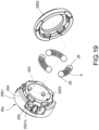
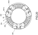
- the third embodiment is substantially the same as the second embodiment and different at that the engaging ring 22c and the cage 29c are, and the clutch assembly 2b further has a plurality of auxiliary elastic members S.
- the auxiliary elastic member S are arranged in the cage 29c respectively, and each of auxiliary elastic member S is disposed between two of the rollers 28 adjacent to each other for elastically supporting, namely that the rolls 28 may be limited by the auxiliary elastic members S.
- the engaging structure 224 has a plurality of engaging blocks 2241correspondingly configured to surround the internal edge of the power transmission assembly 1, each of the engaging blocks 2241 has two engaging protrusions 2242 and a releasing recess 2243 dent relative to the engaging protrusions 2242, and the releasing recess 2243 is disposed between the two engaging protrusions 2242.
- Each of the roller 28 is engaged between the convex portion 2142 and the engaging protrusions 2242 of one of the engaging blocks 2241.
- the cage 29c has a plurality of accommodating holes 292 and a plurality of through ways 293, each of the through ways 293 is communicated between two of the accommodating holes 292 adj acent to each other, and the auxiliary elastic members S are respectively accommodated in the through ways 293 between two of the rollers 28 adjacent to each other for elastically supporting.
- Each of the accommodating hole 292 has a notch 2921c and a convergent opening 2922, each of the accommodating hole 292 is communicated to the through way 293 through the notch 2921c thereof.
- each of the rollers 28 has one portion which may contact the engaging structure 224 through the notch 2921c and another portion exposed toward the interactive structure 21bthrough the convergent opening 2922 respectively.
- the engaging ring 22c and the cage 29c are fixed with each other.
- each roller 28 when each roller 28 is correspondingly clamped between the engaging protrusion 2242 and the convex portion 2142, the nut 31c is engaged with the power transmission assembly 1.
- the swing member O when the swing member O is driven by an external force to move the power transmission assembly 1 and the cage 29c and the engaging structure 224 along.
- the longitudinal direction D1 each roller 28 is moved along the longitudinal direction D1 with the cage 29c from the convex portion 2142 to a position between the releasing recess 2243 and the concave portion 2143, so that each roller 28 will not be clamped by the engaging structure 224, and then the power transmission assembly 1 is separated from the nut 31c.
- the driving device 100 of this disclosure has a clutch assembly 2b.
- the clutch assembly 2b allows the swing member O to be driven to open or close by a driving power from the driving source 6 when the clutch assembly 2b is in the connected status; the driving power from the driving power source 6 is disconnected from the nut 31c when the clutch assembly 2b is in the released status.
- an external force (such as manual force) may be directly applied to the swing member O when the swing member O at any status (e.g. completely opened, completely closed, located at one location between the completely opened and completely closed positions or during a power-driven operation of opening of closing).
- the swing member O can be stopped during a power-driven operation of opening of closing, but an operation the external force should not be limited to the embodiment in this disclosure.
- the external force the power transmission assembly 1 or other mechanism components in the driving power source 6 cannot be reversely driven, because the driving power from the driving power source 6 is disconnected from the nut 3 1b so as to prevent the driving device 100 from damage caused by this, and a power-driven operation is allowed to be interrupted by a manual operation in any status.
- the clutch assembly 2b can be returned to the connected status from the released status by elastic recovery forces caused by the first elastic member 24b and the second elastic member 25b when the external force applied thereon is canceled.
- the nut 31a can engage to or release the power transmission assembly 1 when the screw assembly 3 is moved along the longitudinal direction D1 relative to the power transmission assembly 1(to extend or retract).
- the third embodiment of the driving device 100 of this disclosure performs all the effects the same as the second embodiment.
- auxiliary elastic members S are accommodated in the through ways 293 respectively and each of the auxiliary elastic members is disposed between two of the rollers 28 adj acent to each other for elastically supporting, thereby stably holding the two rollers 28 adjacent to each other between the engaging protrusion 2242 and the convex portion 2142, namely that, as an example shown in FIG. 24 , each rollers 28 is driven by the elastic forces caused by the auxiliary elastic members S to directly engage the engaging protrusion 2242 when the cage 29c is moved by the elastic force caused by the first elastic members 24b to a position corresponding to the engaging protrusions 2242.
- the driving device 100 of this disclosure can achieve the predetermined purpose and effect to solve the issues of related art, and a patent application is therefore filed.
Landscapes
- Engineering & Computer Science (AREA)
- General Engineering & Computer Science (AREA)
- Mechanical Engineering (AREA)
- Transmission Devices (AREA)
Applications Claiming Priority (1)
| Application Number | Priority Date | Filing Date | Title |
|---|---|---|---|
| US202363457795P | 2023-04-06 | 2023-04-06 |
Publications (1)
| Publication Number | Publication Date |
|---|---|
| EP4442945A1 true EP4442945A1 (de) | 2024-10-09 |
Family
ID=90719051
Family Applications (1)
| Application Number | Title | Priority Date | Filing Date |
|---|---|---|---|
| EP24168592.4A Pending EP4442945A1 (de) | 2023-04-06 | 2024-04-04 | Antriebsvorrichtung |
Country Status (5)
| Country | Link |
|---|---|
| US (1) | US12553274B2 (de) |
| EP (1) | EP4442945A1 (de) |
| JP (1) | JP7826360B2 (de) |
| CN (1) | CN118774526A (de) |
| TW (1) | TWI891293B (de) |
Cited By (1)
| Publication number | Priority date | Publication date | Assignee | Title |
|---|---|---|---|---|
| CN120251676A (zh) * | 2025-06-09 | 2025-07-04 | 云南新天力机械制造股份有限公司 | 一种摩托车多挡变速驱动结构 |
Citations (6)
| Publication number | Priority date | Publication date | Assignee | Title |
|---|---|---|---|---|
| US3202414A (en) * | 1962-01-15 | 1965-08-24 | Gen Motors Corp | Vehicle door actuator |
| US6237433B1 (en) * | 1998-05-12 | 2001-05-29 | Trw Systemes Aeronauliques Civils | Electromechanical actuator of the type having a screw-and-nut system |
| US10655378B2 (en) * | 2017-02-07 | 2020-05-19 | Magna Closures Inc. | Power side door actuator with rotating drive nut |
| DE102019100827A1 (de) * | 2019-01-14 | 2020-07-16 | Brose Fahrzeugteile Se & Co. Kommanditgesellschaft, Bamberg | Antriebsanordnung zur motorischen Verstellung einer Klappe eines Kraftfahrzeugs |
| CN112443230A (zh) * | 2019-08-28 | 2021-03-05 | 朱丹 | 汽车自动侧门开闭系统 |
| EP3828371A1 (de) * | 2019-11-26 | 2021-06-02 | Edscha Engineering GmbH | Antriebsvorrichtung |
Family Cites Families (6)
| Publication number | Priority date | Publication date | Assignee | Title |
|---|---|---|---|---|
| US5086900A (en) * | 1987-03-31 | 1992-02-11 | Asmo Co., Ltd. | Power converting mechanism |
| GB2287277B (en) * | 1994-03-10 | 1997-11-12 | Rockwell Body & Chassis Syst | Vehicle lock actuator transmission |
| TWI326517B (en) * | 2006-12-08 | 2010-06-21 | Moteck Electric Copr | Linear actuating apparatus and manufacturing method of the same |
| DE102015110089A1 (de) * | 2014-06-27 | 2015-12-31 | Magna Closures Inc. | Elektromechanische Strebe mit integrierter Flexkupplung und Schlupfvorrichtung und zugehörige Kupplungs-/Kopplungs-Anordnung |
| DE102018212959A1 (de) * | 2018-08-02 | 2020-02-06 | Stabilus Gmbh | Schwenkbare Spindelmutter |
| WO2021019670A1 (ja) | 2019-07-30 | 2021-02-04 | 日鍛バルブ株式会社 | 電動パワーステアリング装置 |
-
2024
- 2024-03-20 TW TW113110382A patent/TWI891293B/zh active
- 2024-04-01 CN CN202410386071.3A patent/CN118774526A/zh active Pending
- 2024-04-03 US US18/625,411 patent/US12553274B2/en active Active
- 2024-04-03 JP JP2024059995A patent/JP7826360B2/ja active Active
- 2024-04-04 EP EP24168592.4A patent/EP4442945A1/de active Pending
Patent Citations (6)
| Publication number | Priority date | Publication date | Assignee | Title |
|---|---|---|---|---|
| US3202414A (en) * | 1962-01-15 | 1965-08-24 | Gen Motors Corp | Vehicle door actuator |
| US6237433B1 (en) * | 1998-05-12 | 2001-05-29 | Trw Systemes Aeronauliques Civils | Electromechanical actuator of the type having a screw-and-nut system |
| US10655378B2 (en) * | 2017-02-07 | 2020-05-19 | Magna Closures Inc. | Power side door actuator with rotating drive nut |
| DE102019100827A1 (de) * | 2019-01-14 | 2020-07-16 | Brose Fahrzeugteile Se & Co. Kommanditgesellschaft, Bamberg | Antriebsanordnung zur motorischen Verstellung einer Klappe eines Kraftfahrzeugs |
| CN112443230A (zh) * | 2019-08-28 | 2021-03-05 | 朱丹 | 汽车自动侧门开闭系统 |
| EP3828371A1 (de) * | 2019-11-26 | 2021-06-02 | Edscha Engineering GmbH | Antriebsvorrichtung |
Cited By (1)
| Publication number | Priority date | Publication date | Assignee | Title |
|---|---|---|---|---|
| CN120251676A (zh) * | 2025-06-09 | 2025-07-04 | 云南新天力机械制造股份有限公司 | 一种摩托车多挡变速驱动结构 |
Also Published As
| Publication number | Publication date |
|---|---|
| TWI891293B (zh) | 2025-07-21 |
| CN118774526A (zh) | 2024-10-15 |
| US12553274B2 (en) | 2026-02-17 |
| JP7826360B2 (ja) | 2026-03-09 |
| TW202441060A (zh) | 2024-10-16 |
| US20240337147A1 (en) | 2024-10-10 |
| JP2024149424A (ja) | 2024-10-18 |
Similar Documents
| Publication | Publication Date | Title |
|---|---|---|
| US11187008B2 (en) | Clutch engagement assembly of door lock and driving device thereof | |
| US12553274B2 (en) | Driving device | |
| US9976332B2 (en) | Electromechanical strut with integrated flex coupling and slip device and clutch/coupling assembly therefor | |
| US20150040704A1 (en) | Synchronous movement device applied to dual-shaft system | |
| TWI673142B (zh) | 棘輪設備及其組裝方法 | |
| US5938251A (en) | Powered closing device for a vehicle door with a safety mechanism | |
| CN112041523B (zh) | 把手布置及其用途 | |
| JP2008303699A (ja) | スウィング・ボルトを備えた鍵及びそのアクチュエータ・アセンブリ | |
| US9702179B2 (en) | Closer device and vehicle door locking device | |
| CN109695396B (zh) | 离合自动开门装置及冰箱 | |
| US7694390B2 (en) | Hinge mechanism for foldable electronic device | |
| CN114837499B (zh) | 具有电动开启、吸合支链的自适应多功能汽车侧门锁 | |
| US12560000B2 (en) | Motorized locking device for opening/shutting unit | |
| CN100417783C (zh) | 用于窗户、门的附件的传动机构及采用该传动机构的附件 | |
| JP6199300B2 (ja) | ケーブル装置 | |
| CN111734931A (zh) | 用于摄影器材的电控滑动装置及其锁定组件 | |
| CN216076709U (zh) | 用于门锁的驱动机构、门锁 | |
| CN216406501U (zh) | 闭门装置及具有其的冰箱 | |
| CN112825379B (zh) | 电池组件 | |
| EP3667003B1 (de) | Verriegelungsmechanismus | |
| KR20220076645A (ko) | 차량의 테일게이트 개폐장치 | |
| CN115822387B (zh) | 一种电子门锁及其翻转斜舌组件 | |
| JP7738892B2 (ja) | サムターン装置 | |
| KR20220053153A (ko) | 차량의 테일게이트 개폐장치 | |
| CN224078904U (zh) | 一种基于凸轮连杆的执行机构 |
Legal Events
| Date | Code | Title | Description |
|---|---|---|---|
| PUAI | Public reference made under article 153(3) epc to a published international application that has entered the european phase |
Free format text: ORIGINAL CODE: 0009012 |
|
| STAA | Information on the status of an ep patent application or granted ep patent |
Free format text: STATUS: THE APPLICATION HAS BEEN PUBLISHED |
|
| AK | Designated contracting states |
Kind code of ref document: A1 Designated state(s): AL AT BE BG CH CY CZ DE DK EE ES FI FR GB GR HR HU IE IS IT LI LT LU LV MC ME MK MT NL NO PL PT RO RS SE SI SK SM TR |
|
| STAA | Information on the status of an ep patent application or granted ep patent |
Free format text: STATUS: REQUEST FOR EXAMINATION WAS MADE |
|
| 17P | Request for examination filed |
Effective date: 20250129 |
|
| STAA | Information on the status of an ep patent application or granted ep patent |
Free format text: STATUS: EXAMINATION IS IN PROGRESS |
|
| 17Q | First examination report despatched |
Effective date: 20250627 |
|
| GRAP | Despatch of communication of intention to grant a patent |
Free format text: ORIGINAL CODE: EPIDOSNIGR1 |
|
| STAA | Information on the status of an ep patent application or granted ep patent |
Free format text: STATUS: GRANT OF PATENT IS INTENDED |