EP4442915A2 - Modulare toilettenplatte - Google Patents
Modulare toilettenplatte Download PDFInfo
- Publication number
- EP4442915A2 EP4442915A2 EP24163374.2A EP24163374A EP4442915A2 EP 4442915 A2 EP4442915 A2 EP 4442915A2 EP 24163374 A EP24163374 A EP 24163374A EP 4442915 A2 EP4442915 A2 EP 4442915A2
- Authority
- EP
- European Patent Office
- Prior art keywords
- toilet
- lock
- lid
- controller
- input
- Prior art date
- Legal status (The legal status is an assumption and is not a legal conclusion. Google has not performed a legal analysis and makes no representation as to the accuracy of the status listed.)
- Pending
Links
Images








Classifications
-
- E—FIXED CONSTRUCTIONS
- E03—WATER SUPPLY; SEWERAGE
- E03D—WATER-CLOSETS OR URINALS WITH FLUSHING DEVICES; FLUSHING VALVES THEREFOR
- E03D11/00—Other component parts of water-closets, e.g. noise-reducing means in the flushing system, flushing pipes mounted in the bowl, seals for the bowl outlet, devices preventing overflow of the bowl contents; devices forming a water seal in the bowl after flushing, devices eliminating obstructions in the bowl outlet or preventing backflow of water and excrements from the waterpipe
- E03D11/02—Water-closet bowls ; Bowls with a double odour seal optionally with provisions for a good siphonic action; siphons as part of the bowl
-
- E—FIXED CONSTRUCTIONS
- E03—WATER SUPPLY; SEWERAGE
- E03D—WATER-CLOSETS OR URINALS WITH FLUSHING DEVICES; FLUSHING VALVES THEREFOR
- E03D11/00—Other component parts of water-closets, e.g. noise-reducing means in the flushing system, flushing pipes mounted in the bowl, seals for the bowl outlet, devices preventing overflow of the bowl contents; devices forming a water seal in the bowl after flushing, devices eliminating obstructions in the bowl outlet or preventing backflow of water and excrements from the waterpipe
- E03D11/13—Parts or details of bowls; Special adaptations of pipe joints or couplings for use with bowls, e.g. provisions in bowl construction preventing backflow of waste-water from the bowl in the flushing pipe or cistern, provisions for a secondary flushing, for noise-reducing
-
- A—HUMAN NECESSITIES
- A47—FURNITURE; DOMESTIC ARTICLES OR APPLIANCES; COFFEE MILLS; SPICE MILLS; SUCTION CLEANERS IN GENERAL
- A47K—SANITARY EQUIPMENT; ACCESSORIES THEREFOR, e.g. TOILET ACCESSORIES
- A47K13/00—Seats or covers for all kinds of closets
- A47K13/24—Parts or details not covered in, or of interest apart from, groups A47K13/02 - A47K13/22
- A47K13/242—Devices for locking the cover in the closed position
-
- E—FIXED CONSTRUCTIONS
- E03—WATER SUPPLY; SEWERAGE
- E03D—WATER-CLOSETS OR URINALS WITH FLUSHING DEVICES; FLUSHING VALVES THEREFOR
- E03D3/00—Flushing devices operated by pressure of the water supply system flushing valves not connected to the water-supply main, also if air is blown in the water seal for a quick flushing
-
- E—FIXED CONSTRUCTIONS
- E03—WATER SUPPLY; SEWERAGE
- E03D—WATER-CLOSETS OR URINALS WITH FLUSHING DEVICES; FLUSHING VALVES THEREFOR
- E03D5/00—Special constructions of flushing devices, e.g. closed flushing system
- E03D5/02—Special constructions of flushing devices, e.g. closed flushing system operated mechanically or hydraulically (or pneumatically) also details such as push buttons, levers and pull-card therefor
- E03D5/08—Special constructions of flushing devices, e.g. closed flushing system operated mechanically or hydraulically (or pneumatically) also details such as push buttons, levers and pull-card therefor directly by the foot combined with devices for opening or closing shutters in the bowl outlet and/or with devices for raising or lowering seat and cover and/or for swiveling the bowl
-
- E—FIXED CONSTRUCTIONS
- E03—WATER SUPPLY; SEWERAGE
- E03D—WATER-CLOSETS OR URINALS WITH FLUSHING DEVICES; FLUSHING VALVES THEREFOR
- E03D5/00—Special constructions of flushing devices, e.g. closed flushing system
- E03D5/02—Special constructions of flushing devices, e.g. closed flushing system operated mechanically or hydraulically (or pneumatically) also details such as push buttons, levers and pull-card therefor
- E03D5/09—Special constructions of flushing devices, e.g. closed flushing system operated mechanically or hydraulically (or pneumatically) also details such as push buttons, levers and pull-card therefor directly by the hand
-
- E—FIXED CONSTRUCTIONS
- E03—WATER SUPPLY; SEWERAGE
- E03D—WATER-CLOSETS OR URINALS WITH FLUSHING DEVICES; FLUSHING VALVES THEREFOR
- E03D5/00—Special constructions of flushing devices, e.g. closed flushing system
- E03D5/10—Special constructions of flushing devices, e.g. closed flushing system operated electrically, e.g. by a photo-cell; also combined with devices for opening or closing shutters in the bowl outlet and/or with devices for raising/or lowering seat and cover and/or for swiveling the bowl
- E03D5/105—Special constructions of flushing devices, e.g. closed flushing system operated electrically, e.g. by a photo-cell; also combined with devices for opening or closing shutters in the bowl outlet and/or with devices for raising/or lowering seat and cover and/or for swiveling the bowl touchless, e.g. using sensors
-
- E—FIXED CONSTRUCTIONS
- E03—WATER SUPPLY; SEWERAGE
- E03D—WATER-CLOSETS OR URINALS WITH FLUSHING DEVICES; FLUSHING VALVES THEREFOR
- E03D11/00—Other component parts of water-closets, e.g. noise-reducing means in the flushing system, flushing pipes mounted in the bowl, seals for the bowl outlet, devices preventing overflow of the bowl contents; devices forming a water seal in the bowl after flushing, devices eliminating obstructions in the bowl outlet or preventing backflow of water and excrements from the waterpipe
- E03D11/13—Parts or details of bowls; Special adaptations of pipe joints or couplings for use with bowls, e.g. provisions in bowl construction preventing backflow of waste-water from the bowl in the flushing pipe or cistern, provisions for a secondary flushing, for noise-reducing
- E03D11/135—Supports for bowls
-
- E—FIXED CONSTRUCTIONS
- E03—WATER SUPPLY; SEWERAGE
- E03D—WATER-CLOSETS OR URINALS WITH FLUSHING DEVICES; FLUSHING VALVES THEREFOR
- E03D11/00—Other component parts of water-closets, e.g. noise-reducing means in the flushing system, flushing pipes mounted in the bowl, seals for the bowl outlet, devices preventing overflow of the bowl contents; devices forming a water seal in the bowl after flushing, devices eliminating obstructions in the bowl outlet or preventing backflow of water and excrements from the waterpipe
- E03D11/13—Parts or details of bowls; Special adaptations of pipe joints or couplings for use with bowls, e.g. provisions in bowl construction preventing backflow of waste-water from the bowl in the flushing pipe or cistern, provisions for a secondary flushing, for noise-reducing
- E03D11/14—Means for connecting the bowl to the wall, e.g. to a wall outlet
- E03D11/143—Mounting frames for toilets and urinals
-
- E—FIXED CONSTRUCTIONS
- E03—WATER SUPPLY; SEWERAGE
- E03D—WATER-CLOSETS OR URINALS WITH FLUSHING DEVICES; FLUSHING VALVES THEREFOR
- E03D5/00—Special constructions of flushing devices, e.g. closed flushing system
- E03D5/02—Special constructions of flushing devices, e.g. closed flushing system operated mechanically or hydraulically (or pneumatically) also details such as push buttons, levers and pull-card therefor
- E03D5/04—Special constructions of flushing devices, e.g. closed flushing system operated mechanically or hydraulically (or pneumatically) also details such as push buttons, levers and pull-card therefor directly by the seat or cover combined with devices for opening and closing shutters in the bowl outlet and/or with devices for raising and lowering seat or cover; Raising or lowering seat and/or cover by flushing or by the flushing mechanism
Definitions
- the present disclosure relates generally to toilets. More specifically, the present disclosure relates to a toilet having modular features and/or features that improve manufacturing of the toilet.
- Conventional toilets may be formed nearly entirely from porcelain or other ceramic materials.
- the porcelain may be treated or coated with vitreous china.
- the toilet is fired at a high temperature until it is hardened.
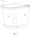
- the toilet 100 includes a cover and seat opening mechanism that allows both a cover 10 and a seat 12 to be easily moved relative to the toilet 100 and to maintain the cleanliness and appearance of the toilet 100.
- Modular panels e.g., front panel 102 and one or more side panels 101
- Various colors, textures, designs, artwork, images, patterns, photographs, or combinations thereof may be added to the modular panels.
- the modular panels may be removed and replaced with other panels with different aesthetics.
- tankless toilets are illustrated.
- the flush is powered by line pressure of the water source (e.g., municipal water line) or an auxiliary pump.
- certain aspects may be applied to a toilet with a tank formed separately from a pedestal and later coupled to the pedestal, or applied to a toilet in which the tank may be integrally formed with the pedestal as a one-piece design.
- the toilet may be a one-piece design, a two-piece design, or have any suitable configuration.
- the toilet disclosed herein may have a wide variety of skirted toilet configurations, and all such configurations are intended to be encompassed herein.
- the following description of various toilet features is therefore intended as illustration only of one possible embodiment, and it should be understood by those reviewing the present description that similar concepts or features may be included in various other embodiments.
- the shapes and configurations of the tank, pedestal, seat assembly, and the internal components may vary from the embodiments shown and described herein, and that the embodiments disclosed herein are not intended as limitations.
- various components of the toilet may be made of vitreous china.
- various components of the toilet may be polymeric and/or over molded or otherwise fixed to the toilet.
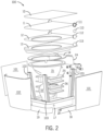
- FIG. 2 is an exploded view of the toilet 100 of FIG. 1 .
- the toilet 100 may include the lid 10, a lid housing 11, the seat 12, a seat housing 13, a rim channel assembly 14, a rim water supply 24, a bowl 15, a trapway 16, a frame (e.g., horizontal frame 17 and vertical frame 103), a front lift plate 19, and a side lift plate 18.
- the bowl 15 may include assembly fixtures or grips 25.
- the trapway 16 may include assembly fixtures or grips 26.
- These components of the toilet 100 may be enclosed by the modular panels including the front panel 102 and the side panel 101. Additional, different, or fewer components may be included. For example, hand rests or assist rails may be installed on the sides of the toilet 100.
- the lid housing 11 may include an aperture 111 to rotatable support the local control 110 (e.g., push button).
- the seat 12 may include a mating cylinder 112 configured to couple to the aperture 111 and the local control 110.
- the local control 110 or push button may be aligned with a rotation axis of the lid housing 10, the seat 12, the lid housing 11 and/or the seat housing 13.
- the push button may be operable to move in a path along a line of the axis of the lid housing 10, the seat 12, the lid housing 11 and/or the seat housing 13.
- FIG. 3 is an example manufacturing setting for the toilet of FIG. 1 .
- a robot 80 may be controlled by a remote user, a stored series of commands or instructions, or data feedback from one or more sensors.
- the sensors may include position sensors, optical sensors, or other sensors to detect the relative location of parts of the toilet 100 and the robot 80 (e.g., robot arm including one or more motors and actuators to move to any position and grip objects with grippers).
- the robot 80 is configured to pick up and assemble the parts of the toilet 100.
- FIG. 4 is a flow chart for an example manufacturing process for the toilet of FIG. 1 . Additional, different, or fewer acts may be included.
- Each of the parts for the toilet 100 may be selected by the robot according to an order or user specification. For example, various colors and designs may be available for the trim (e.g., frame members, panels, etc.) and the robot 80 selects the corresponding parts based on the user selections.
- the robot 80 lowers a toilet engine guide 72 into a manufacturing support 70.
- the manufacturing support 70 includes at least one stand 73 configured to support the toilet engine guide 72.
- the manufacturing support 70 includes at least one guide member 74 that aligns with the frame members 103 when the toilet engine guide 72 rests on the stand 73.
- the robot 80 aligns the frame members 103 with the manufacturing support 70.
- the frame members 103 may be rotatably connected to the toilet engine guide 72 such that the frame members 103 rotate with the frame members 103 contact the manufacturing support 70.
- each of the frame members 103 contacts one of the guide members 74.
- the guide members 74 each include an angled surface having a slope equivalent to the desired angle for the guide members 74 to construct the toilet 100. As the toilet engine guide 72 and frame members 103 are lowered in to the manufacturing support 70, the frame members 103 contact the guide members 74, and in response, rotate to become aligned with the guide members 74.
- the robot 80 installs at least one toilet engine component in the toilet engine guide 72.
- the toilet engine component may include a valve assembly including at least one valve for providing water to a rim channel and/or at least one valve for providing water to a sump jet.
- the at least one toilet engine component may include a trapway 15.
- the trapway 16 may include assembly fixtures or grips 26 configured for the robot 80 to lift and place the trapway 16.
- the grips 26 may include a keyed mechanism that identifies to the robot the type of part (e.g., model number) or classification of the trapway 16.
- a bar code, radio frequency identification (RFID) code, AR code can be read by a scanner or antenna for classification of the part.
- the grips 26 may be grooves or channel spaced apart by a predetermined distance.
- the grips 26 may include an opening or protrusion that mates with a corresponding portion of an arm of the robot 80.
- the grips 26 may connect to the arm of the robot 80 in only one orientation or angle.
- the robot 80 installs at least one toilet engine component in the toilet engine guide 72.
- the at least one toilet engine component may include a toilet bowl 15.
- the toilet bowl 15 may include assembly fixtures or grips 25 configured for the robot 80 to lift and place the toilet bowl 15.
- the grips 25 may include a keyed mechanism, code, or wireless identifier that identifies to the robot the type of part (e.g., model number) or classification of the toilet bowl 15.
- the grips 25 may be grooves or channel spaced apart by a predetermined distance.
- the grips 25 may include an opening or protrusion that mates with a corresponding portion the arm of the robot 80 in a predetermined orientation.
- the robot 80 attaches a rim channel assembly 14 to at least one of the toilet bowl 16 or the frame members 103.
- the rim channel assembly 14 may be placed directly on the toilet bowl 16.
- the rim channel assembly 14 may snap around the rim of the toilet bowl 16.
- the rim channel assembly 14 may be secured by one or more fasteners to the frame members 103.
- the rim channel assembly 14 may be a plastic frame that includes one or more hoses, tubes, or water channels to transport water from a water source or valve assembly to nozzles positioned near the toilet bowl 16.
- the robot 80 attaches a toilet seat assembly 13 to at least one of the toilet bowl 16 or the frame members 103.
- the toilet seat assembly 13 may be placed directly onto the rim channel assembly 14 or the toilet bowl 16.
- the toilet seat assembly 13 may snap around the rim of the toilet bowl 16.
- the toilet seat assembly 13 may be secured by one or more fasteners to the frame members 103.
- the robot 80 removes the toilet 100 from the manufacturing support 70.
- the robot 80 may trip a mechanism to release the toilet 100 from the manufacturing support 70.
- the trip mechanism may be triggered by gravity such that lifting the toilet 100 causes the manufacturing support 70 to release the toilet 100.
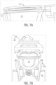
- FIG. 8A illustrates removal of the support structure 70 during the manufacturing process.
- FIG. 8B illustrates placement of panels (front panel 102 and one or more side panels 101) and cover 10 on the vertical frame 103 of toilet 100.
- the robot 80 couples at least one panel (e.g., front panel 102 and side panel 101) to the toilet 100.
- a lid panel 10 may be coupled to toilet seat assembly 13.
- the robot 80 installs the front lift plate 19 and the side lift plate 18 after removing the support structure 70.
- the robot 80 may turn the toilet 100 over (e.g., facing downward) then secure the front lift plate 19 and the side lift plate 18 using one or more fasteners.
- the front lift plate 19 and the side lift plate 18 may have various sizes (e.g., short, medium, or tall) in order to place the toilet 100 (e.g., seat 12) at a specific height.
- Various users may be comfortable at different sitting heights.
- the robot 80 may also attach a foot lever (e.g., foot pedal 29) to the toilet 100.
- the foot lever may include protrusion that are aligned with opening on the frame 103.
- the foot lever may be held in place by tension.
- the panels may couple to the toilet 100 in a variety of techniques.
- the panels may snap fit to the frame members 103.
- the panels may each include one or more tapered beams that mate with an opening of the frame members 103.
- the panels may each include a cavity with a pull perimeter snap ridge that mates with a protrusion or snap-in mound of the frame members 103.
- the panels may be fastened to the frame members 103 using a screw or bolt.
- the panels may be secured to the frame using magnets (i.e., each panel may include one or more magnets that align with one or more magnets of the frame members 103).
- the robot 80 may press the panels into the toilet 100 in order to connect the panels to the frame members 103.
- the panels may be attached and removed by the user.
- the user may press the panels to the toilet 100 in order to connect the panels to the frame members 103.
- the user may thread a fastener from the panels to the frame members 103.
- the panels may be swapped out by the user. That is, the user may remove one set of panels and install another set of panels.
- the panels may be formed of plastic or metal.
- An example plastic may be acrylonitrile butadiene styrene.
- An example metal may be aluminum.
- the panels may be formed using a 3D printer.
- the panels may include decals or stickers.
- the panels may be printed on using ink, paint, toner, or another substance that is applied on the panels from a nozzle.
- FIGS. 9A-9C illustrate a foot pedal 29 for the toilet 100.
- the foot pedal 29 controls the operation of the lid 10 and seat 12.
- the food pedal 29 may be connected to the lid 10 with a first drive train and connected to the seat 12 with a second drive train.
- a first press on the foot pedal 29 opens the lid 10 to a first angle.
- a second press opens the seat 12.
- a third press returns to lid 10 and the seat 12 to a closed position.
- a ratcheting mechanism may translate the vertical motion of the foot pedal 29 to rotational lift of the lid 10 and seat 12. The ratcheting mechanism is released by the third press to release the lid 10 and seat 12.
- FIG. 10 is an example remote control 120 for the toilet 100 of FIG. 1 and IFGS 9A-9C.
- the remote control 120 may include one or more buttons that cause a wireless signal (e.g. radio frequency signal) to the toilet 100 (e.g., remote control interface of the controller).
- the remote control 120 may include a first button, or first button position, for a partial flush or a half flush and a second button, or second button position, for a full flush. Additional buttons may be included for bidet operation, cleaning cycles, sleep (e.g., battery conservation) mode, or other features.
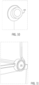
- FIG. 11 is an example local control 110 for the toilet 100 of FIG. 1 .
- the local control 110 may include one or more buttons that cause an electrical signal to the toilet 100 (e.g., local control interface of the controller).
- the local control 110 may include a first button position (e.g., halfway depressed) for a partial flush or a half flush and a second button position (e.g., substantially fully depressed) for a full flush.
- the local control 110 may generate a wireless signal that is transmitted to the controller of the toilet 100.
- FIG. 12 is an example foot control (e.g., kick input 20) for the toilet of FIG. 1 .
- the kick input 20 may include one or more buttons that cause an electrical signal (e.g. radio frequency signal) to the toilet 100 (e.g., controller).
- the kick input 10 may include a first button, or first button position, for a partial flush or a half flush and a second button, or second button position, for a full flush. Additional buttons may be included for cleaning cycles, sleep (e.g., battery conservation) mode, or other features.
- the kick input 20 may generate a wireless signal that is transmitted to the controller of the toilet 100.
- FIG. 13 is an example bidet 21 for the toilet 100 of FIG. 1 .
- the bidet 21 may spray water in response to a valve setting of the toilet 100.
- the bidet 21 may be actuated or spray water in response to any of the user inputs described above.
- the bidet 21 may be actuated on spray water in response to a flush cycle.
- FIG. 14 is an example light 22 for the toilet of FIG. 1 .
- the light 22 may be turned on in response to a light setting of the toilet 100.
- the light setting may indicate the light 22 is illuminated in response to any of the user inputs described above.
- the light 22 may be illuminated in response to a flush cycle.
- the light 22 may be illuminated in response to sensor data (e.g., a light sensor).
- the light 22 may be illuminated as a nightlight when the ambient light, or nearby lights, are turned off or below a predetermined threshold.
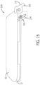
- FIG. 15 is an example open/close mechanism 200 for the lid 10 and seat 12 of the toilet 100.
- the open/close mechanism 200 may include a hook member 131 attached to the lid 10, a lock 134, and a release mechanism 135.
- the hook member 131 includes a pawl 132 engageable with the lock 134.
- the lock 134 is configured to hold the release mechanism 135. Additional, different, or fewer components may be included.
- FIGS. 16A-C illustrates a sequence for the open/close mechanism 200.
- the hook member 131 rotates until it makes contact with lock 134 at the guide surface 139 at a first angle.
- the lock 134 cannot rotated under the force from the hook member 131 because the lock 134 is pressed against the abutment surface 136 of the release mechanism 135, which is in the first position.
- the release mechanism 135 is rotated to a second position.
- the second position allows the lock 134 to rotate about its pivot point under force from the hook member 131.
- the pawl 132 moves along the lock 134 until a second surface of the pawl 132 meets the guide surface 139 of the lock 134, which moves the lid 10 toward a second angle.
- FIG. 16C at a seat open second position 213, the seat 12 is at the second angle.
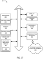
- FIG. 17 illustrates an example controller 301 for operation of the drive mechanism for seat 12 and lid 10.
- the controller 301 may include a processor 300, a memory 352, and a communication interface 353 for interfacing with devices or to the internet and/or other networks 346.
- a sensor interface may be configured to receive data from sensors (e.g., proximity sensors to trigger the operation of the seat 12 and/or lid 10; position sensors to detect the position of the seat 50 and/or cover).
- the controller 301 may include various inputs or interfaces for receiving electrical signals.
- a first interface may be connected to a foot input (e.g., kick panel 20).
- a second interface may be connected to a manual input (e.g., local control 110).
- a third interface e.g., communication interface 353) may be connected to a wireless input (e.g., Bluetooth or Wifi).
- the controller 301 is configured to generate a valve command in response to the foot input, the manual input, or the wireless input.
- a fourth interface may be connected to a sensor configured to detect presence of a user or motion of the user.
- control system may communicate using bus 348.
- the control system may be connected to a workstation or another external device (e.g., control panel) and/or a database for receiving user inputs, system characteristics, and any of the values described herein.
- control system may include an input device 355 and/or a sensing circuit 356 in communication with any of the sensors.
- the sensing circuit receives sensor measurements from sensors as described above.
- the sensors may detect the presence of the user, the identity of the user, or gestures from the user.
- the input device may include any of the user inputs such as buttons, touchscreen, a keyboard, a microphone for voice inputs, a camera for gesture inputs, and/or another mechanism.
- control system may include a drive unit 340 for receiving and reading non-transitory computer media 341 having instructions 342. Additional, different, or fewer components may be included.
- the processor 300 is configured to perform instructions 342 stored in memory 352 for executing the algorithms described herein.
- a display 350 may be an indicator or other screen output device. The display 350 may be combined with the user input device 355.
- FIG. 18 illustrates a flow chart for the apparatus of FIG. 17 .
- the acts of the flow chart may be performed by the controller 301. Additional, different of fewer acts may be included.
- the controller 301 identifies a presence or absence of a command signal from a remote control 120.
- the remote control 120 may send a wireless signal to the controller 301.
- the wireless signal may be in response to a button depressed or voice command announced by the user.
- the wireless signal may be in response to a sensor included on the remote control 120.
- Other sensors may be used.
- the sensor may include any type of sensor configured to detect certain conditions and/or to provide functionality. Odor sensors, proximity sensors, and motion sensors are non-limiting examples of sensors that may be employed with the systems of this application. Proximity sensors may be employed to detect the presence of an object within a zone of detection without physical contact between the object and the sensor.
- Electric potential sensors capacitance sensors, projected capacitance sensors, and infrared sensors (e.g., projected infrared sensors, passive infrared sensors) are non-limiting examples of proximity sensors that may be employed with the systems of this application.
- Motion sensors may be employed to detect motion (e.g., a change in position of an object relative to the objects surroundings).
- the controller 301 identifies a presence or absence of a command signal from a local hand control 110.
- the user may press in the hand control 110 to cause generation and transmission of the command signal to the controller 301.
- the local hand control 110 may include a touchscreen, touch sensor, capacitive sensor, electric potential sensors, optic sensors, radio-frequency (RF) sensors, sound sensors, magnetic sensors (e.g., magnetometers), vibration sensors, and/or infrared sensors (e.g., projected infrared sensors, passive infrared sensors).
- RF radio-frequency
- the controller 301 identifies a presence or absence of a command signal from a local foot control 29.
- the food pedal 29 may be connected to a pressure sensor that generates the command signal for the controller 301.
- the controller 301 may process the command signal from the remote control 120, the command signal from the local hand control 110, and/or the command signal from the local foot control 29. For example, when signals are received from any two devices, the controller 301 selects one command signal to override the second and/or third other command signals. The controller 301 may rank the foot control 29 to override the remote controller 120. The controller 301 may rank the local hand control 110 to override the remote controller 120 and the foot control 29. Other ranking techniques may be used.
- the controller 301 determines a motor command for a motor coupled to the lid 10 in response to one or more of the command signals.
- the motor command for the motor may indicate a preset level for lifting the lid 10.
- the lid 10 may be lifted the command signal from the remote control 120, the command signal from the local hand control 110, or the command signal from the local foot control 29. In other words, any user inputs or detection may cause the lid 10 to open.
- the controller 301 determines a motor command for a motor coupled to the seat 12 in response to one or more of the command signals.
- the controller 301 may cause the seat 12 to be opened when a user input, rather than sensor data alone, is received at the controller 301.
- the user input may be a keypress at the remote control 120, a touch at the local hand control 110, or a kick at the local foot control 29.
- the motor command for the motor may indicate a preset level for lifting the seat 12.
- Processor 300 may be a general purpose or specific purpose processor, an application specific integrated circuit (ASIC), one or more programmable logic controllers (PLCs), one or more field programmable gate arrays (FPGAs), a group of processing components, or other suitable processing components.
- Processor 300 is configured to execute computer code or instructions stored in memory 352 or received from other computer readable media (e.g., embedded flash memory, local hard disk storage, local ROM, network storage, a remote server, etc.).
- the processor 300 may be a single device or combinations of devices, such as associated with a network, distributed processing, or cloud computing.
- Memory 352 may include one or more devices (e.g., memory units, memory devices, storage devices, etc.) for storing data and/or computer code for completing and/or facilitating the various processes described in the present disclosure.
- Memory 352 may include random access memory (RAM), read-only memory (ROM), hard drive storage, temporary storage, non-volatile memory, flash memory, optical memory, or any other suitable memory for storing software objects and/or computer instructions.
- RAM random access memory
- ROM read-only memory
- ROM read-only memory
- Memory 352 may include database components, object code components, script components, or any other type of information structure for supporting the various activities and information structures described in the present disclosure.
- Memory 352 may be communicably connected to processor 300 via a processing circuit and may include computer code for executing (e.g., by processor 300) one or more processes described herein.
- the communication interface 353 may include any operable connection.
- An operable connection may be one in which signals, physical communications, and/or logical communications may be sent and/or received.
- An operable connection may include a physical interface, an electrical interface, and/or a data interface.
- the communication interface 353 may be connected to a network.
- the network may include wired networks (e.g., Ethernet), wireless networks, or combinations thereof.
- the wireless network may be a cellular telephone network, an 802.11, 802.16, 802.20, or WiMax network, a Bluetooth pairing of devices, or a Bluetooth mesh network.
- the network may be a public network, such as the Internet, a private network, such as an intranet, or combinations thereof, and may utilize a variety of networking protocols now available or later developed including, but not limited to TCP/IP based networking protocols.
- While the computer-readable medium (e.g., memory 352) is shown to be a single medium, the term “computer-readable medium” includes a single medium or multiple media, such as a centralized or distributed database, and/or associated caches and servers that store one or more sets of instructions.
- the term “computer-readable medium” shall also include any medium that is capable of storing, encoding or carrying a set of instructions for execution by a processor or that cause a computer system to perform any one or more of the methods or operations disclosed herein.
- the computer-readable medium can include a solid-state memory such as a memory card or other package that houses one or more non-volatile read-only memories. Further, the computer-readable medium can be a random access memory or other volatile re-writable memory. Additionally, the computer-readable medium can include a magneto-optical or optical medium, such as a disk or tapes or other storage device to capture carrier wave signals such as a signal communicated over a transmission medium. A digital file attachment to an e-mail or other self-contained information archive or set of archives may be considered a distribution medium that is a tangible storage medium.
- the disclosure is considered to include any one or more of a computer-readable medium or a distribution medium and other equivalents and successor media, in which data or instructions may be stored.
- the computer-readable medium may be non-transitory, which includes all tangible computer-readable media.
- dedicated hardware implementations such as application specific integrated circuits, programmable logic arrays and other hardware devices, can be constructed to implement one or more of the methods described herein.
- Applications that may include the apparatus and systems of various embodiments can broadly include a variety of electronic and computer systems.
- One or more embodiments described herein may implement functions using two or more specific interconnected hardware modules or devices with related control and data signals that can be communicated between and through the modules, or as portions of an application-specific integrated circuit. Accordingly, the present system encompasses software, firmware, and hardware implementations.
- inventions of the disclosure may be referred to herein, individually and/or collectively, by the term "invention" merely for convenience and without intending to voluntarily limit the scope of this application to any particular invention or inventive concept.
- inventions may be referred to herein, individually and/or collectively, by the term "invention" merely for convenience and without intending to voluntarily limit the scope of this application to any particular invention or inventive concept.
- specific embodiments have been illustrated and described herein, it should be appreciated that any subsequent arrangement designed to achieve the same or similar purpose may be substituted for the specific embodiments shown.
- This disclosure is intended to cover any and all subsequent adaptations or variations of various embodiments. Combinations of the above embodiments, and other embodiments not specifically described herein, will be apparent to those of skill in the art upon reviewing the description.
Landscapes
- Engineering & Computer Science (AREA)
- Health & Medical Sciences (AREA)
- Public Health (AREA)
- Life Sciences & Earth Sciences (AREA)
- Hydrology & Water Resources (AREA)
- Water Supply & Treatment (AREA)
- Aviation & Aerospace Engineering (AREA)
- Mechanical Engineering (AREA)
- Sanitary Device For Flush Toilet (AREA)
- Toilet Supplies (AREA)
Applications Claiming Priority (2)
| Application Number | Priority Date | Filing Date | Title |
|---|---|---|---|
| US202363452225P | 2023-03-15 | 2023-03-15 | |
| US18/597,663 US20240309624A1 (en) | 2023-03-15 | 2024-03-06 | Modular panel toilet |
Publications (2)
| Publication Number | Publication Date |
|---|---|
| EP4442915A2 true EP4442915A2 (de) | 2024-10-09 |
| EP4442915A3 EP4442915A3 (de) | 2024-12-04 |
Family
ID=90365483
Family Applications (1)
| Application Number | Title | Priority Date | Filing Date |
|---|---|---|---|
| EP24163374.2A Pending EP4442915A3 (de) | 2023-03-15 | 2024-03-13 | Modulare toilettenplatte |
Country Status (2)
| Country | Link |
|---|---|
| US (1) | US20240309624A1 (de) |
| EP (1) | EP4442915A3 (de) |
Cited By (1)
| Publication number | Priority date | Publication date | Assignee | Title |
|---|---|---|---|---|
| EP4636181A3 (de) * | 2024-04-15 | 2025-12-24 | Kohler Co. | Toilettenschale und rahmen |
Family Cites Families (9)
| Publication number | Priority date | Publication date | Assignee | Title |
|---|---|---|---|---|
| FR2282977A1 (fr) * | 1974-08-27 | 1976-03-26 | Fonderie Societe Generale | Procede et dispositif pour realiser par moulage des articles sanitaires, notamment des lavabos |
| US6353942B1 (en) * | 2000-11-16 | 2002-03-12 | Evac International Oy | Modular vacuum toilet with line replaceable units |
| US8978172B2 (en) * | 2009-11-17 | 2015-03-17 | Kohler Co. | Plumbing fixture having modular control housing |
| US9594500B2 (en) * | 2012-06-27 | 2017-03-14 | sigmund lindsay clements | Touch Free hygienic display control panel for a smart toilet |
| WO2014116732A1 (en) * | 2013-01-23 | 2014-07-31 | Kohler Co. | Smart toilet systems and methods |
| EP3418458A4 (de) * | 2016-02-19 | 2019-03-20 | Panasonic Intellectual Property Management Co., Ltd. | Toilette und toilettenherstellungsverfahren |
| CN215367629U (zh) * | 2020-12-01 | 2021-12-31 | 厦门建霖健康家居股份有限公司 | 一种双按钮冲水马桶 |
| DE102021108025A1 (de) * | 2021-03-30 | 2022-10-06 | Grohe Ag | Tragwerk für einen Sanitärartikel, Sanitärartikel-Set, WC-Becken und Verwendung eines Tragwerks |
| AU2021103588A4 (en) * | 2021-06-24 | 2021-08-12 | Bravat Global Pty Ltd | A toilet |
-
2024
- 2024-03-06 US US18/597,663 patent/US20240309624A1/en active Pending
- 2024-03-13 EP EP24163374.2A patent/EP4442915A3/de active Pending
Cited By (1)
| Publication number | Priority date | Publication date | Assignee | Title |
|---|---|---|---|---|
| EP4636181A3 (de) * | 2024-04-15 | 2025-12-24 | Kohler Co. | Toilettenschale und rahmen |
Also Published As
| Publication number | Publication date |
|---|---|
| EP4442915A3 (de) | 2024-12-04 |
| US20240309624A1 (en) | 2024-09-19 |
Similar Documents
| Publication | Publication Date | Title |
|---|---|---|
| US11834903B2 (en) | Motor assemblies for architectural coverings | |
| EP4442915A2 (de) | Modulare toilettenplatte | |
| US20170356218A1 (en) | Smart locker | |
| WO2017155998A1 (en) | Modular interface of intelligent lighting control apparatuses, systems, and methods | |
| US11280498B2 (en) | Retracting and extending control selectors | |
| US9996995B2 (en) | Door-lock control method | |
| CN112740640A (zh) | 用于物联网设备的消歧的系统和方法 | |
| US20140259927A1 (en) | Controller for a door operator | |
| US20240410154A1 (en) | Urinal | |
| US11982076B2 (en) | Magnetic water movement | |
| EP2907930B1 (de) | Fernsteuerungsvorrichtung | |
| JP6349688B2 (ja) | 無線通信システム、及びそれを備えたトイレ装置 | |
| CN118668787A (zh) | 模块化面板马桶 | |
| EP3475511A1 (de) | Verfahren zum einrichten eines türbetätigers und türbetätiger | |
| JP2016005140A (ja) | トイレ装置用のリモコン装置 | |
| EP4636181A2 (de) | Toilettenschale und rahmen | |
| EP4188175A1 (de) | Spülsystem und spülverfahren in interaktion mit einer toilettenabdeckung | |
| CN208183899U (zh) | 一种智能马桶的操控系统 | |
| US10241487B2 (en) | Control system for washroom devices | |
| KR101787890B1 (ko) | 변기용 물 내림장치 | |
| TW202206688A (zh) | 門的自動功能配置 | |
| US20250067035A1 (en) | Wall flush valve | |
| KR102795857B1 (ko) | 2채널 수신 | |
| US20240344358A1 (en) | Hands-free locking mechanism | |
| CN110593645A (zh) | 一种具有远程控制功能的智能门锁装置 |
Legal Events
| Date | Code | Title | Description |
|---|---|---|---|
| PUAI | Public reference made under article 153(3) epc to a published international application that has entered the european phase |
Free format text: ORIGINAL CODE: 0009012 |
|
| STAA | Information on the status of an ep patent application or granted ep patent |
Free format text: STATUS: THE APPLICATION HAS BEEN PUBLISHED |
|
| AK | Designated contracting states |
Kind code of ref document: A2 Designated state(s): AL AT BE BG CH CY CZ DE DK EE ES FI FR GB GR HR HU IE IS IT LI LT LU LV MC ME MK MT NL NO PL PT RO RS SE SI SK SM TR |
|
| PUAL | Search report despatched |
Free format text: ORIGINAL CODE: 0009013 |
|
| AK | Designated contracting states |
Kind code of ref document: A3 Designated state(s): AL AT BE BG CH CY CZ DE DK EE ES FI FR GB GR HR HU IE IS IT LI LT LU LV MC ME MK MT NL NO PL PT RO RS SE SI SK SM TR |
|
| RIC1 | Information provided on ipc code assigned before grant |
Ipc: E03D 5/04 20060101ALI20241029BHEP Ipc: E03D 11/14 20060101ALI20241029BHEP Ipc: E03D 11/13 20060101ALI20241029BHEP Ipc: E03D 5/10 20060101ALI20241029BHEP Ipc: E03D 5/09 20060101ALI20241029BHEP Ipc: E03D 5/08 20060101ALI20241029BHEP Ipc: A47K 13/26 20060101ALI20241029BHEP Ipc: A47K 13/10 20060101ALI20241029BHEP Ipc: E03D 11/02 20060101AFI20241029BHEP |
|
| STAA | Information on the status of an ep patent application or granted ep patent |
Free format text: STATUS: REQUEST FOR EXAMINATION WAS MADE |
|
| 17P | Request for examination filed |
Effective date: 20250501 |