EP4442504A1 - Seat frame - Google Patents
Seat frame Download PDFInfo
- Publication number
- EP4442504A1 EP4442504A1 EP22901740.5A EP22901740A EP4442504A1 EP 4442504 A1 EP4442504 A1 EP 4442504A1 EP 22901740 A EP22901740 A EP 22901740A EP 4442504 A1 EP4442504 A1 EP 4442504A1
- Authority
- EP
- European Patent Office
- Prior art keywords
- bracket
- plate
- seat frame
- rotating
- reinforcing
- Prior art date
- Legal status (The legal status is an assumption and is not a legal conclusion. Google has not performed a legal analysis and makes no representation as to the accuracy of the status listed.)
- Pending
Links
Images










Classifications
-
- B—PERFORMING OPERATIONS; TRANSPORTING
- B60—VEHICLES IN GENERAL
- B60N—SEATS SPECIALLY ADAPTED FOR VEHICLES; VEHICLE PASSENGER ACCOMMODATION NOT OTHERWISE PROVIDED FOR
- B60N2/00—Seats specially adapted for vehicles; Arrangement or mounting of seats in vehicles
- B60N2/02—Seats specially adapted for vehicles; Arrangement or mounting of seats in vehicles the seat or part thereof being movable, e.g. adjustable
- B60N2/04—Seats specially adapted for vehicles; Arrangement or mounting of seats in vehicles the seat or part thereof being movable, e.g. adjustable the whole seat being movable
- B60N2/16—Seats specially adapted for vehicles; Arrangement or mounting of seats in vehicles the seat or part thereof being movable, e.g. adjustable the whole seat being movable height-adjustable
- B60N2/1605—Seats specially adapted for vehicles; Arrangement or mounting of seats in vehicles the seat or part thereof being movable, e.g. adjustable the whole seat being movable height-adjustable characterised by the cinematic
- B60N2/161—Rods
- B60N2/1615—Parallelogram-like structure
-
- B—PERFORMING OPERATIONS; TRANSPORTING
- B60—VEHICLES IN GENERAL
- B60N—SEATS SPECIALLY ADAPTED FOR VEHICLES; VEHICLE PASSENGER ACCOMMODATION NOT OTHERWISE PROVIDED FOR
- B60N2/00—Seats specially adapted for vehicles; Arrangement or mounting of seats in vehicles
- B60N2/02—Seats specially adapted for vehicles; Arrangement or mounting of seats in vehicles the seat or part thereof being movable, e.g. adjustable
- B60N2/0224—Non-manual adjustments, e.g. with electrical operation
- B60N2/02246—Electric motors therefor
-
- B—PERFORMING OPERATIONS; TRANSPORTING
- B60—VEHICLES IN GENERAL
- B60N—SEATS SPECIALLY ADAPTED FOR VEHICLES; VEHICLE PASSENGER ACCOMMODATION NOT OTHERWISE PROVIDED FOR
- B60N2/00—Seats specially adapted for vehicles; Arrangement or mounting of seats in vehicles
- B60N2/02—Seats specially adapted for vehicles; Arrangement or mounting of seats in vehicles the seat or part thereof being movable, e.g. adjustable
- B60N2/0224—Non-manual adjustments, e.g. with electrical operation
- B60N2/02246—Electric motors therefor
- B60N2/02253—Electric motors therefor characterised by the transmission between the electric motor and the seat or seat parts
-
- B—PERFORMING OPERATIONS; TRANSPORTING
- B60—VEHICLES IN GENERAL
- B60N—SEATS SPECIALLY ADAPTED FOR VEHICLES; VEHICLE PASSENGER ACCOMMODATION NOT OTHERWISE PROVIDED FOR
- B60N2/00—Seats specially adapted for vehicles; Arrangement or mounting of seats in vehicles
- B60N2/02—Seats specially adapted for vehicles; Arrangement or mounting of seats in vehicles the seat or part thereof being movable, e.g. adjustable
- B60N2/04—Seats specially adapted for vehicles; Arrangement or mounting of seats in vehicles the seat or part thereof being movable, e.g. adjustable the whole seat being movable
- B60N2/06—Seats specially adapted for vehicles; Arrangement or mounting of seats in vehicles the seat or part thereof being movable, e.g. adjustable the whole seat being movable slidable
- B60N2/07—Slide construction
- B60N2/0722—Constructive details
-
- B—PERFORMING OPERATIONS; TRANSPORTING
- B60—VEHICLES IN GENERAL
- B60N—SEATS SPECIALLY ADAPTED FOR VEHICLES; VEHICLE PASSENGER ACCOMMODATION NOT OTHERWISE PROVIDED FOR
- B60N2/00—Seats specially adapted for vehicles; Arrangement or mounting of seats in vehicles
- B60N2/02—Seats specially adapted for vehicles; Arrangement or mounting of seats in vehicles the seat or part thereof being movable, e.g. adjustable
- B60N2/04—Seats specially adapted for vehicles; Arrangement or mounting of seats in vehicles the seat or part thereof being movable, e.g. adjustable the whole seat being movable
- B60N2/14—Seats specially adapted for vehicles; Arrangement or mounting of seats in vehicles the seat or part thereof being movable, e.g. adjustable the whole seat being movable rotatable, e.g. to permit easy access
-
- B—PERFORMING OPERATIONS; TRANSPORTING
- B60—VEHICLES IN GENERAL
- B60N—SEATS SPECIALLY ADAPTED FOR VEHICLES; VEHICLE PASSENGER ACCOMMODATION NOT OTHERWISE PROVIDED FOR
- B60N2/00—Seats specially adapted for vehicles; Arrangement or mounting of seats in vehicles
- B60N2/02—Seats specially adapted for vehicles; Arrangement or mounting of seats in vehicles the seat or part thereof being movable, e.g. adjustable
- B60N2/04—Seats specially adapted for vehicles; Arrangement or mounting of seats in vehicles the seat or part thereof being movable, e.g. adjustable the whole seat being movable
- B60N2/16—Seats specially adapted for vehicles; Arrangement or mounting of seats in vehicles the seat or part thereof being movable, e.g. adjustable the whole seat being movable height-adjustable
-
- B—PERFORMING OPERATIONS; TRANSPORTING
- B60—VEHICLES IN GENERAL
- B60N—SEATS SPECIALLY ADAPTED FOR VEHICLES; VEHICLE PASSENGER ACCOMMODATION NOT OTHERWISE PROVIDED FOR
- B60N2/00—Seats specially adapted for vehicles; Arrangement or mounting of seats in vehicles
- B60N2/68—Seat frames
-
- B—PERFORMING OPERATIONS; TRANSPORTING
- B60—VEHICLES IN GENERAL
- B60N—SEATS SPECIALLY ADAPTED FOR VEHICLES; VEHICLE PASSENGER ACCOMMODATION NOT OTHERWISE PROVIDED FOR
- B60N2/00—Seats specially adapted for vehicles; Arrangement or mounting of seats in vehicles
- B60N2/68—Seat frames
- B60N2/688—Particular seat belt attachment and guiding
-
- B—PERFORMING OPERATIONS; TRANSPORTING
- B60—VEHICLES IN GENERAL
- B60N—SEATS SPECIALLY ADAPTED FOR VEHICLES; VEHICLE PASSENGER ACCOMMODATION NOT OTHERWISE PROVIDED FOR
- B60N2/00—Seats specially adapted for vehicles; Arrangement or mounting of seats in vehicles
- B60N2/70—Upholstery springs ; Upholstery
-
- B—PERFORMING OPERATIONS; TRANSPORTING
- B60—VEHICLES IN GENERAL
- B60N—SEATS SPECIALLY ADAPTED FOR VEHICLES; VEHICLE PASSENGER ACCOMMODATION NOT OTHERWISE PROVIDED FOR
- B60N2/00—Seats specially adapted for vehicles; Arrangement or mounting of seats in vehicles
- B60N2/02—Seats specially adapted for vehicles; Arrangement or mounting of seats in vehicles the seat or part thereof being movable, e.g. adjustable
- B60N2/04—Seats specially adapted for vehicles; Arrangement or mounting of seats in vehicles the seat or part thereof being movable, e.g. adjustable the whole seat being movable
- B60N2/06—Seats specially adapted for vehicles; Arrangement or mounting of seats in vehicles the seat or part thereof being movable, e.g. adjustable the whole seat being movable slidable
- B60N2/07—Slide construction
- B60N2/0702—Slide construction characterised by its cross-section
- B60N2/0705—Slide construction characterised by its cross-section omega-shaped
-
- B—PERFORMING OPERATIONS; TRANSPORTING
- B60—VEHICLES IN GENERAL
- B60N—SEATS SPECIALLY ADAPTED FOR VEHICLES; VEHICLE PASSENGER ACCOMMODATION NOT OTHERWISE PROVIDED FOR
- B60N2/00—Seats specially adapted for vehicles; Arrangement or mounting of seats in vehicles
- B60N2/02—Seats specially adapted for vehicles; Arrangement or mounting of seats in vehicles the seat or part thereof being movable, e.g. adjustable
- B60N2/04—Seats specially adapted for vehicles; Arrangement or mounting of seats in vehicles the seat or part thereof being movable, e.g. adjustable the whole seat being movable
- B60N2/06—Seats specially adapted for vehicles; Arrangement or mounting of seats in vehicles the seat or part thereof being movable, e.g. adjustable the whole seat being movable slidable
- B60N2/07—Slide construction
- B60N2/0722—Constructive details
- B60N2/0725—Closing members for covering the slide
Definitions
- the present disclosure relates to a seat frame.
- a seat used in a vehicle may include a seat frame including a cushion part supporting the occupant's buttocks from below, and a seat back supporting the occupant's back from behind.
- the seat frame of the vehicle seat moves forward and backward or goes up and down on a rail part, and the seat back may be installed on the seat frame to be able to adjust an angle thereof to lie down or stand up.
- Vehicle seats need to be able to adjust the height and rotate of the seat frame at the same time for the convenience of the occupants.
- a seat frame that may stably satisfy load conditions such as collision or the like while allowing height adjustment and rotation of the seat frame has not been developed.
- Patent Document 1 KR 10-1998-0008730 A
- An aspect of the present disclosure is to provide a seat frame that may stably satisfy load conditions such as collisions or the like while allowing rotation and height adjustment.
- a seat frame includes a cushion part having a cushion; a height-adjusting part installed on a lower side of the cushion part and adjusting a height of the cushion part via a plurality of rotating links; a rotating part installed below the height-adjusting part and rotating the height-adjusting part and the cushion part; and a reinforcing bracket part coupled to a lower side of the rotating part, reinforcing the rotating part, and installed across a pair of rails of a rail part disposed on a lower side and spaced apart from each other.
- the height-adjusting part may include a first link connecting the rotating part and the cushion part at a front portion; and a second link connecting the rotating part and the cushion part at a rear portion.
- the rotating part may include a fixed plate disposed on a lower side; a base plate joined to an upper side of the fixed plate; and a rotating plate rotatably installed between the fixed plate and the base plate.
- the rotating part may further include a connection bracket having one side coupled to an upper side of the rotating plate and the other side coupled to the first link and the second link.
- connection bracket may have a first connection reinforcing portion installed in front of the connection bracket and forming a closed cross-section with the connection bracket.
- connection bracket may have a second connection reinforcing portion installed at a rear portion of the connection bracket and forming a closed cross-section with the connection bracket.
- connection bracket may be provided with a seat belt fixed to a rear upper side thereof, and the second connection reinforcing portion is coupled to a rear lower side of the connection bracket.
- the rotating part may further include a motor plate fixed to an upper side of the rotating plate: and a motor member installed on the motor plate and equipped with a drive gear engaged with a big gear fixed to the base plate.
- the reinforcing bracket part may include a bracket plate installed across the pair of rails and comprised of a single member coupled to the fixed plate; and a bracket reinforcing member coupled between the fixed plate and the bracket plate and comprised of a single member reinforcing the bracket plate.
- the bracket plate may be reinforced by overlapping the bracket reinforcing member on an upper side thereof, and the fixed plate of the rotating part is coupled to an upper side of the bracket reinforcing member.
- the bracket plate, the bracket reinforcing member, and the fixed plate of the rotating part may have lengths corresponding to each other in a front-to-back direction, and may have longitudinal overlapping sections overlapping and fixed to each other in a up and down direction.
- the bracket reinforcing member may extend in a front-to-back direction along the rails, and may have a reinforcing bead protruding upwardly in front of the bracket reinforcing member.
- the reinforcing bead may be disposed on a lower side of the rotating plate, when taken in plan view.
- the seat frame of the present disclosure is illustrated in the left and right direction, up and down direction, and front-to-back direction, and the terminology of left and right direction, up and down direction, and front-to-back direction is also used in the detailed description of the invention, but this is for convenience of explanation, and it should be noted that the technical features of the seat frame of the present disclosure are not limited to this direction.
- the X-axis illustrated in the attached drawings is the front-to-back direction of the seat frame
- the Y-axis is the left and right direction of the seat frame
- the Z-axis is the up and down direction of the seat frame.
- the seat frame 10 may include a cushion part 100, a height-adjusting part 200, a rotating part 300, and a reinforcing bracket part 400.
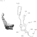
- FIG. 1 is a perspective view illustrating a seat in which the seat frame 10 and a seat back 20 of the present disclosure are combined.
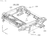
- FIGS. 2A and 2B are diagrams illustrating the operating state of the height-adjusting part 200 of the seat frame 10 of the present disclosure
- FIG. 3 is a perspective view of the cushion part 100 and the height-adjusting part 200 of the seat frame 10 of the present disclosure in an exploded state.
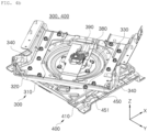
- FIGS. 4A and 4B are diagrams illustrating the operating state of the rotating part 300 of the seat frame 10 of the present disclosure
- FIG. 5 is a perspective view of the rotating part 300 and the reinforcing bracket part 400 of the seat frame 10 of the present disclosure in an exploded state
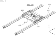
- FIG. 6 is a perspective view of the reinforcing bracket part 400 and a rail part 500 of the seat frame 10 of the present disclosure.
- the cushion part 100 may support a cushion.
- the cushion part 100 may be installed with a cushion for the driver to sit on, and the cushion part 100 is rotatably fixed to the seat back 20 of the seat so that the angle of the seat back 20 may be adjusted.
- the cushion part 100 may include components such as a cushion panel 110, a cushion side frame 120, a cushion side patch 130, a front pipe 140, a rear pipe 150, and the like.
- the front pipe 140 of the cushion part 100 is installed in front of the cushion part 100 to reinforce the cushion part 100, and the front pipe 140 may extend in the left and right directions.
- the rear pipe 150 of the cushion part 100 may be installed at the rear of the cushion part 100 to reinforce the cushion part 100, and the rear pipe 150 may extend in the left and right directions and may be installed by penetrating through a second link member 221 of the height-adjusting part 200, which will be described later.
- the height-adjusting part 200 is installed on the lower side of the cushion part 100, and may adjust the height of the cushion part 100 via a plurality of links.
- the link may include a first link 210 and a second link 220.
- the rotating part 300 is installed below the height-adjusting part 200 and may rotate the height-adjusting part 200 and the cushion part 100.
- the reinforcing bracket part 400 is coupled to the lower side of the rotating part 300 to reinforce the rotating part 300, and may be installed across a pair of rails 510 of the spaced apart rail part 500 located on the lower side.
- the reinforcing bracket part 400 may be installed across a pair of rails 510 disposed to be spaced apart in the left and right directions.
- the reinforcing bracket part 400 is fixed to a slide bracket 520 of the rail part 500, and the slide bracket 520 may be movably installed on the upper side of the rail 510.
- the rail part 500 is installed so that the seat frame 10 may move in the forward and backward directions, and the rotating part 300 may be movably installed on the rail part 500.
- the lower part of the rail part 500 may be fixed to the floor inside the vehicle, and the rotating part 300 may be fixed to the upper part thereof.
- a pair of rails 510 may be installed in the rail part 500, and the slide bracket 520 may be installed on the upper side of the pair of rails 510.
- the height-adjusting part 200 may include the first link 210 and the second link 220.
- the first link 210 may connect the rotating part 300 and the cushion part 100 at the front.
- the lower part of the first link 210 is connected to the front of the rotating part 300, and the upper part thereof may be connected to the front of the cushion part 100.
- the first link 210 may be installed in pairs spaced apart in the left and right directions.
- the upper side of the first link 210 is rotatably coupled to the cushion part 100, and the lower side thereof may be rotatably coupled to the rotating part 300. Specifically, the lower side of the first link 210 may be rotatably coupled to a connection bracket 340 of the rotating part 300.
- the second link 220 may connect the rotating part 300 and the cushion part 100 at the rear.
- the lower part of the second link 220 is connected to the rear of the rotating part 300, and the upper part thereof may be connected to the rear of the cushion part 100.
- the second link 220 may be installed in pairs spaced apart in the left and right directions.
- the second link 220 may include a second link member 221 and a second link bracket 222.
- the upper side of the second link member 221 is rotatably coupled to the cushion part 100, and the lower side thereof may be rotatably coupled to the rotating part 300.
- the second link bracket 222 is fixed to the upper side of the rotating part 300, and may be rotatably coupled to the lower side of the second link member 221.
- the second link member 221 and the second link bracket 222 disposed on the left and the second link member 221 and the second link bracket 222 disposed on the right may have slightly different shapes.
- the rotating part 300 may include a fixed plate 310, a base plate 330, and a rotating plate 320.
- the fixed plate 310 may be disposed in the lower side of the rotating part 300.
- a fixing reinforcing portion 311 is attached to the lower side of the fixed plate 310 to form a closed cross-section, thereby reinforcing the rigidity of the fixed plate 310.
- the base plate 330 may be joined to the upper side of the fixed plate 310.
- the rotating plate 320 may be disposed on the upper side of the rotating part 300.
- the rotating plate 320 may rotate on the upper side of the fixed plate 310.
- the rotating plate 320 may be installed between the fixed plate 310 and the base plate 330 to be rotatable in the circumferential direction.
- the rotating plate 320 may be prevented from being separated by the fixed plate 310 therebelow and the base plate 330 thereabove, and may rotate in the circumferential direction based on a rotation axis in the up and down direction.
- a ball bearing may be disposed between the rotating plate 320 and the fixed plate 310 therebelow.
- the fixed plate 310, the ball bearing, and the rotating plate 320 may be disposed sequentially from the bottom.
- a ball bearing may be disposed between the rotating plate 320 and the base plate 330 thereabove.
- the rotating plate 320, the ball bearing, and the base plate 330 may be disposed sequentially from the bottom.
- a ball bearing is provided between the fixed plate 310 and the rotating plate 320, so that the rotating plate 320 may be rotated with minimal rotational resistance.
- a ball bearing is provided between the base plate 330 and the rotating plate 320, so that the rotating plate 320 may be rotated with minimal rotation resistance.
- the rotating part 300 may further include the connection bracket 340.
- connection bracket 340 may be coupled to the upper side of the rotating plate 320, and the other side thereof may be coupled to the first link 210 and the second link 220.
- a pair of connection brackets 340 may be installed to be spaced apart in the left and right directions.
- connection bracket 340 may include a connection bottom plate 341 and a connection side plate 342.
- connection bottom plate 341 is coupled to the upper side of the rotating plate 320 and may be formed to extend in the transverse direction.
- the connection side plate 342 extends in the longitudinal direction to cross one side of the connection bottom plate 341, and may be coupled to the first link 210 and the second link 220.
- the lower portion of the first link 210 may be rotatably coupled to the front of the connection side plate 342, and the lower portion of the second link 220 may be rotatably coupled to the rear of the connection side plate 342.
- the first link 210 and the second link 220 may be coupled to the upper region of the connection side plate 342 in the up and down direction.
- connection brackets 340 are installed on the upper side of the rotating plate 320, to be spaced apart in the left and right directions, and the connection side plate 342 may be formed to extend upwardly from the connection bottom plate 341 in a crossing direction.
- FIG. 7 is a cross-sectional view in the '1' direction of the seat frame 10 of the present disclosure.
- connection bracket 340 may have a first connection reinforcing portion 343 that is installed in front of the connection bracket 340 and forms a closed cross-section with the connection bracket 340.
- the first connection reinforcing portion 343 is installed in front of the connection bracket 340 and may be fixed to the inner surface of the connection bracket 340 in the left and right directions.
- the first connection reinforcing portion 343 may form a closed cross-section together with the connection bottom plate 341 and the connection side plate 342 of the connection bracket 340.
- connection bottom plate 341 and the connection side plate 342 of the connection bracket 340 together have an 'L-shaped' cross-section
- first connection reinforcing portion 343 may have an 'L-shaped' cross-section with an inclined section formed in the corner portion.
- a closed cross-section in the shape of a right triangle may be formed between the inclined section of the first connection reinforcing portion 343 and the connection bracket 340.
- the first connection reinforcing portion 343 is installed around the first link 210 to reinforce the rigidity of the peripheral portion where the first link 210 is coupled.
- the first link 210 may be coupled to the front of the connection bracket 340.
- the first connection reinforcing portion 343 forms a closed cross-section together with the connection bracket 340 to reinforce the rigidity of the peripheral portion where the first link 210 is coupled.
- the first link 210 is coupled to the upper side of the connection bracket 340 in the height direction, and the first connection reinforcing portion 343 may be coupled to the lower side of the portion to which the first link 210 is coupled, so as not to cause interference with the first link 210.
- FIG. 8 is a cross-sectional view in the '2' direction of the seat frame 10 of the present disclosure
- FIG. 9 is a cross-sectional view in the '3' direction of the seat frame 10 of the present disclosure.
- connection bracket 340 may have a second connection reinforcing portion 344 that is installed at the rear of the connection bracket 340 and forms a closed cross-section together with the connection bracket 340.
- the second connection reinforcing portion 344 is installed at the rear of the connection bracket 340, and may be fixed to the outer surface of the connection bracket 340 in the left and right directions.
- the second connection reinforcing portion 344 may form a closed cross-section together with the connection side plate 342 of the connection bracket 340.
- connection bracket 340 and the second connection reinforcing portion 344 form a closed cross-section
- the connection bracket 340 may have a 'step-shaped' cross-section and the second connection reinforcing portion 344 may have an ⁇ L-shaped' cross-section.
- the second connection reinforcing portion 344 is installed around the second link 220 to reinforce the rigidity of the peripheral portion to which the second link 220 is coupled.
- the rotating plate 320, the connection bracket 340, and the second link 220 may be sequentially connected and fixed from the bottom to the top. Accordingly, the second connection reinforcing portion 344 may be coupled to the rear lower side of the connection bracket 340 and may not cause interference with the second link 220 connected to the upper side of the connection bracket 340. The second connection reinforcing portion 344 may form a closed cross-section with the connection bracket 340 to reinforce the rigidity of the peripheral portion to which the second link 220 is coupled.
- a belt fixture (T) is fixed to the rear upper side of the connection bracket 340, and the second connection reinforcing portion 344 may be coupled to the rear lower side of the connection bracket 340.
- connection brackets 340 may be installed to be spaced apart in the left and right directions, and the belt fixture (T) to which a seat belt (V) is fixed may respectively be formed on the rear upper sides of the connection brackets 340 on both sides.
- the belt fixture (T) disposed on the left and the belt fixture (T) disposed on the right may have slightly different shapes.
- the belt fixture (T) placed on the right is a seat belt buckle (T1, see FIG. 8 ), and the belt fixture (T) placed on the left is a seat belt anchor (T2, see FIG. 9 ), and the two may have different shapes.
- the cushion side patch 130 is combined with the cushion side frame 120 to form a closed cross-section, so that rigidity may be strengthened, the seat belt buckle (T1) may be coupled to the second link bracket 222, and the second link bracket 222 may be fixed to the upper side of the connection side plate 342 of the connection bracket 340.
- connection reinforcing portion 344 is installed around the belt fixture (T), and forms a closed cross-section with the connection bracket 340, to reinforce the rigidity around the belt fixture (T) to which the seat belt (V) is fixed.
- the belt fixture (T) is installed on the rear upper side of the connection bracket 340, and the second connection reinforcing portion 344 is installed on the lower side of the connection bracket 340 so that the second connection reinforcing portion 344 does not interfere with the belt fixture (T).
- FIG. 10 is a cross-sectional view of the seat frame 10 of the present disclosure in the ⁇ 4' direction.
- One side of the base plate 330 is coupled to the upper side of the fixed plate 310, and the other side thereof is installed to cover the upper portion of the rotating plate 320 disposed on the upper side of the fixed plate 310, to prevent the rotating plate 320 from being separated.
- the rotating part 300 may further include a motor plate 380 and a motor member 390.
- the motor plate 380 may be fixed to the upper side of the rotating plate 320.
- the motor member 390 may be installed on the motor plate 380 and have a drive gear 391 meshed with a big gear 331 fixed to the base plate 330.
- the big gear 331 has a gear surface formed on the inner peripheral surface thereof, and the drive gear 391 may be placed inside the big gear 331 and meshed therewith.
- the rotating plate 320 may be rotatably disposed between the fixed plate 310 and the base plate 330.
- the motor plate 380 on which the motor member 390 is installed may be fixed to the upper side of the rotating plate 320. As the drive gear 391 of the motor member 390 rotates while engaged with the big gear 331 coupled to the base plate 330, the motor plate 380 on which the motor is installed and the rotating plate 320 coupled to the motor plate 380 may be rotated.
- the drive gear 391 is meshed with a rotating gear 393 installed on the rotation axis of the motor member 390 and receives rotational force from the motor member 390, and the drive gear 391 may be meshed with the big gear 331.
- a pair of connection brackets 340 and the motor plate 380 may be installed on the upper side of the rotating plate 320.
- a pair of connection brackets 340 are installed on the upper side of the rotating plate 320, to be spaced apart in the left and right directions, and the motor plate 380 extending in the forward and backward directions may be disposed in the center portion in the left and right directions between the pair of connection brackets 340.
- FIG. 10 is a cross-sectional view of the seat frame 10 of the present disclosure in the '4' direction
- FIG. 11 is a cross-sectional view of the seat frame 10 of the present disclosure in the '5' direction.
- the reinforcing bracket part 400 may include a bracket plate 410 and a bracket reinforcing member 450.
- the bracket plate 410 is installed across a pair of rails 510, and may be comprised of a single member coupled to the fixed plate 310.
- the bracket plate 410 may be extended so that left and right ends thereof are disposed on the upper sides of the rails 510 on both sides.
- a motor bracket 530, a slide bracket 520, and a rail 510 may be placed on the lower side of the bracket plate 410.
- the slide bracket 520 may be movably installed on the rail 510, and the slide bracket 520 forms a locking structure with the rail 510, so that the slide bracket 520 may be prevented from being separated from the rail 510.
- the bracket reinforcing member 450 is coupled between the fixed plate 310 and the bracket plate 410 and may be comprised of a single member that reinforces the bracket plate 410.
- the bracket reinforcing member 450 may be comprised of a single member coupled between the fixed plate 310 and the bracket plate 410.
- a pair of bracket reinforcing members 450 may be installed on the bracket plate 410.
- the bracket reinforcing member 450 may be coupled to the left and right sides of the bracket plate 410, respectively.
- the upper side of the bracket plate 410 is reinforced by overlapping the bracket reinforcing member 450, and the fixed plate 310 of the rotating part 300 may be coupled to the upper side of the bracket reinforcing member 450.
- the upper side of the bracket plate 410 is reinforced by being combined with the bracket reinforcing member 450, and the motor bracket 530 and the slide bracket 520 may be coupled to the lower side of the bracket plate 410 reinforced by the bracket reinforcing member 450.
- the slide bracket 520, the motor bracket 530, the bracket plate 410, and the bracket reinforcing member 450 are disposed in order from the bottom to the top, and the fixed plate 310 may be coupled to the upper side of the bracket reinforcing member 450.
- the bracket plate 410, the bracket reinforcing member 450, and the fixed plate 310 of the rotating part 300 have lengths corresponding to each other in the front-to-back direction, and may be formed by overlapping each other in the up and down direction to form a fixed longitudinal overlap section.
- the bracket plate 410, the bracket reinforcing member 450, and the fixed plate 310 of the rotating part 300 may be fixed via bolts while overlapping each other in the up and down direction.
- the fixed plate 310 may be coupled to the bracket plate 410 reinforced by the bracket reinforcing member 450.
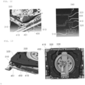
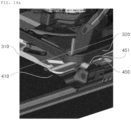
- FIG. 12 is a perspective view and a cross-sectional view of the portion where reinforcing bead 451 is formed in the seat frame 10 of the present disclosure, in the '6' direction.
- the bracket reinforcing member 450 extends in the front-to-back direction along the rail 510, and may have a reinforcing bead 451 protruding upward in front of the bracket reinforcing member 450.
- the bracket reinforcing member 450 may be comprised of a single member installed in the front-to-back direction, which is the longitudinal direction of the rail 510.
- the reinforcing beads 451 may include a protruding surface protruding upwardly, and an inclined surface formed on both sides of the protruding surface in the front-to-back direction and sloping downward in the front to back direction.
- the slide bracket 520 may be installed to be movable on the rail 510, and the slide bracket 520 forms a locking structure with the rail 510, so that the slide bracket 520 may be prevented from being separated from the rail 510.
- FIG. 13 is a perspective view and a plan view of the portion where the reinforcing bead 451 is formed in the seat frame 10 of the present disclosure.
- the reinforcing bead 451 may be disposed on the lower side of the rotating plate 320 in a plane view.
- the left-right length of the front area of the rotating plate 320 may be longer than the left-right length of the rear area.
- the rotating plate 320 may have left and right ends disposed above the reinforcing bead 451 in the front area.
- the size of the rotating plate 320 may be reduced, which has the effect of reducing the weight of the part.
- FIGS. 14A and 14B are deformation analysis results of the seat frame 10 according to an embodiment of the present disclosure.
- FIG. 14A is the initial deformation analysis result of the example
- FIG. 14B is the later deformation analysis result of the example.
- FIGS. 15A and 15B show the results of deformation analysis of the seat frame 10 of the comparative example.
- FIG. 15A is the initial deformation analysis result of the comparative example
- FIG. 15B is the result of the later deformation analysis of the comparative example.
- the comparative example has a significant difference in that it does not include the configuration of the reinforcing bead 451 of the bracket reinforcing member 450 and the like, and there is also some difference in the shape of the bracket plate 410.
- the bracket reinforcing member 450 extends in the front-to-back directions along the rail 510 and has the reinforcing bead 451 protruding upward in front of the bracket reinforcing member 450, and the reinforcing bead 451 is disposed on the lower side of the rotating plate 320 on a plane, and thus it can be seen that that excessive deformation does not occur in the rotating plate 320 of the rotating part 300 and is stably supported even in the late stage of deformation.
- FIG. 16 is a cross-sectional view of the seat frame 10 of the present disclosure in the ⁇ 7' direction.
- the upper side of the bracket plate 410 is reinforced by overlapping the bracket reinforcing member 450, and the slide bracket 520 may be coupled to the lower side of the bracket plate 410.
- the slide bracket 520, the bracket plate 410, and the bracket reinforcing member 450 are disposed in order from the bottom to the top, and may be coupled via bolts.
- a bracket plate patch 460 is coupled to the longitudinal front bottom of the bracket plate 410 to prevent excessive deformation of the bracket plate 410.
Landscapes
- Engineering & Computer Science (AREA)
- Aviation & Aerospace Engineering (AREA)
- Transportation (AREA)
- Mechanical Engineering (AREA)
- Seats For Vehicles (AREA)
Abstract
Description
- The present disclosure relates to a seat frame.
- It should be noted that the content described in this section merely provides background information on the present disclosure and does not constitute prior art.
- In general, a seat used in a vehicle may include a seat frame including a cushion part supporting the occupant's buttocks from below, and a seat back supporting the occupant's back from behind.
- The seat frame of the vehicle seat moves forward and backward or goes up and down on a rail part, and the seat back may be installed on the seat frame to be able to adjust an angle thereof to lie down or stand up.
- Vehicle seats need to be able to adjust the height and rotate of the seat frame at the same time for the convenience of the occupants. However, to date, a seat frame that may stably satisfy load conditions such as collision or the like while allowing height adjustment and rotation of the seat frame has not been developed.
- (Patent Document 1)
KR 10-1998-0008730 A - An aspect of the present disclosure is to provide a seat frame that may stably satisfy load conditions such as collisions or the like while allowing rotation and height adjustment.
- According to an aspect of the present disclosure, a seat frame includes a cushion part having a cushion; a height-adjusting part installed on a lower side of the cushion part and adjusting a height of the cushion part via a plurality of rotating links; a rotating part installed below the height-adjusting part and rotating the height-adjusting part and the cushion part; and a reinforcing bracket part coupled to a lower side of the rotating part, reinforcing the rotating part, and installed across a pair of rails of a rail part disposed on a lower side and spaced apart from each other.
- The height-adjusting part may include a first link connecting the rotating part and the cushion part at a front portion; and a second link connecting the rotating part and the cushion part at a rear portion.
- The rotating part may include a fixed plate disposed on a lower side; a base plate joined to an upper side of the fixed plate; and a rotating plate rotatably installed between the fixed plate and the base plate.
- The rotating part may further include a connection bracket having one side coupled to an upper side of the rotating plate and the other side coupled to the first link and the second link.
- The connection bracket may have a first connection reinforcing portion installed in front of the connection bracket and forming a closed cross-section with the connection bracket.
- The connection bracket may have a second connection reinforcing portion installed at a rear portion of the connection bracket and forming a closed cross-section with the connection bracket.
- The connection bracket may be provided with a seat belt fixed to a rear upper side thereof, and the second connection reinforcing portion is coupled to a rear lower side of the connection bracket.
- The rotating part may further include a motor plate fixed to an upper side of the rotating plate: and a motor member installed on the motor plate and equipped with a drive gear engaged with a big gear fixed to the base plate.
- The reinforcing bracket part may include a bracket plate installed across the pair of rails and comprised of a single member coupled to the fixed plate; and a bracket reinforcing member coupled between the fixed plate and the bracket plate and comprised of a single member reinforcing the bracket plate.
- The bracket plate may be reinforced by overlapping the bracket reinforcing member on an upper side thereof, and the fixed plate of the rotating part is coupled to an upper side of the bracket reinforcing member.
- The bracket plate, the bracket reinforcing member, and the fixed plate of the rotating part may have lengths corresponding to each other in a front-to-back direction, and may have longitudinal overlapping sections overlapping and fixed to each other in a up and down direction.
- The bracket reinforcing member may extend in a front-to-back direction along the rails, and may have a reinforcing bead protruding upwardly in front of the bracket reinforcing member.
- The reinforcing bead may be disposed on a lower side of the rotating plate, when taken in plan view.
- According to an embodiment of the present disclosure, there is an effect of stably satisfying load conditions such as collisions or the like while allowing rotation and height adjustment.
-
-
FIG. 1 is a perspective view illustrating a seat in which a seat frame and a seat back of the present disclosure are combined. -
FIGS. 2A and2B are diagrams illustrating an operating state of a height-adjusting part of a seat frame of the present disclosure. -
FIG. 3 is a perspective view of a cushion part and a height-adjusting part of a seat frame of the present disclosure in an exploded state. -
FIGS. 4A and4B are diagrams illustrating an operating state of a rotating part of a seat frame of the present disclosure. -
FIG. 5 is a perspective view of a rotating part and a reinforcing bracket part of a seat frame of the present disclosure in an exploded state. -
FIG. 6 is a perspective view of a reinforcing bracket part and a rail part of a seat frame of the present disclosure. -
FIG. 7 is a cross-sectional view in a '1' direction of a seat frame of the present disclosure. -
FIG. 8 is a cross-sectional view in a '2' direction of a seat frame of the present disclosure. -
FIG. 9 is a cross-sectional view in a '3' direction of a seat frame of the present disclosure. -
FIG. 10 is a cross-sectional view in a '4' direction of a seat frame of the present disclosure. -
FIG. 11 is a cross-sectional view in a '5' direction of a seat frame of the present disclosure. -
FIG. 12 is a perspective view and a cross-sectional view of a portion in which reinforcing beads are formed, in a '6' direction, in a seat frame of the present disclosure. -
FIG. 13 is a perspective view and a plan view of a portion in which reinforcing beads are formed in a seat frame of the present disclosure. -
FIGS. 14A and14B illustrate results of deformation analysis of the seat frame of an embodiment of the present disclosure. -
FIGS. 15A and15B illustrate results of deformation analysis of a seat frame of the comparative example. -
FIG. 16 is a cross-sectional view of a seat frame of the present disclosure in the '7' direction. - Hereinafter, preferred embodiments of the present disclosure will be described with reference to the attached drawings. However, embodiments of the present disclosure may be modified in various other forms, and the scope of the present disclosure is not limited to the embodiments described below. Additionally, the embodiments of the present disclosure are provided to more completely explain the present disclosure to those with average knowledge in the relevant technical field. The shapes and sizes of elements in drawings may be exaggerated for clearer explanation.
- Referring to the drawings, the seat frame of the present disclosure is illustrated in the left and right direction, up and down direction, and front-to-back direction, and the terminology of left and right direction, up and down direction, and front-to-back direction is also used in the detailed description of the invention, but this is for convenience of explanation, and it should be noted that the technical features of the seat frame of the present disclosure are not limited to this direction.
- Hereinafter, the X-axis illustrated in the attached drawings is the front-to-back direction of the seat frame, the Y-axis is the left and right direction of the seat frame, and the Z-axis is the up and down direction of the seat frame.
- Hereinafter, components included in a
seat frame 10 according to an embodiment of the present disclosure will be described in detail with reference toFIGS. 1 to 6 . - The
seat frame 10 according to an embodiment of the present disclosure may include acushion part 100, a height-adjustingpart 200, a rotatingpart 300, and a reinforcingbracket part 400. -
FIG. 1 is a perspective view illustrating a seat in which theseat frame 10 and aseat back 20 of the present disclosure are combined. -
FIGS. 2A and2B are diagrams illustrating the operating state of the height-adjustingpart 200 of theseat frame 10 of the present disclosure, andFIG. 3 is a perspective view of thecushion part 100 and the height-adjustingpart 200 of theseat frame 10 of the present disclosure in an exploded state. -
FIGS. 4A and4B are diagrams illustrating the operating state of the rotatingpart 300 of theseat frame 10 of the present disclosure,FIG. 5 is a perspective view of therotating part 300 and the reinforcingbracket part 400 of theseat frame 10 of the present disclosure in an exploded state, andFIG. 6 is a perspective view of the reinforcingbracket part 400 and arail part 500 of theseat frame 10 of the present disclosure. - The
cushion part 100 may support a cushion. Thecushion part 100 may be installed with a cushion for the driver to sit on, and thecushion part 100 is rotatably fixed to theseat back 20 of the seat so that the angle of theseat back 20 may be adjusted. - The
cushion part 100 may include components such as acushion panel 110, acushion side frame 120, acushion side patch 130, afront pipe 140, arear pipe 150, and the like. - The
front pipe 140 of thecushion part 100 is installed in front of thecushion part 100 to reinforce thecushion part 100, and thefront pipe 140 may extend in the left and right directions. - The
rear pipe 150 of thecushion part 100 may be installed at the rear of thecushion part 100 to reinforce thecushion part 100, and therear pipe 150 may extend in the left and right directions and may be installed by penetrating through asecond link member 221 of the height-adjustingpart 200, which will be described later. - The height-adjusting
part 200 is installed on the lower side of thecushion part 100, and may adjust the height of thecushion part 100 via a plurality of links. As an example, the link may include afirst link 210 and asecond link 220. - The
rotating part 300 is installed below the height-adjustingpart 200 and may rotate the height-adjustingpart 200 and thecushion part 100. - The reinforcing
bracket part 400 is coupled to the lower side of therotating part 300 to reinforce therotating part 300, and may be installed across a pair ofrails 510 of the spaced apart railpart 500 located on the lower side. - The reinforcing
bracket part 400 may be installed across a pair ofrails 510 disposed to be spaced apart in the left and right directions. The reinforcingbracket part 400 is fixed to aslide bracket 520 of therail part 500, and theslide bracket 520 may be movably installed on the upper side of therail 510. - The
rail part 500 is installed so that theseat frame 10 may move in the forward and backward directions, and therotating part 300 may be movably installed on therail part 500. - The lower part of the
rail part 500 may be fixed to the floor inside the vehicle, and therotating part 300 may be fixed to the upper part thereof. A pair ofrails 510 may be installed in therail part 500, and theslide bracket 520 may be installed on the upper side of the pair ofrails 510. - The height-adjusting
part 200 may include thefirst link 210 and thesecond link 220. - The
first link 210 may connect therotating part 300 and thecushion part 100 at the front. The lower part of thefirst link 210 is connected to the front of therotating part 300, and the upper part thereof may be connected to the front of thecushion part 100. Thefirst link 210 may be installed in pairs spaced apart in the left and right directions. - The upper side of the
first link 210 is rotatably coupled to thecushion part 100, and the lower side thereof may be rotatably coupled to therotating part 300. Specifically, the lower side of thefirst link 210 may be rotatably coupled to aconnection bracket 340 of therotating part 300. - The
second link 220 may connect therotating part 300 and thecushion part 100 at the rear. The lower part of thesecond link 220 is connected to the rear of therotating part 300, and the upper part thereof may be connected to the rear of thecushion part 100. Thesecond link 220 may be installed in pairs spaced apart in the left and right directions. - The
second link 220 may include asecond link member 221 and asecond link bracket 222. - The upper side of the
second link member 221 is rotatably coupled to thecushion part 100, and the lower side thereof may be rotatably coupled to therotating part 300. - The
second link bracket 222 is fixed to the upper side of therotating part 300, and may be rotatably coupled to the lower side of thesecond link member 221. Thesecond link member 221 and thesecond link bracket 222 disposed on the left and thesecond link member 221 and thesecond link bracket 222 disposed on the right may have slightly different shapes. - The
rotating part 300 may include afixed plate 310, abase plate 330, and arotating plate 320. - The fixed
plate 310 may be disposed in the lower side of therotating part 300. Afixing reinforcing portion 311 is attached to the lower side of the fixedplate 310 to form a closed cross-section, thereby reinforcing the rigidity of the fixedplate 310. - The
base plate 330 may be joined to the upper side of the fixedplate 310. - The
rotating plate 320 may be disposed on the upper side of therotating part 300. Therotating plate 320 may rotate on the upper side of the fixedplate 310. - The
rotating plate 320 may be installed between thefixed plate 310 and thebase plate 330 to be rotatable in the circumferential direction. Therotating plate 320 may be prevented from being separated by the fixedplate 310 therebelow and thebase plate 330 thereabove, and may rotate in the circumferential direction based on a rotation axis in the up and down direction. - A ball bearing may be disposed between the
rotating plate 320 and the fixedplate 310 therebelow. The fixedplate 310, the ball bearing, and therotating plate 320 may be disposed sequentially from the bottom. - A ball bearing may be disposed between the
rotating plate 320 and thebase plate 330 thereabove. Therotating plate 320, the ball bearing, and thebase plate 330 may be disposed sequentially from the bottom. - A ball bearing is provided between the
fixed plate 310 and therotating plate 320, so that therotating plate 320 may be rotated with minimal rotational resistance. A ball bearing is provided between thebase plate 330 and therotating plate 320, so that therotating plate 320 may be rotated with minimal rotation resistance. - The
rotating part 300 may further include theconnection bracket 340. - One side of the
connection bracket 340 may be coupled to the upper side of therotating plate 320, and the other side thereof may be coupled to thefirst link 210 and thesecond link 220. A pair ofconnection brackets 340 may be installed to be spaced apart in the left and right directions. - The
connection bracket 340 may include aconnection bottom plate 341 and aconnection side plate 342. - The
connection bottom plate 341 is coupled to the upper side of therotating plate 320 and may be formed to extend in the transverse direction. Theconnection side plate 342 extends in the longitudinal direction to cross one side of theconnection bottom plate 341, and may be coupled to thefirst link 210 and thesecond link 220. - The lower portion of the
first link 210 may be rotatably coupled to the front of theconnection side plate 342, and the lower portion of thesecond link 220 may be rotatably coupled to the rear of theconnection side plate 342. Thefirst link 210 and thesecond link 220 may be coupled to the upper region of theconnection side plate 342 in the up and down direction. - A pair of
connection brackets 340 are installed on the upper side of therotating plate 320, to be spaced apart in the left and right directions, and theconnection side plate 342 may be formed to extend upwardly from theconnection bottom plate 341 in a crossing direction. -
FIG. 7 is a cross-sectional view in the '1' direction of theseat frame 10 of the present disclosure. - The
connection bracket 340 may have a firstconnection reinforcing portion 343 that is installed in front of theconnection bracket 340 and forms a closed cross-section with theconnection bracket 340. - The first
connection reinforcing portion 343 is installed in front of theconnection bracket 340 and may be fixed to the inner surface of theconnection bracket 340 in the left and right directions. The firstconnection reinforcing portion 343 may form a closed cross-section together with theconnection bottom plate 341 and theconnection side plate 342 of theconnection bracket 340. - The
connection bottom plate 341 and theconnection side plate 342 of theconnection bracket 340 together have an 'L-shaped' cross-section, and the firstconnection reinforcing portion 343 may have an 'L-shaped' cross-section with an inclined section formed in the corner portion. A closed cross-section in the shape of a right triangle may be formed between the inclined section of the firstconnection reinforcing portion 343 and theconnection bracket 340. - The first
connection reinforcing portion 343 is installed around thefirst link 210 to reinforce the rigidity of the peripheral portion where thefirst link 210 is coupled. - The
first link 210 may be coupled to the front of theconnection bracket 340. At this time, the firstconnection reinforcing portion 343 forms a closed cross-section together with theconnection bracket 340 to reinforce the rigidity of the peripheral portion where thefirst link 210 is coupled. - The
first link 210 is coupled to the upper side of theconnection bracket 340 in the height direction, and the firstconnection reinforcing portion 343 may be coupled to the lower side of the portion to which thefirst link 210 is coupled, so as not to cause interference with thefirst link 210. -
FIG. 8 is a cross-sectional view in the '2' direction of theseat frame 10 of the present disclosure, andFIG. 9 is a cross-sectional view in the '3' direction of theseat frame 10 of the present disclosure. - The
connection bracket 340 may have a secondconnection reinforcing portion 344 that is installed at the rear of theconnection bracket 340 and forms a closed cross-section together with theconnection bracket 340. - The second
connection reinforcing portion 344 is installed at the rear of theconnection bracket 340, and may be fixed to the outer surface of theconnection bracket 340 in the left and right directions. The secondconnection reinforcing portion 344 may form a closed cross-section together with theconnection side plate 342 of theconnection bracket 340. - When the
connection bracket 340 and the secondconnection reinforcing portion 344 form a closed cross-section, in the closed cross-section portion, theconnection bracket 340 may have a 'step-shaped' cross-section and the secondconnection reinforcing portion 344 may have an `L-shaped' cross-section. - The second
connection reinforcing portion 344 is installed around thesecond link 220 to reinforce the rigidity of the peripheral portion to which thesecond link 220 is coupled. - The
rotating plate 320, theconnection bracket 340, and thesecond link 220 may be sequentially connected and fixed from the bottom to the top. Accordingly, the secondconnection reinforcing portion 344 may be coupled to the rear lower side of theconnection bracket 340 and may not cause interference with thesecond link 220 connected to the upper side of theconnection bracket 340. The secondconnection reinforcing portion 344 may form a closed cross-section with theconnection bracket 340 to reinforce the rigidity of the peripheral portion to which thesecond link 220 is coupled. - A belt fixture (T) is fixed to the rear upper side of the
connection bracket 340, and the secondconnection reinforcing portion 344 may be coupled to the rear lower side of theconnection bracket 340. - A pair of
connection brackets 340 may be installed to be spaced apart in the left and right directions, and the belt fixture (T) to which a seat belt (V) is fixed may respectively be formed on the rear upper sides of theconnection brackets 340 on both sides. - The belt fixture (T) disposed on the left and the belt fixture (T) disposed on the right may have slightly different shapes. The belt fixture (T) placed on the right is a seat belt buckle (T1, see
FIG. 8 ), and the belt fixture (T) placed on the left is a seat belt anchor (T2, seeFIG. 9 ), and the two may have different shapes. - The
cushion side patch 130 is combined with thecushion side frame 120 to form a closed cross-section, so that rigidity may be strengthened, the seat belt buckle (T1) may be coupled to thesecond link bracket 222, and thesecond link bracket 222 may be fixed to the upper side of theconnection side plate 342 of theconnection bracket 340. - The second
connection reinforcing portion 344 is installed around the belt fixture (T), and forms a closed cross-section with theconnection bracket 340, to reinforce the rigidity around the belt fixture (T) to which the seat belt (V) is fixed. - The belt fixture (T) is installed on the rear upper side of the
connection bracket 340, and the secondconnection reinforcing portion 344 is installed on the lower side of theconnection bracket 340 so that the secondconnection reinforcing portion 344 does not interfere with the belt fixture (T). -
FIG. 10 is a cross-sectional view of theseat frame 10 of the present disclosure in the `4' direction. - One side of the
base plate 330 is coupled to the upper side of the fixedplate 310, and the other side thereof is installed to cover the upper portion of therotating plate 320 disposed on the upper side of the fixedplate 310, to prevent therotating plate 320 from being separated. - The
rotating part 300 may further include amotor plate 380 and amotor member 390. - The
motor plate 380 may be fixed to the upper side of therotating plate 320. - The
motor member 390 may be installed on themotor plate 380 and have adrive gear 391 meshed with abig gear 331 fixed to thebase plate 330. Thebig gear 331 has a gear surface formed on the inner peripheral surface thereof, and thedrive gear 391 may be placed inside thebig gear 331 and meshed therewith. - The
rotating plate 320 may be rotatably disposed between thefixed plate 310 and thebase plate 330. Themotor plate 380 on which themotor member 390 is installed may be fixed to the upper side of therotating plate 320. As thedrive gear 391 of themotor member 390 rotates while engaged with thebig gear 331 coupled to thebase plate 330, themotor plate 380 on which the motor is installed and therotating plate 320 coupled to themotor plate 380 may be rotated. - The
drive gear 391 is meshed with arotating gear 393 installed on the rotation axis of themotor member 390 and receives rotational force from themotor member 390, and thedrive gear 391 may be meshed with thebig gear 331. - A pair of
connection brackets 340 and themotor plate 380 may be installed on the upper side of therotating plate 320. A pair ofconnection brackets 340 are installed on the upper side of therotating plate 320, to be spaced apart in the left and right directions, and themotor plate 380 extending in the forward and backward directions may be disposed in the center portion in the left and right directions between the pair ofconnection brackets 340. As theconnection side plate 342 of theconnection bracket 340 extends upwardly from theconnection bottom plate 341 in a direction crossing therewith, a space for installation of themotor member 390 may be secured on the upper side of themotor plate 380. -
FIG. 10 is a cross-sectional view of theseat frame 10 of the present disclosure in the '4' direction, andFIG. 11 is a cross-sectional view of theseat frame 10 of the present disclosure in the '5' direction. - The reinforcing
bracket part 400 may include abracket plate 410 and abracket reinforcing member 450. - The
bracket plate 410 is installed across a pair ofrails 510, and may be comprised of a single member coupled to the fixedplate 310. Thebracket plate 410 may be extended so that left and right ends thereof are disposed on the upper sides of therails 510 on both sides. - A
motor bracket 530, aslide bracket 520, and arail 510 may be placed on the lower side of thebracket plate 410. - The
slide bracket 520 may be movably installed on therail 510, and theslide bracket 520 forms a locking structure with therail 510, so that theslide bracket 520 may be prevented from being separated from therail 510. - The
bracket reinforcing member 450 is coupled between thefixed plate 310 and thebracket plate 410 and may be comprised of a single member that reinforces thebracket plate 410. - The
bracket reinforcing member 450 may be comprised of a single member coupled between thefixed plate 310 and thebracket plate 410. - A pair of
bracket reinforcing members 450 may be installed on thebracket plate 410. Thebracket reinforcing member 450 may be coupled to the left and right sides of thebracket plate 410, respectively. - The upper side of the
bracket plate 410 is reinforced by overlapping thebracket reinforcing member 450, and the fixedplate 310 of therotating part 300 may be coupled to the upper side of thebracket reinforcing member 450. - The upper side of the
bracket plate 410 is reinforced by being combined with thebracket reinforcing member 450, and themotor bracket 530 and theslide bracket 520 may be coupled to the lower side of thebracket plate 410 reinforced by thebracket reinforcing member 450. - The
slide bracket 520, themotor bracket 530, thebracket plate 410, and thebracket reinforcing member 450 are disposed in order from the bottom to the top, and the fixedplate 310 may be coupled to the upper side of thebracket reinforcing member 450. - The
bracket plate 410, thebracket reinforcing member 450, and the fixedplate 310 of therotating part 300 have lengths corresponding to each other in the front-to-back direction, and may be formed by overlapping each other in the up and down direction to form a fixed longitudinal overlap section. - The
bracket plate 410, thebracket reinforcing member 450, and the fixedplate 310 of therotating part 300 may be fixed via bolts while overlapping each other in the up and down direction. The fixedplate 310 may be coupled to thebracket plate 410 reinforced by thebracket reinforcing member 450. -
FIG. 12 is a perspective view and a cross-sectional view of the portion where reinforcingbead 451 is formed in theseat frame 10 of the present disclosure, in the '6' direction. - The
bracket reinforcing member 450 extends in the front-to-back direction along therail 510, and may have a reinforcingbead 451 protruding upward in front of thebracket reinforcing member 450. Thebracket reinforcing member 450 may be comprised of a single member installed in the front-to-back direction, which is the longitudinal direction of therail 510. - The reinforcing
beads 451 may include a protruding surface protruding upwardly, and an inclined surface formed on both sides of the protruding surface in the front-to-back direction and sloping downward in the front to back direction. - By forming the reinforcing
bead 451 protruding upward in front of thebracket reinforcing member 450, theslide bracket 520 may be installed to be movable on therail 510, and theslide bracket 520 forms a locking structure with therail 510, so that theslide bracket 520 may be prevented from being separated from therail 510. -
FIG. 13 is a perspective view and a plan view of the portion where the reinforcingbead 451 is formed in theseat frame 10 of the present disclosure. - The reinforcing
bead 451 may be disposed on the lower side of therotating plate 320 in a plane view. - In a plane view, the left-right length of the front area of the
rotating plate 320 may be longer than the left-right length of the rear area. In addition, therotating plate 320 may have left and right ends disposed above the reinforcingbead 451 in the front area. - By placing the
rotating plate 320 on the upper side of the reinforcingbead 451 on a plane, when therotating plate 320 is deformed, therotating plate 320 is caught by the reinforcingbead 451 such that the lower portion of therotating plate 320 may be supported, thereby preventing therotating plate 320 from being excessively deformed. - By shortening the left and right lengths of the rear area of the
rotating plate 320 on a plane, the size of therotating plate 320 may be reduced, which has the effect of reducing the weight of the part. - Hereinafter, with reference to
FIGS. 14A to 15B , the effect of installing thebracket reinforcing member 450 and the reinforcingbead 451 of thebracket reinforcing member 450 in an embodiment of the present disclosure will be compared with the comparative example. -
FIGS. 14A and14B are deformation analysis results of theseat frame 10 according to an embodiment of the present disclosure.FIG. 14A is the initial deformation analysis result of the example, andFIG. 14B is the later deformation analysis result of the example. -
FIGS. 15A and15B show the results of deformation analysis of theseat frame 10 of the comparative example.FIG. 15A is the initial deformation analysis result of the comparative example, andFIG. 15B is the result of the later deformation analysis of the comparative example. - Unlike the example, the comparative example has a significant difference in that it does not include the configuration of the reinforcing
bead 451 of thebracket reinforcing member 450 and the like, and there is also some difference in the shape of thebracket plate 410. - In the case of an embodiment of the present disclosure, the
bracket reinforcing member 450 extends in the front-to-back directions along therail 510 and has the reinforcingbead 451 protruding upward in front of thebracket reinforcing member 450, and the reinforcingbead 451 is disposed on the lower side of therotating plate 320 on a plane, and thus it can be seen that that excessive deformation does not occur in therotating plate 320 of therotating part 300 and is stably supported even in the late stage of deformation. - On the other hand, in the case of the comparative example, unlike the embodiment of the present disclosure, it does not include the configuration of the reinforcing
bead 451 of thebracket reinforcing member 450 and the like, and thus it can be seen that excessive deformation occurs in therotating plate 320 of therotating part 300 in the late stage of deformation. -
FIG. 16 is a cross-sectional view of theseat frame 10 of the present disclosure in the `7' direction. - The upper side of the
bracket plate 410 is reinforced by overlapping thebracket reinforcing member 450, and theslide bracket 520 may be coupled to the lower side of thebracket plate 410. - The
slide bracket 520, thebracket plate 410, and thebracket reinforcing member 450 are disposed in order from the bottom to the top, and may be coupled via bolts. - A
bracket plate patch 460 is coupled to the longitudinal front bottom of thebracket plate 410 to prevent excessive deformation of thebracket plate 410. - Although the embodiments of the present disclosure have been described in detail above, the scope of the present disclosure is not limited thereto. It will be apparent to those skilled in the art that various modifications and variations may be made without departing from the technical spirit of the present disclosure as set forth in the claims.
-
- 10: seat frame 20: seat back
- 100: cushion part 110: cushion panel
- 120: cushion side frame 130: cushion side patch
- 140: front pipe 150: rear pipe
- 200: height-adjusting part 210: first link
- 220: second link 221: second link member
- 222: second link bracket 300: rotating part
- 310: fixed plate
- 320: rotating plate 330: base plate
- 331: big gear 340: connection bracket
- 341: connection bottom plate 342: connection side plate
- 343: first connection reinforcing portion 344: second connection reinforcing portion
- 380: motor plate
- 390: motor member 391: drive gear
- 393: rotating gear 400: reinforcing bracket part
- 410: bracket plate 450: bracket reinforcing member
- 451: reinforcing bead 460: bracket plate patch
- 500: rail part 510: rail
- 520: slide bracket 530: motor bracket
- T: belt fixture T1: seat belt buckle
- T2: seat belt anchor V: seat belt
Claims (13)
- A seat frame comprising:a cushion part supporting a cushion;a height-adjusting part installed on a lower side of the cushion part and adjusting a height of the cushion part via a plurality of rotating links;a rotating part installed below the height-adjusting part and rotating the height-adjusting part and the cushion part; anda reinforcing bracket part coupled to a lower side of the rotating part, reinforcing the rotating part, and installed across a pair of rails of a rail part disposed on a lower side and spaced apart from each other.
- The seat frame of claim 1, wherein the height-adjusting part includes,a first link connecting the rotating part and the cushion part at a front portion; anda second link connecting the rotating part and the cushion part at a rear portion.
- The seat frame of claim 2, wherein the rotating part includes,a fixed plate disposed on a lower side;a base plate joined to an upper side of the fixed plate; anda rotating plate rotatably installed between the fixed plate and the base plate.
- The seat frame of claim 3, wherein the rotating part further includes,
a connection bracket having one side coupled to an upper side of the rotating plate and the other side coupled to the first link and the second link. - The seat frame of claim 4, wherein the connection bracket has a first connection reinforcing portion installed in front of the connection bracket and forming a closed cross-section with the connection bracket.
- The seat frame of claim 4, wherein the connection bracket has a second connection reinforcing portion installed at a rear portion of the connection bracket and forming a closed cross-section with the connection bracket.
- The seat frame of claim 6, wherein the connection bracket is provided with a seat belt fixed to a rear upper side thereof, and the second connection reinforcing portion is coupled to a rear lower side of the connection bracket.
- The seat frame of claim 3, wherein the rotating part further includes,a motor plate fixed to an upper side of the rotating plate: anda motor member installed on the motor plate and equipped with a drive gear engaged with a big gear fixed to the base plate.
- The seat frame of claim 3, wherein the reinforcing bracket part includes,a bracket plate installed across the pair of rails and comprised of a single member coupled to the fixed plate; anda bracket reinforcing member coupled between the fixed plate and the bracket plate and comprised of a single member reinforcing the bracket plate.
- The seat frame of claim 9, wherein the bracket plate is reinforced by overlapping the bracket reinforcing member on an upper side thereof, and the fixed plate of the rotating part is coupled to an upper side of the bracket reinforcing member.
- The seat frame of claim 10, wherein the bracket plate, the bracket reinforcing member, and the fixed plate of the rotating part have lengths corresponding to each other in a front-to-back direction, and have longitudinal overlapping sections overlapping and fixed to each other in a up and down direction.
- The seat frame of claim 9, wherein the bracket reinforcing member extends in a front-to-back direction along the rails, and has a reinforcing bead protruding upwardly in front of the bracket reinforcing member.
- The seat frame of claim 12, wherein the reinforcing bead is disposed on a lower side of the rotating plate in a plane view.
Applications Claiming Priority (2)
| Application Number | Priority Date | Filing Date | Title |
|---|---|---|---|
| KR1020210170261A KR20230082382A (en) | 2021-12-01 | 2021-12-01 | Seat frame |
| PCT/KR2022/019149 WO2023101382A1 (en) | 2021-12-01 | 2022-11-30 | Seat frame |
Publications (2)
| Publication Number | Publication Date |
|---|---|
| EP4442504A1 true EP4442504A1 (en) | 2024-10-09 |
| EP4442504A4 EP4442504A4 (en) | 2025-03-26 |
Family
ID=86612672
Family Applications (1)
| Application Number | Title | Priority Date | Filing Date |
|---|---|---|---|
| EP22901740.5A Pending EP4442504A4 (en) | 2021-12-01 | 2022-11-30 | SEAT FRAME |
Country Status (6)
| Country | Link |
|---|---|
| US (1) | US20250018839A1 (en) |
| EP (1) | EP4442504A4 (en) |
| JP (1) | JP7776643B2 (en) |
| KR (1) | KR20230082382A (en) |
| CN (1) | CN118339057A (en) |
| WO (1) | WO2023101382A1 (en) |
Families Citing this family (2)
| Publication number | Priority date | Publication date | Assignee | Title |
|---|---|---|---|---|
| JP7753998B2 (en) * | 2022-06-22 | 2025-10-15 | トヨタ紡織株式会社 | Seat rotation device |
| KR102897665B1 (en) * | 2025-04-18 | 2025-12-09 | 주식회사 엠리무진 | lower Substructure of vehicle seat |
Family Cites Families (18)
| Publication number | Priority date | Publication date | Assignee | Title |
|---|---|---|---|---|
| JPS6277031U (en) * | 1985-11-05 | 1987-05-16 | ||
| DE4203150A1 (en) * | 1992-02-05 | 1993-08-12 | Keiper Recaro Gmbh Co | Rotary frame for supporting vehicle seat - has set of curved upper and lower spaced safety carrier rails |
| US5720462A (en) * | 1995-03-31 | 1998-02-24 | Sears Manufacturing Company | Rotatable and fore-aft slidable seat mount and controls |
| US5584460A (en) * | 1995-03-31 | 1996-12-17 | Sears Manufacturing Co. | Adjustable seat apparatus and controls |
| JP3235558B2 (en) * | 1998-01-13 | 2001-12-04 | トヨタ車体株式会社 | Vehicle seat rotation device |
| KR100306288B1 (en) | 1998-02-11 | 2001-11-30 | 이보영 | Seat frame of vehicle |
| DE102012112525B4 (en) * | 2012-12-18 | 2017-12-28 | Grammer Ag | Commercial vehicle seat with Doppelarretierbarem cross slide part |
| US9120410B2 (en) * | 2013-03-14 | 2015-09-01 | Alan Bauman | Seat suspension |
| KR101819453B1 (en) * | 2016-07-29 | 2018-01-17 | 주식회사 서연이화 | Seat swivel for vehicle |
| CN107662525B (en) * | 2016-07-29 | 2020-05-12 | 株式会社瑞延理化 | Seat rotating apparatus for vehicle |
| KR102484935B1 (en) * | 2018-08-21 | 2023-01-04 | 현대자동차주식회사 | Device for tilting and swivel seat of vehicle |
| KR102148820B1 (en) * | 2018-08-30 | 2020-08-28 | 주식회사다스 | Seat swivel device of vehicle |
| FR3086596B1 (en) * | 2018-09-27 | 2020-11-13 | Faurecia Sieges Dautomobile | VERTICAL SWIVEL MOVEMENT VEHICLE SEAT |
| KR102602914B1 (en) * | 2018-11-26 | 2023-11-16 | 현대자동차주식회사 | Seat height adjust apparatus for vehicle seat |
| DE102018009665B3 (en) * | 2018-12-10 | 2020-02-20 | Daimler Ag | Vehicle seat with an adjusting device and vehicle with such a vehicle seat |
| JP7348487B2 (en) | 2019-01-30 | 2023-09-21 | テイ・エス テック株式会社 | vehicle seat |
| JP2021088246A (en) | 2019-12-03 | 2021-06-10 | 株式会社オートネットワーク技術研究所 | On-vehicle system, on-vehicle information registration device and information registration method |
| KR102726818B1 (en) * | 2020-04-13 | 2024-11-05 | 현대자동차주식회사 | Device for adjusting multidirection of vehicle seat |
-
2021
- 2021-12-01 KR KR1020210170261A patent/KR20230082382A/en active Pending
-
2022
- 2022-11-30 CN CN202280079467.2A patent/CN118339057A/en active Pending
- 2022-11-30 US US18/711,802 patent/US20250018839A1/en active Pending
- 2022-11-30 EP EP22901740.5A patent/EP4442504A4/en active Pending
- 2022-11-30 WO PCT/KR2022/019149 patent/WO2023101382A1/en not_active Ceased
- 2022-11-30 JP JP2024531081A patent/JP7776643B2/en active Active
Also Published As
| Publication number | Publication date |
|---|---|
| JP7776643B2 (en) | 2025-11-26 |
| KR20230082382A (en) | 2023-06-08 |
| EP4442504A4 (en) | 2025-03-26 |
| CN118339057A (en) | 2024-07-12 |
| JP2024541482A (en) | 2024-11-08 |
| WO2023101382A1 (en) | 2023-06-08 |
| US20250018839A1 (en) | 2025-01-16 |
Similar Documents
| Publication | Publication Date | Title |
|---|---|---|
| US11787359B2 (en) | Vehicle seat | |
| EP4442504A1 (en) | Seat frame | |
| US20150291072A1 (en) | Vehicle seat | |
| CN108437866B (en) | Seat device | |
| US11772516B2 (en) | Conveyance seat | |
| JP5930304B2 (en) | Vehicle seat | |
| CN108430858A (en) | The infrastructure of vehicle | |
| JP2995956B2 (en) | Seat frame mounting structure | |
| JP6495688B2 (en) | Seat back frame and vehicle seat | |
| JP2008265523A (en) | Split-type seat back mounting structure for vehicle seat | |
| JP6386611B1 (en) | Vehicle seat | |
| JP2005313869A (en) | Mounting structure of double folding seat for vehicles | |
| US20060103211A1 (en) | Seat assembly with inner seat back movable with a seat cushion | |
| JP7734073B2 (en) | Vehicle seat frame and vehicle seat | |
| US11472324B2 (en) | Combination structure of seat cushion frame | |
| JP2015127199A (en) | Vehicle seat | |
| KR20230080835A (en) | Seat frame | |
| JP7436832B2 (en) | vehicle seat | |
| US20080001425A1 (en) | Vehicle seat assembly | |
| JP2009201663A (en) | Seat reclining device for vehicle | |
| JPH11151963A (en) | Seat for vehicle | |
| JP2021112940A (en) | Seat frame | |
| JP5203838B2 (en) | Seat structure in a vehicle | |
| JP6860802B2 (en) | Seat back frame, seat frame and vehicle seat | |
| JP2012206541A (en) | Vehicle seat |
Legal Events
| Date | Code | Title | Description |
|---|---|---|---|
| STAA | Information on the status of an ep patent application or granted ep patent |
Free format text: STATUS: THE INTERNATIONAL PUBLICATION HAS BEEN MADE |
|
| PUAI | Public reference made under article 153(3) epc to a published international application that has entered the european phase |
Free format text: ORIGINAL CODE: 0009012 |
|
| STAA | Information on the status of an ep patent application or granted ep patent |
Free format text: STATUS: REQUEST FOR EXAMINATION WAS MADE |
|
| 17P | Request for examination filed |
Effective date: 20240613 |
|
| AK | Designated contracting states |
Kind code of ref document: A1 Designated state(s): AL AT BE BG CH CY CZ DE DK EE ES FI FR GB GR HR HU IE IS IT LI LT LU LV MC ME MK MT NL NO PL PT RO RS SE SI SK SM TR |
|
| DAV | Request for validation of the european patent (deleted) | ||
| DAX | Request for extension of the european patent (deleted) | ||
| A4 | Supplementary search report drawn up and despatched |
Effective date: 20250224 |
|
| RIC1 | Information provided on ipc code assigned before grant |
Ipc: B60N 2/02 20060101ALI20250218BHEP Ipc: B60N 2/07 20060101ALI20250218BHEP Ipc: B60N 2/14 20060101ALI20250218BHEP Ipc: B60N 2/16 20060101ALI20250218BHEP Ipc: B60N 2/70 20060101ALI20250218BHEP Ipc: B60N 2/68 20060101AFI20250218BHEP |