EP4439770A1 - Pole piece cutting and conveying device and lamination system - Google Patents
Pole piece cutting and conveying device and lamination system Download PDFInfo
- Publication number
- EP4439770A1 EP4439770A1 EP22897011.7A EP22897011A EP4439770A1 EP 4439770 A1 EP4439770 A1 EP 4439770A1 EP 22897011 A EP22897011 A EP 22897011A EP 4439770 A1 EP4439770 A1 EP 4439770A1
- Authority
- EP
- European Patent Office
- Prior art keywords
- pole piece
- stacking
- conveying
- infeed
- cutting
- Prior art date
- Legal status (The legal status is an assumption and is not a legal conclusion. Google has not performed a legal analysis and makes no representation as to the accuracy of the status listed.)
- Pending
Links
Images
Classifications
-
- H—ELECTRICITY
- H01—ELECTRIC ELEMENTS
- H01M—PROCESSES OR MEANS, e.g. BATTERIES, FOR THE DIRECT CONVERSION OF CHEMICAL ENERGY INTO ELECTRICAL ENERGY
- H01M10/00—Secondary cells; Manufacture thereof
- H01M10/05—Accumulators with non-aqueous electrolyte
- H01M10/052—Li-accumulators
- H01M10/0525—Rocking-chair batteries, i.e. batteries with lithium insertion or intercalation in both electrodes; Lithium-ion batteries
-
- B—PERFORMING OPERATIONS; TRANSPORTING
- B65—CONVEYING; PACKING; STORING; HANDLING THIN OR FILAMENTARY MATERIAL
- B65H—HANDLING THIN OR FILAMENTARY MATERIAL, e.g. SHEETS, WEBS, CABLES
- B65H16/00—Unwinding, paying-out webs
- B65H16/02—Supporting web roll
- B65H16/021—Multiple web roll supports
-
- B—PERFORMING OPERATIONS; TRANSPORTING
- B65—CONVEYING; PACKING; STORING; HANDLING THIN OR FILAMENTARY MATERIAL
- B65H—HANDLING THIN OR FILAMENTARY MATERIAL, e.g. SHEETS, WEBS, CABLES
- B65H29/00—Delivering or advancing articles from machines; Advancing articles to or into piles
-
- B—PERFORMING OPERATIONS; TRANSPORTING
- B65—CONVEYING; PACKING; STORING; HANDLING THIN OR FILAMENTARY MATERIAL
- B65H—HANDLING THIN OR FILAMENTARY MATERIAL, e.g. SHEETS, WEBS, CABLES
- B65H35/00—Delivering articles from cutting or line-perforating machines; Article or web delivery apparatus incorporating cutting or line-perforating devices, e.g. adhesive tape dispensers
- B65H35/0006—Article or web delivery apparatus incorporating cutting or line-perforating devices
- B65H35/002—Hand-held or table apparatus
-
- B—PERFORMING OPERATIONS; TRANSPORTING
- B65—CONVEYING; PACKING; STORING; HANDLING THIN OR FILAMENTARY MATERIAL
- B65H—HANDLING THIN OR FILAMENTARY MATERIAL, e.g. SHEETS, WEBS, CABLES
- B65H35/00—Delivering articles from cutting or line-perforating machines; Article or web delivery apparatus incorporating cutting or line-perforating devices, e.g. adhesive tape dispensers
- B65H35/0006—Article or web delivery apparatus incorporating cutting or line-perforating devices
- B65H35/0073—Details
- B65H35/008—Arrangements or adaptations of cutting devices
-
- B—PERFORMING OPERATIONS; TRANSPORTING
- B65—CONVEYING; PACKING; STORING; HANDLING THIN OR FILAMENTARY MATERIAL
- B65H—HANDLING THIN OR FILAMENTARY MATERIAL, e.g. SHEETS, WEBS, CABLES
- B65H35/00—Delivering articles from cutting or line-perforating machines; Article or web delivery apparatus incorporating cutting or line-perforating devices, e.g. adhesive tape dispensers
- B65H35/04—Delivering articles from cutting or line-perforating machines; Article or web delivery apparatus incorporating cutting or line-perforating devices, e.g. adhesive tape dispensers from or with transverse cutters or perforators
- B65H35/06—Delivering articles from cutting or line-perforating machines; Article or web delivery apparatus incorporating cutting or line-perforating devices, e.g. adhesive tape dispensers from or with transverse cutters or perforators from or with blade, e.g. shear-blade, cutters or perforators
-
- B—PERFORMING OPERATIONS; TRANSPORTING
- B65—CONVEYING; PACKING; STORING; HANDLING THIN OR FILAMENTARY MATERIAL
- B65H—HANDLING THIN OR FILAMENTARY MATERIAL, e.g. SHEETS, WEBS, CABLES
- B65H37/00—Article or web delivery apparatus incorporating devices for performing specified auxiliary operations
- B65H37/002—Web delivery apparatus, the web serving as support for articles, material or another web
-
- B—PERFORMING OPERATIONS; TRANSPORTING
- B65—CONVEYING; PACKING; STORING; HANDLING THIN OR FILAMENTARY MATERIAL
- B65H—HANDLING THIN OR FILAMENTARY MATERIAL, e.g. SHEETS, WEBS, CABLES
- B65H37/00—Article or web delivery apparatus incorporating devices for performing specified auxiliary operations
- B65H37/04—Article or web delivery apparatus incorporating devices for performing specified auxiliary operations for securing together articles or webs, e.g. by adhesive, stitching or stapling
-
- B—PERFORMING OPERATIONS; TRANSPORTING
- B65—CONVEYING; PACKING; STORING; HANDLING THIN OR FILAMENTARY MATERIAL
- B65H—HANDLING THIN OR FILAMENTARY MATERIAL, e.g. SHEETS, WEBS, CABLES
- B65H39/00—Associating, collating, or gathering articles or webs
- B65H39/02—Associating,collating or gathering articles from several sources
-
- B—PERFORMING OPERATIONS; TRANSPORTING
- B65—CONVEYING; PACKING; STORING; HANDLING THIN OR FILAMENTARY MATERIAL
- B65H—HANDLING THIN OR FILAMENTARY MATERIAL, e.g. SHEETS, WEBS, CABLES
- B65H7/00—Controlling article feeding, separating, pile-advancing, or associated apparatus, to take account of incorrect feeding, absence of articles, or presence of faulty articles
-
- H—ELECTRICITY
- H01—ELECTRIC ELEMENTS
- H01M—PROCESSES OR MEANS, e.g. BATTERIES, FOR THE DIRECT CONVERSION OF CHEMICAL ENERGY INTO ELECTRICAL ENERGY
- H01M10/00—Secondary cells; Manufacture thereof
- H01M10/04—Construction or manufacture in general
-
- H—ELECTRICITY
- H01—ELECTRIC ELEMENTS
- H01M—PROCESSES OR MEANS, e.g. BATTERIES, FOR THE DIRECT CONVERSION OF CHEMICAL ENERGY INTO ELECTRICAL ENERGY
- H01M10/00—Secondary cells; Manufacture thereof
- H01M10/04—Construction or manufacture in general
- H01M10/0404—Machines for assembling batteries
-
- H—ELECTRICITY
- H01—ELECTRIC ELEMENTS
- H01M—PROCESSES OR MEANS, e.g. BATTERIES, FOR THE DIRECT CONVERSION OF CHEMICAL ENERGY INTO ELECTRICAL ENERGY
- H01M10/00—Secondary cells; Manufacture thereof
- H01M10/05—Accumulators with non-aqueous electrolyte
- H01M10/058—Construction or manufacture
- H01M10/0585—Construction or manufacture of accumulators having only flat construction elements, i.e. flat positive electrodes, flat negative electrodes and flat separators
-
- H—ELECTRICITY
- H01—ELECTRIC ELEMENTS
- H01M—PROCESSES OR MEANS, e.g. BATTERIES, FOR THE DIRECT CONVERSION OF CHEMICAL ENERGY INTO ELECTRICAL ENERGY
- H01M4/00—Electrodes
- H01M4/02—Electrodes composed of, or comprising, active material
- H01M4/04—Processes of manufacture in general
-
- B—PERFORMING OPERATIONS; TRANSPORTING
- B65—CONVEYING; PACKING; STORING; HANDLING THIN OR FILAMENTARY MATERIAL
- B65H—HANDLING THIN OR FILAMENTARY MATERIAL, e.g. SHEETS, WEBS, CABLES
- B65H2701/00—Handled material; Storage means
- B65H2701/10—Handled articles or webs
- B65H2701/11—Dimensional aspect of article or web
- B65H2701/113—Size
-
- B—PERFORMING OPERATIONS; TRANSPORTING
- B65—CONVEYING; PACKING; STORING; HANDLING THIN OR FILAMENTARY MATERIAL
- B65H—HANDLING THIN OR FILAMENTARY MATERIAL, e.g. SHEETS, WEBS, CABLES
- B65H2701/00—Handled material; Storage means
- B65H2701/10—Handled articles or webs
- B65H2701/17—Nature of material
- B65H2701/173—Metal
-
- B—PERFORMING OPERATIONS; TRANSPORTING
- B65—CONVEYING; PACKING; STORING; HANDLING THIN OR FILAMENTARY MATERIAL
- B65H—HANDLING THIN OR FILAMENTARY MATERIAL, e.g. SHEETS, WEBS, CABLES
- B65H2701/00—Handled material; Storage means
- B65H2701/10—Handled articles or webs
- B65H2701/19—Specific article or web
-
- Y—GENERAL TAGGING OF NEW TECHNOLOGICAL DEVELOPMENTS; GENERAL TAGGING OF CROSS-SECTIONAL TECHNOLOGIES SPANNING OVER SEVERAL SECTIONS OF THE IPC; TECHNICAL SUBJECTS COVERED BY FORMER USPC CROSS-REFERENCE ART COLLECTIONS [XRACs] AND DIGESTS
- Y02—TECHNOLOGIES OR APPLICATIONS FOR MITIGATION OR ADAPTATION AGAINST CLIMATE CHANGE
- Y02E—REDUCTION OF GREENHOUSE GAS [GHG] EMISSIONS, RELATED TO ENERGY GENERATION, TRANSMISSION OR DISTRIBUTION
- Y02E60/00—Enabling technologies; Technologies with a potential or indirect contribution to GHG emissions mitigation
- Y02E60/10—Energy storage using batteries
-
- Y—GENERAL TAGGING OF NEW TECHNOLOGICAL DEVELOPMENTS; GENERAL TAGGING OF CROSS-SECTIONAL TECHNOLOGIES SPANNING OVER SEVERAL SECTIONS OF THE IPC; TECHNICAL SUBJECTS COVERED BY FORMER USPC CROSS-REFERENCE ART COLLECTIONS [XRACs] AND DIGESTS
- Y02—TECHNOLOGIES OR APPLICATIONS FOR MITIGATION OR ADAPTATION AGAINST CLIMATE CHANGE
- Y02P—CLIMATE CHANGE MITIGATION TECHNOLOGIES IN THE PRODUCTION OR PROCESSING OF GOODS
- Y02P70/00—Climate change mitigation technologies in the production process for final industrial or consumer products
- Y02P70/50—Manufacturing or production processes characterised by the final manufactured product
Definitions
- the present application relates to the field of lithium battery production equipment, especially to a pole piece cutting-conveying apparatus and a stacking system.
- Square stacking technology is one of the lithium battery production technologies, the capacity and cell production cost of the production line of lithium battery are directly determined by the speed and accuracy of the stacking technology.
- the current stacking apparatuses have relatively low stacking speed and thus require a large number of apparatuses in order to meet the capacity, causing a large footprint, high purchase and maintenance costs as well as a high energy consumption which results in poor energy-saving.
- An object of the present application is to provide a pole piece cutting-conveying apparatus and a stacking system to solve, to a certain extent, the technical problem of the extremely low stacking speed of the stacking apparatuses in prior arts.
- a pole piece cutting-conveying apparatus which comprises a pole piece unwinding mechanism, a pole piece cutting mechanism and a pole piece conveying mechanism which are arranged in sequence;
- the pole piece cutting-conveying apparatus further comprises defect detection mechanisms, which are arranged between the pole piece cutting mechanism and the pole piece unwinding mechanism for detecting surface quality of the pole piece strip;
- the pole piece cutting mechanism comprises a clamping plate assembly and a cutting tool
- the pole piece cutting-conveying apparatus further comprises a deviation correction mechanism which is arranged between the pole piece cutting mechanism and the pole piece unwinding mechanism for detecting unwinding trajectory deviation of the pole piece strip; the deviation correction mechanism is electrically connected to the pole piece unwinding mechanism to adjust position of the pole piece unwinding mechanism according to the unwinding trajectory deviation.
- the plurality of conveying trolleys are arranged on the annular infeed track in a magnetic levitation manner, and/or the pole piece conveying mechanism further comprises an infeed roller which is spaced apart from the infeed station to form an infeed opening therebetween, said infeed roller is able to drive the pole pieces into the infeed opening.
- the present application further provides a stacking system which comprises the pole piece cutting-conveying apparatus according to any one of the above technical solutions.
- pole piece cutting-conveying apparatuses which are configured to convey positive pole pieces and negative pole pieces, respectively;
- the stacking mechanism comprises a stacking platform and a pressing plate
- both ends of the stacking track each forms a climbing segment extending along an up-down direction, such that the conveying trolleys stack the pole pieces to the stacking mechanism at the climbing segments; the distance between an upper end and a lower end of each of the climbing segments is not less than a target stacking thickness.
- a diaphragm unwinding mechanism comprises an unwinding roller and a pulling roller, said unwinding roller and said pulling roller are configured to stretch and draw a diaphragm; the unwinding roller is positioned between said two pole piece cutting-conveying apparatuses and the pulling roller is positioned on said stacking mechanism, such that the pulling roller is reciprocally moved along with the stacking platform.
- the present application has the following beneficial effects in compare with the prior arts.
- the pole piece cutting-conveying apparatus comprises a pole piece unwinding mechanism, a pole piece cutting mechanism and a pole piece conveying mechanism which are arranged in sequence.
- the pole piece cutting mechanism is configured to perform a cutting process of a pole piece strip unwound by the pole piece unwinding mechanism to obtain pole pieces;
- the pole piece conveying mechanism comprises an annular infeed track and a plurality of conveying trolleys;
- the annular infeed track comprises an infeed segment and a return segment which are attached to one another end-to-end, the end-to-end-attached positions of the infeed segment and the return segment respectively act as an infeed station and a outfeed station, and the plurality of conveying trolleys are moveable from the infeed station to the outfeed station through the infeed segment as well as from the outfeed station to the infeed station through the return segment, such that each of the conveying trolleys is able to pick up a pole piece at the infeed station and release it at the outfeed station.
- the pole piece cutting-conveying apparatus therefore, is able to convey a plurality of pole pieces by determined tracks by means of a plurality of conveying trolleys on a one-to-one basis, enabling high conveying efficiency, a fixed-point release with high pole piece release position accuracy, short conveying process, less accumulated deviation and high rotation accuracy, such that a stacking system to which the pole piece cutting-conveying apparatus is applied has extremely high stacking efficiency and stacking accuracy.
- the stacking system comprises the aforementioned pole piece cutting-conveying apparatus is able to achieve all the beneficial effects of said pole piece cutting-conveying apparatus.
- orientations or positional relationships indicated by the terms such as “central”, “upper”, “lower”, “left”, “right”, “vertical”, “horizontal”, “inner”, “outer” and the like are based on the orientations or positional relationships shown in the drawings, they are only intended for ease of description of the present application and simplicity of description rather than indicate or imply that the mentioned apparatuses or elements must have the particular orientations as well as being configured and operated in the particular orientations, and thus should not be construed as limiting of the present application.
- the terms “first”, “second” and “third” are for the purpose of description only and should not be regarded as an indication or implication of relative importance.
- an embodiment of the present application provides a pole piece cutting-conveying apparatus which comprises a pole piece unwinding mechanism, a pole piece cutting mechanism and a pole piece conveying mechanism arranged in sequence, wherein "arranged in sequence” means sequentially arranging along an unwinding direction, i.e., the direction in which a pole piece strip is delivered, such that the pole piece strip unwound by the pole piece unwinding mechanism is delivered first to the pole piece cutting mechanism and then to the pole piece conveying mechanism.
- the pole piece cutting mechanism is configured to perform a cutting process of the pole piece strip unwound by the pole piece unwinding mechanism to obtain pole pieces.
- the pole piece unwinding mechanism may adopt existing devices having pole piece unwinding function, for example, the pole piece unwinding mechanism may comprise a discharge roller and a driving roller and the discharge roller is conventionally made of steel, having a 3-9 inches outer diameter as well as an inflatable and tightening function, one end is fixed to a vertically arranged device large plate and another end is suspended or being supported by a moveable or fixed support; one end of the pole piece strip to be unwound is wrapped around the discharge roller and another end thereof is a free end which is intended to be frictional connected with the driving roller to drive the pole pieces by friction and pull out the strip from the discharge roller by cooperating with an active rotation of the discharge roller, the coefficient of friction between the driving roller and the pole pieces is 0.1 to 0.8, and the unwinding linear speed is 5-100 m/min.
- the pole piece cutting mechanism is able to cut the free end of the pole piece strip segment by segment based on predetermined sizes, such that the pole piece strip is cut into pole pieces while being delivered toward the pole piece cutting mechanism with a cutting efficiency of 80-400 pieces/min and a 60-600 mm length for each cut pole piece.
- the pole piece conveying mechanism comprises an annular infeed track 104 and a plurality of conveying trolleys 106.
- the number of conveying trolleys 106 is ten-sixteen
- the annular infeed track 104 comprises a linear track portion and an arc-shaped track portion
- the arc-shaped track portion has a diameter of 50-300 mm
- the linear track portion has a length of 3-10 m.
- the annular infeed track 104 comprises an infeed segment 1040 and a return segment 1041 which are attached to one another end-to-end, and the end-to-end-attached positions of the infeed segment 1040 and the return segment 1041 respectively act as an infeed station and an outfeed station.
- the plurality of conveying trolleys 106 are able to pick up the pole pieces at the infeed station and move from the infeed station to the outfeed station through the infeed segment 1040, such that the plurality of conveying trolleys 106 are able to carry the pole pieces from the infeed station to the outfeed station through the infeed segment 1040.
- the plurality of conveying trolleys 106 are able to release the pole pieces at the outfeed station to carry out the stacking process.
- the conveying trolleys 106 become empty conveying trolleys 106 after the pole pieces are released, i.e., become empty conveying trolleys 106 at the outfeed station.
- the plurality of conveying trolleys 106 are able to move from the outfeed station to the infeed station through the return segment 1041, such that the controlled conveying trolleys 106 are returned from the outfeed station to the infeed station through the return segment 1041 for picking up new cut pole pieces.
- the cycle repeats, so as to continuously and stably pick up, convey and release the pole pieces.
- the pole piece conveying mechanism further comprises an infeed roller which is spaced apart from the infeed station to form an infeed opening therebetween, said infeed roller is able to drive the pole pieces into the infeed opening to increase success rate of picking up the pole pieces by the conveying trolleys 106.
- the infeed segment 1040 has a linear shape and the return segment 1041 has a C-shape to reduce difficulty of turning of the conveying trolleys 106 and thus improve efficiency of the conveying trolleys 106 returning from the outfeed station to the infeed station.
- the conveying trolleys 106 each comprises a pick-up plate and a pick-up driving member.
- the pick-up plate is formed with a positioning recess matching with a pole piece to confine the pole piece inside the positioning recess; the pick-up driving member acts inside the positioning recess to enable pick-up of the pole piece for example according to the principle of electrostatic adsorption or vacuum adsorption.
- the plurality of conveying trolleys 106 are arranged on the annular infeed track 104 in a magnetic levitation manner, such that it is possible to improve start-stop accuracy and speed regulation accuracy of the conveying trolleys 106.
- the pole piece cutting-conveying apparatus further comprises defect detection mechanisms 101, which are arranged between the pole piece cutting mechanism and the pole piece unwinding mechanism for detecting surface quality of the pole piece strip to determine whether the surface qualities of the pole pieces delivered to the pole piece conveying mechanism are acceptable.
- the surface qualities of the pole piece strip may be determined by the occurrence of white spots, material dropping or foil leakage and the like on the surface.
- the defect detection mechanisms 101 may be the devices having surface defect detection function in prior arts, for example the defect detection mechanisms 101 may carry out image detection for both side faces of the pole piece strip by means of linear array cameras or plane array cameras.
- a deviation correction mechanism is arranged between the pole piece cutting mechanism and the pole piece unwinding mechanism so as to detect unwinding trajectory deviation of the pole piece strip.
- the deviation correction mechanism may adopt existing devices having deviation correction function, for example, the deviation correction mechanism may comprise a position sensor configured to detect the position of an edge of the pole piece strip to determine, based on the detection result of the position sensor, whether a left-side or right-side deviation of the pole piece strip is occurred.
- the deviation correction mechanism is electrically connected to the pole piece unwinding mechanism to adjust position of the pole piece unwinding mechanism according to the unwinding trajectory deviation. Specifically, if the pole piece strip has a right-side deviation, the pole piece unwinding mechanism is moved to the left; if the pole piece strip has a left-side deviation, the pole piece unwinding mechanism is moved to the right, therefore achieve the purpose of correct the deviation of the position of the pole piece strip.
- the deviation correction mechanism is arranged close to the pole piece unwinding mechanism in relation to the pole piece cutting mechanism.
- the annular infeed track 104 further comprises a rejection segment 1042 both ends of which are attached to the middle of the infeed segment 1040 and the middle of the return segment 1041, respectively, such that the conveying trolleys 106 are able to move back to the middle of the return segment 1041 from the middle of the infeed segment 1040 directly through the rejection segment 1042.
- the middle of the infeed segment 1040 and the middle of the return segment 1041 are not necessarily the absolute midpoints of the two along their length directions, but some points on the infeed segment 1040 and the return segment 1041 between the infeed station and the outfeed station, specific locations of which may be selected and adjusted based on actual needs.
- the defect detection mechanisms 101 are electrically connected to the conveying trolleys 106, that is to say, the defect detection mechanisms 101 are able to communicate with the conveying trolleys 106 in a direct or indirect way as well as a wired or wireless way to determine whether the surface qualities of the pole pieces carried by the conveying trolleys 106 are acceptable, and thus provide a basis for the selection of the travel directions of the conveying trolleys 106 at the intersection of the infeed segment 1040 and the rejection segment 1042.
- the conveying trolleys 106 move the pole pieces to the rejection segment 1042 and release them at this position when the qualities of the pole pieces carried thereon are determined unacceptable.
- waste recovery mechanisms are arranged beside the rejection segment 1042 to recover the rejected pole pieces released at the rejection segment 1042 by the conveying trolleys 106, so as to facilitate centralized treatment of the rejected pole pieces.
- the waste recovery mechanisms may be waste recovery boxes or waste recovery cars and the like.
- the conveying trolleys 106 move the pole pieces over the rejection segment 1042 to the outfeed station when the qualities of the pole pieces carried thereon are determined acceptable, so as to ensure that all the pole pieces delivered to the outfeed station are the ones having the acceptable surface qualities.
- rejection segment 1042 By arranging said rejection segment 1042, it not only maintains the pole pieces at relative small conveying deviations without elongate their conveying distances, but also omits the need for adding a belt rejection mechanism and thus effectively reducing the size of the apparatus. Further, the fact that the rejection process could be done without elongate the conveying distances of the pole pieces effectively improves the conveying efficiency of the pole pieces.
- the pole piece cutting mechanism comprises a clamping plate assembly 103 and a cutting tool 102
- the cutting tool 102 may optionally be a metal cutting tool, a ceramics cutting tool, a laser cutting tool and the like, which is not limited herein.
- the clamping plate assembly 103 comprises a first clamping plate 1030 and a second clamping plate 1031 which are oppositely spaced apart, the first clamping plate 1030 and the second clamping plate 1031 are moveable toward and away from each other so as to grip and release the free end of the pole piece strip, specifically, the first clamping plate 1030 and the second clamping plate 1031 are respectively arranged to face opposite side faces of the pole piece strip.
- the cutting tool 102 is arranged on a side of the clamping plate assembly 103 which is close to the pole piece unwinding mechanism, so as to cut the free end of the pole piece strip during the gripping of the pole piece strip carried out by the clamping plate assembly 103 to obtain the pole pieces.
- the clamping and positioning action on the pole piece strip provided by the clamping plate assembly 103 is able to improve the stability of the cutting tool 102 when applying cutting force, an thus improve cutting accuracy of the pole pieces.
- the clamping plate assembly 103 is configured to be able to reciprocally move along the delivery direction of the pole piece strip so as to release the pole pieces when the pole piece strip is cut and move toward the pole piece unwinding mechanism as well as grip the uncut pole piece strip and pull it toward the infeed station, and by repeatedly doing so cutting of the pole pieces can be carried out continuously by means of the cooperation of the clamping plate assembly 103 and the cutting tool 102.
- the clamping plate assembly 103 further comprises a mounting seat and a driving cylinder (not shown), the driving cylinder is joined to the mounting seat and is able to drive it to move reciprocally, and the first clamping plate 1030 and the second clamping plate 1031 are moveably connected to the mounting seat such that the first clamping plate 1030 and the second clamping plate 1031 are able to move toward and away from each other.
- the driving cylinder is joined to the mounting seat and is able to drive it to move reciprocally
- the first clamping plate 1030 and the second clamping plate 1031 are moveably connected to the mounting seat such that the first clamping plate 1030 and the second clamping plate 1031 are able to move toward and away from each other.
- a second embodiment provides a stacking system which comprises the pole piece cutting-conveying apparatus in the first embodiment.
- the technical features of the pole piece cutting-conveying apparatus disclosed in the first embodiment are also applicable for this embodiment and thus will not be repeated herein.
- a positive pole piece cutting-conveying apparatus 10 there are two pole piece cutting-conveying apparatuses, a positive pole piece cutting-conveying apparatus 10 and a negative pole piece cutting-conveying apparatus 11, respectively, wherein the positive pole piece cutting-conveying apparatus 10 comprises a positive pole piece unwinding mechanism 105 which is configured for conveying a positive pole piece strip 100 such that it is cut by the pole piece cutting mechanism to obtain positive pole pieces 107, and the negative pole piece cutting-conveying apparatus 11 comprises a negative pole piece unwinding mechanism 111 which is configured for conveying a negative pole piece strip 110 such that it is cut by the pole piece cutting mechanism to obtain negative pole pieces 112.
- the positive pole piece cutting-conveying apparatus 10 comprises a positive pole piece unwinding mechanism 105 which is configured for conveying a positive pole piece strip 100 such that it is cut by the pole piece cutting mechanism to obtain positive pole pieces 107
- the negative pole piece cutting-conveying apparatus 11 comprises a negative pole piece unwinding mechanism 111 which is configured for conveying a
- the stacking system 1 further comprises a stacking track 13 and a stacking mechanism 14.
- Both ends of the stacking track 13 are positioned below outfeed stations of said two pole piece cutting-conveying apparatuses, respectively, and the stacking mechanism 14 is able to reciprocally move between the outfeed stations of said two pole piece cutting-conveying apparatuses along the stacking track 13 such that said two pole piece cutting-conveying apparatuses alternately stack the positive pole pieces 107 and the negative pole pieces 112 onto the stacking mechanism 14 at the ends of the stacking track 13, so as to achieve alternating stacking of the positive pole pieces 107 and the negative pole pieces 112.
- the stacking mechanism 14 comprises a stacking platform and a pressing plate.
- the pressing plate is moveably connected to the stacking platform. More specifically, the pressing plate is liftably or telescopically arranged to the stacking platform.
- each end of the stacking track 13 forms a climbing segment extending along an up-down direction, such that the conveying trolleys 106 stack the pole pieces to the stacking mechanism 14 at the climbing segments.
- a first climbing segment 130 is formed by an end of the stacking track 13 corresponding to the positive pole piece cutting-conveying apparatus 10 and a second climbing segment 131 is formed by an end of the stacking track 13 corresponding to the negative pole piece cutting-conveying apparatus 11, the distance between an upper end and a lower end of each of the first climbing segment 130 and the second climbing segment 131 is not less than a target stacking thickness to ensure that a next layer of pole piece can always be continuously stacked on top of the stacked parts after each stay of the stacking platform at the first climbing segment 130 and the second climbing segment 131.
- a diaphragm unwinding mechanism 12 comprises an unwinding roller 120 and a pulling roller 121, said unwinding roller 120 and said pulling roller 121 are configured to stretch and draw a diaphragm 122.
- the unwinding roller 120 is positioned above said two pole piece cutting-conveying apparatuses and the pulling roller 121 is positioned between said two pole piece cutting-conveying apparatuses, so as to ensure that there is no spatial interference between the diaphragm 122 and said two pole piece cutting-conveying apparatuses when the diaphragm 122 is reciprocally moved with the stacking platform.
- said stacking system further comprises existing post-processing devices such as gluing mechanism, heat pressing mechanism, weighing and inspecting mechanism and unloading mechanism and the like, wherein the stacked products which having unacceptable weights can be rejected in the unloading mechanism.
- existing post-processing devices such as gluing mechanism, heat pressing mechanism, weighing and inspecting mechanism and unloading mechanism and the like, wherein the stacked products which having unacceptable weights can be rejected in the unloading mechanism.
- stacking steps of said stacking system are as follow.
- the stacking platform then moves to the second climbing segment 131 along the stacking track 13, during which the diaphragm 122 is pulled and in the meantime covering top of the pressing plate.
- the pressing plate then moves away in order to cover top of the previous layer of positive pole piece 107 with the diaphragm 122 and then conduct the stacking process of a next layer of negative pole piece 112.
- this layer of negative pole piece 112 is separated from the previous layer of positive pole piece 107 by the diaphragm 122, specific stacking steps of this layer of negative pole piece 112 are identical to that of the previous layer of positive pole piece 107 and thus will not be repeated herein.
- the stacking platform moves back to the first climbing segment 130 along the stacking track 13 to carry out stacking operation of a next layer of positive pole piece 107.
- the cycle repeats until finish the stacking process to obtain multiple sets of stacked products, i.e., cells.
- each stacking station is placed with a set of stacked products, and any layers of diaphragms of all of the stacked products are connected together.
- the diaphragms between adjacent stacking stations i.e., adjacent stacked products may be cut to obtain multiple sets of independent stacked products.
- each pole piece is released, dropped and positioned directly towards each corresponding stacking station, during which there is no need for any conveying manipulator and positioning platform, no poor positioning occurs, less pole piece conveying deviation, higher alignment for each stacking station, and both of the apparatus's availability and stacking yield are significantly improved.
- the stacking system in this embodiment has the same advantages as the pole piece cutting-conveying apparatus in the first embodiment, which will not be repeated herein.
- any of the claimed embodiments may be used in any combination.
- the information disclosed in the Background section is merely intended to enhance the understanding of the general background of the present application and should not be construed as an admission of or in any way implying that the information constitutes the prior art that is already known to those skilled in the art.
- the present disclosure provides a pole piece cutting-conveying apparatus and a stacking system.
- the present disclosure conveys a plurality of pole pieces by determined tracks by means of a plurality of conveying trolleys on a one-to-one basis, enabling high conveying efficiency, a fixed-point release with high pole piece release position accuracy, short conveying process, less accumulated deviation and high rotation accuracy, such that the stacking system to which said pole piece cutting-conveying apparatus is applied has extremely high stacking efficiency and stacking accuracy, so as to efficiently and accurately carry out cutting, conveying and stacking.
Landscapes
- Engineering & Computer Science (AREA)
- Chemical & Material Sciences (AREA)
- Manufacturing & Machinery (AREA)
- Chemical Kinetics & Catalysis (AREA)
- Electrochemistry (AREA)
- General Chemical & Material Sciences (AREA)
- Materials Engineering (AREA)
- Mechanical Engineering (AREA)
- Textile Engineering (AREA)
- Battery Electrode And Active Subsutance (AREA)
- Sawing (AREA)
- Specific Conveyance Elements (AREA)
Abstract
Description
- This application claims priority to
Chinese patent application No. 2021114121209 filed on November 25, 2021 - The present application relates to the field of lithium battery production equipment, especially to a pole piece cutting-conveying apparatus and a stacking system.
- Square stacking technology is one of the lithium battery production technologies, the capacity and cell production cost of the production line of lithium battery are directly determined by the speed and accuracy of the stacking technology.
- The current stacking apparatuses have relatively low stacking speed and thus require a large number of apparatuses in order to meet the capacity, causing a large footprint, high purchase and maintenance costs as well as a high energy consumption which results in poor energy-saving.
- An object of the present application is to provide a pole piece cutting-conveying apparatus and a stacking system to solve, to a certain extent, the technical problem of the extremely low stacking speed of the stacking apparatuses in prior arts.
- A pole piece cutting-conveying apparatus is provided by the present application which comprises a pole piece unwinding mechanism, a pole piece cutting mechanism and a pole piece conveying mechanism which are arranged in sequence;
- the pole piece cutting mechanism is configured to perform a cutting process of a pole piece strip unwound by the pole piece unwinding mechanism to obtain pole pieces;
- the pole piece conveying mechanism comprises an annular infeed track and a plurality of conveying trolleys;
- the annular infeed track comprises an infeed segment and a return segment which are attached to one another end-to-end, the end-to-end-attached positions of the infeed segment and the return segment respectively act as an infeed station and a outfeed station, and the plurality of conveying trolleys are moveable from the infeed station to the outfeed station through the infeed segment as well as from the outfeed station to the infeed station through the return segment, such that each of the conveying trolleys is able to pick up a pole piece at the infeed station and release it at the outfeed station.
- Further, in the above technical solution, the pole piece cutting-conveying apparatus further comprises defect detection mechanisms, which are arranged between the pole piece cutting mechanism and the pole piece unwinding mechanism for detecting surface quality of the pole piece strip;
- the annular infeed track further comprises a rejection segment both ends of which are attached to the middle of the infeed segment and the middle of the return segment, respectively;
- the defect detection mechanisms are electrically connected to the conveying trolleys to determine whether the surface qualities of the pole pieces carried by the conveying trolleys are acceptable;
- the conveying trolleys move the pole pieces to the rejection segment and release them at this position when the qualities of the pole pieces carried thereon are determined unacceptable;
- the conveying trolleys move the pole pieces to the outfeed station when the qualities of the pole pieces carried thereon are determined acceptable.
- Further, in any one of the above technical solutions, the pole piece cutting mechanism comprises a clamping plate assembly and a cutting tool;
- the clamping plate assembly comprises a first clamping plate and a second clamping plate which are oppositely spaced apart, the first clamping plate and the second clamping plate are moveable toward and away from each other so as to grip and release a free end of the pole piece strip;
- the cutting tool is arranged on a side of the clamping plate assembly which is close to the pole piece unwinding mechanism, so as to cut the pole piece strip during the gripping of the pole piece strip carried out by the clamping plate assembly to obtain the pole pieces;
- the clamping plate assembly is configured to be able to reciprocally move along a delivery direction of the pole piece strip so as to release the pole pieces when the pole piece strip is cut and move toward the pole piece unwinding mechanism as well as grip the uncut pole piece strip and pull it toward the infeed station.
- Further, in any one of the above technical solutions, the pole piece cutting-conveying apparatus further comprises a deviation correction mechanism which is arranged between the pole piece cutting mechanism and the pole piece unwinding mechanism for detecting unwinding trajectory deviation of the pole piece strip;
the deviation correction mechanism is electrically connected to the pole piece unwinding mechanism to adjust position of the pole piece unwinding mechanism according to the unwinding trajectory deviation. - Further, in any one of the above technical solutions, the plurality of conveying trolleys are arranged on the annular infeed track in a magnetic levitation manner, and/or
the pole piece conveying mechanism further comprises an infeed roller which is spaced apart from the infeed station to form an infeed opening therebetween, said infeed roller is able to drive the pole pieces into the infeed opening. - The present application further provides a stacking system which comprises the pole piece cutting-conveying apparatus according to any one of the above technical solutions.
- Further, in any one of the above technical solutions, there are two pole piece cutting-conveying apparatuses which are configured to convey positive pole pieces and negative pole pieces, respectively;
- the stacking system further comprises a stacking track and a stacking mechanism;
- both ends of the stacking track are positioned below outfeed stations of said two pole piece cutting-conveying apparatuses, respectively, and the stacking mechanism is able to reciprocally move between the outfeed stations of said two pole piece cutting-conveying apparatuses along the stacking track such that said two pole piece cutting-conveying apparatuses alternately stack the positive pole pieces and the negative pole pieces onto the stacking mechanism at the ends of the stacking track.
- Further, in any one of the above technical solutions, the stacking mechanism comprises a stacking platform and a pressing plate;
- at least one stacking station is provided on the stacking platform and all of the stacking stations are corresponded to the conveying trolleys of the outfeed stations one by one when the stacking platform is moved to an end of the stacking track so as to place the pole pieces released by the conveying trolleys on all of the stacking stations one by one correspondingly;
- the pressing plate and the stacking platform are moveably connected so as to get out of the way of the pole pieces when they are released by the conveying trolleys and move to pressing the pole pieces toward the stacking platform after they are placed on the stacking stations.
- Further, in any one of the above technical solutions, both ends of the stacking track each forms a climbing segment extending along an up-down direction, such that the conveying trolleys stack the pole pieces to the stacking mechanism at the climbing segments;
the distance between an upper end and a lower end of each of the climbing segments is not less than a target stacking thickness. - Further, in any one of the above technical solutions, a diaphragm unwinding mechanism comprises an unwinding roller and a pulling roller, said unwinding roller and said pulling roller are configured to stretch and draw a diaphragm;
the unwinding roller is positioned between said two pole piece cutting-conveying apparatuses and the pulling roller is positioned on said stacking mechanism, such that the pulling roller is reciprocally moved along with the stacking platform. - The present application has the following beneficial effects in compare with the prior arts.
- The pole piece cutting-conveying apparatus comprises a pole piece unwinding mechanism, a pole piece cutting mechanism and a pole piece conveying mechanism which are arranged in sequence. The pole piece cutting mechanism is configured to perform a cutting process of a pole piece strip unwound by the pole piece unwinding mechanism to obtain pole pieces; the pole piece conveying mechanism comprises an annular infeed track and a plurality of conveying trolleys; the annular infeed track comprises an infeed segment and a return segment which are attached to one another end-to-end, the end-to-end-attached positions of the infeed segment and the return segment respectively act as an infeed station and a outfeed station, and the plurality of conveying trolleys are moveable from the infeed station to the outfeed station through the infeed segment as well as from the outfeed station to the infeed station through the return segment, such that each of the conveying trolleys is able to pick up a pole piece at the infeed station and release it at the outfeed station.
- The pole piece cutting-conveying apparatus, therefore, is able to convey a plurality of pole pieces by determined tracks by means of a plurality of conveying trolleys on a one-to-one basis, enabling high conveying efficiency, a fixed-point release with high pole piece release position accuracy, short conveying process, less accumulated deviation and high rotation accuracy, such that a stacking system to which the pole piece cutting-conveying apparatus is applied has extremely high stacking efficiency and stacking accuracy.
- As a result, the stacking system comprises the aforementioned pole piece cutting-conveying apparatus is able to achieve all the beneficial effects of said pole piece cutting-conveying apparatus.
- In order to more clearly explain the specific embodiments of the present application or the technical solutions in the prior arts, the following is a brief description of the accompanying drawings which will be used in describing the specific embodiments or the prior arts. It should be apparent that the accompanying drawings in the following description are some embodiments of the present application only and those of ordinary skill in the art can obtain other drawings based on these drawings without any creative effort.
-
Fig. 1 is a schematic structure view of a stacking system provided by a second embodiment of the present application; -
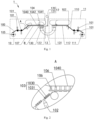
Fig. 2 is a partial enlarged view of portion A inFig. 1 ; -
Fig. 3 is a partial enlarged view of portion B inFig. 1 ; -
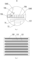
Fig. 4 is a schematic structure view of a stacked product of the stacking system provided by the second embodiment of the present application. - 1- stacking system; 10- positive pole piece cutting-conveying apparatus; 100- positive pole piece strip; 101- defect detection mechanism; 102- cutting tool; 103- clamping plate assembly; 1030-first clamping plate; 1031- second clamping plate; 104- annular infeed track; 1040- infeed segment; 1041- return segment; 1042- rejection segment; 105- positive pole piece unwinding mechanism; 106- conveying trolley; 107- positive pole piece; 11- negative pole piece cutting-conveying apparatus; 110- negative pole piece strip; 111- negative pole piece unwinding mechanism; 112-negative pole piece; 12- diaphragm unwinding mechanism; 120- unwinding roller; 121- pulling roller; 122- diaphragm; 13- stacking track; 130- first climbing segment; 131- second climbing segment; 14- stacking mechanism.
- Technical solutions of the present application will be clearly and completely described below in conjunction with the accompanying drawings; the described embodiments are apparently parts rather than all of the embodiments of the present application. All other embodiments that obtained by those of ordinary skill in the art based on the embodiments of the present application without any creative effort are also within the scope of the present application.
- It should be noted that the orientations or positional relationships indicated by the terms such as "central", "upper", "lower", "left", "right", "vertical", "horizontal", "inner", "outer" and the like are based on the orientations or positional relationships shown in the drawings, they are only intended for ease of description of the present application and simplicity of description rather than indicate or imply that the mentioned apparatuses or elements must have the particular orientations as well as being configured and operated in the particular orientations, and thus should not be construed as limiting of the present application. In addition, the terms "first", "second" and "third" are for the purpose of description only and should not be regarded as an indication or implication of relative importance.
- In the description of the present application, it should also be noted that the terms "installed", "joined" and "connected" should be construed broadly unless otherwise specified or defined; for example, they may be construed as fixedly connected, detachably connected or integrally connected; mechanically connected or electrically connected; directly joined or joined with an intermediate media or joined by interiors of two elements. Those of ordinary skill in the art may understand the particular meanings of the above terms in the present application based on the particular circumstances.
- With reference to
Figs. 1-4 , an embodiment of the present application provides a pole piece cutting-conveying apparatus which comprises a pole piece unwinding mechanism, a pole piece cutting mechanism and a pole piece conveying mechanism arranged in sequence, wherein "arranged in sequence" means sequentially arranging along an unwinding direction, i.e., the direction in which a pole piece strip is delivered, such that the pole piece strip unwound by the pole piece unwinding mechanism is delivered first to the pole piece cutting mechanism and then to the pole piece conveying mechanism. - The pole piece cutting mechanism is configured to perform a cutting process of the pole piece strip unwound by the pole piece unwinding mechanism to obtain pole pieces. Wherein the pole piece unwinding mechanism may adopt existing devices having pole piece unwinding function, for example, the pole piece unwinding mechanism may comprise a discharge roller and a driving roller and the discharge roller is conventionally made of steel, having a 3-9 inches outer diameter as well as an inflatable and tightening function, one end is fixed to a vertically arranged device large plate and another end is suspended or being supported by a moveable or fixed support; one end of the pole piece strip to be unwound is wrapped around the discharge roller and another end thereof is a free end which is intended to be frictional connected with the driving roller to drive the pole pieces by friction and pull out the strip from the discharge roller by cooperating with an active rotation of the discharge roller, the coefficient of friction between the driving roller and the pole pieces is 0.1 to 0.8, and the unwinding linear speed is 5-100 m/min. Further, the pole piece cutting mechanism is able to cut the free end of the pole piece strip segment by segment based on predetermined sizes, such that the pole piece strip is cut into pole pieces while being delivered toward the pole piece cutting mechanism with a cutting efficiency of 80-400 pieces/min and a 60-600 mm length for each cut pole piece.
- The pole piece conveying mechanism comprises an annular infeed
track 104 and a plurality ofconveying trolleys 106. Wherein, optionally, the number ofconveying trolleys 106 is ten-sixteen, the annular infeedtrack 104 comprises a linear track portion and an arc-shaped track portion, and the arc-shaped track portion has a diameter of 50-300 mm and the linear track portion has a length of 3-10 m. - The
annular infeed track 104 comprises aninfeed segment 1040 and areturn segment 1041 which are attached to one another end-to-end, and the end-to-end-attached positions of theinfeed segment 1040 and thereturn segment 1041 respectively act as an infeed station and an outfeed station. - The plurality of conveying
trolleys 106 are able to pick up the pole pieces at the infeed station and move from the infeed station to the outfeed station through theinfeed segment 1040, such that the plurality of conveyingtrolleys 106 are able to carry the pole pieces from the infeed station to the outfeed station through theinfeed segment 1040. - The plurality of conveying
trolleys 106 are able to release the pole pieces at the outfeed station to carry out the stacking process. The conveyingtrolleys 106 become empty conveyingtrolleys 106 after the pole pieces are released, i.e., become empty conveyingtrolleys 106 at the outfeed station. - The plurality of conveying
trolleys 106 are able to move from the outfeed station to the infeed station through thereturn segment 1041, such that the controlled conveyingtrolleys 106 are returned from the outfeed station to the infeed station through thereturn segment 1041 for picking up new cut pole pieces. The cycle repeats, so as to continuously and stably pick up, convey and release the pole pieces. - Optionally, the pole piece conveying mechanism further comprises an infeed roller which is spaced apart from the infeed station to form an infeed opening therebetween, said infeed roller is able to drive the pole pieces into the infeed opening to increase success rate of picking up the pole pieces by the conveying
trolleys 106. - Optionally, the
infeed segment 1040 has a linear shape and thereturn segment 1041 has a C-shape to reduce difficulty of turning of the conveyingtrolleys 106 and thus improve efficiency of the conveyingtrolleys 106 returning from the outfeed station to the infeed station. - In this embodiment, the conveying
trolleys 106 each comprises a pick-up plate and a pick-up driving member. The pick-up plate is formed with a positioning recess matching with a pole piece to confine the pole piece inside the positioning recess; the pick-up driving member acts inside the positioning recess to enable pick-up of the pole piece for example according to the principle of electrostatic adsorption or vacuum adsorption. - Optionally, the plurality of conveying
trolleys 106 are arranged on theannular infeed track 104 in a magnetic levitation manner, such that it is possible to improve start-stop accuracy and speed regulation accuracy of the conveyingtrolleys 106. - In an optional solution of this embodiment, the pole piece cutting-conveying apparatus further comprises
defect detection mechanisms 101, which are arranged between the pole piece cutting mechanism and the pole piece unwinding mechanism for detecting surface quality of the pole piece strip to determine whether the surface qualities of the pole pieces delivered to the pole piece conveying mechanism are acceptable. Wherein the surface qualities of the pole piece strip may be determined by the occurrence of white spots, material dropping or foil leakage and the like on the surface. - In addition, as shown in
Fig. 1 , thedefect detection mechanisms 101 may be the devices having surface defect detection function in prior arts, for example thedefect detection mechanisms 101 may carry out image detection for both side faces of the pole piece strip by means of linear array cameras or plane array cameras. - In this embodiment, in order to avoid the phenomenon that the pole piece strip becomes deviated in the pole piece unwinding mechanism during the unwinding process and thus avoid deflection of the pole pieces at the release position of the outfeed station, a deviation correction mechanism is arranged between the pole piece cutting mechanism and the pole piece unwinding mechanism so as to detect unwinding trajectory deviation of the pole piece strip. Wherein the deviation correction mechanism may adopt existing devices having deviation correction function, for example, the deviation correction mechanism may comprise a position sensor configured to detect the position of an edge of the pole piece strip to determine, based on the detection result of the position sensor, whether a left-side or right-side deviation of the pole piece strip is occurred.
- The deviation correction mechanism is electrically connected to the pole piece unwinding mechanism to adjust position of the pole piece unwinding mechanism according to the unwinding trajectory deviation. Specifically, if the pole piece strip has a right-side deviation, the pole piece unwinding mechanism is moved to the left; if the pole piece strip has a left-side deviation, the pole piece unwinding mechanism is moved to the right, therefore achieve the purpose of correct the deviation of the position of the pole piece strip.
- Optionally, to ensure the timeliness of the deviation correction of the pole piece strip carried out by the deviation correction mechanism, the deviation correction mechanism is arranged close to the pole piece unwinding mechanism in relation to the pole piece cutting mechanism.
- In the optional solution of the present application, a rejection of the pole pieces whose surface qualities are unacceptable is required in order to avoid mixing up of the unacceptable pole pieces with the acceptable pole pieces, so as to ensure that the surface qualities of all of the pole pieces released at the outfeed station are acceptable. Therefore, the
annular infeed track 104 further comprises arejection segment 1042 both ends of which are attached to the middle of theinfeed segment 1040 and the middle of thereturn segment 1041, respectively, such that the conveyingtrolleys 106 are able to move back to the middle of thereturn segment 1041 from the middle of theinfeed segment 1040 directly through therejection segment 1042. - It should be noted that the middle of the
infeed segment 1040 and the middle of thereturn segment 1041 are not necessarily the absolute midpoints of the two along their length directions, but some points on theinfeed segment 1040 and thereturn segment 1041 between the infeed station and the outfeed station, specific locations of which may be selected and adjusted based on actual needs. - The
defect detection mechanisms 101 are electrically connected to the conveyingtrolleys 106, that is to say, thedefect detection mechanisms 101 are able to communicate with the conveyingtrolleys 106 in a direct or indirect way as well as a wired or wireless way to determine whether the surface qualities of the pole pieces carried by the conveyingtrolleys 106 are acceptable, and thus provide a basis for the selection of the travel directions of the conveyingtrolleys 106 at the intersection of theinfeed segment 1040 and therejection segment 1042. - The conveying
trolleys 106 move the pole pieces to therejection segment 1042 and release them at this position when the qualities of the pole pieces carried thereon are determined unacceptable. Optionally, waste recovery mechanisms are arranged beside therejection segment 1042 to recover the rejected pole pieces released at therejection segment 1042 by the conveyingtrolleys 106, so as to facilitate centralized treatment of the rejected pole pieces. The waste recovery mechanisms may be waste recovery boxes or waste recovery cars and the like. - The conveying
trolleys 106 move the pole pieces over therejection segment 1042 to the outfeed station when the qualities of the pole pieces carried thereon are determined acceptable, so as to ensure that all the pole pieces delivered to the outfeed station are the ones having the acceptable surface qualities. - By arranging said
rejection segment 1042, it not only maintains the pole pieces at relative small conveying deviations without elongate their conveying distances, but also omits the need for adding a belt rejection mechanism and thus effectively reducing the size of the apparatus. Further, the fact that the rejection process could be done without elongate the conveying distances of the pole pieces effectively improves the conveying efficiency of the pole pieces. - In the optional solution of the present application, in order to improve the cutting efficiency and the delivery efficiency of the pole pieces into the infeed opening, the pole piece cutting mechanism comprises a clamping
plate assembly 103 and acutting tool 102, thecutting tool 102 may optionally be a metal cutting tool, a ceramics cutting tool, a laser cutting tool and the like, which is not limited herein. - The clamping
plate assembly 103 comprises afirst clamping plate 1030 and asecond clamping plate 1031 which are oppositely spaced apart, thefirst clamping plate 1030 and thesecond clamping plate 1031 are moveable toward and away from each other so as to grip and release the free end of the pole piece strip, specifically, thefirst clamping plate 1030 and thesecond clamping plate 1031 are respectively arranged to face opposite side faces of the pole piece strip. - The
cutting tool 102 is arranged on a side of the clampingplate assembly 103 which is close to the pole piece unwinding mechanism, so as to cut the free end of the pole piece strip during the gripping of the pole piece strip carried out by the clampingplate assembly 103 to obtain the pole pieces. As a result, the clamping and positioning action on the pole piece strip provided by the clampingplate assembly 103 is able to improve the stability of thecutting tool 102 when applying cutting force, an thus improve cutting accuracy of the pole pieces. - The clamping
plate assembly 103 is configured to be able to reciprocally move along the delivery direction of the pole piece strip so as to release the pole pieces when the pole piece strip is cut and move toward the pole piece unwinding mechanism as well as grip the uncut pole piece strip and pull it toward the infeed station, and by repeatedly doing so cutting of the pole pieces can be carried out continuously by means of the cooperation of the clampingplate assembly 103 and thecutting tool 102. - Optionally, the clamping
plate assembly 103 further comprises a mounting seat and a driving cylinder (not shown), the driving cylinder is joined to the mounting seat and is able to drive it to move reciprocally, and thefirst clamping plate 1030 and thesecond clamping plate 1031 are moveably connected to the mounting seat such that thefirst clamping plate 1030 and thesecond clamping plate 1031 are able to move toward and away from each other. - A second embodiment provides a stacking system which comprises the pole piece cutting-conveying apparatus in the first embodiment. The technical features of the pole piece cutting-conveying apparatus disclosed in the first embodiment are also applicable for this embodiment and thus will not be repeated herein.
- With reference to
Figs. 1-4 , in an optional solution of this embodiment, there are two pole piece cutting-conveying apparatuses, a positive pole piece cutting-conveyingapparatus 10 and a negative pole piece cutting-conveyingapparatus 11, respectively, wherein the positive pole piece cutting-conveyingapparatus 10 comprises a positive polepiece unwinding mechanism 105 which is configured for conveying a positivepole piece strip 100 such that it is cut by the pole piece cutting mechanism to obtainpositive pole pieces 107, and the negative pole piece cutting-conveyingapparatus 11 comprises a negative polepiece unwinding mechanism 111 which is configured for conveying a negativepole piece strip 110 such that it is cut by the pole piece cutting mechanism to obtainnegative pole pieces 112. - In this embodiment, the stacking
system 1 further comprises a stackingtrack 13 and a stackingmechanism 14. - Both ends of the stacking
track 13 are positioned below outfeed stations of said two pole piece cutting-conveying apparatuses, respectively, and the stackingmechanism 14 is able to reciprocally move between the outfeed stations of said two pole piece cutting-conveying apparatuses along the stackingtrack 13 such that said two pole piece cutting-conveying apparatuses alternately stack thepositive pole pieces 107 and thenegative pole pieces 112 onto the stackingmechanism 14 at the ends of the stackingtrack 13, so as to achieve alternating stacking of thepositive pole pieces 107 and thenegative pole pieces 112. - In this embodiment, the stacking
mechanism 14 comprises a stacking platform and a pressing plate. - At least one stacking station is provided on the stacking platform is moveably connected to the stacking
track 13 as well as reciprocally moveable between the outfeed stations of said two pole piece cutting-conveying apparatuses along the stackingtrack 13, all of the stacking stations are corresponded to the conveyingtrolleys 106 of the outfeed stations one by one when the stacking platform is moved to an end of the stackingtrack 13 so as to place the pole pieces released by the conveyingtrolleys 106 on all of the stacking stations one by one correspondingly. Wherein simultaneous stacking of multiple sets of pole pieces can be achieved when there are multiple stacking stations, so as to further improve stacking efficiency. - The pressing plate is moveably connected to the stacking platform so as to get out of the way of the pole pieces when they are released by the conveying
trolleys 106 and move to pressing the pole pieces toward the stacking platform after they are placed on the stacking stations, it is possible to keep the stacked pole pieces in place with the aid of the pressing plate to avoid shift, deformation or collapse of the stacked pole pieces during the reciprocal movement of the stacking platform, with a benefit of improving stacking accuracy. - Optionally, the pressing plate is moveably connected to the stacking platform. More specifically, the pressing plate is liftably or telescopically arranged to the stacking platform.
- In this embodiment, each end of the stacking
track 13 forms a climbing segment extending along an up-down direction, such that the conveyingtrolleys 106 stack the pole pieces to the stackingmechanism 14 at the climbing segments. More specifically, afirst climbing segment 130 is formed by an end of the stackingtrack 13 corresponding to the positive pole piece cutting-conveyingapparatus 10 and asecond climbing segment 131 is formed by an end of the stackingtrack 13 corresponding to the negative pole piece cutting-conveyingapparatus 11, the distance between an upper end and a lower end of each of thefirst climbing segment 130 and thesecond climbing segment 131 is not less than a target stacking thickness to ensure that a next layer of pole piece can always be continuously stacked on top of the stacked parts after each stay of the stacking platform at thefirst climbing segment 130 and thesecond climbing segment 131. - In this embodiment, a
diaphragm unwinding mechanism 12 comprises an unwinding roller 120 and a pullingroller 121, said unwinding roller 120 and said pullingroller 121 are configured to stretch and draw adiaphragm 122. - The unwinding roller 120 is positioned above said two pole piece cutting-conveying apparatuses and the pulling
roller 121 is positioned between said two pole piece cutting-conveying apparatuses, so as to ensure that there is no spatial interference between thediaphragm 122 and said two pole piece cutting-conveying apparatuses when thediaphragm 122 is reciprocally moved with the stacking platform. - Optionally, said stacking system further comprises existing post-processing devices such as gluing mechanism, heat pressing mechanism, weighing and inspecting mechanism and unloading mechanism and the like, wherein the stacked products which having unacceptable weights can be rejected in the unloading mechanism.
- As mentioned above, stacking steps of said stacking system are as follow.
- Cut and convey the
positive pole pieces 107 by means of the positive pole piece cutting-conveyingapparatus 10 and cut and convey thenegative pole pieces 112 by means of the negative pole piece cutting-conveyingapparatus 11. - Carry the
positive pole pieces 107 by means of at least one conveyingtrolley 106 at the outfeed station of the positive pole piece cutting-conveyingapparatus 10, move the stacking platform to thefirst climbing segment 130 along the stackingtrack 13 and make it stay at a position on thefirst climbing segment 130 in which the pressing plate is leveled with thepositive pole pieces 107 carried by the at least one conveyingtrolley 106, at the same time correspond the positions of the at least one conveyingtrolley 106 to at least one stacking station of the stacking platform one by one, respectively. - Move away the pressing plate to cover the
diaphragm 122 above the pressing plate on top of the previous layer ofnegative pole piece 112, expose top portions of all of the stacked parts at all of the stacking stations toward the conveyingtrolleys 106, and release thepositive pole pieces 107 by at least one conveyingtrolley 106 to accurately stack at least onepositive pole piece 107 on at least one stacking station one-to-one, then press and position all of the stacked parts at all of the stacking stations by means of the pressing plate. - As such, the stacking of one layer of
positive pole piece 107 is completed, the stacking platform then moves to thesecond climbing segment 131 along the stackingtrack 13, during which thediaphragm 122 is pulled and in the meantime covering top of the pressing plate. The pressing plate then moves away in order to cover top of the previous layer ofpositive pole piece 107 with thediaphragm 122 and then conduct the stacking process of a next layer ofnegative pole piece 112. As such, this layer ofnegative pole piece 112 is separated from the previous layer ofpositive pole piece 107 by thediaphragm 122, specific stacking steps of this layer ofnegative pole piece 112 are identical to that of the previous layer ofpositive pole piece 107 and thus will not be repeated herein. - After finish the stacking process of this layer of
negative pole piece 112, the stacking platform moves back to thefirst climbing segment 130 along the stackingtrack 13 to carry out stacking operation of a next layer ofpositive pole piece 107. The cycle repeats until finish the stacking process to obtain multiple sets of stacked products, i.e., cells. - After complete stacking, each stacking station is placed with a set of stacked products, and any layers of diaphragms of all of the stacked products are connected together. In order to separate multiple sets of stacked products, the diaphragms between adjacent stacking stations, i.e., adjacent stacked products may be cut to obtain multiple sets of independent stacked products.
- During the above-mentioned stacking process, as shown in
Figure 4 , if there is no strict requirement for stacking efficiency, only one set of pole pieces may be stacked on the stacking platform at a time. In the case that stacking multiple sets of pole pieces on the stacking platform at the same time, it is not only possible to simultaneously stacking multiple pole pieces but also improve the stacking efficiency. In addition, each pole piece is released, dropped and positioned directly towards each corresponding stacking station, during which there is no need for any conveying manipulator and positioning platform, no poor positioning occurs, less pole piece conveying deviation, higher alignment for each stacking station, and both of the apparatus's availability and stacking yield are significantly improved. - The stacking system in this embodiment has the same advantages as the pole piece cutting-conveying apparatus in the first embodiment, which will not be repeated herein.
- Finally, it should be noted that the above embodiments are intended for illustration of the technical solutions of the present application only, rather than limiting the same; although the present application has been described in detail with reference to the foregoing embodiments, those of ordinary skill in the art should understand that it is still possible to modify the technical solutions recorded in the foregoing embodiments, or to equivalently replace some or all of the technical features therein; these modifications or replacements will not cause the essence of the corresponding technical solutions to depart from the scope of the technical solutions of the embodiments of the present application. Furthermore, those skilled in the art will understand that although some embodiments described herein include certain features included in other embodiments rather than other features, combinations of the features of different embodiments are meant to be within the scope of the present application and form different embodiments. For example, any of the claimed embodiments may be used in any combination. The information disclosed in the Background section is merely intended to enhance the understanding of the general background of the present application and should not be construed as an admission of or in any way implying that the information constitutes the prior art that is already known to those skilled in the art.
- As mentioned above, the present disclosure provides a pole piece cutting-conveying apparatus and a stacking system. The present disclosure conveys a plurality of pole pieces by determined tracks by means of a plurality of conveying trolleys on a one-to-one basis, enabling high conveying efficiency, a fixed-point release with high pole piece release position accuracy, short conveying process, less accumulated deviation and high rotation accuracy, such that the stacking system to which said pole piece cutting-conveying apparatus is applied has extremely high stacking efficiency and stacking accuracy, so as to efficiently and accurately carry out cutting, conveying and stacking.
Claims (10)
- A pole piece cutting-conveying apparatus, characterized in that, it comprises a pole piece unwinding mechanism, a pole piece cutting mechanism and a pole piece conveying mechanism which are arranged in sequence;the pole piece cutting mechanism is configured to perform a cutting process of a pole piece strip unwound by the pole piece unwinding mechanism to obtain pole pieces;the pole piece conveying mechanism comprises an annular infeed track and a plurality of conveying trolleys;the annular infeed track comprises an infeed segment and a return segment which are attached to one another end-to-end, the end-to-end-attached positions of the infeed segment and the return segment respectively act as an infeed station and a outfeed station, and the plurality of conveying trolleys are moveable from the infeed station to the outfeed station through the infeed segment as well as from the outfeed station to the infeed station through the return segment, such that each of the conveying trolleys is able to pick up a pole piece at the infeed station and release it at the outfeed station.
- The pole piece cutting-conveying apparatus according to claim 1, characterized in that, it further comprises defect detection mechanisms, which are arranged between the pole piece cutting mechanism and the pole piece unwinding mechanism for detecting surface quality of the pole piece strip;the annular infeed track further comprises a rejection segment both ends of which are attached to the middle of the infeed segment and the middle of the return segment, respectively;the defect detection mechanisms are electrically connected to the conveying trolleys to determine whether the surface qualities of the pole pieces carried by the conveying trolleys are acceptable;the conveying trolleys move the pole pieces to the rejection segment and release them at this position when the qualities of the pole pieces carried thereon are determined unacceptable;the conveying trolleys move the pole pieces to the outfeed station when the qualities of the pole pieces carried thereon are determined acceptable.
- The pole piece cutting-conveying apparatus according to claim 2, characterized in that, the pole piece cutting mechanism comprises a clamping plate assembly and a cutting tool;the clamping plate assembly comprises a first clamping plate and a second clamping plate which are oppositely spaced apart, the first clamping plate and the second clamping plate are moveable toward and away from each other so as to grip and release a free end of the pole piece strip;the cutting tool is arranged on a side of the clamping plate assembly which is close to the pole piece unwinding mechanism, so as to cut the pole piece strip during the gripping of the pole piece strip carried out by the clamping plate assembly to obtain the pole pieces;the clamping plate assembly is configured to be able to reciprocally move along a delivery direction of the pole piece strip so as to release the pole pieces when the pole piece strip is cut and move toward the pole piece unwinding mechanism as well as grip the uncut pole piece strip and pull it toward the infeed station.
- The pole piece cutting-conveying apparatus according to any one of the claims 1 to 3, characterized in that, it further comprises a deviation correction mechanism which is arranged between the pole piece cutting mechanism and the pole piece unwinding mechanism for detecting unwinding trajectory deviation of the pole piece strip;
the deviation correction mechanism is electrically connected to the pole piece unwinding mechanism to adjust position of the pole piece unwinding mechanism according to the unwinding trajectory deviation. - The pole piece cutting-conveying apparatus according to any one of the claims 1 to 3, characterized in that, the plurality of conveying trolleys are arranged on the annular infeed track in a magnetic levitation manner, and/or
the pole piece conveying mechanism further comprises an infeed roller which is spaced apart from the infeed station to form an infeed opening therebetween, said infeed roller is able to drive the pole pieces into the infeed opening. - A stacking system characterized by comprising the pole piece cutting-conveying apparatus according to any one of the claims 1 to 5.
- The stacking system according to claim 6, characterized in that,there are two pole piece cutting-conveying apparatuses which are configured to convey positive pole pieces and negative pole pieces, respectively;the stacking system further comprises a stacking track and a stacking mechanism;both ends of the stacking track are positioned below outfeed stations of said two pole piece cutting-conveying apparatuses, respectively, and the stacking mechanism is able to reciprocally move between the outfeed stations of said two pole piece cutting-conveying apparatuses along the stacking track such that said two pole piece cutting-conveying apparatuses alternately stack the positive pole pieces and the negative pole pieces onto the stacking mechanism at the ends of the stacking track.
- The stacking system according to claim 7, characterized in that, the stacking mechanism comprises a stacking platform and a pressing plate;at least one stacking station is provided on the stacking platform and all of the stacking stations are corresponded to the conveying trolleys of the outfeed stations one by one when the stacking platform is moved to an end of the stacking track so as to place the pole pieces released by the conveying trolleys on all of the stacking stations one by one correspondingly;the pressing plate and the stacking platform are moveably connected so as to get out of the way of the pole pieces when they are released by the conveying trolleys and move to pressing the pole pieces toward the stacking platform after they are placed on the stacking stations.
- The stacking system according to claim 7, characterized in that, both ends of the stacking track each forms a climbing segment extending along an up-down direction, such that the conveying trolleys stack the pole pieces to the stacking mechanism at the climbing segments;
the distance between an upper end and a lower end of each of the climbing segments is not less than a target stacking thickness. - The stacking system according to claim 7, characterized by further comprising a diaphragm unwinding mechanism which comprises an unwinding roller and a pulling roller, said unwinding roller and said pulling roller are configured to stretch and draw a diaphragm;
the unwinding roller is positioned above said two pole piece cutting-conveying apparatuses and the pulling roller is positioned between said two pole piece cutting-conveying apparatuses.
Applications Claiming Priority (2)
| Application Number | Priority Date | Filing Date | Title |
|---|---|---|---|
| CN202111412120.9A CN114122528B (en) | 2021-11-25 | 2021-11-25 | Electrode Cutting Conveyor and Lamination System |
| PCT/CN2022/082513 WO2023092910A1 (en) | 2021-11-25 | 2022-03-23 | Pole piece cutting and conveying device and lamination system |
Publications (3)
| Publication Number | Publication Date |
|---|---|
| EP4439770A1 true EP4439770A1 (en) | 2024-10-02 |
| EP4439770A8 EP4439770A8 (en) | 2024-11-06 |
| EP4439770A4 EP4439770A4 (en) | 2025-08-27 |
Family
ID=80373088
Family Applications (1)
| Application Number | Title | Priority Date | Filing Date |
|---|---|---|---|
| EP22897011.7A Pending EP4439770A4 (en) | 2021-11-25 | 2022-03-23 | Device for cutting and conveying pile pieces and lamination system |
Country Status (3)
| Country | Link |
|---|---|
| EP (1) | EP4439770A4 (en) |
| CN (1) | CN114122528B (en) |
| WO (1) | WO2023092910A1 (en) |
Families Citing this family (13)
| Publication number | Priority date | Publication date | Assignee | Title |
|---|---|---|---|---|
| CN114122528B (en) * | 2021-11-25 | 2023-07-21 | 蜂巢能源科技有限公司 | Electrode Cutting Conveyor and Lamination System |
| WO2023193217A1 (en) * | 2022-04-08 | 2023-10-12 | 宁德时代新能源科技股份有限公司 | Marking processing method and apparatus for continuous composite material belt, and computer device |
| CN114803628B (en) * | 2022-04-18 | 2024-09-20 | 上海兰钧新能源科技有限公司 | A pole piece feeding device and method |
| CN115051040A (en) * | 2022-05-31 | 2022-09-13 | 深圳市兴禾自动化股份有限公司 | Pole piece compounding device and compounding process thereof |
| CN115000488B (en) * | 2022-08-02 | 2022-11-18 | 江苏中关村嘉拓新能源设备有限公司 | Sheet inserting device and method for lamination equipment |
| CN115635198B (en) * | 2022-09-08 | 2025-06-10 | 三一技术装备有限公司 | Laser cutting method and laser cutting device for pole piece material belt |
| CN116404096B (en) * | 2023-03-09 | 2024-10-08 | 三一技术装备有限公司 | Film-making method and system |
| CN116864776B (en) * | 2023-08-02 | 2025-03-28 | 三一技术装备有限公司 | Lamination device and battery production line |
| CN117589803B (en) * | 2023-11-20 | 2024-07-26 | 深圳市日联科技有限公司 | Laminated battery detection system and method |
| CN117977008A (en) * | 2023-12-08 | 2024-05-03 | 海目星激光科技集团股份有限公司 | Lamination process and cutting and lamination machine |
| CN117712452B (en) * | 2023-12-22 | 2024-07-30 | 三一技术装备有限公司 | Sheet making device, sheet stacking device and battery production line |
| CN118710870B (en) * | 2024-05-15 | 2025-03-25 | 钛玛科(北京)工业科技有限公司 | Detection method, device, electronic equipment and medium for positive electrode sheet of square battery cell |
| CN121551335B (en) * | 2026-01-26 | 2026-03-31 | 速博达(深圳)自动化有限公司 | Pole piece processing system and method |
Family Cites Families (24)
| Publication number | Priority date | Publication date | Assignee | Title |
|---|---|---|---|---|
| DE102017215905A1 (en) * | 2017-09-08 | 2019-03-14 | OPTIMA life science GmbH | Method and device for producing an electrode stack |
| DE102017216213A1 (en) * | 2017-09-13 | 2019-03-14 | Robert Bosch Gmbh | Process for producing an electrode stack |
| CN208014839U (en) * | 2018-02-28 | 2018-10-26 | 深圳市格林晟科技有限公司 | A kind of Full-automatic lithium battery battery cuts folding integrated machine |
| CN110642001A (en) * | 2018-06-26 | 2020-01-03 | 苏州瀚川智能科技股份有限公司 | Circulation feeding mechanism |
| CN109390635B (en) * | 2018-09-30 | 2020-08-14 | 合肥国轩高科动力能源有限公司 | An automatic lamination mechanism for Z-type lamination cells |
| CN209312946U (en) * | 2018-11-22 | 2019-08-27 | 中信国安盟固利动力科技有限公司 | A kind of lithium ion battery brush dust punching inspection piece and lamination all-in-one machine |
| CN109533957B (en) * | 2018-11-26 | 2020-06-12 | 合肥国轩高科动力能源有限公司 | Battery positive and negative pole piece transfer mechanism |
| CN209912982U (en) * | 2019-05-20 | 2020-01-07 | 深圳吉阳智能科技有限公司 | Cutting and folding integrated machine |
| CN110190337B (en) * | 2019-05-20 | 2024-04-09 | 深圳吉阳智能科技有限公司 | Cutting and stacking integrated machine |
| CN210136959U (en) * | 2019-07-05 | 2020-03-10 | 哈工大机器人(中山)无人装备与人工智能研究院 | Cross cutting lamination all-in-one |
| CN110364766B (en) * | 2019-07-16 | 2022-06-21 | 蜂巢能源科技有限公司 | Die cutting lamination system and method |
| CN110391449A (en) * | 2019-07-16 | 2019-10-29 | 蜂巢能源科技有限公司 | Die-cut lamination system and method |
| CN110380128B (en) * | 2019-07-16 | 2020-06-30 | 蜂巢能源科技有限公司 | Die-cut lamination system and method |
| CN110404797A (en) * | 2019-07-29 | 2019-11-05 | 上海电气集团股份有限公司 | A kind of transportation resources of lithium battery pole slice and transportation system |
| CN210296541U (en) * | 2019-07-31 | 2020-04-10 | 广东利元亨智能装备股份有限公司 | Pole piece deviation rectifying module |
| CN210668543U (en) * | 2019-10-09 | 2020-06-02 | 无锡先导智能装备股份有限公司 | Battery core lamination equipment and multi-station battery core lamination equipment |
| CN111477939A (en) * | 2020-05-26 | 2020-07-31 | 苏州凌威新能源科技有限公司 | Lamination device |
| CN212768617U (en) * | 2020-07-22 | 2021-03-23 | 无锡先导智能装备股份有限公司 | Conveying device and lamination equipment |
| CN112635846A (en) * | 2020-12-31 | 2021-04-09 | 深圳市诚捷智能装备股份有限公司 | Cross cutting lamination all-in-one |
| CN112768744B (en) * | 2021-01-21 | 2022-10-04 | 深圳市科瑞新能源装备技术有限公司 | Battery manufacturing apparatus |
| CN214477590U (en) * | 2021-02-09 | 2021-10-22 | 无锡先导智能装备股份有限公司 | Composite device and lamination machine |
| CN214797510U (en) * | 2021-04-08 | 2021-11-19 | 浙江凯乐士科技集团股份有限公司 | Lamination production line system of battery pole piece |
| CN112968220A (en) * | 2021-04-08 | 2021-06-15 | 浙江凯乐士科技有限公司 | Lamination production line system of battery pole piece |
| CN114122528B (en) * | 2021-11-25 | 2023-07-21 | 蜂巢能源科技有限公司 | Electrode Cutting Conveyor and Lamination System |
-
2021
- 2021-11-25 CN CN202111412120.9A patent/CN114122528B/en active Active
-
2022
- 2022-03-23 WO PCT/CN2022/082513 patent/WO2023092910A1/en not_active Ceased
- 2022-03-23 EP EP22897011.7A patent/EP4439770A4/en active Pending
Also Published As
| Publication number | Publication date |
|---|---|
| EP4439770A8 (en) | 2024-11-06 |
| CN114122528B (en) | 2023-07-21 |
| CN114122528A (en) | 2022-03-01 |
| EP4439770A4 (en) | 2025-08-27 |
| WO2023092910A1 (en) | 2023-06-01 |
Similar Documents
| Publication | Publication Date | Title |
|---|---|---|
| EP4439770A1 (en) | Pole piece cutting and conveying device and lamination system | |
| CN109230515B (en) | Automatic film sticking machine | |
| CN110247124B (en) | A high-speed lamination method for lithium-ion batteries, a lamination device and a lithium-ion battery | |
| KR101479724B1 (en) | System for producing electrodes of battery | |
| CN109158324B (en) | Automatic detection and sorting device | |
| KR20200026144A (en) | System for producing electrodes of battery | |
| CN204315681U (en) | Cell winding device | |
| EP2815997B1 (en) | Conveying device and conveying method | |
| CN108001962B (en) | Cell vertical conveyor, vertical cell coating machine and coating method thereof | |
| CN102385981B (en) | Transformer core manufacturing apparatus and method | |
| KR101296939B1 (en) | Laminating apparatus for electrode substrate | |
| CN107331885A (en) | A kind of battery core process equipment | |
| JP5893427B2 (en) | Belt-shaped battery material transport device and transport method | |
| CN109051565B (en) | Aerial shuttle | |
| KR101810143B1 (en) | Apparatus for pressing and slitting electrode of secondary battery | |
| US4578860A (en) | Apparatus for manufacturing iron core | |
| JP2013165025A (en) | Device and method for transferring belt-like cell material | |
| CN117226923B (en) | Processing equipment | |
| CN117766865A (en) | Cutting and stacking integrated equipment | |
| CN112768744B (en) | Battery manufacturing apparatus | |
| KR101264517B1 (en) | Laminating apparatus for electrode substrate | |
| CN217731901U (en) | Square lithium battery conveying device | |
| CN203941110U (en) | Battery pole ear defect detection equipment | |
| CN215008307U (en) | Battery manufacturing apparatus | |
| CN207810548U (en) | A kind of handling system for cylinder type lithium battery workshop |
Legal Events
| Date | Code | Title | Description |
|---|---|---|---|
| STAA | Information on the status of an ep patent application or granted ep patent |
Free format text: STATUS: THE INTERNATIONAL PUBLICATION HAS BEEN MADE |
|
| PUAI | Public reference made under article 153(3) epc to a published international application that has entered the european phase |
Free format text: ORIGINAL CODE: 0009012 |
|
| STAA | Information on the status of an ep patent application or granted ep patent |
Free format text: STATUS: REQUEST FOR EXAMINATION WAS MADE |
|
| 17P | Request for examination filed |
Effective date: 20240305 |
|
| AK | Designated contracting states |
Kind code of ref document: A1 Designated state(s): AL AT BE BG CH CY CZ DE DK EE ES FI FR GB GR HR HU IE IS IT LI LT LU LV MC MK MT NL NO PL PT RO RS SE SI SK SM TR |
|
| RIN1 | Information on inventor provided before grant (corrected) |
Inventor name: WANG, XUAN Inventor name: WANG, XUEFEI Inventor name: QIN, JIE Inventor name: XU, CHUNLONG Inventor name: YIN, DONGXING Inventor name: ZHAO, KAI |
|
| DAV | Request for validation of the european patent (deleted) | ||
| DAX | Request for extension of the european patent (deleted) | ||
| REG | Reference to a national code |
Ref country code: DE Ref legal event code: R079 Free format text: PREVIOUS MAIN CLASS: H01M0010058500 Ipc: H01M0010040000 |
|
| RIC1 | Information provided on ipc code assigned before grant |
Ipc: B65H 35/00 20060101ALI20250429BHEP Ipc: B65H 16/02 20060101ALI20250429BHEP Ipc: H01M 10/0525 20100101ALI20250429BHEP Ipc: H01M 10/0585 20100101ALI20250429BHEP Ipc: H01M 10/04 20060101AFI20250429BHEP |
|
| A4 | Supplementary search report drawn up and despatched |
Effective date: 20250728 |
|
| RIC1 | Information provided on ipc code assigned before grant |
Ipc: H01M 10/04 20060101AFI20250722BHEP Ipc: H01M 10/0585 20100101ALI20250722BHEP Ipc: H01M 10/0525 20100101ALI20250722BHEP Ipc: B65H 16/02 20060101ALI20250722BHEP Ipc: B65H 35/00 20060101ALI20250722BHEP |