EP4438510B1 - Schachtel zum verpacken von kuchen und feingebäck - Google Patents
Schachtel zum verpacken von kuchen und feingebäck Download PDFInfo
- Publication number
- EP4438510B1 EP4438510B1 EP23166025.9A EP23166025A EP4438510B1 EP 4438510 B1 EP4438510 B1 EP 4438510B1 EP 23166025 A EP23166025 A EP 23166025A EP 4438510 B1 EP4438510 B1 EP 4438510B1
- Authority
- EP
- European Patent Office
- Prior art keywords
- lip
- slit
- box
- front wall
- container portion
- Prior art date
- Legal status (The legal status is an assumption and is not a legal conclusion. Google has not performed a legal analysis and makes no representation as to the accuracy of the status listed.)
- Active
Links
Images

Classifications
-
- B—PERFORMING OPERATIONS; TRANSPORTING
- B65—CONVEYING; PACKING; STORING; HANDLING THIN OR FILAMENTARY MATERIAL
- B65D—CONTAINERS FOR STORAGE OR TRANSPORT OF ARTICLES OR MATERIALS, e.g. BAGS, BARRELS, BOTTLES, BOXES, CANS, CARTONS, CRATES, DRUMS, JARS, TANKS, HOPPERS, FORWARDING CONTAINERS; ACCESSORIES, CLOSURES, OR FITTINGS THEREFOR; PACKAGING ELEMENTS; PACKAGES
- B65D5/00—Rigid or semi-rigid containers of polygonal cross-section, e.g. boxes, cartons or trays, formed by folding or erecting one or more blanks made of paper
- B65D5/42—Details of containers or of foldable or erectable container blanks
- B65D5/64—Lids
- B65D5/66—Hinged lids
- B65D5/6626—Hinged lids formed by folding extensions of a side panel of a container body formed by erecting a "cross-like" blank
- B65D5/665—Hinged lids formed by folding extensions of a side panel of a container body formed by erecting a "cross-like" blank the lid being held in closed position by self-locking integral flaps or tabs
- B65D5/6661—Flaps provided over the total length of the lid edge opposite to the hinge
- B65D5/6664—Flaps provided over the total length of the lid edge opposite to the hinge combined with flaps or tabs provided at the side edges of the lid
- B65D5/6667—Flaps provided over the total length of the lid edge opposite to the hinge combined with flaps or tabs provided at the side edges of the lid and connected to one another in order to form an uninterrupted telescoping flange
-
- B—PERFORMING OPERATIONS; TRANSPORTING
- B65—CONVEYING; PACKING; STORING; HANDLING THIN OR FILAMENTARY MATERIAL
- B65D—CONTAINERS FOR STORAGE OR TRANSPORT OF ARTICLES OR MATERIALS, e.g. BAGS, BARRELS, BOTTLES, BOXES, CANS, CARTONS, CRATES, DRUMS, JARS, TANKS, HOPPERS, FORWARDING CONTAINERS; ACCESSORIES, CLOSURES, OR FITTINGS THEREFOR; PACKAGING ELEMENTS; PACKAGES
- B65D85/00—Containers, packaging elements or packages, specially adapted for particular articles or materials
- B65D85/30—Containers, packaging elements or packages, specially adapted for particular articles or materials for articles particularly sensitive to damage by shock or pressure
- B65D85/36—Containers, packaging elements or packages, specially adapted for particular articles or materials for articles particularly sensitive to damage by shock or pressure for bakery products, e.g. biscuits
Definitions
- the invention relates to a rectangular folding box primarily for packing cakes and pastries and usually produced from a foldable cardboard sheet.
- the invention is in particular related to the closure of a box of this type.
- Rectangular cardboard folding boxes for packing cakes are known in various types and sizes.
- One much-used type comprises a container part and a lid part, both the container and the lid being formed of cardboard panels.
- the box is made from a pre-cut sheet of cardboard that is pre-folded in a manner to enable the quick unfolding of the box so that it is directly ready for use.
- the container comprises a rectangular or square base panel for placing the cakes or pastries thereon, and four upstanding sidewall panels surrounding the base panel.
- the lid comprises a top panel of equal dimensions to the base panel and configured to be placed above and parallel to the base panel when the box is closed.
- the lid further comprises three sidewall panels and the lid is connected to one of the sidewall panels of the container via a fold line, so that when the box is closed, the three sidewalls of the lid overlap and lie against corresponding sidewalls of the container.
- the overlapping sidewalls have the same height, i.e. they overlap across the full height of the box.
- Boxes have therefore been designed which include a built-in closure that can be opened and closed multiple times without requiring any tools.
- patent publication document EP3061698 shows a box having the above-named characteristics, including the fully overlapping sidewalls of the lid and container.
- the front wall of the container is attached by a fold line to the base panel but not to the adjacent sidewalls of the container.
- the box is configured therefore to be closed by closing the lid onto the container with the front wall of the container folded down, i.e. lying flat on a table or other support surface.
- the box is secured by folding the front wall of the container upward until it lies against the front wall of the lid. Both these front walls are provided with cooperating securing means.
- the container wall is provided with a pushing lip comprising a gripping part and a lip part protruding from the gripping part and suitable for being inserted in an opening provided in the front wall of the lid. While this solution prevents the box from opening during most manipulations when closed for the first time, the pushing lip is not secured against slipping out of the opening when the gripping part is inadvertently pivoted forward. Also, the gripping part needs to be pivoted quite far before the lip part can be inserted or drawn out of the opening. As a consequence, the gripping part may not return fully to being coplanar with the front wall of the container and stick out from said front wall after multiple openings and closures, which increases the probability that the lip part is inadvertently pulled out of the opening.
- the box comprises a container portion and a lid portion, the container portion being formed of a base panel and four sidewalls, the lid portion being formed of a top panel and three sidewalls, with the top panel being pivotably attached to the rear wall of the container portion by a fold line.
- the front wall of the container portion is pivotable with respect to the base panel while not being attached to the side walls of the container portion, so that the lid can be closed with the container's front wall being pivoted downward.
- Said front wall of the container portion and the front wall of the lid portion are respectively provided with a foldable cut-out lip and a slit.
- the lip comprises tooth sections having tips which are configured to be inserted in the slit by a snap action enabled by the shape of the slit and the tooth sections and by the relative dimensions of the interlocking parts, thereby securing the closure of the box and preventing unwanted or accidental opening whilst still enabling the deliberate opening and re-closing of the box.
- the terms "one or more” or “at least one”, such as one or more or at least one member(s) of a group of members, is clear per se, by means of further exemplification, the term encompasses inter alia a reference to any one of said members, or to any two or more of said members, such as, e.g., any ⁇ 3, ⁇ 4, ⁇ 5, ⁇ 6 or ⁇ 7 etc. of said members, and up to all said members.
- Figure 1 shows a folding box 1 according to an embodiment of the invention in the unfolded and opened state.
- the box comprises a container portion 2 and a lid portion 3.
- the container portion comprises a square base panel 4, a rear wall 5 and two sidewalls 6, and a front wall 7 that is connected only to the base panel 4 by a fold line 8, and not to the sidewalls 6.
- the sidewalls 6 are formed of a short part 6a and a long part 6b which are cut out according to specific patterns and glued together in a manner to enable easy unfolding of the box.
- the shape of these patterns may be in accordance with known designs, and the shapes shown in the drawings are not limiting the scope of the present invention.
- the lid portion 3 comprises a top panel 15, a front wall 16 and two sidewalls 17.
- the sidewalls are formed of pre-folded panels and flaps 18 glued to these panels, again to enable easy unfolding in a manner known as such from existing designs.
- the characteristic features of the embodiment shown in Figure 1 are related to the closure of the box.
- the front wall 7 of the container portion 2 is provided with a lip 20 in the form of a foldable cut-out that is pivotable about a fold line 21.
- the front wall 16 of the lid portion 3 comprises a slit 22 positioned so that the lip 20 is insertable in the slit 22.
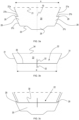
- FIGs 2a to 2d illustrate the closing sequence : after placing a cake or pastries (not shown) on the base panel 4 with the box 1 placed on a table or other support surface, the lid portion 3 is pivoted towards the container portion 2, while the container portion's front wall 7 is pivoted downward about fold line 8, said front wall 7 either lying flat on the table or pivoted slightly upward due to the stiffness of the fold line 8, as shown in Figure 2a .
- the lid portion 3 is in the closed position, the sidewalls 17 of the lid portion are overlapping the sidewalls 6 of the container portion on the outside thereof, as shown in Figure 2b , and the top panel 15 is essentially parallel to the base panel 4.
- the front wall 7 of the container portion is pivoted upwards manually, as shown in Figure 2c .
- the lip 20 is manually pushed inward as the front wall 7 of the container portion approaches the front wall 16 of the lid portion.
- the lip 20 is inserted into the slit 22, thereby securing the box, as shown in Figure 2d .
- FIG. 3a shows the shape of the lip 20 in detail.
- the fold line 21 forms the rear edge of the lip 20.
- the fold line 21 is preferably a pre-folded fold line or a connection comprising multiple aligned incisions which facilitate the pivoting of the lip 20 about fold line 21 out of the face of the front wall 7.
- the front edge 25 of the lip comprises a central trapezoid-shaped protrusion 26.
- the side edges 27 are inclined towards each other, so that the lip 20 becomes narrower from the fold line 21 toward the front edge 25.
- Each side edge 27 comprises an inclined base part 27a, a step 27b and an inclined top part 27c.
- the step 27b is preferably parallel to the fold line 21.
- the step 27b and the inclined top part 27c can thus be regarded as forming a tooth section 28, extending laterally outward with respect to the base part 27a of each side edge 27.
- the tips 29 of the tooth sections 28 are defined as the intersections between the steps 27b and the inclined top part 27c of the edges 27.
- the tooth sections 28 are equal in size and shape and symmetrically placed with respect to centre line 19 of the lip 20.
- the slit 22 comprises a flat part 30 and two upwardly inclined lateral parts 31 ('upwardly' meaning towards the top edge of the lip portion's front wall 16).
- the lateral parts 31 are of equal length and inclined at equal oblique angles with respect the flat part 30.
- the slit 22 further comprises two centrally placed incisions 32 arranged symmetrically with respect to each other on either side of the flat part 30 and oriented perpendicularly with respect to said flat part 30. Because of the inclined lateral parts 31, the slit 22 forms a cut-out 33 in the lid's front wall 16.
- the cut-out 33 is delimited by the flat slit part 30, the inclined slit parts 31 and a bend line 34.
- the bend line 34 is represented as a thin dotted line which is only a representation intended to indicate the line's position. In reality, this line is not visible, i.e. it is not a pre-defined fold line like line 21.
- the length and orientation of the inclined parts 31 is such that the cut-out 33 has sufficient stiffness so that it can be bent essentially elastically about bend line 34 during closing and securing of the box. In other words, the cut-out 33 bends out of the plane of the wall 16 when pushed inward during closure of the box and essentially returns to its in-plane position when the bending force is removed.
- the length of the incisions 32 is preferably lower than the height of the cut-out 33 (i.e. the distance between the lines 34 and 30).
- the protrusion 26 When inserting the lip 20 into the slit 22, the protrusion 26 enters first, thereby slightly bending the cut-out 33 backwards. At this point, the lip 20 is manually pivoted out of the plane of the wall 7, as illustrated in Figure 2c .
- the lip 20 and the slit 22 are preferably positioned with respect to each other so that the lip 20 is not perpendicular to the wall 7 at the moment of entry into the slit 22, but rather inclined downward relative to said wall 7.
- the incisions 32 facilitate the entry of the protrusion 26 without bending the cut-out 33 too much.
- the distance a between the tips 29 of the tooth sections 28 is slightly larger than the width w of the flat part 30 of the slit 22.
- the lip 20 is then pivoted back towards the in-plane condition, illustrated in the transparent view in Figure 3c , which shows the lip 20 as it is inserted in the slit 22 and pivoted back to the in-plane condition (parallel to the wall 7).
- this condition will not be reached 100% because the lip is now inserted into the slit, but the condition will in any case be approximated sufficiently closely to ensure that the box is securely closed while no parts are protruding excessively outward from the front of the closed box.
- the snap action ensures a more secured closure of the box compared to the prior art solutions and a better protection against unwanted or accidental opening of the box.
- This closure and securing system thereby allows multiple openings and closures of the box whilst prohibiting unwanted or accidental opening of the box when closed.
- the shape of the protrusion 26 may be different from the trapezoid shape shown in the drawings.
- This protrusion 26 could for example have a curved shape or a half-circle shape.
- the position of the tips 29 of the tooth portions 28 is shown to be more or less halfway along the side edges 27, but these tips 29 could be placed a bit closer or further away from this half-way position and still enable the above-described functionality.
- the incisions 32 are preferred but could be omitted if the material of the box enables the desired degree of elastic bending of the cut-out 33.
- Another alternative is to include only one of the incisions 32, i.e. an incision either above the flat part 30 of the slit or below the flat part 30 of the slit.
- the invention is equally related to a method for closing and opening a box according to the invention.
- the method for closing the box comprises the steps of :
- Opening the box takes place by the following steps :
- Both the closure and the opening is thereby done in two stages separated by the snap action, i.e. the tips 29 of the tooth sections 28 being forced into and out of the slit 22.
- the two-step closing action in particular allows the user to physically experience the securing of the box, so that inadequate closing is less likely to occur.
- the invention is equally related to a pre-cut sheet of a suitable material, preferably cardboard, configured to be pre-folded so as to form a folding box in accordance with the invention.
- a suitable material preferably cardboard
- the outward shape of the sheet can be in accordance with presently known designs.
- the sheet is characterized by the presence of a foldable lip 20 and a corresponding slit 22 according to any embodiment of the invention.
Landscapes
- Engineering & Computer Science (AREA)
- Mechanical Engineering (AREA)
- Cartons (AREA)
Claims (9)
- Faltschachtel (1) zum Verpacken von Nahrungsmitteln wie Kuchen, umfassend einen Behälterabschnitt (2) und einem Deckelabschnitt (3), wobei der Behälterabschnitt eine Bodenplatte (4) und vier Seitenwände, und zwar eine Rückwand (5), eine Vorderwand (7) und zwei Seitenwände (6), umfasst, wobei der Deckelabschnitt (3) eine Deckplatte (15) und drei Seitenwände, und zwar eine Vorderwand (16) und zwei Seitenwände (17), umfasst, wobei die Deckplatte (15) schwenkbar an einem oberen Rand der Rückwand (5) des Behälterabschnitts (2) angebracht ist, so dass der Deckelabschnitt (3) durch Schwenken des Deckelabschnitts nach vorne, bis die Deckplatte (15) im Wesentlichen parallel zu der Basisplatte (4) verläuft, geschlossen werden kann, und wobei:- die Vorderwand (7) des Behälterabschnitts (2) schwenkbar an der Bodenplatte (4) und nicht an den Seitenwänden (6) des Behälterabschnitts (2) angebracht ist,- die Vorderwände (7, 16) des Behälterabschnitts und des Deckelabschnitts jeweils mit einer Lippe (20) und einer Öffnung (22) versehen sind, wobei die Lippe zum Einführen in die Öffnung ausgestaltet ist, um die Schachtel nach dem Schließen des Deckelabschnitts (3) und dem Hochklappen der Vorderwand (7) des Behälterabschnitts (2) zu sichern,dadurch gekennzeichnet, dass:- die Lippe (20) ein faltbarer Ausschnitt der Vorderwand (7) des Behälterabschnitts ist und einen hinteren Rand, der durch eine Faltlinie (21) gebildet wird, die mit der Vorderwand (7) des Behälterabschnitts verbunden ist, zwei Seitenränder (27) und einen vorderen Rand (25) umfasst,- der vordere Rand (25) einen mittig angeordneten Vorsprung (26) umfasst,- die Seitenränder (27) zueinander geneigt und mit symmetrisch angeordneten Zahnabschnitten (28) versehen sind,- die Öffnung in der Vorderwand des Deckels ein Schlitz (22) ist, der einen flachen Abschnitt (30) und zwei nach oben geneigte Seitenabschnitte (31) umfasst, wobei der flache Abschnitt dazu ausgestaltet ist, zuerst den Vorsprung (26) der Lippe (20) darin aufzunehmen, wenn die Lippe in den Schlitz (22) eingeführt wird,- der Abstand (a) zwischen den Spitzen (29) der Zahnabschnitte etwas größer als die Länge (w) des flachen Abschnitts (30) des Schlitzes ist, so dass das fortgesetzte Einführen der Lippe (20) in den Schlitz (22) erfordert, dass ein Widerstand überwunden wird, indem die Spitzen der Zahnabschnitte an den Enden des flachen Abschnitts (30) des Schlitzes (22) vorbeigeschnappt werden.
- Schachtel (1) nach Anspruch 1, wobei der Schlitz (22) mindestens einen Einschnitt (32) umfasst, der senkrecht zu dem flachen Teil (30) des Schlitzes ausgerichtet und mittig zu dem flachen Teil (30) platziert ist.
- Schachtel (1) nach Anspruch 1, wobei der Schlitz (22) ferner zwei Einschnitte (32) gleicher Länge umfasst, der symmetrisch zu dem flachen Teil (30) des Schlitzes platziert und senkrecht zu dem flachen Teil (30) ausgerichtet sind.
- Schachtel (1) nach einem der vorhergehenden Ansprüche, wobei der Vorsprung (26) trapezförmig ist.
- Schachtel (1) nach einem der vorhergehenden Ansprüche, wobei die Spitzen (29) der Zahnabschnitte (28) etwa auf halber Strecke entlang der Länge der Seitenränder (27) der Lippe angeordnet sind.
- Schachtel (1) nach einem der vorhergehenden Ansprüche, wobei jeder der Seitenränder (27) der Lippe einen geneigten Basisabschnitt (27a), eine Stufe (27b) und einen geneigten oberen Abschnitt (27c) umfasst, der sich von dem Basisabschnitt (27c) nach außen erstreckt, so dass der Zahnabschnitt (28) durch die Stufe (27b) und den sich nach außen erstreckenden oberen Abschnitt (27c) gebildet wird.
- Verfahren zum Verschließen einer Schachtel (1) nach einem der vorhergehenden Ansprüche, wobei das Verfahren die folgenden Schritte umfasst:- Schwenken des Deckelabschnitts (3), bis die Seitenwände (17) des Deckelabschnitts die Seitenwände (6) des Behälterabschnitts (2) überlappen, während die Vorderwand (7) des Behälterabschnitts heruntergeklappt ist,- Hochklappen der Vorderwand (7) des Behälterabschnitts und Herausschwenken der Lippe (20) um die Faltlinie (21) aus der Position, in der sie auf gleicher Ebene liegt,- Einführen der Lippe (20) in den Schlitz (22), bis ein Widerstand spürbar ist,- Überwinden des Widerstands, wodurch die Lippe (20) in den Schlitz (22) eingeschnappt wird,- Zurückschwenken der Lippe (20) zu der Position auf gleicher Ebene hin.
- Verfahren zum Öffnen einer Schachtel (1) nach einem der Ansprüche 1 bis 6, wobei das Verfahren die folgenden Schritte umfasst:- Ziehen der Vorderwand (7) des Behälterabschnitts von der Vorderwand (16) des Deckelabschnitts weg, wodurch die Lippe (20) teilweise aus dem Schlitz (22) gezogen wird, bis ein Widerstand spürbar ist,- Überwinden des Widerstands und Herausziehen der Lippe (20) weiter aus dem Schlitz (22).
- Bogen, der zum Bilden einer vorgefalteten Faltschachtel (1) nach einem der vorhergehenden Ansprüche 1 - 6 geeignet ist.
Priority Applications (1)
| Application Number | Priority Date | Filing Date | Title |
|---|---|---|---|
| EP23166025.9A EP4438510B1 (de) | 2023-03-31 | 2023-03-31 | Schachtel zum verpacken von kuchen und feingebäck |
Applications Claiming Priority (1)
| Application Number | Priority Date | Filing Date | Title |
|---|---|---|---|
| EP23166025.9A EP4438510B1 (de) | 2023-03-31 | 2023-03-31 | Schachtel zum verpacken von kuchen und feingebäck |
Publications (3)
| Publication Number | Publication Date |
|---|---|
| EP4438510A1 EP4438510A1 (de) | 2024-10-02 |
| EP4438510C0 EP4438510C0 (de) | 2025-06-18 |
| EP4438510B1 true EP4438510B1 (de) | 2025-06-18 |
Family
ID=85800374
Family Applications (1)
| Application Number | Title | Priority Date | Filing Date |
|---|---|---|---|
| EP23166025.9A Active EP4438510B1 (de) | 2023-03-31 | 2023-03-31 | Schachtel zum verpacken von kuchen und feingebäck |
Country Status (1)
| Country | Link |
|---|---|
| EP (1) | EP4438510B1 (de) |
Family Cites Families (4)
| Publication number | Priority date | Publication date | Assignee | Title |
|---|---|---|---|---|
| US1984371A (en) * | 1932-11-14 | 1934-12-18 | American Box Board Co | Folding carton |
| US2028677A (en) * | 1935-04-02 | 1936-01-21 | Elmer H Lupton | Locking means for paper board boxes |
| US5467916A (en) * | 1994-06-16 | 1995-11-21 | International Paper Company | Paperboard box with locking tab |
| BE1022768B1 (nl) | 2015-02-25 | 2016-08-31 | V De V Nv | Alternatieve vouwdoos voor gebak of andere banketproducten |
-
2023
- 2023-03-31 EP EP23166025.9A patent/EP4438510B1/de active Active
Also Published As
| Publication number | Publication date |
|---|---|
| EP4438510C0 (de) | 2025-06-18 |
| EP4438510A1 (de) | 2024-10-02 |
Similar Documents
| Publication | Publication Date | Title |
|---|---|---|
| EP0420472B1 (de) | Ein Karton | |
| EP1201548B1 (de) | Dreieckiger Nahrungsmittelbehälter | |
| US5123589A (en) | Reusable rigid film pack | |
| US20150344216A1 (en) | Folding cupcake box | |
| US11040797B2 (en) | Tamper evident meal delivery carton | |
| EP2014560A1 (de) | Versand- und Präsentationsbehälter | |
| EP0452068A1 (de) | Neue Zigarettenpackung | |
| EP1671888A1 (de) | Faltschachtel mit Garantiedeckel | |
| EP0807056B1 (de) | Kaschierter karton mit dreieckigem querschnitt | |
| US6913190B2 (en) | Reclosable container with automatic closure system | |
| JPH06247443A (ja) | 乾燥製品用の折曲げ厚紙パック | |
| EP4438510B1 (de) | Schachtel zum verpacken von kuchen und feingebäck | |
| EP3061698B1 (de) | Faltschachtel für kuchen und andere backwaren | |
| US20060006216A1 (en) | Envelope container and dispenser | |
| GB2030113A (en) | Package for the display of goods | |
| WO2004108563A1 (en) | Cigarette-pack holder | |
| GB2398558A (en) | Containers folded from sheet material | |
| US20070102499A1 (en) | Box with lid breakable by tearing and enabling the lid to be easily and securely closed again after its initial opening | |
| EP0639512A1 (de) | Wiederverschliessbarer Kartonbehälter | |
| JP4531506B2 (ja) | カートン用ジッパー | |
| GB2274813A (en) | A blank for a document file | |
| JP3085218B2 (ja) | フォルダー | |
| EP2295330B1 (de) | Faltbox für Gebäck und andere Süßwaren | |
| US5868254A (en) | Shipping assembly and method of use | |
| JP3220472U (ja) | 組立式封筒 |
Legal Events
| Date | Code | Title | Description |
|---|---|---|---|
| PUAI | Public reference made under article 153(3) epc to a published international application that has entered the european phase |
Free format text: ORIGINAL CODE: 0009012 |
|
| STAA | Information on the status of an ep patent application or granted ep patent |
Free format text: STATUS: THE APPLICATION HAS BEEN PUBLISHED |
|
| AK | Designated contracting states |
Kind code of ref document: A1 Designated state(s): AL AT BE BG CH CY CZ DE DK EE ES FI FR GB GR HR HU IE IS IT LI LT LU LV MC ME MK MT NL NO PL PT RO RS SE SI SK SM TR |
|
| STAA | Information on the status of an ep patent application or granted ep patent |
Free format text: STATUS: REQUEST FOR EXAMINATION WAS MADE |
|
| 17P | Request for examination filed |
Effective date: 20241024 |
|
| RBV | Designated contracting states (corrected) |
Designated state(s): AL AT BE BG CH CY CZ DE DK EE ES FI FR GB GR HR HU IE IS IT LI LT LU LV MC ME MK MT NL NO PL PT RO RS SE SI SK SM TR |
|
| GRAP | Despatch of communication of intention to grant a patent |
Free format text: ORIGINAL CODE: EPIDOSNIGR1 |
|
| STAA | Information on the status of an ep patent application or granted ep patent |
Free format text: STATUS: GRANT OF PATENT IS INTENDED |
|
| INTG | Intention to grant announced |
Effective date: 20250303 |
|
| GRAS | Grant fee paid |
Free format text: ORIGINAL CODE: EPIDOSNIGR3 |
|
| GRAA | (expected) grant |
Free format text: ORIGINAL CODE: 0009210 |
|
| STAA | Information on the status of an ep patent application or granted ep patent |
Free format text: STATUS: THE PATENT HAS BEEN GRANTED |
|
| AK | Designated contracting states |
Kind code of ref document: B1 Designated state(s): AL AT BE BG CH CY CZ DE DK EE ES FI FR GB GR HR HU IE IS IT LI LT LU LV MC ME MK MT NL NO PL PT RO RS SE SI SK SM TR |
|
| REG | Reference to a national code |
Ref country code: GB Ref legal event code: FG4D |
|
| REG | Reference to a national code |
Ref country code: CH Ref legal event code: EP |
|
| REG | Reference to a national code |
Ref country code: DE Ref legal event code: R096 Ref document number: 602023004034 Country of ref document: DE |
|
| REG | Reference to a national code |
Ref country code: CH Ref legal event code: EP |
|
| REG | Reference to a national code |
Ref country code: IE Ref legal event code: FG4D |
|
| U01 | Request for unitary effect filed |
Effective date: 20250619 |
|
| U07 | Unitary effect registered |
Designated state(s): AT BE BG DE DK EE FI FR IT LT LU LV MT NL PT RO SE SI Effective date: 20250630 |
|
| PG25 | Lapsed in a contracting state [announced via postgrant information from national office to epo] |
Ref country code: GR Free format text: LAPSE BECAUSE OF FAILURE TO SUBMIT A TRANSLATION OF THE DESCRIPTION OR TO PAY THE FEE WITHIN THE PRESCRIBED TIME-LIMIT Effective date: 20250919 Ref country code: NO Free format text: LAPSE BECAUSE OF FAILURE TO SUBMIT A TRANSLATION OF THE DESCRIPTION OR TO PAY THE FEE WITHIN THE PRESCRIBED TIME-LIMIT Effective date: 20250918 |
|
| PG25 | Lapsed in a contracting state [announced via postgrant information from national office to epo] |
Ref country code: HR Free format text: LAPSE BECAUSE OF FAILURE TO SUBMIT A TRANSLATION OF THE DESCRIPTION OR TO PAY THE FEE WITHIN THE PRESCRIBED TIME-LIMIT Effective date: 20250618 |
|
| PG25 | Lapsed in a contracting state [announced via postgrant information from national office to epo] |
Ref country code: RS Free format text: LAPSE BECAUSE OF FAILURE TO SUBMIT A TRANSLATION OF THE DESCRIPTION OR TO PAY THE FEE WITHIN THE PRESCRIBED TIME-LIMIT Effective date: 20250918 |
|
| PG25 | Lapsed in a contracting state [announced via postgrant information from national office to epo] |
Ref country code: IS Free format text: LAPSE BECAUSE OF FAILURE TO SUBMIT A TRANSLATION OF THE DESCRIPTION OR TO PAY THE FEE WITHIN THE PRESCRIBED TIME-LIMIT Effective date: 20251018 |
|
| PG25 | Lapsed in a contracting state [announced via postgrant information from national office to epo] |
Ref country code: SM Free format text: LAPSE BECAUSE OF FAILURE TO SUBMIT A TRANSLATION OF THE DESCRIPTION OR TO PAY THE FEE WITHIN THE PRESCRIBED TIME-LIMIT Effective date: 20250618 |
|
| PG25 | Lapsed in a contracting state [announced via postgrant information from national office to epo] |
Ref country code: CZ Free format text: LAPSE BECAUSE OF FAILURE TO SUBMIT A TRANSLATION OF THE DESCRIPTION OR TO PAY THE FEE WITHIN THE PRESCRIBED TIME-LIMIT Effective date: 20250618 |
|
| PG25 | Lapsed in a contracting state [announced via postgrant information from national office to epo] |
Ref country code: PL Free format text: LAPSE BECAUSE OF FAILURE TO SUBMIT A TRANSLATION OF THE DESCRIPTION OR TO PAY THE FEE WITHIN THE PRESCRIBED TIME-LIMIT Effective date: 20250618 |
|
| PG25 | Lapsed in a contracting state [announced via postgrant information from national office to epo] |
Ref country code: SK Free format text: LAPSE BECAUSE OF FAILURE TO SUBMIT A TRANSLATION OF THE DESCRIPTION OR TO PAY THE FEE WITHIN THE PRESCRIBED TIME-LIMIT Effective date: 20250618 |
|
| PG25 | Lapsed in a contracting state [announced via postgrant information from national office to epo] |
Ref country code: ES Free format text: LAPSE BECAUSE OF FAILURE TO SUBMIT A TRANSLATION OF THE DESCRIPTION OR TO PAY THE FEE WITHIN THE PRESCRIBED TIME-LIMIT Effective date: 20250618 |