EP4438310A1 - Printer apparatus - Google Patents
Printer apparatus Download PDFInfo
- Publication number
- EP4438310A1 EP4438310A1 EP23217017.5A EP23217017A EP4438310A1 EP 4438310 A1 EP4438310 A1 EP 4438310A1 EP 23217017 A EP23217017 A EP 23217017A EP 4438310 A1 EP4438310 A1 EP 4438310A1
- Authority
- EP
- European Patent Office
- Prior art keywords
- paper
- printing
- printer apparatus
- head
- printing paper
- Prior art date
- Legal status (The legal status is an assumption and is not a legal conclusion. Google has not performed a legal analysis and makes no representation as to the accuracy of the status listed.)
- Pending
Links
Images


Classifications
-
- B—PERFORMING OPERATIONS; TRANSPORTING
- B41—PRINTING; LINING MACHINES; TYPEWRITERS; STAMPS
- B41J—TYPEWRITERS; SELECTIVE PRINTING MECHANISMS, i.e. MECHANISMS PRINTING OTHERWISE THAN FROM A FORME; CORRECTION OF TYPOGRAPHICAL ERRORS
- B41J13/00—Devices or arrangements of selective printing mechanisms, e.g. ink-jet printers or thermal printers, specially adapted for supporting or handling copy material in short lengths, e.g. sheets
- B41J13/0009—Devices or arrangements of selective printing mechanisms, e.g. ink-jet printers or thermal printers, specially adapted for supporting or handling copy material in short lengths, e.g. sheets control of the transport of the copy material
- B41J13/0036—Devices or arrangements of selective printing mechanisms, e.g. ink-jet printers or thermal printers, specially adapted for supporting or handling copy material in short lengths, e.g. sheets control of the transport of the copy material in the output section of automatic paper handling systems
-
- B—PERFORMING OPERATIONS; TRANSPORTING
- B41—PRINTING; LINING MACHINES; TYPEWRITERS; STAMPS
- B41J—TYPEWRITERS; SELECTIVE PRINTING MECHANISMS, i.e. MECHANISMS PRINTING OTHERWISE THAN FROM A FORME; CORRECTION OF TYPOGRAPHICAL ERRORS
- B41J11/00—Devices or arrangements of selective printing mechanisms, e.g. ink-jet printers or thermal printers, for supporting or handling copy material in sheet or web form
- B41J11/007—Conveyor belts or like feeding devices
-
- B—PERFORMING OPERATIONS; TRANSPORTING
- B41—PRINTING; LINING MACHINES; TYPEWRITERS; STAMPS
- B41J—TYPEWRITERS; SELECTIVE PRINTING MECHANISMS, i.e. MECHANISMS PRINTING OTHERWISE THAN FROM A FORME; CORRECTION OF TYPOGRAPHICAL ERRORS
- B41J11/00—Devices or arrangements of selective printing mechanisms, e.g. ink-jet printers or thermal printers, for supporting or handling copy material in sheet or web form
- B41J11/02—Platens
- B41J11/04—Roller platens
-
- B—PERFORMING OPERATIONS; TRANSPORTING
- B41—PRINTING; LINING MACHINES; TYPEWRITERS; STAMPS
- B41J—TYPEWRITERS; SELECTIVE PRINTING MECHANISMS, i.e. MECHANISMS PRINTING OTHERWISE THAN FROM A FORME; CORRECTION OF TYPOGRAPHICAL ERRORS
- B41J11/00—Devices or arrangements of selective printing mechanisms, e.g. ink-jet printers or thermal printers, for supporting or handling copy material in sheet or web form
- B41J11/36—Blanking or long feeds; Feeding to a particular line, e.g. by rotation of platen or feed roller
- B41J11/42—Controlling printing material conveyance for accurate alignment of the printing material with the printhead; Print registering
-
- B—PERFORMING OPERATIONS; TRANSPORTING
- B41—PRINTING; LINING MACHINES; TYPEWRITERS; STAMPS
- B41J—TYPEWRITERS; SELECTIVE PRINTING MECHANISMS, i.e. MECHANISMS PRINTING OTHERWISE THAN FROM A FORME; CORRECTION OF TYPOGRAPHICAL ERRORS
- B41J13/00—Devices or arrangements of selective printing mechanisms, e.g. ink-jet printers or thermal printers, specially adapted for supporting or handling copy material in short lengths, e.g. sheets
- B41J13/08—Conveyor bands or like feeding devices
-
- B—PERFORMING OPERATIONS; TRANSPORTING
- B41—PRINTING; LINING MACHINES; TYPEWRITERS; STAMPS
- B41J—TYPEWRITERS; SELECTIVE PRINTING MECHANISMS, i.e. MECHANISMS PRINTING OTHERWISE THAN FROM A FORME; CORRECTION OF TYPOGRAPHICAL ERRORS
- B41J15/00—Devices or arrangements of selective printing mechanisms, e.g. ink-jet printers or thermal printers, specially adapted for supporting or handling copy material in continuous form, e.g. webs
- B41J15/04—Supporting, feeding, or guiding devices; Mountings for web rolls or spindles
-
- B—PERFORMING OPERATIONS; TRANSPORTING
- B41—PRINTING; LINING MACHINES; TYPEWRITERS; STAMPS
- B41J—TYPEWRITERS; SELECTIVE PRINTING MECHANISMS, i.e. MECHANISMS PRINTING OTHERWISE THAN FROM A FORME; CORRECTION OF TYPOGRAPHICAL ERRORS
- B41J2/00—Typewriters or selective printing mechanisms characterised by the printing or marking process for which they are designed
- B41J2/315—Typewriters or selective printing mechanisms characterised by the printing or marking process for which they are designed characterised by selective application of heat to a heat sensitive printing or impression-transfer material
- B41J2/32—Typewriters or selective printing mechanisms characterised by the printing or marking process for which they are designed characterised by selective application of heat to a heat sensitive printing or impression-transfer material using thermal heads
- B41J2/325—Typewriters or selective printing mechanisms characterised by the printing or marking process for which they are designed characterised by selective application of heat to a heat sensitive printing or impression-transfer material using thermal heads by selective transfer of ink from ink carrier, e.g. from ink ribbon or sheet
-
- B—PERFORMING OPERATIONS; TRANSPORTING
- B41—PRINTING; LINING MACHINES; TYPEWRITERS; STAMPS
- B41J—TYPEWRITERS; SELECTIVE PRINTING MECHANISMS, i.e. MECHANISMS PRINTING OTHERWISE THAN FROM A FORME; CORRECTION OF TYPOGRAPHICAL ERRORS
- B41J25/00—Actions or mechanisms not otherwise provided for
- B41J25/304—Bodily-movable mechanisms for print heads or carriages movable towards or from paper surface
-
- B—PERFORMING OPERATIONS; TRANSPORTING
- B41—PRINTING; LINING MACHINES; TYPEWRITERS; STAMPS
- B41J—TYPEWRITERS; SELECTIVE PRINTING MECHANISMS, i.e. MECHANISMS PRINTING OTHERWISE THAN FROM A FORME; CORRECTION OF TYPOGRAPHICAL ERRORS
- B41J29/00—Details of, or accessories for, typewriters or selective printing mechanisms not otherwise provided for
- B41J29/02—Framework
- B41J29/026—Stackable
-
- B—PERFORMING OPERATIONS; TRANSPORTING
- B41—PRINTING; LINING MACHINES; TYPEWRITERS; STAMPS
- B41J—TYPEWRITERS; SELECTIVE PRINTING MECHANISMS, i.e. MECHANISMS PRINTING OTHERWISE THAN FROM A FORME; CORRECTION OF TYPOGRAPHICAL ERRORS
- B41J29/00—Details of, or accessories for, typewriters or selective printing mechanisms not otherwise provided for
- B41J29/12—Guards, shields or dust excluders
- B41J29/13—Cases or covers
-
- B—PERFORMING OPERATIONS; TRANSPORTING
- B41—PRINTING; LINING MACHINES; TYPEWRITERS; STAMPS
- B41J—TYPEWRITERS; SELECTIVE PRINTING MECHANISMS, i.e. MECHANISMS PRINTING OTHERWISE THAN FROM A FORME; CORRECTION OF TYPOGRAPHICAL ERRORS
- B41J3/00—Typewriters or selective printing or marking mechanisms characterised by the purpose for which they are constructed
- B41J3/407—Typewriters or selective printing or marking mechanisms characterised by the purpose for which they are constructed for marking on special material
- B41J3/4075—Tape printers; Label printers
-
- B—PERFORMING OPERATIONS; TRANSPORTING
- B41—PRINTING; LINING MACHINES; TYPEWRITERS; STAMPS
- B41J—TYPEWRITERS; SELECTIVE PRINTING MECHANISMS, i.e. MECHANISMS PRINTING OTHERWISE THAN FROM A FORME; CORRECTION OF TYPOGRAPHICAL ERRORS
- B41J31/00—Ink ribbons; Renovating or testing ink ribbons
-
- B—PERFORMING OPERATIONS; TRANSPORTING
- B41—PRINTING; LINING MACHINES; TYPEWRITERS; STAMPS
- B41J—TYPEWRITERS; SELECTIVE PRINTING MECHANISMS, i.e. MECHANISMS PRINTING OTHERWISE THAN FROM A FORME; CORRECTION OF TYPOGRAPHICAL ERRORS
- B41J11/00—Devices or arrangements of selective printing mechanisms, e.g. ink-jet printers or thermal printers, for supporting or handling copy material in sheet or web form
- B41J11/66—Applications of cutting devices
-
- B—PERFORMING OPERATIONS; TRANSPORTING
- B41—PRINTING; LINING MACHINES; TYPEWRITERS; STAMPS
- B41J—TYPEWRITERS; SELECTIVE PRINTING MECHANISMS, i.e. MECHANISMS PRINTING OTHERWISE THAN FROM A FORME; CORRECTION OF TYPOGRAPHICAL ERRORS
- B41J2/00—Typewriters or selective printing mechanisms characterised by the printing or marking process for which they are designed
- B41J2/315—Typewriters or selective printing mechanisms characterised by the printing or marking process for which they are designed characterised by selective application of heat to a heat sensitive printing or impression-transfer material
- B41J2/32—Typewriters or selective printing mechanisms characterised by the printing or marking process for which they are designed characterised by selective application of heat to a heat sensitive printing or impression-transfer material using thermal heads
Definitions
- An embodiment to be described here generally relates to a printer apparatus.
- the trailing edge of the label gets caught in a thermal head during reverse conveyance of label paper, which causes deformation or turning up of the label in some cases.
- a printer apparatus includes a print head for printing on printing paper.
- the printer apparatus includes an apparatus that has a head-up function for moving the print head between a position where printing on the printing paper is available and a position where printing on the printing paper is not available and an apparatus that does not have the head-up function.
- the printer apparatus includes: a casing; an attachment; a conveying device; an information acquisition processor; a setting processor; and an engine control processor.
- the casing includes a paper ejection port for ejecting the printed printing paper.
- the attachment includes a paper ejection port for receiving the printing paper ejected from the casing and then ejecting the received printing paper and is detachably/attachably connected to the paper ejection port of the casing.
- the conveying device conveys the printing paper after printing in forward rotation to eject the printing paper from the paper ejection port of the attachment and conveys the printing paper in reverse rotation for next printing.
- the information acquisition processor acquires information from the paper ejection port of the casing to the paper ejection port of the attachment.
- the setting processor sets, in accordance with the acquired distance, a feeding amount of the printing paper after printing when ejecting the printing paper after printing from the paper ejection port of the attachment. Further, the setting processor sets, in accordance with presence or absence of the head-up function, a back-feeding amount when conveying the printing paper ejected from the paper ejection port of the attachment to a position for next printing in reverse rotation.
- the engine control processor causes the conveying device to convey the printing paper in forward rotation by the set feeding amount to eject the printing paper after printing. Further, the engine control processor causes the conveying device to convey the printing paper in reverse rotation by the set back-feeding amount to return the printing paper to a next printing position before next printing.
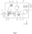
- FIG. 1 is a diagram showing an example of a schematic configuration of a printer apparatus according to an embodiment.
- the printer apparatus 10 is a so-called thermal transfer printer that prints on a label 122 (see Fig. 2 ) placed on label paper 12 by heating an ink ribbon 22.
- the printer apparatus 10 prints on the label paper 12 while pulling out the label paper 12 from rolled paper 11 that is the label paper 12 wound into a roll.
- the structure of the label paper 12 will be described below in detail (see Fig. 2 ).
- the label paper 12 is an example of printing paper in the present disclosure.
- the printer apparatus 10 includes, inside a casing 20, a conveying roller 13, a pinch roller 14, a platen roller 15, and a thermal head 23.
- the conveying roller 13 is driven to rotate counterclockwise or clockwise by a drive motor 131.
- the pinch roller 14 sandwiches the label paper 12 between the pinch roller 14 and the conveying roller 13.
- the pinch roller 14 rotates along with the counterclockwise rotation of the conveying roller 13 to convey (feed) the label paper 12 pulled out from the rolled paper 11 toward a paper ejection port 27 in forward rotation along the direction of an arrow C. Note that in the following description, conveying in forward rotation will be referred to simply as conveying in some cases.
- the pinch roller 14 rotates along with the clockwise rotation of the conveying roller 13 to convey (back-feed) the label paper 12 from the paper ejection port 27 toward the upstream side in reverse rotation along the direction of an arrow D.
- the platen roller 15 is driven to rotate counterclockwise by a drive motor 151.
- the platen roller 15 conveys the label paper 12 sandwiched between the platen roller 15 and the thermal head 23 toward the paper ejection port 27 along the direction of the arrow C.
- the platen roller 15 conveys the label paper 12 while the thermal head 23 and the platen roller 15 abut on each other. Meanwhile, the conveying roller 13 and the pinch roller 14 conveys the label paper 12 while the thermal head 23 and the platen roller 15 do not abut on each other.
- the thermal head 23 has a structure in which a plurality of heating elements is aligned, and prints on the label paper 12 sandwiched between the thermal head 23 and the platen roller 15 by causing the heating element corresponding to the printing pattern to generate heat.
- the thermal head 23 ascends by the action of a solenoid 26 in the direction of an arrow A (Z-axis positive direction). Further, the thermal head 23 descends by the action of the solenoid 26 in the direction of an arrow B (Z-axis negative direction). This allows it to switch between the state where the thermal head 23 and the platen roller 15 abut on each other (head-down state) and the state where the thermal head 23 and the platen roller 15 do not abut on each other (head-up state).
- the thermal head 23 is an example of a print head in the present disclosure.
- the ink ribbon 22 is inserted between the thermal head 23 and the platen roller 15.
- the ink ribbon 22 is wound to form a ribbon roll 21 while the ink ribbon 22 is not in use.
- the ink ribbon 22 is wound up on a winding shaft 24 that is driven to rotate clockwise by a drive motor 241 and moves in the direction of an arrow E.
- the ink applied to the ink ribbon 22 melts by the heated thermal head 23 and is transferred to the label paper 12.
- the ink ribbon 22 is conveyed while being in contact with the label paper 12 at the position of the thermal head 23 and is wound up by the winding shaft 24.
- the ink ribbon 22 is wound up by the winding shaft 24 even in the case where printing on the label paper 12 is not performed for a long time, which ends up as waste.
- the printer apparatus 10 makes the thermal head 23 in the head-up state such that the thermal head 23 and the platen roller 15 do not abut on each other.
- the printer apparatus 10 further stops the drive motor 241 to stop the conveyance of the ink ribbon 22.
- the label paper 12 that has been printed is further conveyed and ejected from the paper ejection port 27.
- the label paper 12 that has been printed and ejected from the paper ejection port 27 may be cut by hand at the position of the paper ejection port 27 or may be cut by a cutter installed in the vicinity of the paper ejection port 27 depending on the printer apparatus 10.
- attachments 30 are attached to the paper ejection port 27 of the printer apparatus 10 in some cases.
- the attachment 30 include a cutter unit that cuts the printed label paper 12, a peeling unit that peels off a label from the printed label paper 12, and an RFID module that writes information to a wireless tag (e.g., RFID tag) embedded in the printed label paper 12.
- a wireless tag e.g., RFID tag
- FIG. 2 is a diagram showing an example of a structure of label paper on which printing is performed by the printer apparatus.
- the label paper 12 has a structure in which a plurality of labels 122 having the same size is placed on mounting paper 121 at predetermined intervals.
- the label 122 may be one that includes an adhesive layer on the back surface thereof and is attached to the mounting paper 121 that is release paper in a peelable manner.
- the label 122 may contain a wireless tag (e.g., RFID tag).
- a wireless tag e.g., RFID tag
- the length of the label 122 along the conveying direction is a label length L as shown in Fig. 2 .
- the distance between the thermal head 23 and the paper ejection port 27 in the printer apparatus 10 is a distance Da between a thermal head and a paper ejection port shown in Fig. 2 .
- the distance between the paper ejection port 27 and the paper ejection port of the attachment 30 is an attachment extension distance Db shown in Fig. 2 .
- the printer apparatus 10 In the case where the attachment 30 is not attached to the printer apparatus 10, the printer apparatus 10 needs to expose at least the entire label 122 that has been printed outside the paper ejection port 27 by conveying the tip of the label paper 12 that has been printed. For this reason, the printer apparatus 10 conveys the label paper 12 that has been printed in the X-axis positive direction in Fig. 2 by the amount corresponding to the label length L and the distance Da between a thermal head and a paper ejection port.
- the printer apparatus 10 needs to expose at least the entire label 122 that has been printed outside the paper ejection port of the attachment 30 by conveying the tip of the label paper 12 that has been printed. For this reason, the printer apparatus 10 conveys the label paper 12 that has been printed in the X-axis positive direction in Fig. 2 by the amount corresponding to the label length L, the distance Da between a thermal head and a paper ejection port, and the attachment extension distance Db.
- the printer apparatus 10 includes a processor 100.
- Fig. 3 is a functional block diagram showing an example of the functional configuration of the processor 100 of the printer apparatus according to the embodiment.
- the processor 100 of the printer apparatus 10 includes an attachment information acquisition processor 41, a presence/absence-of-head-up-function acquisition processor 42, a setting processor 44, a printing data acquisition processor 45, an operation control processor 46, a job management processor 47, a command analysis processor 48, and an engine control processor 49 shown in Fig. 3 .
- the processor 100 is, for example, a CPU.
- the processor 100 is realized by a control program operated by the CPU. Note that part or all of the processor 100 may be realized by dedicated hardware.
- the attachment information acquisition processor 41 acquires information indicating whether or not the attachment 30 is attached to the paper ejection port 27 of the printer apparatus 10 and the attachment extension distance Db of the attachment 30 in the case where the attachment 30 is attached to the paper ejection port 27.
- the attachment information acquisition processor 41 acquires information for specifying the attached attachment 30 in accordance with a user's instruction. Further, the attachment information acquisition processor 41 may uniquely specify the type of attached attachment 30 by the contact between an electrical contact of the attachment 30 and an electrical contact of the printer apparatus 10.
- the presence/absence-of-head-up-function acquisition processor 42 acquires information indicating whether or not the printer apparatus 10 has a head-up function. Specifically, the presence/absence-of-head-up-function acquisition processor 42 determines whether or not the printer apparatus 10 has a head-up function by referring to the content of a function master file (not shown) that is stored in the printer apparatus 10 and shows a list of functions that the printer apparatus 10 has.
- the setting processor 44 sets various settings relating to the conveyance of the label paper 12 when using the printer apparatus 10 to print.
- the setting processor 44 further includes a feeding amount setting unit 441, a back-feeding amount setting unit 442, a minimum label pitch setting unit 443, and a fine adjustment amount setting unit 444.
- the feeding amount setting unit 441 sets, in accordance with the distance acquired by the attachment information acquisition processor 41, a feeding amount of the label paper 12 after printing when ejecting the label paper 12 after printing from the paper ejection port of the attachment 30.
- the back-feeding amount setting unit 442 sets, in accordance with the presence or absence of the head-up function of the printer apparatus 10, a back-feeding amount when conveying the label paper 12 after printing, which has been ejected from the paper ejection port of the attachment 30, to the position for the next printing in reverse rotation.
- the minimum label pitch setting unit 443 sets, in accordance with the presence or absence of the head-up function of the printer apparatus 10, the minimum value of the label pitch P that is the interval between upstream end portions of the labels 122 adjacent to each other in the label paper 12 or the interval between downstream end portions of the labels 122 adjacent to each other in the label paper 12.
- the fine adjustment amount setting unit 444 sets the fine adjustment amount of the feeding amount of the label paper 12 after printing in accordance with the presence or absence of the head-up function of the printer apparatus 10. Specifically, in the case where the printer apparatus 10 has a head-up function, the fine adjustment amount setting unit 444 sets a fine adjustment amount Za (see Fig. 4 ) of the feeding amount and the back-feeding amount of the label paper 12 after printing. Meanwhile, in the case where the printer apparatus 10 does not have a head-up function, the fine adjustment amount setting unit 444 sets a fine adjustment amount Zb (see Fig. 4 ) of the feeding amount and the back-feeding amount of the label paper 12 after printing. Note that the fine adjustment amount of the feeding amount and the fine adjustment amount of the back-feeding amount may be set to have different values.
- the fine adjustment amount setting unit 444 may set the fine adjustment amount by, for example, referring to a setting map of the fine adjustment amount according to the type of label paper 12, which is stored in the printer apparatus 10 in advance. Further, the setting map of the fine adjustment amount may store the fine adjustment amount according to the presence or absence of the head-up function and the type of label paper 12.
- the printing data acquisition processor 45 acquires printing data to be printed on the printer apparatus 10. Specifically, the printing data acquisition processor 45 acquires printing data from an external device such as a personal computer connected to the printer apparatus 10.
- the operation control processor 46 acquires an operation instruction such as a printing instruction to the printer apparatus 10.
- the job management processor 47 manages a job acquired from the command analysis processor 48. Further, the job management processor 47 outputs various instructions relating to printing to the engine control processor 49.
- the command analysis processor 48 analyzes the command and printing data given to the printer apparatus 10. Further, the command analysis processor 48 outputs the analysis result of the command to the job management processor 47 and the engine control processor 49.
- the engine control processor 49 controls the respective units (the thermal head 23 and the drive motors 131, 151, and 241 (see Fig. 1 )) and the like of the printer apparatus 10.
- the engine control processor 49 further includes a conveyance control unit 491 and a printing control unit 492.
- the conveyance control unit 491 controls conveyance of the label paper 12 and the ink ribbon 22. Further, in the case where printing data has a certain continuous area that does not need to be printed, the conveyance control unit 491 moves the thermal head 23 up and stops the conveyance of the ink ribbon 22 to save ribbons. Further, the conveyance control unit 491 performs conveyance and reverse conveyance of the label paper 12 after printing in accordance with the type of attachment 30 attached to the printer apparatus 10 and the presence or absence of the head-up function of the printer apparatus 10. That is, the conveyance control unit 491 ejects the label paper 12 after printing by just the feeing amount set by the feeding amount setting unit 441.
- the conveyance control unit 491 conveys the label paper 12 in reverse rotation by just the back-feeding amount set by the back-feeding amount setting unit 442.
- the conveyance control unit 491 is an example of a feeding control unit and a back-feeding control unit in the present disclosure.
- the printing control unit 492 draws the printing data acquired from the command analysis processor 48.
- the printer apparatus 10 includes a memory 200 in which a table of the various parameters is stored.
- Fig. 4 is a diagram describing the configuration of the memory 200 in which a table of various parameters is stored in the printer apparatus 10 according to the embodiment.
- the printer apparatus 10 stores, as various parameters, parameters of the distance Da between a thermal head and a paper ejection port, the attachment extension distance Db, the fine adjustment amount Za, the fine adjustment amount Zb, the gap G between labels, and the minimum label pitch in the memory 200.
- the distance Da between a thermal head and a paper ejection port is a distance between the thermal head 23 and the paper ejection port 27 as described with reference to Fig. 2 .
- the distance Da between a thermal head and a paper ejection port is a value that is uniquely determined for each printer apparatus 10.
- the attachment extension distance Db is a distance between the paper ejection port 27 and the paper ejection port of the attachment 30 as described with reference to Fig. 2 .
- the attachment extension distance Db is a value that is uniquely determined for each type of attachment 30.
- the fine adjustment amount Za is a fine adjustment amount of the feeding amount and the back-feeding amount to be set in the case where the printer apparatus 10 does not have a head-up function.
- the fine adjustment amount Zb is a fine adjustment amount of the feeding amount and the back-feeding amount to be set in the case where the printer apparatus 10 does not have a head-up function.
- fine adjustment amounts Za and Zb may be further set in accordance with the type of label paper 12.
- the gap G between labels is a distance between the labels 122 adjacent to each other as described with reference to Fig. 2 .
- the feeding amount of the label paper 12 is set so that it can be cut at a position within the range of the gap G between labels.
- the feeding amount differs depending on the presence or absence of the head-up function or the type of label paper 12
- the label paper 12 can be cut at an appropriate position regardless of the presence or absence of the head-up function and the type of label paper 12.
- a minimum label pitch Pa is the minimum value of the printable label pitch P to be set in the case where the printer apparatus 10 has a head-up function. Further, a minimum label pitch Pb is the minimum value of the printable label pitch P to be set in the case where the printer apparatus 10 does not have a head-up function.
- the printer apparatus 10 has a head-up function
- the label 122 does not get caught in the thermal head 23.
- the magnitude relationship between the minimum label pitch Pa and the minimum label pitch Pb satisfies Pa > Pb.
- the printer apparatus 10 stores the table shown in Fig. 4 in the memory 200 in advance, and the above-mentioned setting processor 44 sets various parameters by referring to this table.
- Fig. 5 is a flowchart showing an example of feeding amount setting processing performed by the processor 100 of the printer apparatus 10 according to the embodiment. Note that the target of feeding amount setting processing is the printer apparatus 10 in which the label paper 12 having the label pitch P of the minimum label pitch shown in Fig. 4 or more is set.
- Step S11 the attachment information acquisition processor 41 determines whether or not the attachment 30 is attached to the printer apparatus 10. In the case where it is determined that the attachment 30 is attached to the printer apparatus 10 (Step 511: Yes) the processing of the processor 100 proceeds to Step S12. Meanwhile, in the case where it is determined that the attachment 30 is not attached to the printer apparatus 10 (Step S11: No), the processing of the processor 100 proceeds to Step S13.
- Step S11 Yes
- the setting processor 44 sets, by the feeding amount setting unit 441, the feeding amount of the label paper 12 after printing to Da + Db in Step S12. After that, the processing of the processor 100 proceeds to Step S14.
- Da is a distance between a thermal head and a paper ejection port and Db is an attachment extension distance.
- Step S11 the setting processor 44 sets, by the feeding amount setting unit 441, the feeding amount of the label paper 12 after printing to Da in Step S13. After that, the processing of the processor 100 proceeds to Step S14.
- Step S14 the presence/absence-of-head-up-function acquisition processor 42 determine whether or not the printer apparatus 10 has a head-up function. In the case where it is determined that the printer apparatus 10 has a head-up function (Step S14: Yes), the processing of the processor 100 proceeds to Step S15. Meanwhile, in the case where it is determined that the printer apparatus 10 does not have a head-up function (Step S14: No), the processing of the processor 100 proceeds to Step S16.
- Step S14 the setting processor 44 sets, by the fine adjustment amount setting unit 444, the fine adjustment amount of the feeding amount to Za in Step S15. After that, the processor 100 of the printer apparatus 10 ends the feeding amount setting processing.
- Step S14 the setting processor 44 sets, by the fine adjustment amount setting unit 444, the fine adjustment amount of the feeding amount to Zb in Step S16. After that, the processor 100 of the printer apparatus 10 ends the feeding amount setting processing.
- Fig. 6 is a flowchart showing an example of the back-feeding amount setting processing performed by the processor 100 of the printer apparatus 10 according to the embodiment. Note that the target of back-feeding amount setting processing is the printer apparatus 10 in which the label paper 12 is set, the feeding amount setting processing shown in Fig. 5 having been performed on the printer apparatus 10.
- Step S21 the presence/absence-of-head-up-function acquisition processor 42 determines whether or not the printer apparatus 10 has a head-up function. In the case where it is determined that the printer apparatus 10 has a head-up function (Step S21: Yes), the processing of the processor 100 proceeds to Step S22. Meanwhile, in the case where it is determined that the printer apparatus 10 does not have a head-up function (Step S21: No), the processing of the processor 100 proceeds to Step S25.
- Step S21: Yes the attachment information acquisition processor 41 determines whether or not the attachment 30 is attached to the printer apparatus 10 in Step S22. In the case where it is determined that the attachment 30 is attached to the printer apparatus 10 (Step S22: Yes), the processing of the processor 100 proceeds to Step S23. Meanwhile, in the case where it is determined that the attachment 30 is attached to the printer apparatus 10 (Step S22: No), the processing of the processor 100 proceeds to Step S24.
- the setting processor 44 sets, by the back-feeding amount setting unit 442, the back-feeding amount of the label paper 12 to Da + Db + Za in Step S23. After that, the processor 100 of the printer apparatus 10 ends the back-feeding amount setting processing.
- the setting processor 44 sets, by the back-feeding amount setting unit 442, the back-feeding amount of the label paper 12 to Da + Za in Step S24. After that, the processor 100 of the printer apparatus 10 ends the back-feeding amount setting processing.
- the attachment information acquisition processor 41 determines whether or not the attachment 30 is attached to the printer apparatus 10 in Step S25. In the case where it is determined that the attachment 30 is attached to the printer apparatus 10 (Step S25: Yes), the processing of the processor 100 proceeds to Step S26. Meanwhile, in the case where it is determined that the attachment 30 is not attached to the printer apparatus 10 (Step S25: No), the processing of the processor 100 proceeds to Step S27.
- the setting processor 44 sets, by the back-feeding amount setting unit 442, the back-feeding amount of the label paper 12 to Da + Db + Zb in Step S26. After that, the processor 100 of the printer apparatus 10 ends the back-feeding amount setting processing.
- the setting processor 44 sets, by the back-feeding amount setting unit 442, the back-feeding amount of the label paper 12 to Da + Zb in Step S27. After that, the processor 100 of the printer apparatus 10 ends the back-feeding amount setting processing.
- fine adjustment amount during conveyance and the fine adjustment amount during reverse conveyance have been described to be set to have equal values in Fig. 5 and Fig. 6
- the fine adjustment amount during conveyance and the fine adjustment amount during reverse conveyance may be set to have different values in accordance with the type of label paper 12 to be used, or the like.
- the printer apparatus 10 After ending the feeding amount setting processing in Fig. 5 and the back-feeding amount setting processing in Fig. 6 , the printer apparatus 10 receives a printing instruction and executes necessary printing. Since the execution of printing is the same as the processing performed by a general printer apparatus, description thereof is omitted.
- the printer apparatus 10 is a thermal transfer printer apparatus that prints on the label paper 12 (printing paper) by heating the ink ribbon 22 or a thermal printer apparatus that prints on the thermal label paper 12 (printing paper).
- the printer apparatus 10 includes the attachment information acquisition processor 41, the setting processor 44 (the feeding amount setting unit 441, the back-feeding amount setting unit 442), and the engine control processor 49 (the conveyance control unit 491).
- the attachment information acquisition processor 41 acquires the distance from the paper ejection port 27 that ejects the label paper 12 printed by the printer apparatus 10 to the paper ejection port of the attachment 30 (the attachment extension distance Db) connected to the paper ejection port 27.
- the setting processor 44 sets, by the feeding amount setting unit 441, the feeding amount of the label paper 12 after printing when the label paper 12 after printing is ejected from the paper ejection port of the attachment 30 in accordance with the acquired attachment extension distance Db.
- the engine control processor 49 conveys, by the conveyance control unit 491 (feeding control unit), the label paper 12 by just the set feeding amount in order to eject the label paper 12 after printing.
- the setting processor 44 sets, by the back-feeding amount setting unit 442, the back-feeding amount when conveying the label paper 12 ejected from the paper ejection port of the attachment 30 to the position for the next printing in reverse rotation in accordance with the presence or absence of the head-up function of the printer apparatus 10.
- the engine control processor 49 conveys, by the conveyance control unit 491 (back-feeding control unit), the label paper 12 in reverse rotation by just the set back-feeding amount. Therefore, it is possible to set an appropriate feeding amount and an appropriate back-feeding amount in accordance with the presence or absence of the head-up function of the printer apparatus 10, and thus, it is possible to reliably prevent the label 122 from getting caught in the thermal head 23 (print head) when conveying the conveyed label paper 12 in rotation in preparation for the next printing.
- the feeding amount setting unit 441 of the setting processor 44 sets, as a feeding amount, the distance obtained by adding the distance that the label paper 12 (printing paper) passes through the attachment 30 to the distance between the thermal head 23 (print head) and the paper ejection port 27 of the printer apparatus 10. Therefore, it is possible to set an appropriate feeding amount in accordance with the type of attachment 30 attached to the printer apparatus 10.
- the setting processor 44 of the printer apparatus 10 further sets, by the fine adjustment amount setting unit 444, the fine adjustment amounts Za and Zb of the feeding amount in accordance with the presence or absence of a head-up function. Therefore, it is possible to realize an accurate feeding amount in accordance with the presence or absence of the head-up function of the printer apparatus 10.
- printing paper is the label paper 12 in which the plurality of labels 122 is placed on the mounting paper 121 at predetermined intervals. Therefore, even with printing paper in which the thick label 122 is attached to the mounting paper 121, it is possible to prevent the label 122 from getting caught in the thermal head 23 during reverse conveyance.
- the setting processor 44 of the printer apparatus 10 further sets, by the minimum label pitch setting unit 443, the minimum value of the label pitch that is the interval between upstream end portions of the labels 122 adjacent to each other in the label paper 12 (printing paper) or the interval between downstream end portions of the labels 122 adjacent to each other in the label paper 12 (printing paper) in accordance with the presence or absence of a head-up function. Therefore, it is possible to select the label paper 12 on which printing can be performed by the printer apparatus 10.
Landscapes
- Handling Of Sheets (AREA)
- Printers Characterized By Their Purpose (AREA)
- Electronic Switches (AREA)
Abstract
Description
- An embodiment to be described here generally relates to a printer apparatus.
- In the past, a thermal transfer printer apparatus that prints on printing paper by heating an ink ribbon and a thermal printer apparatus that prints on thermal printing paper have been known.
- When printing with such an existing printer apparatus, the trailing edge of the label gets caught in a thermal head during reverse conveyance of label paper, which causes deformation or turning up of the label in some cases. In order to prevent the turning up from occurring, it has been common practice to set a limit on the label length such that the trailing edge of the label does not go beyond the thermal head in the case where the label paper after printing is conveyed to the cutting position. Therefore, in the case where the feeding distance of the label paper after printing is long, e.g., in the case of printing on a label with a short label length or attaching various attachments to a paper ejection port, there has been a problem that the label gets caught in the thermal head during reverse conveyance of the label paper.
- To this end, a printer apparatus according to the appended claims are provided.
-
-
Fig. 1 is a diagram showing an example of a printer apparatus according to an embodiment. -
Fig. 2 is a diagram showing an example of a structure of label paper on which printing is performed by the printer apparatus according to the embodiment. -
Fig. 3 is a functional block diagram showing an example of a functional configuration of the printer apparatus according to the embodiment. -
Fig. 4 is a diagram describing various parameters to be set by the printer apparatus according to the embodiment. -
Fig. 5 is a flowchart showing an example of feeding amount setting processing to be performed by the printer apparatus according to the embodiment. -
Fig. 6 is a flowchart showing an example of back-feeding amount setting processing performed by the printer apparatus according to the embodiment. - According to an embodiment, a printer apparatus includes a print head for printing on printing paper. The printer apparatus includes an apparatus that has a head-up function for moving the print head between a position where printing on the printing paper is available and a position where printing on the printing paper is not available and an apparatus that does not have the head-up function. The printer apparatus includes: a casing; an attachment; a conveying device; an information acquisition processor; a setting processor; and an engine control processor. The casing includes a paper ejection port for ejecting the printed printing paper. The attachment includes a paper ejection port for receiving the printing paper ejected from the casing and then ejecting the received printing paper and is detachably/attachably connected to the paper ejection port of the casing. The conveying device conveys the printing paper after printing in forward rotation to eject the printing paper from the paper ejection port of the attachment and conveys the printing paper in reverse rotation for next printing. The information acquisition processor acquires information from the paper ejection port of the casing to the paper ejection port of the attachment. The setting processor sets, in accordance with the acquired distance, a feeding amount of the printing paper after printing when ejecting the printing paper after printing from the paper ejection port of the attachment. Further, the setting processor sets, in accordance with presence or absence of the head-up function, a back-feeding amount when conveying the printing paper ejected from the paper ejection port of the attachment to a position for next printing in reverse rotation. The engine control processor causes the conveying device to convey the printing paper in forward rotation by the set feeding amount to eject the printing paper after printing. Further, the engine control processor causes the conveying device to convey the printing paper in reverse rotation by the set back-feeding amount to return the printing paper to a next printing position before next printing.
- An embodiment will be described below in detail with reference to the drawings. In the drawings, the same reference symbols denote the same or similar portions. Note that the embodiment is not limited by the following description.
- A schematic configuration of a
printer apparatus 10 according to an embodiment will be described with reference toFig 1. Fig. 1 is a diagram showing an example of a schematic configuration of a printer apparatus according to an embodiment. - The
printer apparatus 10 is a so-called thermal transfer printer that prints on a label 122 (seeFig. 2 ) placed onlabel paper 12 by heating anink ribbon 22. Theprinter apparatus 10 prints on thelabel paper 12 while pulling out thelabel paper 12 from rolledpaper 11 that is thelabel paper 12 wound into a roll. The structure of thelabel paper 12 will be described below in detail (seeFig. 2 ). Note that thelabel paper 12 is an example of printing paper in the present disclosure. - The
printer apparatus 10 includes, inside acasing 20, aconveying roller 13, apinch roller 14, aplaten roller 15, and athermal head 23. - The conveying
roller 13 is driven to rotate counterclockwise or clockwise by adrive motor 131. - The
pinch roller 14 sandwiches thelabel paper 12 between thepinch roller 14 and theconveying roller 13. Thepinch roller 14 rotates along with the counterclockwise rotation of theconveying roller 13 to convey (feed) thelabel paper 12 pulled out from the rolledpaper 11 toward apaper ejection port 27 in forward rotation along the direction of an arrow C. Note that in the following description, conveying in forward rotation will be referred to simply as conveying in some cases. - Further, the
pinch roller 14 rotates along with the clockwise rotation of theconveying roller 13 to convey (back-feed) thelabel paper 12 from thepaper ejection port 27 toward the upstream side in reverse rotation along the direction of an arrow D. - The
platen roller 15 is driven to rotate counterclockwise by adrive motor 151. Theplaten roller 15 conveys thelabel paper 12 sandwiched between theplaten roller 15 and thethermal head 23 toward thepaper ejection port 27 along the direction of the arrow C. - Note that the
platen roller 15 conveys thelabel paper 12 while thethermal head 23 and theplaten roller 15 abut on each other. Meanwhile, the conveyingroller 13 and thepinch roller 14 conveys thelabel paper 12 while thethermal head 23 and theplaten roller 15 do not abut on each other. - The
thermal head 23 has a structure in which a plurality of heating elements is aligned, and prints on thelabel paper 12 sandwiched between thethermal head 23 and theplaten roller 15 by causing the heating element corresponding to the printing pattern to generate heat. Note that thethermal head 23 ascends by the action of asolenoid 26 in the direction of an arrow A (Z-axis positive direction). Further, thethermal head 23 descends by the action of thesolenoid 26 in the direction of an arrow B (Z-axis negative direction). This allows it to switch between the state where thethermal head 23 and theplaten roller 15 abut on each other (head-down state) and the state where thethermal head 23 and theplaten roller 15 do not abut on each other (head-up state). Note that thethermal head 23 is an example of a print head in the present disclosure. - Note that the
ink ribbon 22 is inserted between thethermal head 23 and theplaten roller 15. Theink ribbon 22 is wound to form aribbon roll 21 while theink ribbon 22 is not in use. Theink ribbon 22 is wound up on awinding shaft 24 that is driven to rotate clockwise by adrive motor 241 and moves in the direction of an arrow E. The ink applied to theink ribbon 22 melts by the heatedthermal head 23 and is transferred to thelabel paper 12. - The
ink ribbon 22 is conveyed while being in contact with thelabel paper 12 at the position of thethermal head 23 and is wound up by thewinding shaft 24. However, theink ribbon 22 is wound up by thewinding shaft 24 even in the case where printing on thelabel paper 12 is not performed for a long time, which ends up as waste. For this reason, in the case where printing on thelabel paper 12 is not performed for a long time, theprinter apparatus 10 makes thethermal head 23 in the head-up state such that thethermal head 23 and theplaten roller 15 do not abut on each other. At this time, theprinter apparatus 10 further stops thedrive motor 241 to stop the conveyance of theink ribbon 22. As a result, only thelabel paper 12 is conveyed, which makes it possible to reduce the consumption of theink ribbon 22. That is, by using the head-up function, it is possible to reduce the consumption of theink ribbon 22, i.e., save ribbons. - The
label paper 12 that has been printed is further conveyed and ejected from thepaper ejection port 27. Note that thelabel paper 12 that has been printed and ejected from thepaper ejection port 27 may be cut by hand at the position of thepaper ejection port 27 or may be cut by a cutter installed in the vicinity of thepaper ejection port 27 depending on theprinter apparatus 10. -
Various attachments 30 are attached to thepaper ejection port 27 of theprinter apparatus 10 in some cases. Examples of theattachment 30 include a cutter unit that cuts the printedlabel paper 12, a peeling unit that peels off a label from the printedlabel paper 12, and an RFID module that writes information to a wireless tag (e.g., RFID tag) embedded in the printedlabel paper 12. - A structure of the
label paper 12 will be described with reference toFig. 2. Fig. 2 is a diagram showing an example of a structure of label paper on which printing is performed by the printer apparatus. - The
label paper 12 has a structure in which a plurality oflabels 122 having the same size is placed on mountingpaper 121 at predetermined intervals. Note that thelabel 122 may be one that includes an adhesive layer on the back surface thereof and is attached to the mountingpaper 121 that is release paper in a peelable manner. - Further, the
label 122 may contain a wireless tag (e.g., RFID tag). - The length of the
label 122 along the conveying direction is a label length L as shown inFig. 2 . - There is a gap corresponding to a gap G between labels between the
labels 122 adjacent to each other in the conveying direction. - A distance between the end portion of a
certain label 122 on the downstream side and the end portion of thelabel 122 adjacent thereto on the downstream side has a value corresponding to a label pitch P (= L + G). - Note that the distance between the
thermal head 23 and thepaper ejection port 27 in theprinter apparatus 10 is a distance Da between a thermal head and a paper ejection port shown inFig. 2 . Further, when theattachment 30 is attached to theprinter apparatus 10, the distance between thepaper ejection port 27 and the paper ejection port of theattachment 30 is an attachment extension distance Db shown inFig. 2 . - In the case where the
attachment 30 is not attached to theprinter apparatus 10, theprinter apparatus 10 needs to expose at least theentire label 122 that has been printed outside thepaper ejection port 27 by conveying the tip of thelabel paper 12 that has been printed. For this reason, theprinter apparatus 10 conveys thelabel paper 12 that has been printed in the X-axis positive direction inFig. 2 by the amount corresponding to the label length L and the distance Da between a thermal head and a paper ejection port. - Further, in the case where the
attachment 30 is attached to theprinter apparatus 10, theprinter apparatus 10 needs to expose at least theentire label 122 that has been printed outside the paper ejection port of theattachment 30 by conveying the tip of thelabel paper 12 that has been printed. For this reason, theprinter apparatus 10 conveys thelabel paper 12 that has been printed in the X-axis positive direction inFig. 2 by the amount corresponding to the label length L, the distance Da between a thermal head and a paper ejection port, and the attachment extension distance Db. - A functional configuration of the
printer apparatus 10 according to the embodiment will be described with reference toFig. 3 . Theprinter apparatus 10 includes aprocessor 100.Fig. 3 is a functional block diagram showing an example of the functional configuration of theprocessor 100 of the printer apparatus according to the embodiment. - The
processor 100 of theprinter apparatus 10 includes an attachment information acquisition processor 41, a presence/absence-of-head-up-function acquisition processor 42, a setting processor 44, a printing data acquisition processor 45, anoperation control processor 46, ajob management processor 47, acommand analysis processor 48, and anengine control processor 49 shown inFig. 3 . - The
processor 100 is, for example, a CPU. Theprocessor 100 is realized by a control program operated by the CPU. Note that part or all of theprocessor 100 may be realized by dedicated hardware. - The attachment information acquisition processor 41 acquires information indicating whether or not the
attachment 30 is attached to thepaper ejection port 27 of theprinter apparatus 10 and the attachment extension distance Db of theattachment 30 in the case where theattachment 30 is attached to thepaper ejection port 27. - Specifically, the attachment information acquisition processor 41 acquires information for specifying the attached
attachment 30 in accordance with a user's instruction. Further, the attachment information acquisition processor 41 may uniquely specify the type of attachedattachment 30 by the contact between an electrical contact of theattachment 30 and an electrical contact of theprinter apparatus 10. - The presence/absence-of-head-up-
function acquisition processor 42 acquires information indicating whether or not theprinter apparatus 10 has a head-up function. Specifically, the presence/absence-of-head-up-function acquisition processor 42 determines whether or not theprinter apparatus 10 has a head-up function by referring to the content of a function master file (not shown) that is stored in theprinter apparatus 10 and shows a list of functions that theprinter apparatus 10 has. - The setting processor 44 sets various settings relating to the conveyance of the
label paper 12 when using theprinter apparatus 10 to print. - The setting processor 44 further includes a feeding amount setting unit 441, a back-feeding
amount setting unit 442, a minimum labelpitch setting unit 443, and a fine adjustmentamount setting unit 444. - The feeding amount setting unit 441 sets, in accordance with the distance acquired by the attachment information acquisition processor 41, a feeding amount of the
label paper 12 after printing when ejecting thelabel paper 12 after printing from the paper ejection port of theattachment 30. - The back-feeding
amount setting unit 442 sets, in accordance with the presence or absence of the head-up function of theprinter apparatus 10, a back-feeding amount when conveying thelabel paper 12 after printing, which has been ejected from the paper ejection port of theattachment 30, to the position for the next printing in reverse rotation. - The minimum label
pitch setting unit 443 sets, in accordance with the presence or absence of the head-up function of theprinter apparatus 10, the minimum value of the label pitch P that is the interval between upstream end portions of thelabels 122 adjacent to each other in thelabel paper 12 or the interval between downstream end portions of thelabels 122 adjacent to each other in thelabel paper 12. - The fine adjustment
amount setting unit 444 sets the fine adjustment amount of the feeding amount of thelabel paper 12 after printing in accordance with the presence or absence of the head-up function of theprinter apparatus 10. Specifically, in the case where theprinter apparatus 10 has a head-up function, the fine adjustmentamount setting unit 444 sets a fine adjustment amount Za (seeFig. 4 ) of the feeding amount and the back-feeding amount of thelabel paper 12 after printing. Meanwhile, in the case where theprinter apparatus 10 does not have a head-up function, the fine adjustmentamount setting unit 444 sets a fine adjustment amount Zb (seeFig. 4 ) of the feeding amount and the back-feeding amount of thelabel paper 12 after printing. Note that the fine adjustment amount of the feeding amount and the fine adjustment amount of the back-feeding amount may be set to have different values. - Further, even in the
same printer apparatus 10, the frictional force with each type of roller included in theprinter apparatus 10 differs in some cases depending on the material of thelabel paper 12 to be used, or the like. For this reason, even if the same conveyance amount is set in theprinter apparatus 10, there are differences in the actual amount of conveyance of thelabel paper 12 in some cases depending on the type oflabel paper 12. Each of the fine adjustment amounts Za and Zb is a type of bias value for suppressing such variations in conveyance amount. The fine adjustmentamount setting unit 444 may set the fine adjustment amount by, for example, referring to a setting map of the fine adjustment amount according to the type oflabel paper 12, which is stored in theprinter apparatus 10 in advance. Further, the setting map of the fine adjustment amount may store the fine adjustment amount according to the presence or absence of the head-up function and the type oflabel paper 12. - The printing data acquisition processor 45 acquires printing data to be printed on the
printer apparatus 10. Specifically, the printing data acquisition processor 45 acquires printing data from an external device such as a personal computer connected to theprinter apparatus 10. - The
operation control processor 46 acquires an operation instruction such as a printing instruction to theprinter apparatus 10. - The
job management processor 47 manages a job acquired from thecommand analysis processor 48. Further, thejob management processor 47 outputs various instructions relating to printing to theengine control processor 49. - The
command analysis processor 48 analyzes the command and printing data given to theprinter apparatus 10. Further, thecommand analysis processor 48 outputs the analysis result of the command to thejob management processor 47 and theengine control processor 49. - The
engine control processor 49 controls the respective units (thethermal head 23 and thedrive motors Fig. 1 )) and the like of theprinter apparatus 10. - The
engine control processor 49 further includes aconveyance control unit 491 and aprinting control unit 492. - The
conveyance control unit 491 controls conveyance of thelabel paper 12 and theink ribbon 22. Further, in the case where printing data has a certain continuous area that does not need to be printed, theconveyance control unit 491 moves thethermal head 23 up and stops the conveyance of theink ribbon 22 to save ribbons. Further, theconveyance control unit 491 performs conveyance and reverse conveyance of thelabel paper 12 after printing in accordance with the type ofattachment 30 attached to theprinter apparatus 10 and the presence or absence of the head-up function of theprinter apparatus 10. That is, theconveyance control unit 491 ejects thelabel paper 12 after printing by just the feeing amount set by the feeding amount setting unit 441. Further, theconveyance control unit 491 conveys thelabel paper 12 in reverse rotation by just the back-feeding amount set by the back-feedingamount setting unit 442. Note that theconveyance control unit 491 is an example of a feeding control unit and a back-feeding control unit in the present disclosure. - The
printing control unit 492 draws the printing data acquired from thecommand analysis processor 48. - Various parameters relating to settings of the feeding amount and the back-feeding amount of the
label paper 12 in theprinter apparatus 10 will be described with reference toFig. 4 . Theprinter apparatus 10 includes amemory 200 in which a table of the various parameters is stored.Fig. 4 is a diagram describing the configuration of thememory 200 in which a table of various parameters is stored in theprinter apparatus 10 according to the embodiment. As shown inFig. 4 , theprinter apparatus 10 stores, as various parameters, parameters of the distance Da between a thermal head and a paper ejection port, the attachment extension distance Db, the fine adjustment amount Za, the fine adjustment amount Zb, the gap G between labels, and the minimum label pitch in thememory 200. - The distance Da between a thermal head and a paper ejection port is a distance between the
thermal head 23 and thepaper ejection port 27 as described with reference toFig. 2 . The distance Da between a thermal head and a paper ejection port is a value that is uniquely determined for eachprinter apparatus 10. - The attachment extension distance Db is a distance between the
paper ejection port 27 and the paper ejection port of theattachment 30 as described with reference toFig. 2 . The attachment extension distance Db is a value that is uniquely determined for each type ofattachment 30. - The fine adjustment amount Za is a fine adjustment amount of the feeding amount and the back-feeding amount to be set in the case where the
printer apparatus 10 does not have a head-up function. Further, the fine adjustment amount Zb is a fine adjustment amount of the feeding amount and the back-feeding amount to be set in the case where theprinter apparatus 10 does not have a head-up function. - Note that the fine adjustment amounts Za and Zb may be further set in accordance with the type of
label paper 12. - The gap G between labels is a distance between the
labels 122 adjacent to each other as described with reference toFig. 2 . When the conveyedlabel paper 12 that has been printed is cut by hand or cut by a cutter unit, the feeding amount of thelabel paper 12 is set so that it can be cut at a position within the range of the gap G between labels. In the case where the feeding amount differs depending on the presence or absence of the head-up function or the type oflabel paper 12, by setting the above-mentioned fine adjustment amounts Za and Zb, thelabel paper 12 can be cut at an appropriate position regardless of the presence or absence of the head-up function and the type oflabel paper 12. - A minimum label pitch Pa is the minimum value of the printable label pitch P to be set in the case where the
printer apparatus 10 has a head-up function. Further, a minimum label pitch Pb is the minimum value of the printable label pitch P to be set in the case where theprinter apparatus 10 does not have a head-up function. - In the case where the
printer apparatus 10 has a head-up function, by conveying thelabel paper 12 in reverse rotation while thethermal head 23 has ascended, thelabel 122 does not get caught in thethermal head 23. For this reason, the magnitude relationship between the minimum label pitch Pa and the minimum label pitch Pb satisfies Pa > Pb. - As described above, by setting the minimum label pitches Pa and Pb according to the
printer apparatus 10, it is possible to select thelabel paper 12 on which printing can be performed by theprinter apparatus 10. - The
printer apparatus 10 stores the table shown inFig. 4 in thememory 200 in advance, and the above-mentioned setting processor 44 sets various parameters by referring to this table. - The feeding amount setting processing performed by the
processor 100 of theprinter apparatus 10 will be described with reference toFig. 5. Fig. 5 is a flowchart showing an example of feeding amount setting processing performed by theprocessor 100 of theprinter apparatus 10 according to the embodiment. Note that the target of feeding amount setting processing is theprinter apparatus 10 in which thelabel paper 12 having the label pitch P of the minimum label pitch shown inFig. 4 or more is set. - In Step S11, the attachment information acquisition processor 41 determines whether or not the
attachment 30 is attached to theprinter apparatus 10. In the case where it is determined that theattachment 30 is attached to the printer apparatus 10 (Step 511: Yes) the processing of theprocessor 100 proceeds to Step S12. Meanwhile, in the case where it is determined that theattachment 30 is not attached to the printer apparatus 10 (Step S11: No), the processing of theprocessor 100 proceeds to Step S13. - In the case where it is determined that the
attachment 30 is attached to the printer apparatus 10 (Step S11: Yes), the setting processor 44 sets, by the feeding amount setting unit 441, the feeding amount of thelabel paper 12 after printing to Da + Db in Step S12. After that, the processing of theprocessor 100 proceeds to Step S14. Note that as described above, Da is a distance between a thermal head and a paper ejection port and Db is an attachment extension distance. - Meanwhile, in the case where it is determined that the
attachment 30 is not attached to the printer apparatus 10 (Step S11: No), the setting processor 44 sets, by the feeding amount setting unit 441, the feeding amount of thelabel paper 12 after printing to Da in Step S13. After that, the processing of theprocessor 100 proceeds to Step S14. - In Step S14, the presence/absence-of-head-up-
function acquisition processor 42 determine whether or not theprinter apparatus 10 has a head-up function. In the case where it is determined that theprinter apparatus 10 has a head-up function (Step S14: Yes), the processing of theprocessor 100 proceeds to Step S15. Meanwhile, in the case where it is determined that theprinter apparatus 10 does not have a head-up function (Step S14: No), the processing of theprocessor 100 proceeds to Step S16. - In the case where it is determined that the
printer apparatus 10 has a head-up function (Step S14: Yes), the setting processor 44 sets, by the fine adjustmentamount setting unit 444, the fine adjustment amount of the feeding amount to Za in Step S15. After that, theprocessor 100 of theprinter apparatus 10 ends the feeding amount setting processing. - Meanwhile, in the case where it is determined in Step S14 that the
printer apparatus 10 does not have a head-up function (Step S14: No), the setting processor 44 sets, by the fine adjustmentamount setting unit 444, the fine adjustment amount of the feeding amount to Zb in Step S16. After that, theprocessor 100 of theprinter apparatus 10 ends the feeding amount setting processing. - The back-feeding amount setting processing performed by the
printer apparatus 10 will be described with reference toFig. 6. Fig. 6 is a flowchart showing an example of the back-feeding amount setting processing performed by theprocessor 100 of theprinter apparatus 10 according to the embodiment. Note that the target of back-feeding amount setting processing is theprinter apparatus 10 in which thelabel paper 12 is set, the feeding amount setting processing shown inFig. 5 having been performed on theprinter apparatus 10. - In Step S21, the presence/absence-of-head-up-
function acquisition processor 42 determines whether or not theprinter apparatus 10 has a head-up function. In the case where it is determined that theprinter apparatus 10 has a head-up function (Step S21: Yes), the processing of theprocessor 100 proceeds to Step S22. Meanwhile, in the case where it is determined that theprinter apparatus 10 does not have a head-up function (Step S21: No), the processing of theprocessor 100 proceeds to Step S25. - In the case where it is determined that the
printer apparatus 10 has a head-up function (Step S21: Yes), the attachment information acquisition processor 41 determines whether or not theattachment 30 is attached to theprinter apparatus 10 in Step S22. In the case where it is determined that theattachment 30 is attached to the printer apparatus 10 (Step S22: Yes), the processing of theprocessor 100 proceeds to Step S23. Meanwhile, in the case where it is determined that theattachment 30 is attached to the printer apparatus 10 (Step S22: No), the processing of theprocessor 100 proceeds to Step S24. - In the case where it is determined that the
attachment 30 is attached to the printer apparatus 10 (Step S22: Yes), the setting processor 44 sets, by the back-feedingamount setting unit 442, the back-feeding amount of thelabel paper 12 to Da + Db + Za in Step S23. After that, theprocessor 100 of theprinter apparatus 10 ends the back-feeding amount setting processing. - Meanwhile, in the case where it is determined that the
attachment 30 is not attached to the printer apparatus 10 (Step S22: No), the setting processor 44 sets, by the back-feedingamount setting unit 442, the back-feeding amount of thelabel paper 12 to Da + Za in Step S24. After that, theprocessor 100 of theprinter apparatus 10 ends the back-feeding amount setting processing. - Further, in the case where it is determined that the
printer apparatus 10 does not have a head-up function (Step S21: No), the attachment information acquisition processor 41 determines whether or not theattachment 30 is attached to theprinter apparatus 10 in Step S25. In the case where it is determined that theattachment 30 is attached to the printer apparatus 10 (Step S25: Yes), the processing of theprocessor 100 proceeds to Step S26. Meanwhile, in the case where it is determined that theattachment 30 is not attached to the printer apparatus 10 (Step S25: No), the processing of theprocessor 100 proceeds to Step S27. - In the case where it is determined that the
attachment 30 is attached to the printer apparatus 10 (Step S25: Yes), the setting processor 44 sets, by the back-feedingamount setting unit 442, the back-feeding amount of thelabel paper 12 to Da + Db + Zb in Step S26. After that, theprocessor 100 of theprinter apparatus 10 ends the back-feeding amount setting processing. - Meanwhile, in the case where it is determined that the
attachment 30 is not attached to the printer apparatus 10 (Step S25: No), the setting processor 44 sets, by the back-feedingamount setting unit 442, the back-feeding amount of thelabel paper 12 to Da + Zb in Step S27. After that, theprocessor 100 of theprinter apparatus 10 ends the back-feeding amount setting processing. - Note that although the fine adjustment amount during conveyance and the fine adjustment amount during reverse conveyance have been described to be set to have equal values in
Fig. 5 andFig. 6 , the fine adjustment amount during conveyance and the fine adjustment amount during reverse conveyance may be set to have different values in accordance with the type oflabel paper 12 to be used, or the like. - After ending the feeding amount setting processing in
Fig. 5 and the back-feeding amount setting processing inFig. 6 , theprinter apparatus 10 receives a printing instruction and executes necessary printing. Since the execution of printing is the same as the processing performed by a general printer apparatus, description thereof is omitted. - As described above, the
printer apparatus 10 according to the embodiment is a thermal transfer printer apparatus that prints on the label paper 12 (printing paper) by heating theink ribbon 22 or a thermal printer apparatus that prints on the thermal label paper 12 (printing paper). Theprinter apparatus 10 includes the attachment information acquisition processor 41, the setting processor 44 (the feeding amount setting unit 441, the back-feeding amount setting unit 442), and the engine control processor 49 (the conveyance control unit 491). The attachment information acquisition processor 41 acquires the distance from thepaper ejection port 27 that ejects thelabel paper 12 printed by theprinter apparatus 10 to the paper ejection port of the attachment 30 (the attachment extension distance Db) connected to thepaper ejection port 27. The setting processor 44 sets, by the feeding amount setting unit 441, the feeding amount of thelabel paper 12 after printing when thelabel paper 12 after printing is ejected from the paper ejection port of theattachment 30 in accordance with the acquired attachment extension distance Db. Theengine control processor 49 conveys, by the conveyance control unit 491 (feeding control unit), thelabel paper 12 by just the set feeding amount in order to eject thelabel paper 12 after printing. Further, the setting processor 44 sets, by the back-feedingamount setting unit 442, the back-feeding amount when conveying thelabel paper 12 ejected from the paper ejection port of theattachment 30 to the position for the next printing in reverse rotation in accordance with the presence or absence of the head-up function of theprinter apparatus 10. Further, theengine control processor 49 conveys, by the conveyance control unit 491 (back-feeding control unit), thelabel paper 12 in reverse rotation by just the set back-feeding amount. Therefore, it is possible to set an appropriate feeding amount and an appropriate back-feeding amount in accordance with the presence or absence of the head-up function of theprinter apparatus 10, and thus, it is possible to reliably prevent thelabel 122 from getting caught in the thermal head 23 (print head) when conveying the conveyedlabel paper 12 in rotation in preparation for the next printing. - Further, in the
printer apparatus 10 according to the embodiment, the feeding amount setting unit 441 of the setting processor 44 sets, as a feeding amount, the distance obtained by adding the distance that the label paper 12 (printing paper) passes through theattachment 30 to the distance between the thermal head 23 (print head) and thepaper ejection port 27 of theprinter apparatus 10. Therefore, it is possible to set an appropriate feeding amount in accordance with the type ofattachment 30 attached to theprinter apparatus 10. - Further, the setting processor 44 of the
printer apparatus 10 according to the embodiment further sets, by the fine adjustmentamount setting unit 444, the fine adjustment amounts Za and Zb of the feeding amount in accordance with the presence or absence of a head-up function. Therefore, it is possible to realize an accurate feeding amount in accordance with the presence or absence of the head-up function of theprinter apparatus 10. - In the
printer apparatus 10 according to the embodiment, printing paper is thelabel paper 12 in which the plurality oflabels 122 is placed on the mountingpaper 121 at predetermined intervals. Therefore, even with printing paper in which thethick label 122 is attached to the mountingpaper 121, it is possible to prevent thelabel 122 from getting caught in thethermal head 23 during reverse conveyance. - Further, the setting processor 44 of the
printer apparatus 10 according to the embodiment further sets, by the minimum labelpitch setting unit 443, the minimum value of the label pitch that is the interval between upstream end portions of thelabels 122 adjacent to each other in the label paper 12 (printing paper) or the interval between downstream end portions of thelabels 122 adjacent to each other in the label paper 12 (printing paper) in accordance with the presence or absence of a head-up function. Therefore, it is possible to select thelabel paper 12 on which printing can be performed by theprinter apparatus 10. - While certain embodiments have been described, these embodiments have been presented by way of example only, and are not intended to limit the scope of the inventions. Indeed, the novel embodiments described herein may be embodied in a variety of other forms; furthermore, various omissions, substitutions and changes in the form of the embodiments described herein may be made without departing from the scope of the inventions. The accompanying claims and their equivalents are intended to cover such forms or modifications as would fall within the scope of the inventions.
Claims (10)
- A printer apparatus that includes a print head for printing on printing paper, the printer apparatus including an apparatus that has a head-up function for moving the print head between a position where printing on the printing paper is available and a position where printing on the printing paper is not available and an apparatus that does not have the head-up function, the printer apparatus comprising:a casing that includes a paper ejection port for ejecting the printed printing paper;an attachment that includes a paper ejection port for receiving the printing paper ejected from the casing and then ejecting the received printing paper and is detachably/attachably connected to the paper ejection port of the casing;a conveying device that conveys the printing paper after printing in forward rotation to eject the printing paper from the paper ejection port of the attachment and conveys the printing paper in reverse rotation for next printing;an information acquisition processor that acquires information from the paper ejection port of the casing to the paper ejection port of the attachment;a setting processor thatsets, in accordance with the acquired distance, a feeding amount of the printing paper after printing when ejecting the printing paper after printing from the paper ejection port of the attachment, andsets, in accordance with presence or absence of the head-up function, a back-feeding amount when conveying the printing paper ejected from the paper ejection port of the attachment to a position for next printing in reverse rotation; andan engine control processor thatcauses the conveying device to convey the printing paper in forward rotation by the set feeding amount to eject the printing paper after printing, andcauses the conveying device to convey the printing paper in reverse rotation by the set back-feeding amount to return the printing paper to a next printing position before next printing.
- The printer apparatus according to claim 1, whereinthe conveying device includes a platen roller that sandwiches the printing paper between the platen roller and the print head, andthe head-up function is a function of moving the print head to a position where the printing paper is sandwiched when printing and moving the print head to a position where the printing paper is not sandwiched when not printing.
- The printer apparatus according to claim 2, wherein
the conveying device is provided on an upstream side in a conveying direction in forward rotation of the printing paper than a position where the printing paper is sandwiched between the print head and the platen roller, and conveys the printing paper in forward rotation and reverse rotation while sandwiching the printing paper. - The printer apparatus according to any one of claims 1 to 3, wherein
the setting processor sets, as the feeding amount, a distance obtained by adding a distance that the printing paper passes through the attachment to a distance between the print head and the paper ejection port of the casing. - The printer apparatus according to claim 4, wherein
the setting processor sets a fine adjustment amount of the feeding amount in accordance with the presence or absence of the head-up function. - The printer apparatus according to claim 4, wherein
the setting processorsets a first fine adjustment amount of the feeding amount in the presence of the head-up function, andsets a second fine adjustment amount of the feeding amount different from the first fine adjustment amount in the absence of the head-up function. - The printer apparatus according to any one of claims 1 to 6, wherein
the printing paper is label paper in which a plurality of labels is placed on mounting paper at predetermined intervals. - The printer apparatus according to claim 7, wherein
a label pitch that is a predetermined interval of the plurality of labels is an interval between upstream end portions of labels adjacent to each other in the label paper or an interval between downstream end portions of labels adjacent to each other in the label paper. - The printer apparatus according to claim 8, wherein the setting processor sets a minimum value of the label pitch in accordance with the presence or absence of the head-up function.
- The printer apparatus according to any one of claims 7 to 9, wherein
the setting processorsets a first minimum value of the label pitch in the presence of the head-up function, andsets a second minimum value of the label pitch smaller than the first minimum value in the absence of the head-up function.
Applications Claiming Priority (1)
| Application Number | Priority Date | Filing Date | Title |
|---|---|---|---|
| JP2023050498A JP7892593B2 (en) | 2023-03-27 | 2023-03-27 | Printer device |
Publications (1)
| Publication Number | Publication Date |
|---|---|
| EP4438310A1 true EP4438310A1 (en) | 2024-10-02 |
Family
ID=89223099
Family Applications (1)
| Application Number | Title | Priority Date | Filing Date |
|---|---|---|---|
| EP23217017.5A Pending EP4438310A1 (en) | 2023-03-27 | 2023-12-15 | Printer apparatus |
Country Status (4)
| Country | Link |
|---|---|
| US (1) | US12539709B2 (en) |
| EP (1) | EP4438310A1 (en) |
| JP (1) | JP7892593B2 (en) |
| CN (1) | CN118700713A (en) |
Citations (4)
| Publication number | Priority date | Publication date | Assignee | Title |
|---|---|---|---|---|
| US20140267477A1 (en) * | 2013-03-15 | 2014-09-18 | Premier Print & Services Group, Inc. | Duplex printer with movable print head |
| US20180170076A1 (en) * | 2014-08-05 | 2018-06-21 | Sato Holdings Kabushiki Kaisha | Printer and operation mode setting method for printer |
| US20190299658A1 (en) * | 2018-03-30 | 2019-10-03 | Brother Kogyo Kabushiki Kaisha | Printer |
| JP2020097133A (en) * | 2018-12-17 | 2020-06-25 | カシオ計算機株式会社 | Printer, program and control method |
Family Cites Families (10)
| Publication number | Priority date | Publication date | Assignee | Title |
|---|---|---|---|---|
| JPH01281968A (en) * | 1988-05-09 | 1989-11-13 | Tokyo Electric Co Ltd | label printer |
| JP3824303B2 (en) * | 2001-11-05 | 2006-09-20 | シチズン時計株式会社 | Line thermal printer |
| EP1336503B1 (en) * | 2002-02-14 | 2005-09-14 | Noritsu Koki Co., Ltd. | Heat fixing apparatus for sublimating and fixing sublimating ink to recording medium |
| JP2003312070A (en) * | 2002-04-24 | 2003-11-06 | Canon Ntc Inc | Label printer |
| JP2009184156A (en) | 2008-02-04 | 2009-08-20 | Alps Electric Co Ltd | Thermal transfer printer |
| JP5857700B2 (en) * | 2011-12-09 | 2016-02-10 | ブラザー工業株式会社 | Label making device |
| JP2014040014A (en) * | 2012-08-21 | 2014-03-06 | Toshiba Tec Corp | Printing device and printing method |
| JP6317157B2 (en) * | 2014-03-31 | 2018-04-25 | サトーホールディングス株式会社 | Mountless prevention device for label without mount in thermal printer and label leading edge setting method |
| CN211280268U (en) * | 2019-05-22 | 2020-08-18 | 苏州视印智能系统有限公司 | Avoid label warping's label printer |
| JP7493355B2 (en) * | 2020-03-06 | 2024-05-31 | キヤノン株式会社 | Recording device |
-
2023
- 2023-03-27 JP JP2023050498A patent/JP7892593B2/en active Active
- 2023-11-16 US US18/511,217 patent/US12539709B2/en active Active
- 2023-12-15 EP EP23217017.5A patent/EP4438310A1/en active Pending
-
2024
- 2024-01-18 CN CN202410075029.XA patent/CN118700713A/en active Pending
Patent Citations (4)
| Publication number | Priority date | Publication date | Assignee | Title |
|---|---|---|---|---|
| US20140267477A1 (en) * | 2013-03-15 | 2014-09-18 | Premier Print & Services Group, Inc. | Duplex printer with movable print head |
| US20180170076A1 (en) * | 2014-08-05 | 2018-06-21 | Sato Holdings Kabushiki Kaisha | Printer and operation mode setting method for printer |
| US20190299658A1 (en) * | 2018-03-30 | 2019-10-03 | Brother Kogyo Kabushiki Kaisha | Printer |
| JP2020097133A (en) * | 2018-12-17 | 2020-06-25 | カシオ計算機株式会社 | Printer, program and control method |
Also Published As
| Publication number | Publication date |
|---|---|
| CN118700713A (en) | 2024-09-27 |
| JP7892593B2 (en) | 2026-07-21 |
| US20240326481A1 (en) | 2024-10-03 |
| JP2024139523A (en) | 2024-10-09 |
| US12539709B2 (en) | 2026-02-03 |
Similar Documents
| Publication | Publication Date | Title |
|---|---|---|
| US8531495B2 (en) | Printer, recording paper positioning method, and recording medium storing a program executed by a control unit that controls a printer | |
| US20140227017A1 (en) | Printer and Recording Medium | |
| CN106573476B (en) | How to set the printer and its working mode | |
| EP1970204A2 (en) | Method and system for printing variable length adhesive labels | |
| JP2009544496A (en) | Tape printer and tape cassette | |
| EP3299175B1 (en) | Printer, and printer control method | |
| JP4968212B2 (en) | Printing device | |
| US10471746B2 (en) | Printing apparatus | |
| JP4889542B2 (en) | Printing device | |
| JP2009285967A (en) | Printer, printer system, and printer driver | |
| JP2008080668A (en) | Printing tape, tape cassette and tape printing device | |
| US11034162B2 (en) | Printing apparatus | |
| JP4907398B2 (en) | Printer with cutter | |
| US12539709B2 (en) | Printer apparatus that conveys printing paper by set feeding amount and set back-feeding amount | |
| JP4858535B2 (en) | Tape printer | |
| JP6299258B2 (en) | Printing apparatus and printing apparatus control method | |
| JP4894821B2 (en) | Tape cassette and printing apparatus, and printing apparatus | |
| JP5063317B2 (en) | Printer | |
| JP4835991B2 (en) | Label tape roll, label making cartridge, label making device, RFID label | |
| JP4981545B2 (en) | Printer | |
| JP2010023386A (en) | Method for cutting recording paper in printer and printer | |
| JP2013244687A (en) | Sensor ignoring mode of printer | |
| JP2013045388A (en) | Rfid recording medium issuing device and method for issuing rfid recording medium | |
| JP7677222B2 (en) | Printing device, printing control method, and printing control program | |
| JP5291171B2 (en) | Printer |
Legal Events
| Date | Code | Title | Description |
|---|---|---|---|
| PUAI | Public reference made under article 153(3) epc to a published international application that has entered the european phase |
Free format text: ORIGINAL CODE: 0009012 |
|
| STAA | Information on the status of an ep patent application or granted ep patent |
Free format text: STATUS: THE APPLICATION HAS BEEN PUBLISHED |
|
| AK | Designated contracting states |
Kind code of ref document: A1 Designated state(s): AL AT BE BG CH CY CZ DE DK EE ES FI FR GB GR HR HU IE IS IT LI LT LU LV MC ME MK MT NL NO PL PT RO RS SE SI SK SM TR |
|
| STAA | Information on the status of an ep patent application or granted ep patent |
Free format text: STATUS: REQUEST FOR EXAMINATION WAS MADE |
|
| 17P | Request for examination filed |
Effective date: 20250402 |
|
| GRAP | Despatch of communication of intention to grant a patent |
Free format text: ORIGINAL CODE: EPIDOSNIGR1 |
|
| STAA | Information on the status of an ep patent application or granted ep patent |
Free format text: STATUS: GRANT OF PATENT IS INTENDED |
|
| RIC1 | Information provided on ipc code assigned before grant |
Ipc: B41J 3/407 20060101AFI20260611BHEP Ipc: B41J 11/42 20060101ALI20260611BHEP Ipc: B41J 25/304 20060101ALI20260611BHEP Ipc: B41J 29/02 20060101ALI20260611BHEP Ipc: B41J 31/00 20060101ALI20260611BHEP Ipc: B41J 2/325 20060101ALI20260611BHEP Ipc: B41J 11/66 20060101ALN20260611BHEP |
|
| INTG | Intention to grant announced |
Effective date: 20260622 |