JP6299258B2 - Printing apparatus and printing apparatus control method - Google Patents
Printing apparatus and printing apparatus control method Download PDFInfo
- Publication number
- JP6299258B2 JP6299258B2 JP2014026367A JP2014026367A JP6299258B2 JP 6299258 B2 JP6299258 B2 JP 6299258B2 JP 2014026367 A JP2014026367 A JP 2014026367A JP 2014026367 A JP2014026367 A JP 2014026367A JP 6299258 B2 JP6299258 B2 JP 6299258B2
- Authority
- JP
- Japan
- Prior art keywords
- printing
- label
- print target
- unit
- Prior art date
- Legal status (The legal status is an assumption and is not a legal conclusion. Google has not performed a legal analysis and makes no representation as to the accuracy of the status listed.)
- Active
Links
Images


Description
本発明は、印刷装置、及び、印刷装置の制御方法に関する。 The present invention relates to a printing apparatus and a printing apparatus control method.
従来、ロール状の基材にラベルが配置された記録媒体など、長尺の媒体に印刷を行う印刷装置において、媒体の終端を検出する装置が知られている(例えば、特許文献1参照)。 2. Description of the Related Art Conventionally, in a printing apparatus that prints on a long medium such as a recording medium in which a label is arranged on a roll-shaped substrate, an apparatus that detects the end of the medium is known (see, for example, Patent Document 1).
一般に、印刷装置においては媒体を安定して搬送するために、搬送ローラー等で媒体を把持して搬送する機構を備えている。搬送ローラーを用いる場合、媒体の終端が近づいてローラーで把持できなくなると、望ましい搬送速度を保つことができないので、正常な印刷ができず、媒体の終端の近傍で印刷画像が乱れることがあった。ラベルが配置された媒体に印刷する例では、媒体の終端に最も近いラベルの印刷状態が乱れてしまい、このラベルを破棄することがあった。このような印刷画像の乱れが発生した場合、媒体の終端近くのラベルやページが破棄されるが、破棄されるラベルやページの印刷に要したインク等の消費材や時間の無駄を省くことが望まれていた。
本発明は、上述した事情に鑑みてなされたものであり、媒体に印刷を行う装置において、媒体の終端近くに印刷を行うことによる消費材や時間の無駄を省き、効率化を図ることを目的とする。
Generally, a printing apparatus includes a mechanism for gripping and transporting a medium with a transport roller or the like in order to stably transport the medium. When using the transport roller, if the end of the medium approaches and cannot be gripped by the roller, the desired transport speed cannot be maintained, so normal printing cannot be performed, and the printed image may be disturbed near the end of the medium. . In the example of printing on the medium on which the label is arranged, the printing state of the label closest to the end of the medium is disturbed, and this label may be discarded. When such a disturbance in the printed image occurs, the label or page near the end of the medium is discarded, but it is possible to save waste of materials and time required for printing the discarded label and page. It was desired.
SUMMARY OF THE INVENTION The present invention has been made in view of the above-described circumstances, and an object of the present invention is to reduce the waste of consumption materials and time due to printing near the end of the medium in an apparatus for printing on the medium, and to improve efficiency. And
上記目的を達成するために、本発明の印刷装置は、印刷対象部を有する印刷媒体を搬送する搬送機構と、前記印刷対象部に印刷する印刷ヘッドと、前記印刷媒体の搬送経路で前記印刷媒体の終端を検出する第1の検出部と、前記搬送経路で前記印刷対象部を検出する第2の検出部と、前記第1の検出部により検出される前記印刷媒体の終端の位置に基づき、前記第2の検出部により検出される前記印刷対象部への印刷を完了できるか否かを判定し、前記印刷対象部への印刷を完了できないと判定した場合に、前記印刷ヘッドを制御して当該印刷対象部への印刷を中止する、または当該印刷対象部への印刷を行わない制御部と、を備えたことを特徴とする。
また、前記制御部は、前記第1の検出部により前記印刷媒体の終端が検出される前に前記第2の検出部により検出された前記印刷対象部の前記搬送経路における位置情報を保持し、前記前記第1の検出部により前記印刷媒体の終端が検出された後に、検出された前記印刷媒体の終端の位置、及び保持される前記印刷対象部の前記位置情報に基づき、前記印刷対象部への印刷を完了できるか否か判定すること、を特徴とする構成であってもよい。
また、前記印刷媒体は、第1の印刷対象部と、前記第1の印刷対象部よりも前記印刷媒体の搬送方向における上流側に位置する第2の印刷対象部と、を有し、前記制御部は、前記第1の印刷対象部への印刷を完了できないと判定した場合、前記第2の印刷対象部への印刷を完了できるか否かの判定を行わないこと、を特徴とする構成であってもよい。
また、前記制御部は、前記印刷対象部への印刷を完了できるか否かを判定する処理として、前記第1の検出部により検出される前記印刷媒体の終端の位置に基づき、前記印刷対象部への印刷が完了するまで前記印刷媒体を搬送可能か否か、を判定すること、を特徴とする構成であってもよい。
また、前記制御部は、前記印刷対象部への印刷が完了するまで前記印刷媒体を搬送するのに必要な前記印刷媒体の残り長さとして設定された設定値に基づき、前記印刷対象部への印刷を完了できるか否かを判定することを特徴とする構成であってもよい。
また、前記搬送経路で前記印刷ヘッドよりも下流側に、印刷後の前記印刷媒体を回収する回収装置が装着可能であり、前記制御部は、前記回収装置の装着の有無に対応する前記設定値に基づき、判定を行うことを特徴とする構成であってもよい。
また、本発明の印刷装置の制御方法は、印刷対象部を有する印刷媒体を搬送して印刷する場合に、前記印刷媒体の搬送経路で前記印刷媒体の終端及び前記印刷対象部を検出し、検出される前記印刷媒体の終端の位置に基づき、検出される前記印刷対象部への印刷を完了できるか否かを判定し、前記印刷対象部への印刷を完了できないと判定した場合に、当該印刷対象部への印刷を中止する、または当該印刷対象部への印刷を行わないこと、を特徴とする。
また、本発明の印刷装置は、印刷対象部を有する印刷媒体を搬送する搬送機構と、前記印刷対象部に印刷する印刷ヘッドと、前記印刷媒体の搬送経路で前記印刷媒体の終端を検出する第1の検出部、及び、前記印刷対象部を検出する第2の検出部と、前記第1の検出部により検出される前記印刷媒体の終端の位置に基づき、前記第2の検出部により検出される前記印刷対象部への印刷を完了できるか否かを判定し、印刷を完了できないと判定した場合に、当該印刷対象部への印刷を中止または回避する制御部と、を備えたことを特徴とする。
本発明によれば、印刷対象部の印刷を完了できない場合に印刷を中止または回避するので、不要な印刷動作を抑制でき、印刷に要する消費材や時間の無駄を省くことができる。
In order to achieve the above object, the printing apparatus of the present invention includes a transport mechanism that transports a print medium having a print target portion, a print head that prints on the print target portion, and the print medium in a transport path of the print medium. A first detection unit that detects the end of the print medium, a second detection unit that detects the print target unit in the transport path, and a position of the end of the print medium detected by the first detection unit, It is determined whether or not printing on the print target portion detected by the second detection unit can be completed. When it is determined that printing on the print target portion cannot be completed, the print head is controlled. And a control unit that stops printing on the print target part or does not perform printing on the print target part.
Further, the control unit holds position information on the conveyance path of the print target unit detected by the second detection unit before the end of the print medium is detected by the first detection unit, After the end of the print medium is detected by the first detection unit, based on the detected position of the end of the print medium and the position information of the held print target, the print target It may be configured to determine whether or not printing can be completed.
The print medium includes a first print target unit, and a second print target unit located upstream of the first print target unit in the transport direction of the print medium. When the unit determines that the printing on the first print target unit cannot be completed, the unit does not determine whether the printing on the second print target unit can be completed. There may be.
Further, the control unit determines whether the printing on the print target unit can be completed based on the position of the end of the print medium detected by the first detection unit. It may be configured to determine whether or not the print medium can be conveyed until printing on the printer is completed.
Further, the control unit is configured to output the print target unit based on a set value set as a remaining length of the print medium necessary for transporting the print medium until printing on the print target unit is completed. It may be configured to determine whether printing can be completed.
In addition, a collection device that collects the printed medium after printing can be mounted on the downstream side of the print head in the transport path, and the control unit sets the set value corresponding to whether or not the collection device is mounted. The configuration may be such that the determination is performed based on the above.
Further, the control method of the printing apparatus of the present invention detects the end of the print medium and the print target part in the transport path of the print medium when the print medium having the print target part is transported and printed. Based on the position of the end of the print medium to be determined, it is determined whether or not printing to the detected print target portion can be completed, and if it is determined that printing to the print target portion cannot be completed, the print It is characterized in that printing on the target part is stopped or printing on the target part is not performed.
The printing apparatus of the present invention also includes a transport mechanism that transports a print medium having a print target portion, a print head that prints on the print target portion, and a print medium transport path that detects the end of the print medium. 1 detection unit, a second detection unit that detects the print target unit, and a position of the end of the print medium detected by the first detection unit. A controller that determines whether or not printing on the print target part can be completed, and stops or avoids printing on the print target part when it is determined that printing cannot be completed. And
According to the present invention, since printing is stopped or avoided when printing of the printing target portion cannot be completed, unnecessary printing operations can be suppressed, and waste of consumption materials and time required for printing can be saved.
また、本発明は、上記印刷装置において、前記制御部は、前記第1の検出部により前記印刷媒体の終端が検出される前に前記第2の検出部により検出された前記印刷対象部について、前記前記第1の検出部により前記印刷媒体の終端が検出された後に印刷を完了できるか否か判定すること、を特徴とする。
本発明によれば、第1の検出部が印刷媒体の終端を検出する前に第2の検出部の検出位置を通過してしまった印刷対象部についても、印刷の可否を判定できる。これにより、不要な印刷動作を抑制でき、消費材や時間の無駄を省くことができる。
Further, in the printing apparatus according to the aspect of the invention, the control unit may detect the print target unit detected by the second detection unit before the end of the print medium is detected by the first detection unit. It is determined whether or not printing can be completed after the end of the printing medium is detected by the first detection unit.
According to the present invention, it is possible to determine whether or not printing is possible even for a print target portion that has passed the detection position of the second detection portion before the first detection portion detects the end of the print medium. Thereby, unnecessary printing operations can be suppressed, and waste of consumption materials and time can be saved.
また、本発明は、上記印刷装置において、前記印刷媒体には、複数の所定長さの前記印刷対象部が搬送方向に沿って並べて配置され、前記制御部は、印刷を完了できないと判定した前記印刷対象部よりも上流側に位置する他の前記印刷対象部について判定を行わないこと、を特徴とする。
本発明によれば、印刷を完了できない印刷対象部がある場合は、その印刷対象部だけでなく、その後に印刷される予定の印刷対象部についても判定をしないで、速やかに印刷以外の動作を実行できる。これにより、正常に印刷されない印刷対象部があった場合に速やかに排出するなど、効率よく印刷媒体を処理できる。
Further, in the printing apparatus according to the aspect of the invention, the printing medium may include a plurality of predetermined lengths of the print target units arranged side by side along a conveyance direction, and the control unit may determine that printing cannot be completed. It is characterized in that determination is not performed for the other print target portion located upstream from the print target portion.
According to the present invention, when there is a print target part that cannot be printed, not only the print target part but also the print target part that is scheduled to be printed after that, an operation other than printing is performed promptly. Can be executed. As a result, the print medium can be processed efficiently, for example, when there is a print target part that is not normally printed, and the paper is quickly discharged.
また、本発明は、上記印刷装置において、前記制御部は、前記印刷対象部への印刷を完了できるか否かを判定する処理において、前記第1の検出部により検出される前記印刷媒体の終端の位置に基づき、前記印刷対象部への印刷が完了するまで前記印刷媒体を搬送可能か否かの判定をすること、を特徴とする。
本発明によれば、印刷対象部への印刷が完了できるか否かを適切に判定できる。
In the printing apparatus according to the aspect of the invention, the control unit may determine the end of the print medium detected by the first detection unit in the process of determining whether or not the printing on the print target unit can be completed. On the basis of the position, it is determined whether or not the print medium can be conveyed until printing on the print target portion is completed.
According to the present invention, it is possible to appropriately determine whether or not printing on the print target portion can be completed.
また、本発明は、上記印刷装置において、前記制御部は、前記印刷対象部への印刷が完了するまで前記印刷媒体を搬送するのに必要な前記印刷媒体の残り長さの設定値に基づき、判定を行うことを特徴とする。
本発明によれば、予め設定された値に基づき、印刷対象部への印刷が完了できるか否かを適切に判定できる。
Further, in the printing apparatus according to the present invention, the control unit is configured to set a remaining length of the print medium necessary for transporting the print medium until printing on the print target unit is completed. Judgment is performed.
According to the present invention, it is possible to appropriately determine whether or not the printing on the print target portion can be completed based on a preset value.
また、本発明は、上記印刷装置において、前記搬送経路で前記印刷ヘッドよりも下流側に、印刷後の前記印刷媒体を回収する回収装置を装着可能であり、前記制御部は、前記回収装置の装着の有無に対応する前記印刷媒体の残り長さの設定値に基づき、判定を行うことを特徴とする。
本発明によれば、回収装置の有無による影響を加味して、印刷対象部への印刷が完了できるか否かを適切に判定できる。
In the printing apparatus according to the aspect of the invention, it is possible to mount a collection device that collects the printed medium after printing on the downstream side of the print head in the conveyance path. The determination is performed based on a set value of the remaining length of the print medium corresponding to the presence or absence of the mounting.
According to the present invention, it is possible to appropriately determine whether or not the printing on the print target portion can be completed in consideration of the influence of the presence or absence of the collection device.
また、上記目的を達成するために、本発明の印刷装置の制御方法は、印刷対象部を有する印刷媒体を搬送して印刷する場合に、前記印刷媒体の搬送経路で前記印刷媒体の終端及び前記印刷対象部を検出し、検出される前記印刷媒体の終端の位置に基づき、検出される前記印刷対象部への印刷を完了できるか否かを判定し、印刷を完了できないと判定した場合に、当該印刷対象部への印刷を中止または回避すること、を特徴とする。
本発明によれば、本発明によれば、印刷対象部の印刷を完了できない場合に印刷を中止または回避するので、不要な印刷動作を抑制でき、印刷に要する消費材や時間の無駄を省くことができる。
In order to achieve the above object, the method for controlling a printing apparatus according to the present invention includes: a printing medium conveyance path that prints a print medium having a print target portion; When the print target part is detected, based on the detected position of the end of the print medium, it is determined whether printing on the detected print target part can be completed, and when it is determined that printing cannot be completed, It is characterized in that printing on the printing target part is stopped or avoided.
According to the present invention, according to the present invention, when printing of the printing target part cannot be completed, printing is stopped or avoided, so that unnecessary printing operations can be suppressed, and waste of consumption materials and time required for printing can be saved. Can do.
本発明によれば、不要な印刷を停止し、或いは印刷を行わないので、印刷に要するインク等の消費材や時間の無駄を省くことができる。 According to the present invention, unnecessary printing is stopped or printing is not performed, so that wasteful materials such as ink required for printing and waste of time can be saved.
以下、図面を参照して本発明の実施形態について説明する。
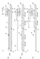
図1は、本発明を適用した実施形態に係る印刷装置1の機能ブロック図である。また、図2は印刷装置1の搬送経路に係る各部の構成を示す要部側面図である。
印刷装置1は、外部のホストPC5に接続され、ホストPC5が送信するコマンド及びデータを受信して、受信したコマンド及びデータに従って印刷媒体に文字や画像を印刷する。
Hereinafter, embodiments of the present invention will be described with reference to the drawings.
FIG. 1 is a functional block diagram of a printing apparatus 1 according to an embodiment to which the present invention is applied. FIG. 2 is a side view of the main part showing the configuration of each part related to the conveyance path of the printing apparatus 1.
The printing apparatus 1 is connected to an
印刷装置1で印刷に使用される印刷媒体は、所定サイズにカットされたカットシートまたは連続シートであり、これらのシートは紙または合成樹脂製である。これらのシートは、例えば、インクジェット式の印刷に適した、インクの吸収能および定着性を高める表面加工が施されたファイン紙であってもよい。
連続シートは、例えば、ロール状に巻かれた状態で印刷装置1に収容されるロール紙や、折りたたまれた状態で印刷装置1の外部から印刷装置1に供給されるファンフォールド紙が挙げられる。ロール紙としては、普通紙やファイン紙をロール状に巻いた用紙のほか、裏面に粘着剤が付された定型サイズのラベルを、剥離紙(台紙)に並べてロール状に巻いたラベル用紙を用いてもよい。
本実施形態では、裏面に粘着剤が付された所定サイズのラベル103(図3)が、粘着剤から剥離可能な剥離紙を長尺に形成した台紙101(図3)上に配置され、ロール状に巻かれたラベル用紙100を、印刷媒体として使用する。ラベル用紙100は、台紙101の長手方向に、複数のラベル103が等間隔で配置されて構成される。印刷装置1は、ラベル用紙100を搬送して、ラベル用紙100上の各ラベル103の印刷面に文字や画像を印刷する。この場合、ラベル用紙100は印刷媒体に相当し、ラベル103は印刷対象物に相当する。
A printing medium used for printing in the printing apparatus 1 is a cut sheet or a continuous sheet cut into a predetermined size, and these sheets are made of paper or synthetic resin. These sheets may be, for example, fine paper that has been subjected to surface treatment that is suitable for ink jet printing and that improves ink absorption and fixing properties.
Examples of the continuous sheet include roll paper accommodated in the printing apparatus 1 in a rolled state, and fanfold paper supplied to the printing apparatus 1 from the outside of the printing apparatus 1 in a folded state. As roll paper, in addition to paper that rolls plain paper or fine paper in a roll shape, a label paper that is rolled into a roll with a standard-sized label with adhesive on the back is placed on release paper (mounting paper) May be.
In the present embodiment, a label 103 (FIG. 3) having a predetermined size with a pressure-sensitive adhesive on the back surface is disposed on a base paper 101 (FIG. 3) in which a release paper that can be peeled off from the pressure-sensitive adhesive is formed in a long length. The
図2に示すように、ラベル用紙100は、印刷装置1の本体に設けられた印刷媒体収容部21にロール状で収容され、このラベル用紙100が、図中符号Fで示す方向に引き出されて印刷装置1の内部を搬送される。図2においては図中右側が、印刷装置1の前部(フロント)側となっており、印刷装置1の前面には排紙口22が形成されている。
図2にはラベル用紙100が排紙口22まで搬送される搬送経路を符号110で示す。搬送経路110には、ラベル用紙100に張力を与えて弛みを防止するテンションレバー31と、ラベル用紙100を案内する紙案内33、34とが配置される。紙案内33はラベル用紙100を下方から支持する台であり、紙案内34は、紙案内33に対向してラベル用紙100の上方に位置し、ラベル用紙100の浮き上がりを押さえる。
As shown in FIG. 2, the
In FIG. 2,
紙案内33、34の前方には、ラベル用紙100に印刷する印刷部が配置されている。印刷部は、プラテン35及び印刷ヘッド40で構成される。本実施形態の印刷ヘッド40は、C(シアン)、M(マゼンダ)、Y(イエロー)、K(黒)の4色のインクを噴射して、ラベル103の印刷面にドットを形成する。印刷ヘッド40は、K(黒)インクを噴射するノズル部41、C(シアン)インクを噴射するノズル部43、M(マゼンダ)インクを噴射するノズル部45、及び、Y(イエロー)インクを噴射するノズル部47を備える。ノズル部41〜47には、インクを噴射する複数のノズルがラベル用紙100の幅方向に列をなして並べられている。印刷ヘッド40は、ラベル用紙100の幅方向において、走査を行うことなくインクを噴射可能なラインインクジェットヘッドである。従って、ノズル部41〜47のノズル列は、少なくとも、ラベル用紙100の印刷可能範囲105(図3)と同じか、より広い幅に形成されている。本実施形態では、ラベル用紙100の搬送方向Fに沿ってノズル部41、43、45、47の順に配置された構成例を挙げるが、搬送方向Fにおける各色のノズルの配置順序は任意である。
A printing unit for printing on the
プラテン35は、搬送方向Fに沿って配置される平面を有する。この平面は搬送経路110の下方に位置して、印刷ヘッド40に対向する。プラテン35は、図示しない印刷装置1のフレームに固定され、ラベル用紙100を下方から支持する。プラテン35の平面は、印刷装置1の設置状態及び使用状態においてほぼ水平となる。
プラテン35の平面上には搬送ベルト52が配置されている。搬送ベルト52は幅広の無端形状のベルトであり、プラテン35の平面上を通り、プラテン35の下方に回り込むように配置される。搬送ベルト52の表面のうち、少なくともプラテン35の平面上で上を向く面は、摩擦係数の高い粗面となっている。搬送ベルト52はゴムや合成樹脂等の弾性材料により構成されることが好ましい。プラテン35の下方には、搬送モーター50、及び、搬送モーター50の回転力により搬送ベルト52を動かす駆動機構51が配置されている。搬送モーター50は、例えばDCモーターで構成され、後述する制御部10の制御により回転する。また、駆動機構51は、搬送モーター50の出力軸とかみ合う各種のギヤや搬送ベルト52を動かすローラー等により構成され、搬送モーター50の回転により搬送ベルト52が動いて、ラベル用紙100を搬送方向Fに搬送する。搬送モーター50の回転量または搬送モーター50の回転に伴う搬送ベルト52の移動量は、後述するロータリーエンコーダー57(図1)によって検出される。
The
A
印刷ヘッド40の上流側には、プラテン35に対向して搬送ローラー55が配置されている。搬送ローラー55は、印刷装置1のフレームに回転自在に支持される従動ローラーであり、プラテン35の平面に向けて付勢されている。搬送経路110において、ラベル用紙100は搬送ローラー55と搬送ベルト52との間に挟まれて、搬送ベルト52の移動に伴い確実に搬送方向Fに搬送される。また、印刷ヘッド40のノズル部41、43、45、47の間には、ラベル用紙100を搬送ベルト52から浮き上がらないように押さえるローラー53が配置されている。
これら搬送モーター50、駆動機構51、搬送ベルト52、ローラー53及び搬送ローラー55は、ラベル用紙100を搬送する搬送部として機能する。搬送機構は、この搬送部の一部または全部に相当する。
A
The
印刷ヘッド40の下流側、すなわち前側にはカッターユニット37が配置されている。カッターユニット37は搬送経路110を挟んで配置された固定刃38と可動刃39とを備え、可動刃39はカッター駆動モーター59(図1)にギヤ等を介して連結されている。カッター駆動モーター59が駆動すると可動刃39が固定刃38側に移動して、ラベル用紙100をカットする。カッターユニット37は、ラベル用紙100の幅方向において一部を切り残すカットをするものであってもよいし、ラベル用紙100を完全に切断するものであってもよい。印刷装置1は、カッターユニット37により、印刷ヘッド40で印刷されたラベル用紙100を所定長さにカットして、排紙口22から排出する。
A cutter unit 37 is disposed on the downstream side, that is, the front side of the
印刷装置1の前面には、排紙口22の下方に、巻取ユニット23(回収装置)が着脱可能である。巻取ユニット23は、排紙口22から排出されるラベル用紙100を巻き取る巻取ドラム25と、巻取ドラム25を回転させる図示しない駆動部とを有する。巻取ドラム25は、巻取ユニット23が備えるモーターにより駆動され、或いは、印刷装置1の搬送モーター50から図示しないギヤ列を介して伝達される回転力により、駆動される。巻取ドラム25は、図中矢印Cで示す方向に回転して、ラベル用紙100を巻き取る。巻取ユニット23が使用される場合、印刷装置1は、カッターユニット37でラベル用紙100をカットせず、ラベル用紙100を長尺の状態のまま排紙口22から排出する。例えば、印刷装置1の1回の動作で、印刷媒体収容部21に収容された1巻きのラベル用紙100の全部に印刷を施して、巻取ドラム25に巻き取ることが可能である。
A winding unit 23 (collecting device) is detachably attached to the front surface of the printing apparatus 1 below the
また、印刷装置1は、搬送経路110においてラベル用紙100を検出する2つの検出器を備えている。すなわち、紙案内34の上流部には用紙検出器61(第1の検出部)が配置され、プラテン35上において印刷ヘッド40の上流側にラベル検出器63(第2の検出部)が配置されている。用紙検出器61及びラベル検出器63は、例えば、発光部と受光部とを有する光学式のセンサーである。用紙検出器61は、例えば、紙案内34側に発光部を備え、紙案内33側に受光部を備えた透過型のセンサーである。用紙検出器61の受光量を示す出力値(検出電圧)は、用紙検出器61の位置におけるラベル用紙100の有無により異なるので、用紙検出器61を用いてラベル用紙100の先端及び後端を検出できる。また、ラベル検出器63は、例えば、プラテン35の上方に発光部と受光部とを配置した反射型のセンサーである。ラベル検出器63の受光量を示す出力値(検出電圧)は、ラベル検出器63の直下にラベル用紙100がない場合、台紙101がある場合、ラベル103がある場合の各々で異なる。すなわち、搬送ベルト52の反射光、台紙101の反射光、ラベル103の反射光の光量は、それぞれ異なっている。このため、ラベル検出器63を用いて、ラベル用紙100の先端と後端、及び、ラベル103の先端と後端を検出できる。用紙検出器61は制御部10と協働して第1の検出部として機能するということができ、ラベル検出器63も同様に、制御部10と協働して第2の検出部として機能するということができる。
Further, the printing apparatus 1 includes two detectors that detect the
図1に示すように、印刷装置1は、印刷装置1の各部を制御する制御部10を備えている。制御部10には、ホストPC5に接続されるI/F(インターフェイス)11及び記憶部12が接続されている。I/F11は、ホストPC5との間で有線または無線接続される。
制御部10は、図示しない演算実行部としてのCPU、ROM、RAM等を備えている。制御部10のROMには、CPUによって実行可能なファームウェア、ファームウェアに係るデータ等が不揮発的に記憶される。また、RAMにはCPUが実行するファームウェアに係るデータ等が一時的に記憶される。制御部10は、その他の周辺回路等を備えていてもよい。記憶部12は、各種のプログラムやデータを不揮発的に記憶する。記憶部12には、制御部10が実行する制御プログラム、これら制御プログラムに関するデータ、印刷装置1がホストPC5から受信したコマンドやデータを記憶する。
As illustrated in FIG. 1, the printing apparatus 1 includes a
The
制御部10には、スイッチパネル(図示略)に設けられた操作スイッチ60の操作を検出する操作検出部13が接続されている。操作スイッチ60は、例えば、印刷装置1の搬送動作を指示する紙送りスイッチ、カッターユニット37の動作を指示するカットスイッチ、各種設定を行う設定用スイッチ等である。
また、制御部10には、用紙検出器61及びラベル検出器63の検出値を取得するセンサー駆動部14、15が接続されている。センサー駆動部14は、用紙検出器61に駆動用の電力を供給して発光させ、用紙検出器61が受光量に応じて出力する検出電圧を取得して、検出電圧を示す検出値を制御部10に出力する。センサー駆動部15は、ラベル検出器63に駆動用の電力を供給して発光させ、ラベル検出器63が受光量に応じて出力する検出電圧を取得して、検出電圧を示す検出値を制御部10に出力する。
The
In addition,
また、制御部10には、ラベル用紙100の搬送量をカウントするカウンター回路16が接続される。カウンター回路16は、搬送部の動作量、すなわち、搬送ベルト52の移動量や搬送モーター50の回転量、搬送ローラー55の回転量等を検出するロータリーエンコーダー57に接続される。カウンター回路16は、制御部10の制御に従って、ロータリーエンコーダー57が出力するパルスをカウントし、カウント値を制御部10に出力する。
The
制御部10には、搬送モーター50及びカッター駆動モーター59を駆動するモータードライバー17、及び、印刷ヘッド40を駆動するヘッドドライバー18が接続される。モータードライバー17は、制御部10の制御に従って、搬送モーター50及びカッター駆動モーター59の各々に駆動電流を供給する。また、モータードライバー17は、例えばカッター駆動モーター59がステッピングモーターで構成される場合、カッター駆動モーター59に駆動パルスを出力して動作量を制御する。
ヘッドドライバー18は、印刷ヘッド40にインクタンク(図示略)からインクを供給するポンプ(図示略)や、印刷ヘッド40のノズル部41〜47に設けられたピエゾ素子(図示略)に電圧を供給して、これらを動作させる。これにより、ノズル部41〜47の各ノズルからインク滴が吐出されてドットが形成される。
A
The
図3は、ラベル用紙100の搬送経路110における各部の位置関係を示す説明図である。図3(A)は平面図であり、図3(B)は側面視図であり、(A)と(B)では搬送方向Fにおける位置を対応させて示す。この図3には、後述するようにラベル用紙100の終端100Aが用紙検出器61により検出されたときの状態を示している。
図3(A)及び(B)には、印刷ヘッド40のノズル部41、43、45、47(図1)が備えるノズル列42、44、46、48を示す。ノズル列42はノズル部41のノズルがラベル用紙100の幅方向に並んだ列である。本実施形態では、ノズル部41、43、45、47がそれぞれ2列のノズル列を備えた構成を例示する。すなわち、印刷ヘッド40は、搬送方向Fの上流側から順に、Kインクを吐出する2列のノズル列42、Cインクを噴射する2列のノズル列44、Mインクを噴射する2列のノズル列46、及び、Yインクを噴射する2列のノズル列48を備えている。
FIG. 3 is an explanatory diagram showing the positional relationship of each part in the
3A and 3B show
上述のように、ラベル用紙100は台紙101にラベル103が等間隔で並べて配置された構成となっている。印刷装置1は、各ラベル103の長さの指標として論理ラベル長L1を記憶している。論理ラベル長L1は、予め操作スイッチ60の操作やホストPC5から印刷装置1にコマンドを送信することにより設定され、記憶部12または制御部10が内蔵するROMに、制御部10が読み取り可能なデータ形式で記憶される。論理ラベル長L1は、搬送方向Fにおける長さであり、実際のラベル103の長さであるラベル長L2と、ラベル103とラベル103との間隔であるギャップ長L3とを合計した長さである。つまり、論理ラベル長L1は、ラベル103の先端から次のラベル103の先端までの長さである。
As described above, the
ラベル103において文字や画像等の印刷が可能な範囲を、印刷可能範囲105として破線で示す。印刷可能範囲105はノズル列42〜48の幅方向のサイズを含む印刷装置1の仕様とラベル103のサイズ等により決定される。印刷可能範囲105の長さを印刷可能長L4とする。印刷可能長L4の長さは、論理ラベル長L1と同様に印刷装置1に設定され、記憶される。また、印刷可能長L4とともに、印刷装置1には、ラベル用紙100の幅、ラベル103の幅、印刷可能範囲105の幅等が予め設定され、記憶されていてもよい。
さらに、図3(A)に、印刷ヘッド40によりラベル103に印刷される文字や画像を印刷画像107として示し、印刷画像107の長さを印刷長L10とする。印刷長L10は、制御部10が、ホストPC5から受信する印刷データに基づき求めることができる。ラベル103の先端から印刷画像107の先端までの余白部分の長さを印刷データオフセットL11とする。
また、ラベル用紙100においては、ラベル103が終端100A近くまで配置されており、最終のラベル103の末端と終端100Aとの間には、長さL6(余白長)の余白が設けられている。余白長L6は通常、論理ラベル長L1やラベル長L2に比べて短く、本実施形態ではギャップ長L3が余白長L6と等しいものとする。また、ラベル用紙100が本来の長さより短く切られている場合には、余白が存在しないことがある。
A range in which characters and images can be printed on the
Further, FIG. 3A shows a character or image printed on the
Further, in the
図3(A)及び(B)には、印刷装置1の搬送方向Fにおける複数の位置P1〜P6、P10を示す。これらの位置P1〜P6、P10は、制御部10がラベル用紙100の搬送及び印刷を制御する場合に基準となる。
位置P1は、用紙検出器61の検出位置である。図3に示すように、ラベル用紙100の終端(末端)100Aが検出位置P1を通過する際に、用紙検出器61の検出値が変化する。制御部10は、この用紙検出器61の検出値の変化に基づき、検出位置P1に終端100Aが達したことを検出する。制御部10は、用紙検出器61により終端100Aを検出した後は、カウンター回路16のカウント値の増加量に基づいて搬送量を算出することにより、終端100Aの位置を常に特定できる。
3A and 3B show a plurality of positions P1 to P6 and P10 in the transport direction F of the printing apparatus 1. FIG. These positions P <b> 1 to P <b> 6 and P <b> 10 serve as a reference when the
The position P1 is a detection position of the
位置P2は、ラベル検出器63の検出位置である。ラベル103の先端または後端が検出位置P2を通過する際に、ラベル検出器63の検出値が変化する。制御部10は、ラベル検出器63の検出値の変化に基づき、ラベル103の先端または後端が検出位置P2に達したことを検出する。本実施形態では、印刷装置1はラベル検出器63によりラベル103の先端を検出する。ラベル103の終端は、例えば、ラベル103の先端に論理ラベル長L1を加えることで求めることができる。
位置P3は、印刷ヘッド40が有するノズル列のうち最も上流側に位置するノズル列42の位置である。
位置P4は、印刷ヘッド40が有するノズル列のうち最も下流側に位置するノズル列48の位置である。ラベル103の終端が位置P4に達すると、当該ラベル103への印刷が完了するので、以下ではP4を印刷最終位置P4と呼ぶ。制御部10は、位置P4からの長さを比較することにより、ラベル103に対して最後まで印刷を完了できるか否か判定する。すなわち、位置P4を基準位置として判定を行う。
The position P2 is a detection position of the
The position P3 is the position of the
The position P4 is the position of the
位置P5は、カッターユニット37がラベル用紙100をカットするカット位置である。カッターユニット37によりラベル用紙100をカットしないで、ラベル用紙100がカット位置P5を通過する動作をさせることも勿論可能である。
The position P5 is a cutting position where the cutter unit 37 cuts the
位置P6は、巻取ユニット23を使用する場合に、印刷ヘッド40による印刷を完了するために必要なラベル用紙100の最小限の長さに対応する位置である。以下では保持限界位置P6と呼ぶ。巻取ユニット23を使用する場合、ラベル用紙100には巻取ドラム25に巻き取る力が加わるので、この力に対抗してラベル用紙100を保持する必要がある。印刷装置1は、搬送ローラー55と搬送ベルト52とでラベル用紙100を挟み、巻取ユニット23の引っ張り力に対抗する。保持限界位置P6は、ラベル103の印刷が完了するまで搬送ローラー55がラベル用紙100を把持できるか否かを判定する指標である。終端100Aが保持限界位置P6の位置、または位置P6より上流側にあれば、巻取ユニット23の引っ張り力に抗してラベル用紙100を正常に搬送できる。また、終端100Aが保持限界位置P6より下流になると、巻取ユニット23の引っ張り力によりラベル用紙100が引き出され、正常な印刷ができない。
The position P6 is a position corresponding to the minimum length of the
印刷装置1では、搬送経路110に配置された機械的構造により、ラベル103を設定された速度で搬送するために必要なラベル用紙100の長さ等が決まっている。ラベル用紙100の残りの長さが短い場合、終端100Aの近くのラベル103への印刷を完了できないことがある。印刷を完了できないラベル103は使用されず破棄されるので、インク等の消費材や時間の無駄を抑えるため、印刷を完了できないラベル103は印刷せずに排出し、ロールを交換することが望ましい。
そこで、印刷装置1の制御部10は、最も上流側に位置する用紙検出器61によって終端100Aが検出された場合に、ラベル検出器63で検出したラベル103について、印刷可能か否かを判定する。そして、印刷可能でないラベル103に対して不要な印刷を行わないように制御する。
In the printing apparatus 1, the length of the
Therefore, the
ラベル103が印刷可能でない場合とは、ラベル103の印刷完了までラベル103を設定された所定の搬送速度で搬送できない場合や、および、ラベル103の末端が切られている場合等が該当する。
The case where the
ラベル103の最後まで正常に印刷を実行するためには、巻取ユニット23を使用して印刷する場合、上記のように、印刷完了まで終端100Aが保持限界位置P6またはそれより上流に位置している必要がある。これに対し、巻取ユニット23を使用しないで印刷する場合、印刷完了までローラー53及び搬送ベルト52でラベル用紙100を保持できればよく、印刷完了まで終端100Aが位置P4より上流にあればよい。
In order to perform printing normally until the end of the
制御部10は、印刷が完了できるか否かの判定をするため、最終印刷位置P4から終端100Aまでの長さLAを用いる。制御部10は、用紙検出器61により終端100Aが検出されたときに、長さLAを、最終印刷位置P4から検出位置P1までの距離に設定する。その後、制御部10は、ラベル用紙100の搬送に伴って長さLAを減算する。
また、各々のラベル103について印刷を完了できるか否かを判定するため、制御部10は、各ラベル103の先端から最終印刷位置P4までの長さLBを用いる。図3の例では、例えばラベル103Bについては、最終印刷位置P4から位置P10までの距離が、長さLBである。制御部10は、ラベル103の先端がラベル検出器63により検出されたときに、検出されたラベル103について、長さLBを、最終印刷位置P4から検出位置P2までの距離に設定する。その後、制御部10は、ラベル用紙100の搬送に十成って長さLBを減算する。
巻取ユニット23を用いる場合、最終印刷位置P4から保持限界位置P6までの距離LCを判定の基準に用いる。 検出位置P1、P2、最終印刷位置P4、保持限界位置P6の位置、及び、各位置間の距離(例えば、距離LC)は印刷装置1の機械的構造により決定され、予め印刷装置1に設定され、制御部10が参照可能なデータとして記憶されている。
The
Further, in order to determine whether printing can be completed for each
When the winding
ここで、制御部10がラベル103について印刷可能か否かを判定する処理について説明する。
制御部10は、ラベル検出器63によってラベル103の先端を検出すると、ラベル103の先端から最終印刷位置P4までの長さLBを設定する。長さLBは、ラベル検出器63が検出しラベル103毎に、個別に設定され、ラベル用紙100の搬送に伴い減算される。
制御部10は、用紙検出器61により終端100Aを検出すると、長さLAを設定し、長さLAと、検出された各ラベル103の長さLBとに基づき、既に検出されたラベル103について最後まで印刷を完了できるか否かを判定する。
Here, processing for determining whether the
When the
When the
判定の基準は、巻取ユニット23を用いるか否かにより異なる。
巻取ユニット23を用いない場合、ラベル103の終端が最終印刷位置P4に達した時点で、終端100Aが位置P4より上流にあればよい。詳細には、終端100Aが最終印刷位置P4に位置していてもよい。
ラベル103の終端が最終印刷位置P4に達するまでの搬送量は、下記式(1)により求められる。
搬送量=長さLB+論理ラベル長L1 …(1)
印刷を完了するためには、ラベル用紙100の残りの長さLAが上記式(1)で求められる搬送量以上であればよい。即ち、下記式(2)の関係が成立すればよい。
長さLA≧長さLB+論理ラベル長L1 …(2)
制御部10は、上記式(2)の関係が成立するか否かにより、ラベル103の印刷を完了できるか否かを判定できる。
The criterion for determination varies depending on whether or not the winding
When the winding
The conveyance amount until the end of the
Carrying amount = length LB + logical label length L1 (1)
In order to complete the printing, the remaining length LA of the
Length LA ≧ length LB + logical label length L1 (2)
The
一方、巻取ユニット23を用いる場合、ラベル103の終端が最終印刷位置P4に達した時点で、終端100Aが保持限界位置P6、またはその上流にあればよい。
ラベル103の終端が最終印刷位置P4に達するまでの搬送量は、上記式(1)により求められる。
印刷を完了するためには、ラベル用紙100の残りの長さLAが、上記式(1)で求められる搬送量に、最終印刷位置P4から保持限界位置P6までの距離LCを加えた長さ以上であればよい。即ち、下記式(3)の関係が成立すればよい。
長さLA≧長さLB+論理ラベル長L1+距離LC …(3)
制御部10は、上記式(3)の関係が成立するか否かにより、ラベル103の印刷を完了できるか否かを判定できる。
On the other hand, when the winding
The conveyance amount until the end of the
In order to complete the printing, the remaining length LA of the
Length LA ≧ length LB + logical label length L1 + distance LC (3)
The
上記式(3)において距離LCをゼロとすれば式(2)が得られる。つまり、巻取ユニット23を使用しない場合は、ラベル103の末端から最終印刷位置P4までの必要長さがゼロであるため、式(2)となる。従って、上記式(2)、(3)は、下記式(4)に書き換えることができる。
長さLA≧長さLB+論理ラベル長L1+残り必要長さ …(4)
上記式において、残り必要長さは、ラベル103の末端から最終印刷位置P4までの必要な長さを示し、式(2)ではゼロ、式(3)では距離LCとなる。
なお、長さLAと長さLBは、ラベル用紙100の搬送に伴って同じように減算され、残り必要長さは固定値である。従って、上記式(4)に基づく判定を行うタイミングは制限されない。制御部10は、判定対象のラベル103の先端がラベル検出器63により検出され、かつ、終端100Aが用紙検出器61により検出された後であれば、いつでも判定できる。
If the distance LC is set to zero in the above formula (3), formula (2) is obtained. That is, when the winding
Length LA ≧ length LB + logical label length L1 + remaining required length (4)
In the above equation, the remaining necessary length indicates the necessary length from the end of the
Note that the length LA and the length LB are similarly subtracted with the conveyance of the
図4は、印刷装置1の動作を示すフローチャートである。
制御部10は、ホストPC5から印刷コマンドと印刷データを受信して印刷動作を開始し(ステップS11)、印刷実行前に記憶部12またはROMから、印刷媒体収容部21のラベル用紙100の論理ラベル長L1を取得する(ステップS12)。
制御部10は、印刷中に、ラベル検出器63によりラベル103の先端が検出されたか否かを監視する(ステップS13)。ラベル103が検出された場合(ステップS13;Yes)、制御部10は、検出されたラベル103の先端位置を検出位置P2として長さLBを設定し、長さLBの減算を開始する(ステップS14)。
なお、制御部10は、ラベル用紙100を搬送する間は長さLBを減算し続け、例えば長さLBがゼロになると、そのラベル103について長さLBをクリアする。続いて、制御部10は、用紙検出器61により終端100Aが検出されたか否かを監視する(ステップS15)。終端100Aが検出されなければ(ステップS13;No)、制御部10はステップS13に戻ってラベル103の検出の監視を継続する。この間、制御部10は印刷を継続している。また、ラベル検出器63によりラベル103が検出されない間は(ステップS13;No)、ステップS14の処理を行わずにステップS15に移行する。
FIG. 4 is a flowchart showing the operation of the printing apparatus 1.
The
The
The
用紙検出器61により終端100Aが検出されると(ステップS15;Yes)、制御部10は、ラベル用紙100の残り長さLAを設定する(ステップS16)。ここで設定された長さLAは上記のように減算される。制御部10は、既にラベル検出器63により検出されて長さLBが設定されたラベル103について、印刷可能範囲105の最後まで印刷が可能か否かの判定を開始する(ステップS17)。本実施形態では便宜的に、ラベル103の終端まで印刷が可能か否かを判定する。また、以下の処理では、既に印刷が完了したラベル103、すなわち長さLBがクリアされたラベル103については判定しない。
When the
制御部10は、巻取ユニット23を使用しているか否かを判別する(ステップS18)。印刷装置1は、巻取ユニット23を使用するか否かを制御部10が特定可能な構成となっている。例えば、ホストPC5から印刷装置1にコマンドを送信することにより、巻取ユニット23の使用/不使用を設定してもよい。また、印刷装置1の前面において巻取ユニット23が装着される位置に、巻取ユニット23の装着時に機械的に動作するセンサーを配置し、このセンサーの検出状態により巻取ユニット23の有無を検出する構成としてもよい。
The
巻取ユニット23を使用している場合(ステップS18;Yes)、制御部10は、巻取ユニット23使用時の必要長さの設定値を取得する(ステップS19)。具体的には、制御部10は距離LCの値を、記憶部12から取得する。また、巻取ユニット23を使用していない場合(ステップS18;No)、制御部10は、巻取ユニット23非使用時の必要長さの設定値を取得する(ステップS20)。本実施形態では、巻取ユニット23非使用時の必要長さの設定値はゼロである。
ステップS19、S20の後、制御部10は、取得した必要長さの設定値、ステップS14で設定した長さLB、及び、ステップS16で設定したラベル用紙100の残り長さLAに基づき、上記式(4)の演算を行う(ステップS21)。
When the winding
After steps S19 and S20, the
制御部10は、上記式(4)の比較演算により、ラベル103の印刷が可能か否かを判定する(ステップS22)。ステップS21〜S22で、判定する対象のラベル103が複数存在する場合、制御部10は、下流側のラベル103から順に判定する。
ラベル検出器63で検出済みの全てのラベル103の印刷が可能な場合(ステップS22;Yes)、制御部10は、次のラベル103がラベル検出器63により検出されるまでラベル検出器63の検出値を監視する(ステップS23)。ラベル103が検出されない間(ステップS23;No)、制御部10は、終端100Aが最終印刷位置P4まで搬送されたか否かを監視する(ステップS24)。すなわち、終端100Aまでの残り長さLAがゼロになったか否かを判定し、長さLAがゼロでない場合は(ステップS24;No)ステップS23に戻る。また、長さLAがゼロになった場合(ステップS24;Yes)、制御部10は、ラベル用紙100を排紙口22から排出して(ステップS25)、その後にホストPC5に対して印刷完了を通知して(ステップS26)、本処理を終了する。
The
When printing of all
また、ラベル検出器63によりラベル103が検出された場合(ステップS23;Yes)、制御部10は、このラベル103に対し長さLBを設定して、ステップS21に戻る。
一方、ラベル検出器63で検出されたいずれかのラベル103の印刷が不可能であると判定した場合(ステップS22;No)、制御部10は、印刷が可能であると判定されたラベル103について印刷が完了するまで印刷を継続する(ステップS27)。その後、印刷が不可能であると判定されたラベル103の印刷をしないうちに印刷動作を停止し(ステップS28)、ステップS25に移行してラベル用紙100を排出する。なお、ステップS22において印刷できないと判定したラベル103に対する印刷が、既に開始されている場合には、制御部10はステップS27で印刷を速やかに中断し、ステップS25に移行する。
When the
On the other hand, when it is determined that printing of any
図5〜図6は、印刷装置1の動作の具体例を示す説明図である。
図5(A)、図5(B)、図5(C)及び図6には、ラベル103の長さ等が異なる様々な例を示す。
図5(A)は論理ラベル長L1が長いラベル103を印刷する例を示す。図5(A)の例では、ラベル検出器63によりラベル103の先端が検出された後、用紙検出器61により終端100Aが検出された時点で、ラベル103の先端が最終印刷位置P4に近い位置にある。この場合、制御部10は、終端100Aが検出されると、図4のステップS21〜S22で印刷可能か否かを判定する。図5(A)の例では、上記式(4)で説明したように、巻取ユニット23を使用しない場合は印刷を完了でき、巻取ユニット23を使用する場合は印刷を完了できない。印刷を完了できない場合、制御部10はラベル103に印刷せず排紙するので、インクの無駄を防止できる。
5 to 6 are explanatory diagrams illustrating specific examples of the operation of the printing apparatus 1.
5A, 5B, 5C, and 6 show various examples in which the length of the
FIG. 5A shows an example of printing a
図5(B)の例では長さLAに対して短い多数のラベル103が、ラベル用紙100に並んでいる。図5(B)に示すように、用紙検出器61により終端100Aが検出された時点で、制御部10は、既にラベル検出器63により検出されたラベル103(ラベル103A、103B)について、印刷可能であるか否かを判定する。例えば、ラベル103Bの印刷ができないと判定した場合、制御部10は、ラベル103Aの印刷を完了した後でラベル用紙100を排紙する。この場合、印刷できないラベル103Bに印刷を行わないので、インクの無駄を防止できる。さらに、ラベル103Bの後に位置するラベル103C、103Dについては印刷の可否の判定を行わないので、効率よく処理できる。
In the example of FIG. 5B, a large number of
図5(C)の例では終端100Aに近いラベル103Bが切断されている。このような場合も、ラベル用紙100の残り長さLAと、各ラベル103について設定された長さLBとを上記式(4)に基づき比較することで、印刷の可否を適切に判定できる。図5(C)の例では、末端が切断されたことにより、ラベル用紙100の残り長さLAが短くなる。これに対し、ラベル103Bの長さLBは、ラベル103Bの末端側が切られていても変化しない。このため、ラベル103Bについては印刷できないと判定される。なお、制御部10は、ラベル用紙100の残り長さLAと論理ラベル長L1とを比較することで、ラベル103が切られているか否かを判定することが可能である。ラベル103が切られていると判定した場合、制御部10は、そのラベル103については式(4)の演算を行わずに印刷できないと判定してもよい。
In the example of FIG. 5C, the
図6は、ラベル用紙100の末端近くに位置するラベル103について、印刷できないと判定した場合に、その前のラベル103Aが印刷中である例を示す。このような場合、図4のステップS27で説明したように、制御部10は、ラベル103Aの印刷が完了してから、印刷を停止して排紙する。
FIG. 6 shows an example in which the
以上説明したように、本発明を適用した実施形態に係る印刷装置1は、印刷対象部であるラベル103を有するラベル用紙100を搬送する搬送機構と、ラベル103に印刷する印刷ヘッドとを備える。また、印刷装置1は、搬送経路でラベル用紙100の終端100Aを検出する用紙検出器61、及び、ラベル103を検出するラベル検出器63を備える。制御部10は、用紙検出器61により検出される終端100Aの位置に基づき、ラベル検出器63により検出されるラベル103への印刷を完了できるか否かを判定する。そして、制御部10は、印刷を完了できないと判定した場合に、当該ラベル103への印刷を中止または回避する。例えば、印刷を完了できないと判定したラベル103が既に印刷中であれば印刷を中断し、まだ印刷されていなければ印刷せず排紙する。これにより、ラベル103の印刷を完了できない場合に印刷を中止または回避するので、不要な印刷動作を抑制でき、印刷に要する消費材や時間の無駄を省くことができる。
As described above, the printing apparatus 1 according to the embodiment to which the present invention is applied includes the transport mechanism that transports the
また、制御部10は、用紙検出器61により終端100Aが検出される前にラベル検出器63により検出されたラベル103について、用紙検出器61により終端100Aが検出された後に印刷の可否を判定する。このため、用紙検出器61が終端100Aを検出する前にラベル検出器63の検出位置を通過してしまったラベル103についても、印刷の可否を判定できる。
また、ラベル用紙100には、複数の所定長さのラベル103が搬送方向に沿って並べて配置され、制御部10は、印刷を完了できないと判定したラベル103よりも上流側に位置する他のラベル103について判定を行わない。このため、印刷を完了できないラベル103があった場合、その後に印刷される予定のラベル103については判定をせず、速やかに印刷以外の動作を実行できる。例えば、ラベル用紙100の残り長さの不足により印刷を完了できないラベル103があった場合、それよりも後に印刷されるラベル103は、印刷できないことが明らかである。このような場合、判定を行わないことで、処理の効率化を図ることができる。また、正常に印刷されないラベル103があった場合に速やかに排出するなど、効率よくラベル用紙100を処理できる。
Further, the
In addition, a plurality of
また、制御部10は、ラベル103への印刷の可否を判定する処理において、終端100Aの位置に基づき、ラベル103への印刷が完了するまでラベル用紙100を搬送可能かを判定する。このため、ラベル用紙100の残り長さが不足する場合に、速やかに、印刷を完了できないと判定でき、ラベル103への印刷の可否を適切に判定できる。
また、制御部10は、ラベル103への印刷が完了するまでラベル用紙100を搬送するのに必要なラベル用紙100の残り長さの設定値に基づき、判定を行う。ラベル用紙100の残り長さの設定値は、例えば、上述した残り必要長さである。制御部10は、予め設定され記憶部12に記憶された値に基づき、ラベル103への印刷の可否を適切に判定できる。
また、印刷装置1は、印刷ヘッドよりも下流側に、印刷後のラベル用紙100を回収する巻取ユニット23を装着可能である。実施形態では排紙口22に巻取ユニット23を取り付けることができる。制御部10は、巻取ユニット23の装着の有無に対応するラベル用紙100の残り必要長さの設定値に基づき、判定を行う。これにより、巻取ユニット23の有無による影響を加味して、ラベル103への印刷の可否を適切に判定できる。
Further, in the process of determining whether or not printing on the
Further, the
Further, the printing apparatus 1 can be equipped with a winding
なお、上述した実施の形態は、あくまでも本発明の一態様を示すものであり、本発明の範囲内で任意に変形および応用が可能である。
例えば、上述した実施形態では、搬送経路110に設けたラベル検出器63によって、ラベル103の先端を検出する例について説明した。本発明はこれに限定されず、例えば、ラベル検出器63により、ラベル用紙100に付されたブラックマークを検出してもよいし、ブラックマークを検出するための光センサーを、ラベル検出器63とは別に設けてもよい。ブラックマークは、ラベル用紙100におけるラベル103の位置を示す黒色または濃色のマークであり、ラベル用紙100の表面に付されていても裏面に付されていてもよい。ラベル検出器63、または追加の光センサーは、ブラックマークの位置に対応して、搬送経路110の上方に設けられていても、下方に設けられていてもよい。
また、印刷装置1が印刷したラベル用紙100を回収する回収装置として、巻取ユニット23を例に挙げて説明したが、回収装置は、印刷装置1の排紙口22から排出されるラベル用紙100を回収可能であればよく、具体的構成は任意である。例えば、排紙口22の外でラベル用紙100を把持するローラーと、ラベル用紙100を折りたたんだ状態や丸めた状態で収容する収容部とを備える回収装置を設けてもよい。
The above-described embodiment is merely an aspect of the present invention, and can be arbitrarily modified and applied within the scope of the present invention.
For example, in the above-described embodiment, the example in which the leading end of the
Further, although the winding
また、上記実施形態では、ホストPC5から受信した印刷データに基づいて印刷装置1が印刷を行う構成を例に挙げて説明したが、印刷装置1は、内蔵する画像データや文字データ等を印刷するスタンドアロンのプリンターであってもよい。また、上記実施形態ではインクジェット式プリンターを例に挙げて説明したが、印刷装置1の構成は特に限定されず、ドットインパクト式プリンター、サーマルプリンター、レーザープリンター等にも適用できる。また、図1に示す各機能ブロックはハードウェアとソフトウェアの協働により任意に実現可能であり、特定のハードウェア構成を示唆するものではない。また、制御部10は、印刷装置1に外部接続される記憶媒体に記憶させたプログラムを実行することにより、各種動作を実行してもよい。
In the above embodiment, the configuration in which the printing apparatus 1 performs printing based on the print data received from the
1…印刷装置、10…制御部、12…記憶部、13…操作検出部、14、15…センサー駆動部、21…印刷媒体収容部、22…排紙口、23…巻取ユニット(回収装置)、35…プラテン、37…カッターユニット、40…印刷ヘッド、50…搬送モーター、61…用紙検出器(第1の検出部)、63…ラベル検出器(第2の検出部)、100…ラベル用紙(印刷媒体)、103…ラベル(印刷対象部)、110…搬送経路。 DESCRIPTION OF SYMBOLS 1 ... Printing apparatus, 10 ... Control part, 12 ... Memory | storage part, 13 ... Operation detection part, 14, 15 ... Sensor drive part, 21 ... Print medium accommodating part, 22 ... Paper discharge port, 23 ... Winding unit (collection apparatus) , 35... Platen, 37... Cutter unit, 40... Print head, 50... Transport motor, 61... Paper detector (first detector), 63 ... Label detector (second detector), 100. Paper (printing medium), 103... Label (print target part), 110.
Claims (6)
前記印刷対象部に印刷する印刷ヘッドと、
前記印刷媒体の搬送経路で前記印刷媒体の終端を検出する第1の検出部と、
前記搬送経路で前記印刷対象部を検出する第2の検出部と、
前記第1の検出部により検出される前記印刷媒体の終端の位置に基づき、前記第2の検出部により検出される前記印刷対象部への印刷を完了できるか否かを判定し、前記印刷対象部への印刷を完了できないと判定した場合に、前記印刷ヘッドを制御して当該印刷対象部への印刷を中止する、または当該印刷対象部への印刷を行わない制御部と、を備え、
前記制御部は、
前記第1の検出部により前記印刷媒体の終端が検出される前に前記第2の検出部により検出された前記印刷対象部の前記搬送経路における位置情報を保持し、
前記第1の検出部により前記印刷媒体の終端が検出された後に、検出された前記印刷媒体の終端の位置、及び保持される前記印刷対象部の前記位置情報に基づき、前記印刷対象部への印刷を完了できるか否か判定すること、を特徴とする印刷装置。 A transport mechanism for transporting a print medium having a print target portion;
A print head for printing on the print target portion;
A first detection unit that detects an end of the print medium in a conveyance path of the print medium;
A second detection unit for detecting the print target unit in the conveyance path;
Based on the end position of the print medium detected by the first detection unit, it is determined whether printing on the print target unit detected by the second detection unit can be completed, and the print target A control unit that controls the print head to stop printing on the print target part or not to print on the print target part when it is determined that printing on the part cannot be completed,
The controller is
Holding position information in the transport path of the print target portion detected by the second detection portion before the end of the print medium is detected by the first detection portion;
After termination of the printing medium is detected by the first detector, the position of the end of said detected print media, and on the basis of the position information of the printed portion to be retained, to the printed portion And determining whether or not printing can be completed.
前記制御部は、前記第1の印刷対象部への印刷を完了できないと判定した場合、前記第2の印刷対象部への印刷を完了できるか否かの判定を行わないこと、を特徴とする請求項1記載の印刷装置。 The print medium includes a first print target part, and a second print target part located upstream of the first print target part in the transport direction of the print medium,
When the control unit determines that printing on the first print target unit cannot be completed, the control unit does not determine whether printing on the second print target unit can be completed. The printing apparatus according to claim 1 .
前記印刷対象部に印刷する印刷ヘッドと、A print head for printing on the print target portion;
前記印刷媒体の搬送経路で前記印刷媒体の終端を検出する第1の検出部と、A first detection unit that detects an end of the print medium in a conveyance path of the print medium;
前記搬送経路で前記印刷対象部を検出する第2の検出部と、A second detection unit for detecting the print target unit in the conveyance path;
前記第1の検出部により検出される前記印刷媒体の終端の位置に基づき、前記第2の検出部により検出される前記印刷対象部への印刷を完了できるか否かを判定し、前記印刷対象部への印刷を完了できないと判定した場合に、前記印刷ヘッドを制御して当該印刷対象部への印刷を中止する、または当該印刷対象部への印刷を行わない制御部と、を備え、Based on the end position of the print medium detected by the first detection unit, it is determined whether printing on the print target unit detected by the second detection unit can be completed, and the print target A control unit that controls the print head to stop printing on the print target part or not to print on the print target part when it is determined that printing on the part cannot be completed,
前記搬送経路で前記印刷ヘッドよりも下流側に、印刷後の前記印刷媒体を回収する回収装置が装着可能であり、A recovery device that recovers the print medium after printing can be attached to the downstream side of the print head in the transport path,
前記制御部は、前記印刷対象部への印刷が完了するまで前記印刷媒体を搬送するのに必要な前記印刷媒体の残り長さとして設定された設定値に基づき、前記印刷対象部への印刷を完了できるか否かを判定し、The control unit performs printing on the print target unit based on a setting value set as a remaining length of the print medium necessary for conveying the print medium until printing on the print target unit is completed. Determine if it can be completed,
前記回収装置の装着の有無に対応する前記設定値に基づき、判定を行うことを特徴とする印刷装置。A printing apparatus that performs determination based on the set value corresponding to whether or not the collecting apparatus is attached.
前記印刷媒体の搬送経路で前記印刷媒体の終端及び前記印刷対象部を検出する検出ステップと、
検出ステップにより検出される前記印刷媒体の終端の位置に基づき、検出される前記印刷対象部への印刷を完了できるか否かを判定する判定ステップと、を有し、
前記判定ステップは、前記印刷媒体の終端が検出される前に検出された前記印刷対象部の前記搬送経路における位置情報を保持し、
前記印刷媒体の終端が検出された後に、検出された前記印刷媒体の終端の位置、及び保持される前記印刷対象部の前記位置情報に基づき、前記印刷対象部への印刷を完了できるか否か判定し、
前記印刷対象部への印刷を完了できないと判定した場合に、当該印刷対象部への印刷を中止する、または当該印刷対象部への印刷を行わないこと、
を特徴とする印刷装置の制御方法。 When transporting and printing a print medium having a print target part,
A detection step of detecting an end of the print medium and the print target portion in a conveyance path of the print medium ;
Based on the position of the end of the printing medium detected by the detecting step includes a determination step of determining whether it can complete the printing on the print target portion to be detected, and
The determination step holds position information on the transport path of the print target portion detected before the end of the print medium is detected,
Whether or not printing on the print target part can be completed based on the detected position of the end of the print medium and the position information of the held print target part after the end of the print medium is detected Judgment,
When it is determined that printing on the print target part cannot be completed, printing on the print target part is stopped, or printing on the print target part is not performed,
A control method for a printing apparatus.
Priority Applications (3)
| Application Number | Priority Date | Filing Date | Title |
|---|---|---|---|
| JP2014026367A JP6299258B2 (en) | 2014-02-14 | 2014-02-14 | Printing apparatus and printing apparatus control method |
| US14/486,812 US9132674B2 (en) | 2013-09-27 | 2014-09-15 | Printer and control method of a printer |
| CN201410486523.1A CN104512107B (en) | 2013-09-27 | 2014-09-22 | Printing equipment and the control method of printing equipment |
Applications Claiming Priority (1)
| Application Number | Priority Date | Filing Date | Title |
|---|---|---|---|
| JP2014026367A JP6299258B2 (en) | 2014-02-14 | 2014-02-14 | Printing apparatus and printing apparatus control method |
Publications (3)
| Publication Number | Publication Date |
|---|---|
| JP2015150774A JP2015150774A (en) | 2015-08-24 |
| JP2015150774A5 JP2015150774A5 (en) | 2017-03-23 |
| JP6299258B2 true JP6299258B2 (en) | 2018-03-28 |
Family
ID=53893535
Family Applications (1)
| Application Number | Title | Priority Date | Filing Date |
|---|---|---|---|
| JP2014026367A Active JP6299258B2 (en) | 2013-09-27 | 2014-02-14 | Printing apparatus and printing apparatus control method |
Country Status (1)
| Country | Link |
|---|---|
| JP (1) | JP6299258B2 (en) |
Families Citing this family (1)
| Publication number | Priority date | Publication date | Assignee | Title |
|---|---|---|---|---|
| JP6981107B2 (en) * | 2017-08-30 | 2021-12-15 | セイコーエプソン株式会社 | Printing device and control method of printing device |
Family Cites Families (9)
| Publication number | Priority date | Publication date | Assignee | Title |
|---|---|---|---|---|
| JP2003048364A (en) * | 2001-08-06 | 2003-02-18 | Canon Aptex Inc | Method for detecting end of recording medium and recorder |
| JP5063317B2 (en) * | 2007-11-29 | 2012-10-31 | 株式会社サトー知識財産研究所 | Printer |
| JP2010012660A (en) * | 2008-07-02 | 2010-01-21 | Canon Inc | Recorder |
| CN101722746B (en) * | 2009-12-17 | 2011-09-28 | 山东新北洋信息技术股份有限公司 | Printer as well as paper-accommodating assembly and paper-used up detection mechanism thereof |
| JP2013063834A (en) * | 2011-09-20 | 2013-04-11 | Seiko Epson Corp | Printing apparatus, and control method thereof |
| CN103358715B (en) * | 2012-03-30 | 2016-12-14 | 山东新北洋信息技术股份有限公司 | The recognition methods of paper delivery module, paper delivery module, printer and print system |
| JP2014008724A (en) * | 2012-07-02 | 2014-01-20 | Seiko Epson Corp | Label printer and control method for the same |
| JP5609999B2 (en) * | 2013-01-16 | 2014-10-22 | セイコーエプソン株式会社 | Printer reprint control method and printer |
| CN103434277B (en) * | 2013-08-22 | 2016-12-28 | 重庆品胜科技有限公司 | A kind of label width of handheld label printer measuring method |
-
2014
- 2014-02-14 JP JP2014026367A patent/JP6299258B2/en active Active
Also Published As
| Publication number | Publication date |
|---|---|
| JP2015150774A (en) | 2015-08-24 |
Similar Documents
| Publication | Publication Date | Title |
|---|---|---|
| US9132674B2 (en) | Printer and control method of a printer | |
| US8714541B2 (en) | Image recording apparatus and control method thereof | |
| JP5072886B2 (en) | Recording device | |
| EP2460662B1 (en) | Printer cutter | |
| US9056501B2 (en) | Method and device for controlling a recording medium in a printing device | |
| EP3299175B1 (en) | Printer, and printer control method | |
| US8857976B2 (en) | Image forming apparatus | |
| US20140227017A1 (en) | Printer and Recording Medium | |
| JP6981107B2 (en) | Printing device and control method of printing device | |
| US7922409B2 (en) | Printer and printer control method | |
| JP2015066719A (en) | Printer and method of controlling printer | |
| JP5181909B2 (en) | Printer reprint control method and printer | |
| JP6299258B2 (en) | Printing apparatus and printing apparatus control method | |
| JP2015147340A (en) | Printer and control method of the same | |
| JP2015066935A (en) | Printer, printer control method and program | |
| JP2015139935A (en) | Recording device and control method of recording device | |
| JP6071339B2 (en) | Thermal transfer recording device | |
| JP5609999B2 (en) | Printer reprint control method and printer | |
| JP2005319740A (en) | Printer | |
| JP2015047828A (en) | Medium feeding apparatus, printer, and control method of medium feeding apparatus | |
| JP2010023387A (en) | Method for cutting recording paper in printer and printer | |
| JP6318650B2 (en) | Printer and printer control method | |
| JP2010202305A (en) | Mechanism for guiding recording paper and paper roll printer | |
| JP2004249476A (en) | Recorder and liquid ejector | |
| JP2015089635A (en) | Printing device, and step-out detection method |
Legal Events
| Date | Code | Title | Description |
|---|---|---|---|
| A521 | Written amendment |
Free format text: JAPANESE INTERMEDIATE CODE: A523 Effective date: 20170210 |
|
| A621 | Written request for application examination |
Free format text: JAPANESE INTERMEDIATE CODE: A621 Effective date: 20170210 |
|
| A131 | Notification of reasons for refusal |
Free format text: JAPANESE INTERMEDIATE CODE: A131 Effective date: 20171114 |
|
| A977 | Report on retrieval |
Free format text: JAPANESE INTERMEDIATE CODE: A971007 Effective date: 20171115 |
|
| A521 | Written amendment |
Free format text: JAPANESE INTERMEDIATE CODE: A523 Effective date: 20180112 |
|
| TRDD | Decision of grant or rejection written | ||
| A01 | Written decision to grant a patent or to grant a registration (utility model) |
Free format text: JAPANESE INTERMEDIATE CODE: A01 Effective date: 20180130 |
|
| A61 | First payment of annual fees (during grant procedure) |
Free format text: JAPANESE INTERMEDIATE CODE: A61 Effective date: 20180212 |
|
| R150 | Certificate of patent or registration of utility model |
Ref document number: 6299258 Country of ref document: JP Free format text: JAPANESE INTERMEDIATE CODE: R150 |