EP4435705A1 - Emissionstoleranzverwaltungssystem und emissionstoleranzverwaltungsverfahren - Google Patents
Emissionstoleranzverwaltungssystem und emissionstoleranzverwaltungsverfahren Download PDFInfo
- Publication number
- EP4435705A1 EP4435705A1 EP22895411.1A EP22895411A EP4435705A1 EP 4435705 A1 EP4435705 A1 EP 4435705A1 EP 22895411 A EP22895411 A EP 22895411A EP 4435705 A1 EP4435705 A1 EP 4435705A1
- Authority
- EP
- European Patent Office
- Prior art keywords
- light source
- information
- emission
- allowance management
- emission allowance
- Prior art date
- Legal status (The legal status is an assumption and is not a legal conclusion. Google has not performed a legal analysis and makes no representation as to the accuracy of the status listed.)
- Pending
Links
Images


Classifications
-
- G—PHYSICS
- G06—COMPUTING OR CALCULATING; COUNTING
- G06Q—INFORMATION AND COMMUNICATION TECHNOLOGY [ICT] SPECIALLY ADAPTED FOR ADMINISTRATIVE, COMMERCIAL, FINANCIAL, MANAGERIAL OR SUPERVISORY PURPOSES; SYSTEMS OR METHODS SPECIALLY ADAPTED FOR ADMINISTRATIVE, COMMERCIAL, FINANCIAL, MANAGERIAL OR SUPERVISORY PURPOSES, NOT OTHERWISE PROVIDED FOR
- G06Q50/00—Information and communication technology [ICT] specially adapted for implementation of business processes of specific business sectors, e.g. utilities or tourism
- G06Q50/10—Services
-
- G—PHYSICS
- G06—COMPUTING OR CALCULATING; COUNTING
- G06Q—INFORMATION AND COMMUNICATION TECHNOLOGY [ICT] SPECIALLY ADAPTED FOR ADMINISTRATIVE, COMMERCIAL, FINANCIAL, MANAGERIAL OR SUPERVISORY PURPOSES; SYSTEMS OR METHODS SPECIALLY ADAPTED FOR ADMINISTRATIVE, COMMERCIAL, FINANCIAL, MANAGERIAL OR SUPERVISORY PURPOSES, NOT OTHERWISE PROVIDED FOR
- G06Q50/00—Information and communication technology [ICT] specially adapted for implementation of business processes of specific business sectors, e.g. utilities or tourism
- G06Q50/06—Energy or water supply
-
- G—PHYSICS
- G01—MEASURING; TESTING
- G01D—MEASURING NOT SPECIALLY ADAPTED FOR A SPECIFIC VARIABLE; ARRANGEMENTS FOR MEASURING TWO OR MORE VARIABLES NOT COVERED IN A SINGLE OTHER SUBCLASS; TARIFF METERING APPARATUS; MEASURING OR TESTING NOT OTHERWISE PROVIDED FOR
- G01D2204/00—Indexing scheme relating to details of tariff-metering apparatus
- G01D2204/10—Analysing; Displaying
- G01D2204/12—Determination or prediction of behaviour, e.g. likely power consumption or unusual usage patterns
- G01D2204/125—Utility meter reading systems specially adapted for determining the environmental impact of user behaviour
-
- G—PHYSICS
- G01—MEASURING; TESTING
- G01D—MEASURING NOT SPECIALLY ADAPTED FOR A SPECIFIC VARIABLE; ARRANGEMENTS FOR MEASURING TWO OR MORE VARIABLES NOT COVERED IN A SINGLE OTHER SUBCLASS; TARIFF METERING APPARATUS; MEASURING OR TESTING NOT OTHERWISE PROVIDED FOR
- G01D2204/00—Indexing scheme relating to details of tariff-metering apparatus
- G01D2204/20—Monitoring; Controlling
- G01D2204/28—Processes or tasks scheduled according to the power required, the power available or the power price
-
- G—PHYSICS
- G01—MEASURING; TESTING
- G01D—MEASURING NOT SPECIALLY ADAPTED FOR A SPECIFIC VARIABLE; ARRANGEMENTS FOR MEASURING TWO OR MORE VARIABLES NOT COVERED IN A SINGLE OTHER SUBCLASS; TARIFF METERING APPARATUS; MEASURING OR TESTING NOT OTHERWISE PROVIDED FOR
- G01D4/00—Tariff metering apparatus
- G01D4/002—Remote reading of utility meters
- G01D4/004—Remote reading of utility meters to a fixed location
Definitions
- the present invention relates to an emission allowance management system and an emission allowance management method.
- Patent Literature (PTL) 1 discloses an information system that supports continuation of daily energy saving actions.
- greenhouse gases such as carbon dioxide
- business entities need to reduce the emission amount of greenhouse gases.
- the present invention provides an emission allowance management system and an emission allowance management method that can manage the emission amount of greenhouse gases resulting from the use of light sources for illumination.
- an emission allowance management system includes: a storage that stores emission allowance management information indicating, for each of a plurality of light sources for illumination, a relationship between (i) identification information of the light source and (ii) a remaining amount of a greenhouse gas emission quota allocated to the light source; an obtainer that obtains power usage information, the power usage information including an amount of power used by a target light source included in the plurality of light sources, and including specification information for specifying identification information of the target light source; and a manager that reduces the remaining amount associated with the identification information of the target light source in the emission allowance management information, based on the power usage information obtained by the obtainer.
- an emission allowance management method is performed by a computer configured to access a storage device that stores emission allowance management information.
- the emission allowance management information indicates, for each of a plurality of light sources for illumination, a relationship between (i) identification information of the light source and (ii) a remaining amount of a greenhouse gas emission quota allocated to the light source.
- the emission allowance management method includes: obtaining power usage information, the power usage information including an amount of power used by a target light source included in the plurality of light sources, and including specification information for specifying identification information of the target light source; and reducing the remaining amount associated with the identification information of the target light source in the emission allowance management information, based on the power usage information obtained in the obtaining.
- a program causes a computer to perform the emission allowance management method described above.
- An emission allowance management system and an emission allowance management method can manage the emission amount of greenhouse gases resulting from the use of light sources for illumination.
- Greenhouse gases such as carbon dioxide
- a framework for allocating emission quotas of carbon dioxide to business entities has been proposed as a measure for reducing the emission amount of carbon dioxide.
- the business entities need to perform business activities so that the emission amounts of carbon dioxide produced by the business activities do not exceed the emission quotas.
- the business entities need to suppress the supply chain emission amount, which is the total of not only the emission amount of greenhouse gases by the business entities themselves, but also the emission amount of all greenhouse gases related to the business activities.
- the supply chain emission amount is composed of three categories, i.e., Scope1 to Scope3.
- Scope1 corresponds to the direct emission amount of greenhouse gases by a business entity itself, and more specifically corresponds to the emission amount produced by combustion of fuels, industrial processes, and the like.
- Scope2 corresponds to the direct emission amount of greenhouse gases associated with the use of electricity, heat, steam, and the like supplied by other business entities.
- Scope3 corresponds to the indirect emission amount of greenhouse gases other than Scope1 and Scope2. Although Scope3 is further divided into category 1 to category 15, there is room for considering a method of reducing the emission amount of greenhouse gases resulting from the use of sold products, which corresponds to category 11. In the following embodiment, a description will be given of an emission allowance management system that can manage the emission amount of carbon dioxide resulting from the use of sold products (light sources).
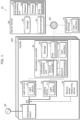
- FIG. 1 is a block diagram illustrating the functional configuration of the emission allowance management system according to the embodiment.
- Emission allowance management system 10 illustrated in FIG. 1 is a system that manages the emission amount of carbon dioxide resulting from the use of light sources 21 provided in each of a plurality of facilities 100.
- each light source 21 is a light source for illumination that has an attaching structure such as a cap and that is detachably attached to a device body of lighting device 20, and is specifically a LED (Light Emitting Diode) light bulb, a straight LED lamp, or the like.
- facility 100 is, for example, a residence (an individual house or an apartment complex), facility 100 may be an office building, a factory, a commercial establishment, an accommodation, or a public facility.
- Each of facilities 100 is provided with a plurality of lighting devices 20, illumination controller 30, distribution board 40, and electric power measuring device 50.
- Emission allowance management system 10 includes a plurality of lighting devices 20, illumination controller 30, distribution board 40, and electric power measuring device 50.
- server device 60 and information terminal 70 are located outside of facility 100.
- Emission allowance management system 10 includes server device 60 and information terminal 70. Note that information terminal 70 may be located in facility 100.
- each device provided in emission allowance management system 10 as described above will be described in detail.
- Lighting devices 20 are provided in facility 100, and illuminate the inside (indoor) of facility 100 by emitting light (for example, white light). Lighting devices 20 may be lighting devices that are provided outdoor in vicinity of facility 100, and that illuminate the outdoor by emitting light (for example, white light). More specifically, lighting device 20 includes a device body (not illustrated) and light source 21.
- Light source 21 is light source device for illumination that is detachably attached to the device body. As described above, specifically, light source 21 is a LED light bulb, a straight LED lamp, and the like. It is not essential that light source 21 is realized by a LED element, and light source 21 may be realized by other light emitting elements, such as an organic EL (Electro-Luminescence).
- organic EL Electro-Luminescence
- one light source 21 is attached to one lighting device 20
- a plurality of light sources 21 may be attached to one lighting device 20.
- Illumination controller 30 is provided in facility 100, and controls lighting devices 20 provided in the same facility 100. Specifically, although illumination controller 30 controls turning on and off of lighting devices 20, illumination controller 30 may further control dimming and color adjustment. Illumination controller 30 may be an exclusive controller for lighting devices 20, or may be an EMS (Energy Management System) controller or the like. Illumination controller 30 may be a controller fixed to a wall or a ceiling, or may be a portable controller. Illumination controller 30 includes first communicator 31, second communicator 32, information processing unit 33, storage 34, and user interface 35.
- EMS Electronicgy Management System
- First communicator 31 is a communication circuit for illumination controller 30 to communicate with server device 60 and the like via wide area communication network 80.
- first communicator 31 is, for example, a wireless communication circuit that performs wireless communication
- first communicator 31 may be a wired communication circuit that performs wired communication.
- the communication standard for communication performed by first communicator 31 is not particularly limited.
- Second communicator 32 is a communication circuit for illumination controller 30 to communicate with lighting devices 20 and the like via a local communication network.
- second communicator 32 is, for example, a wireless communication circuit that performs wireless communication
- second communicator 32 may be a wired communications circuit that performs wired communication.
- the communication standard for communication performed by second communicator 32 is not particularly limited.
- Information processing unit 33 performs information processing related to control of lighting devices 20.
- information processing unit 33 is realized by, for example, a microcomputer, information processing unit 33 may be realized by a processor.
- Information processing unit 33 includes, as a functional component, second controller 36 that transmits a control signal to lighting devices 20 via second communicator 32 based on an operation by a user that is received by user interface 35.
- the function of second controller 36 is realized by, for example, executing a computer program stored in storage 34 by a microcomputer, a processor, or the like that constitutes information processing unit 33.
- Storage 34 is a storage device that stores a computer program and the like that are executed by information processing unit 33.
- Storage 34 is realized by, for example, a semiconductor memory.
- User interface 35 receives an operation by the user, and presents information to the user.
- User interface 35 is realized by a touch panel or hardware key (push button) that receives an operation by the user, and a display panel, such as a liquid crystal panel or an organic EL panel.
- Distribution board 40 distributes alternating current power supplied from system power supply 90 to a plurality of branch circuits. Each of the plurality of branch circuits is connected to an instrument, such as lighting device 20.
- Electric power measuring device 50 measures the amount of power used (in other words, the power consumption amount) at predetermined measuring point MP.
- Electric power measuring device 50 uses, for example, a current sensor (CT: Current Transformer) attached to an electric wire corresponding to a branch circuit to which a plurality of lighting devices 20 are connected to measure the amount of power used in the branch circuit (electric wire). Additionally, electric power measuring device 50 transmits a measured value of the amount of power used to server device 60 through wide area communication network 80.
- CT Current Transformer
- a measuring function of the amount of power used similar to the measuring function of electric power measuring device 50 may be included in distribution board 40, or may be included in illumination controller 30.
- the measuring function (measuring unit) of the amount of power used is included in distribution board 40 or illumination controller 30, electric power measuring device 50 may be omitted.
- lighting device 20 has a function of measuring the amount of power used by lighting device 20 itself (light source 21) as will be described later, electric power measuring device 50 may be omitted.
- Server device 60 is a cloud server that performs information processing on management of the emission amount of carbon dioxide resulting from the use of light sources 21.
- Server device 60 is used by, for example, a business entity that performs manufacturing and sales of light sources 21.
- server device 60 includes communicator 61, information processing unit 62, and storage 63.
- Communicator 61 is a communication circuit for server device 60 to communicate with illumination controller 30, information terminal 70, and the like through wide area communication network 80.
- communicator 61 is, for example, a wired communicator that performs wired communication
- communicator 61 may be a wireless communication circuit that performs wireless communication.
- the communication standard for communication performed by communicator 61 is not particularly limited.
- Information processing unit 62 performs information processing on management of the emission amount of carbon dioxide resulting from the use of light sources 21.
- information processing unit 62 is realized by a microcomputer or a processor.
- Information processing unit 62 has, as functional components, obtainer 64, manager 65, and first controller 66.
- the functions of obtainer 64, manager 65, and first controller 66 are realized by, for example, executing a computer program stored in storage 63 by a microcomputer or a processor constituting information processing unit 62. The details of the functions of obtainer 64, manager 65, and first controller 66 will be described later.
- Storage 63 is a storage device that stores various kinds of information, the above-described computer program, and the like required for the above-described information processing.
- storage 63 is realized by, for example, a HDD (Hard Disk Drive), storage 63 may be realized by a semiconductor memory.
- emission allowance management system 10 can manage the emission amount of carbon dioxide resulting from the use of light sources 21, and emission allowance management information is stored in advance in storage 63.
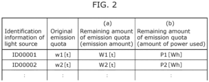
- FIG. 2 is a diagram illustrating an example of the emission allowance management information.
- the identification information of light source 21 is associated with the original emission quota of carbon dioxide allocated to that light source 21, and with the remaining amount of the emission quota of carbon dioxide allocated to that light source 21.
- the remaining amount of the emission quota is represented by the emission amount [t] of carbon dioxide ((a) of FIG. 2 ), and is also represented by the amount of power used [Wh] ((b) of FIG. 2 ). Note that the emission amount of carbon dioxide can be converted to the amount of power used by a predetermined calculation formula.
- the remaining amount of the emission quota of carbon dioxide of light source 21 in the emission allowance management information is equal to the original emission quota.
- emission allowance management system 10 when the user purchases light source 21, and uses the purchased light source 21 (causes light source 21 to emit light), the remaining amount of the emission quota is decreased, and when the remaining amount of the emission quota reaches 0, light source 21 cannot be used. Note that the user will purchase light source 21 for which the price is set so as to include the cost corresponding to the emission quota of carbon dioxide.
- the emission amount of carbon dioxide of light source 21 may be managed by using the remaining amount of the emission quota of carbon dioxide in terms of the amount of power used illustrated in the column (b) of FIG. 2
- the emission amount of carbon dioxide of light source 21 may be managed by using the remaining amount of the emission quota corresponding to the emission amount of carbon dioxide illustrated in the column (a) of FIG. 2
- the emission allowance management information may include at least one of the column (a) of FIG. 2 and the column (b) of FIG. 2 .
- Information terminal 70 is an information terminal that is used by the user for registration of information to server device 60 and the like.
- Information terminal 70 is, for example, a portable information terminal such as a smart phone or a tablet terminal.
- Information terminal 70 may be a stationary information terminal such as a personal computer.
- Information terminal 70 includes user interface 71.
- User interface 71 receives an operation by the user, and presents information to the user.
- User interface 71 is realized by a touch panel or hardware key (push button) that receives an operation by the user, and a display panel, such as a liquid crystal panel or an organic EL panel.
- a touch panel or hardware key push button
- a display panel such as a liquid crystal panel or an organic EL panel.
- emission allowance management system 10 can manage the emission amount of carbon dioxide resulting from the use of light sources 21.
- Operation Example 1 of emission allowance management system 10 as described above will be described.
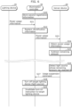
- FIG. 3 is a sequence diagram of Operation Example 1 of emission allowance management system 10.
- FIG. 4 is a diagram illustrating an example of the first registration information.
- Registration of the identification information in step S10 is performed by, for example, inputting the identification information of light source 21 and the identification information of electric power measuring device 50 to information terminal 70 by a manual operation by the user to user interface 71 of information terminal 70, and the like.
- the identification information of light source 21 is displayed on the body of light source 21, a wrapping package, an operation manual, or the like. The same applies to the identification information of electric power measuring device 50.
- Each of the identification information of light source 21 and the identification information of electric power measuring device 50 may be displayed by a two-dimensional code, such as a QR Code (registered trademark).
- a two-dimensional code such as a QR Code (registered trademark).
- information terminal 70 includes a camera
- the two-dimensional code indicating the identification information of light source 21 is displayed on the body of light source 21, the wrapping package, the operation manual, or the like
- the user can easily input the identification information of light source 21 to information terminal 70 by photographing the two-dimensional code by using information terminal 70.
- the user can easily input the identification information of light source 21 to information terminal 70 by photographing the two-dimensional code by using information terminal 70.
- FIG. 5 is a diagram illustrating an example of the second registration information. Note that the identification information of lighting device 20 is displayed on the body of lighting device 20, a wrapping package, an operation manual, or the like.
- Registration of the identification information is performed by, for example, inputting the identification information of light source 21 and the identification information of lighting device 20 to illumination controller 30 by a manual operation by the user to user interface 35 of illumination controller 30, and the like.
- electric power measuring device 50 measures the amount of power used at predetermined measuring point MP (illustrated in FIG. 1 ), and transmits power usage information, which indicates the measured amount of power used, to server device 60 (S12).
- the identification information of electric power measuring device 50 is included in the power usage information.
- the identification information of electric power measuring device 50 is an example of specification information, and is used for specifying the identification information of target light source 21 in the next step S13.
- Communicator 61 of server device 60 receives power usage information, and obtainer 64 obtains the power usage information received by communicator 61 (S13).
- Manager 65 calculates the amount of power used per light source 21, based on the obtained power usage information and the first registration information (S14).
- manager 65 extracts the identification information of electric power measuring device 50 from the power usage information obtained in step S13, and specifies, in the first registration information, the total number of items of the identification information of light source 21 (hereinafter also described as target light source 21) associated with the identification information of extracted electric power measuring device 50.
- Manager 65 can divide the amount of power used per target light source 21 by dividing the amount of power used indicated by the power usage information by the total number of items of the identification information of target light source 21. For example, when the amount of power used obtained in step S13 indicates that the total amount of the amount of power used by five light sources 21 ID00001 to ID00005 is P, manager 65 can calculate that the amount of power used of each of five light sources 21 ID00001 to ID00005 is P/5.
- manager 65 subtracts the calculated amount of power used from the remaining amount of the emission quota of carbon dioxide in the emission allowance management information (S15). For example, manager 65 subtracts P/5 from the remaining amount of the emission quota (the amount of power used) of each of five light sources 21 ID00001 to ID00005 in the emission allowance management information.
- the processing from step S12 to step S15 is repeated at predetermined time intervals.
- the predetermined time interval is, for example, one hour, but is not particularly limited.
- manager 65 After the processing from step S12 to step S15 is repeated several times, manager 65 detects light source 21 whose remaining amount of the emission quota of carbon dioxide has reached 0, based on the emission allowance management information (S16). First controller 66 uses communicator 61 to transmit, to illumination controller 30, a usage suspension command for making light source 21 whose detected remaining amount is 0 unusable (S17). The usage suspension command includes the identification information of the detected light source 21.
- First communicator 31 of illumination controller 30 receives the usage suspension command. Based on the received usage suspension command, second controller 36 determines whether or not the identification information of light source 21 that is a target of usage suspension is included in the second registration information. When second controller 36 determines that the identification information of light source 21 that is the target of usage suspension is included in the second registration information, second controller 36 turns off lighting device 20 (hereinafter also described as target lighting device 20) to which that light source 21 is attached (S18). Specifically, second controller 36 uses second communicator 32 to transmit, to target lighting device 20, a control signal for turning off target lighting device 20.
- target lighting device 20 hereinafter also described as target lighting device 20
- second controller 36 invalidates a turn-on instruction to target lighting device 20 (S19). Specifically, even if the user performs an operation to instruct turning on of target lighting device 20 on user interface 35, second controller 36 does not transmit, to target lighting device 20, a control signal for turning on target lighting device 20.
- emission allowance management system 10 although light source 21 can be used until the remaining amount of the emission quota becomes 0, when the remaining amount of the emission quota becomes 0, light source 21 cannot be used even though there is no hardware problem (no malfunction). In other words, according to emission allowance management system 10, although light source 21 can be turned on until the remaining amount of the emission quota becomes 0, when the remaining amount of the emission quota becomes 0, light source 21 cannot be turned on. According to emission allowance management system 10, a business entity that manufactures and sells light sources 21 can manage the emission amount of carbon dioxide resulting from the use of light sources 21.
- FIG. 6 is a sequence diagram of Operation Example 2 of emission allowance management system 10.
- step S20 the processing in step S20 is the same as that in step S11 of Operation Example 1, a detailed description is omitted.
- lighting device 20 measures the amount of power used of lighting device 20, and transmits, to illumination controller 30, the power usage information, which indicates the measured amount of power used (S21).
- the power usage information which indicates the measured amount of power used (S21).
- DALI registered trademark
- DALI Part 252 - Energy Reporting defines the measuring method of the amount of power used in lighting device 20 (refer to DiiA Specification, DALI Part 252 - Energy Reporting), and lighting device 20 can measure the amount of power used according to, for example, such a standard.
- the identification information of lighting device 20 is included in the power usage information.
- Second communicator 32 of illumination controller 30 receives the power usage information.
- Information processing unit 33 replaces the identification information of lighting device 20 included in the power usage information with the identification information of light source 21 based on the second registration information (S22), and transmits the identification information of light source 21 to server device 60 by using first communicator 31 (S23).
- the power usage information transmitted to server device 60 in step S23 is the information that indicates the amount of power used of light source 21, and that includes the identification information of light source 21 as the specification information. Note that, when a plurality of light sources 21 are attached to one lighting device 20, the power usage information transmitted to server device 60 in step S23 includes the identification information of a plurality of light sources 21.
- Communicator 61 of server device 60 receives the power usage information, and obtainer 64 obtains the power usage information received by communicator 61 (S24).
- Manager 65 subtracts the amount of power used indicated by the power usage information obtained in step S23 from the remaining amount of the emission quota of carbon dioxide associated with the identification information included in the power usage information obtained in step S24 in the emission allowance management information (S25). For example, when the amount of power used indicated by power usage information is P, and the identification information of ID00001 is included in the power usage information, manager 65 subtracts P/5 from the remaining amount of the emission quota (the amount of power used) of light source 21 of ID00001 in the emission allowance management information.
- step S25 when the identification information of a plurality of light sources 21 is included in the power usage information obtained in step S24 (that is, when a plurality of light sources 21 are attached to one lighting device 20), processing of calculating the amount of power used per light source is performed in step S25.
- the amount of power used indicated by the power usage information is P
- two items of identification information i.e., ID00001 and ID00002
- manager 65 subtracts P/2 from the remaining amount of the emission quota (the amount of power used) of each of two light sources 21 ID00001 and ID00002 in the emission allowance management information.
- the processing from step S21 to step S25 is repeated at predetermined time intervals.
- the predetermined time interval is, for example, one hour, but is not particularly limited.
- manager 65 After the processing from step S21 to step S25 is repeated several times, manager 65 detects light source 21 whose remaining amount of the emission quota of carbon dioxide has reached 0, based on the emission allowance management information (S26). Since the subsequent processing from step S26 to step S29 is the same as that from step S16 to step S19 of Operation Example 1, a detailed description is omitted.
- emission allowance management system 10 can manage the emission amount of carbon dioxide resulting from the use of light sources 21.
- the replacement processing of the identification information (the processing in step S22) is performed in illumination controller 30, it may be performed in server device 60.
- manager 65 of server device 60 can perform the replacement processing of the identification information.
- the identification information of lighting device 20 included in the power usage information transmitted by lighting device 20 functions as the specification information for specifying light source 21.
- lighting device 20 since the power usage information transmitted by lighting device 20 need not go through illumination controller 30, lighting device 20 may be connected to wide area communication network 80 without going through illumination controller 30, and may transmit the power usage information to server device 60.
- lighting device 20 can directly obtain the identification information of light source 21 attached to that lighting device 20, lighting device 20 can transmit the power usage information including the identification information of light source 21.
- lighting device 20 can obtain the identification information of light source 21 from the RFID tag when light source 21 is attached to lighting device 20.
- the replacement processing of the identification information becomes unnecessary in both illumination controller 30 and server device 60, and advanced registration of the second registration information also becomes unnecessary.
- the required illuminance is defined in a space in facility 100, for example, in an office, the illuminance at hand is required to be 500 lux or more, and the illuminance at feet is required to be 300 lux or more.
- the illuminance in the space illuminated by that light source 21 may become insufficient.
- emission allowance management system 10 may perform an operation of supplementing the brightness in the space.
- the arrangement information indicating the arrangement of a plurality of lighting devices 20 is stored in storage 34 of illumination controller 30.
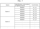
- FIG. 7 is a diagram illustrating an example of the arrangement information.
- the identification information of lighting device 20, the space where lighting device 20 is arranged, and the two-dimensional coordinates of lighting device 20 are associated with each other.
- the space here means, for example, a closed space, and when facility 100 is a residence, each of chambers, such as a living room, a bedroom, and a bathroom, corresponds to the space.
- the arrangement information is stored in storage 34 of illumination controller 30 by a manual operation to user interface 35 at the time of, for example, the construction of a plurality of lighting devices 20 (device bodies) and illumination controller 30. Since the identification information of lighting device 20 in the arrangement information can be replaced with the identification information of light source 21 based on the second registration information, it can be said that the arrangement information is information indicating the arrangement of a plurality of light sources 21.
- FIG. 8 is a flowchart of Operation Example 3 of emission allowance management system 10.
- first communicator 31 of illumination controller 30 receives a usage suspension command from server device 60 (S30), and second controller 36 causes target lighting device 20 to be turned off based on the received usage suspension command (S31). Additionally, second controller 36 invalidates a turn-on instruction to target lighting device 20 (S32).
- second controller 36 sequentially selects n (n is a natural number) lighting devices 20 from lighting devices 20 that are arranged in the same space as target lighting device 20, and that have coordinates (a distance) close to the coordinates of target lighting device 20 (S33).
- n is empirically or experimentally defined in advance by a designer or the like of emission allowance management system 10.
- lighting device 20 in the state where turning on is disabled based on the usage suspension command is excluded.
- the requirement of belonging to the same space is not essential, and more simply, n lighting devices 20 may be sequentially selected from lighting devices that have coordinates close to the coordinates of target lighting device 20.
- second controller 36 increases the brightness during turning on of selected n lighting devices 20 before target lighting device 20 becomes unusable (S34).
- second controller 36 increases the brightness of the other light sources 21 located in vicinity of target light source 21.
- second controller 36 can increase the brightness of selected n lighting devices 20 by transmitting a control signal to selected n lighting devices 20 by using second communicator 32.
- the degree to which the brightness is increased can be empirically or experimentally determined in advance by a designer or the like of emission allowance management system 10.
- emission allowance management system 10 can perform the operation of supplementing the brightness in the space.
- the emission allowance management information may include group identification information indicating a group to which each of a plurality of light sources 21 belongs.
- FIG. 9 is a diagram illustrating an example of the emission allowance management information including the group identification information.
- the group identification information is assigned to the emission allowance management information by, for example, a manual operation by the user to user interface 71 of information terminal 70. For example, the user assigns the group identification information so that light sources 21 located in the same space belong to the same group.
- first controller 66 controls light sources 21 belonging to the same group to be unusable, based on the total of the remaining amount of the emission quota of the light sources belonging to the same group.
- light source 21 of ID00001 and light source 21 of ID00002 belong to the same group.
- first controller 66 does not perform control to make light source 21 of ID00001 unusable. That is, the user can use two light sources 21 until the total P1+P2 of the remaining amounts of the emission quotas of two light sources 21 reaches 0.
- group identification information is assigned such that light sources 21 located in the same space belong to the same group, it becomes less likely that only a part of light sources 21 located in the same space become unusable.
- manager 65 determines whether to stop light source 21 by using one hour as the minimum unit, as a result of the determination, a situation may occur in which, in the next one hour, only one light source 21 can be used, but two light sources 21 cannot be used.
- light sources 21 belonging to the same group may be assigned priorities.
- the priorities are assigned to the emission allowance management information by, for example, a manual operation by the user to user interface 71 of information terminal 70.
- first controller 66 controls light sources 21 belonging to the same group to be unusable in an order based on the priorities. Specifically, first controller 66 sequentially controls light sources 21 belonging to the same group to be unusable, starting from light source 21 with the lowest priority.
- emission allowance management system 10 can also manage the remaining amount of the emission quota on a group basis.
- Emission allowance management system 10 may perform, for example, an operation of transferring the remaining amount of the emission quota of existing light source 21 to new light source 21.
- an operation of transferring the remaining amount of the emission quota of existing light source 21 to new light source 21 Asinafter, such a transfer operation (Operation Example 4) of the remaining amount of emission quota will be described.
- FIG. 10 is a sequence diagram of Operation Example 4 of emission allowance management system 10.
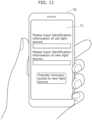
- FIG. 11 is a diagram illustrating an example of the display screen for receiving a transfer operation of the emission quota.
- the transfer operation includes an input operation of the identification information of old light source 21 (an example of first light source), an input operation of the identification information of new light source 21 (an example of second light source), and the like.
- information terminal 70 transmits a transfer request to server device 60 (S42).
- the transfer request includes the identification information of old light source 21 and the identification information of new light source 21.
- Communicator 61 of server device 60 receives the transfer request.
- Obtainer 64 obtains the transfer request (S43).
- Manager 65 transfers the remaining amount of the emission quota based on the obtained transfer request (S44). For example, when the remaining amount of new light source 21 is P1, and the remaining amount of old light source 21 is P2, manager 65 subtracts the remaining amount associated with the identification information of new light source 21 in the emission allowance management information from P1 to 0, and adds P1 to the remaining amount P2 associated with the identification information of new light source 21 in the emission allowance management information. Accordingly, the remaining amount of the emission quota of old light source 21 is transferred to new light source 21.
- emission allowance management system 10 can transfer the remaining amount of the emission quota from new light source 21 to old light source 21.
- the user may acquire a compensation from a business entity by returning the remaining amount of the emission quota of old light source 21 that is no longer used to the business entity that manufactures and sells light source 21. That is, the user may sell the remaining amount of the emission quota to a business entity.
- the user may acquire the money corresponding to the remaining amount of the emission quota from a business entity, or when purchasing new light source 21, the amount of money corresponding to the remaining amount of the emission quota of old light source 21 may be discounted from the price of new light source 21.
- the returning of the remaining amount of the emission quota of old light source 21 is realized by, for example, causing information terminal 70 to execute the browser or the predetermined application program, the returning may be realized by returning (recycling) actual old light source 21 to a business entity.
- the business entity Since a business entity that manufactures and sells light source 21 performs business activities within the range of the emission quota allocated to the business entity, the business entity can expand the business activities by buying the emission quotas from users.
- the emission allowance management information described in the above-described embodiment may be visualized in a display device (not illustrated) connected to server device 60.
- Information processing unit 62 can visualize the emission allowance management information by outputting image information for displaying the emission allowance management information on the display device.
- information processing unit 62 can calculate how much carbon dioxide has been emitted by (a large number of) sold light sources 21 by aggregating the original emission quota and the remaining amount of the emission quota based on the emission allowance management information.
- information processing unit 62 can visualize how much carbon dioxide has been emitted by (a large number of) sold light sources 21 by outputting the image information including the calculation result to the display device.
- information processing unit 62 can also generate the above-described calculation result as a report (electronic file). Such a report is useful when a business entity that performs manufacturing and sales of light source 21 reports the status of the emission amount of carbon dioxide to a country and the like.
- the remaining amount of the emission quota represented by the amount of power used (column (b) of FIG. 2 ) in the emission allowance management information in FIG. 2 is provided in advance. That is, the emission amount of carbon dioxide corresponding to the emission quota has been converted in advance to the amount of power used.
- this calculation formula is different depending on the area to which facility 100 belongs. This is because the relationship between the amount of power used and the emission amount of carbon dioxide is different for each area, since an electric power company that supplies electric power is different for each area, and the breakdown of the employed electric power generation systems (thermal power generation or nuclear power generation) is different depending on the electric power company.
- manager 65 of server device 60 may convert the emission amount of carbon dioxide to the amount of power used in consideration of the area to which facility 100 belongs. For example, in Operation Example 1, when the first registration information is stored in storage 63, area information indicating the area to which facility 100 belongs is transmitted from information terminal 70 to server device 60 based on an operation by the user. Alternatively, the area information is set to electric power measuring device 50 at the time of installation of electric power measuring device 50 to facility 100, and electric power measuring device 50 transmits the area information in addition to the power usage information to server device 60, when transmitting the power usage information for the first time.
- Obtainer 64 obtains the area information together with the power usage information, and manager 65 selects a calculation formula according to the obtained area information, and converts the emission amount of carbon dioxide to the amount of power used by using the selected calculation formula.
- emission allowance management system 10 can more correctly manage the emission amount of carbon dioxide in consideration of the area to which facility 100 belongs.
- the area information is set to illumination controller 30, and first communicator 31 of illumination controller 30 transmits, to server device 60, the area information in addition to the power usage information when transmitting the power usage information for the first time.
- Obtainer 64 obtains the area information together with the power usage information, and manager 65 selects the calculation formula according to the obtained area information, and converts the emission amount of carbon dioxide to the amount of power used by using the selected calculation formula.
- emission allowance management system 10 can more correctly manage the emission amount of carbon dioxide in consideration of the area to which facility 100 belongs.
- manager 65 manages the emission amount of carbon dioxide by subtracting the amount of power used indicated by the power usage information obtained by obtainer 64 from the remaining amount of the emission quota represented by the amount of power used (column (b) of FIG. 2 ).
- manager 65 may convert the amount of power used indicated by the power usage information to the emission amount of carbon dioxide, and subtracts the emission amount of carbon dioxide from the remaining amount of the emission quota represented by the emission amount (column (a) of FIG. 2 ).
- the predetermined calculation formula is used when converting the amount of power used to the emission amount of carbon dioxide, this calculation formula is different depending on the area to which facility 100 belongs, for the reason described in Modification 2. Therefore, also when converting the amount of power used to the emission amount of carbon dioxide, similar to Modification 2, obtainer 64 may obtain the area information indicating the area to which facility 100 belongs, together with the power usage information, and manager 65 may select the calculation formula according to the obtained area information.
- emission allowance management system 10 includes: storage 63 that stores emission allowance management information indicating, for each of a plurality of light sources 21 for illumination, a relationship between (i) identification information of the light source 21 and (ii) a remaining amount of a carbon dioxide emission quota allocated to the light source 21; obtainer 64 that obtains power usage information, the power usage information including an amount of power used by target light source 21 included in the plurality of light sources 21, and including specification information for specifying identification information of target light source 21; and manager 65 that reduces the remaining amount associated with the identification information of target light source 21 in the emission allowance management information, based on the power usage information obtained by obtainer 64.
- the carbon dioxide is an example of greenhouse gas.
- Emission allowance management system 10 as described above can manage the emission amount of carbon dioxide resulting from the use of light sources 21 for illumination.
- obtainer 64 further obtains a transfer request for transferring a remaining amount of a carbon dioxide emission quota between first light source and a second light source which are included in the plurality of light sources 21, and that manager 65 adds a remaining amount associated with identification information of the first light source in the emission allowance management information to a remaining amount associated with identification information of the second light source in the emission allowance management information, based on the transfer request obtained.
- Emission allowance management system 10 as described above can transfer the remaining amount of the emission quota.
- emission allowance management system 10 further includes first controller 66 that makes target light source 21 unusable, when the remaining amount associated with the identification information of target light source 21 in the emission allowance management information is used up.
- Emission allowance management system 10 as described above can suppress an increase in the emission amount of carbon dioxide by controlling light source 21 whose remaining amount of the emission quota is used up to be unusable.
- emission allowance management system 10 further includes second controller 36 that causes light source 21 in vicinity of target light source 21 among the plurality of light sources 21 to increase a brightness, based on arrangement information indicating an arrangement of the plurality of light sources 21, when target light source 21 is made unusable.
- Emission allowance management system 10 as described above can supplement the illuminance that is decreased by controlling target light source 21 to be unusable, by causing the other light sources 21 to brightly emit light.
- the emission allowance management information further includes group identification information items indicating groups to which the plurality of light sources 21 belong, and that first controller 66 makes one or more light sources 21 belonging to a same group unusable among the plurality of light sources 21, based on a total of remaining amounts of carbon dioxide emission quotas allocated to the one or more light sources 21.
- Emission allowance management system 10 as described above can manage the remaining amount of the emission quota on a group basis.
- one or more light sources 21 belonging to the same group are assigned priorities, and that first controller 66 makes the one or more light sources 21 unusable in an order based on the priorities, when the total becomes close to zero.
- Emission allowance management system 10 as described above can control light sources 21 belonging to the same group to be unusable, based on the predetermined priorities.
- an emission allowance management method performed by a computer configured to access a storage device (storage 63) that stores emission allowance management information, the emission allowance management information indicating, for each of a plurality of light sources 21 for illumination, a relationship between (i) identification information of the light source 21 and (ii) a remaining amount of a carbon dioxide emission quota allocated to the light source 21, the emission allowance management method comprising: obtaining power usage information, the power usage information including an amount of power used by target light source 21 included in the plurality of light sources 21, and including specification information for specifying identification information of target light source 21; and reducing the remaining amount associated with the identification information of target light source 21 in the emission allowance management information, based on the power usage information obtained in the obtaining.
- the emission allowance management method as described above can manage the emission amount of carbon dioxide resulting from the use of light sources 21 for illumination.
- the emission allowance management system may manage the emission amount (emission quota) allocated to the electric instruments other than the light sources.
- the emission allowance management system is realized by a plurality of devices in the above-described embodiment, the emission allowance management system may be realized as a single device.
- the emission allowance management system may be realized as a single device corresponding to a server device.
- the components included in the emission allowance management system may be distributed to a plurality of devices in any manner. For example, a part or all of the processing that has been described to be performed by one of the illumination controller and the server device in the above-described embodiment may be performed by the other of the illumination controller and the server device.
- the communication method between the devices in the above-described embodiment is not particularly limited.
- the electric power measuring device may transmit the measured value to the illumination controller through a local communication network.
- the measured value of the amount of power used is transmitted to the server device through the wide area communication network by the illumination controller.
- a relay device for example, a wireless router or the like, which is not illustrated, may intervene in the communication between the devices.
- the process performed by a certain processing unit may be performed by another processing unit, that an order of a plurality of processes is changed, or that a plurality of processes are performed in parallel.
- Each constituent element included in the above embodiments may be realized by executing a software program suitable for the constituent element.
- Each of the constituent elements may be realized by means of a program executing unit, such as a Central Processing Unit (CPU) or a processor, reading and executing the software program recorded on a recording medium such as a hard disk or semiconductor memory.
- a program executing unit such as a Central Processing Unit (CPU) or a processor, reading and executing the software program recorded on a recording medium such as a hard disk or semiconductor memory.
- the constituent elements may be implemented to hardware.
- the constituent elements may be implemented to circuits (or integrated circuits). These circuits may form a single circuit, or serve as separate circuits.
- Each circuit may be may be a general-purpose circuit or a dedicated circuit.
- general or specific aspects of the present invention may be implemented to a system, a device, a method, an integrated circuit, or a computer program.
- the general or specific aspects of the present invention may be implemented to a non-transitory computer-readable recording medium such as an optical disk, a Hard Disk Drive (HDD), or a semiconductor memory, on which the computer program is recorded.
- a non-transitory computer-readable recording medium such as an optical disk, a Hard Disk Drive (HDD), or a semiconductor memory, on which the computer program is recorded.
- the present invention may be implemented to an illumination controller or a server device.
- the present invention may be implemented to an emission allowance management method executed by a computer such as an emission allowance management system.
- the present invention may be implemented to a program (in other words, computer program product) for causing a computer to execute the emission allowance management method.
- the present invention may be a non-transitory computer-readable recording medium on which such a program is recorded.
- the present invention may include embodiments obtained by making various modifications on the above embodiment which those skilled in the art will arrive at, or embodiments obtained by selectively combining the constituent elements and functions disclosed in the above embodiment, without materially departing from the scope of the present invention.
Landscapes
- Business, Economics & Management (AREA)
- Tourism & Hospitality (AREA)
- Health & Medical Sciences (AREA)
- Engineering & Computer Science (AREA)
- Economics (AREA)
- Physics & Mathematics (AREA)
- General Health & Medical Sciences (AREA)
- Human Resources & Organizations (AREA)
- Marketing (AREA)
- Primary Health Care (AREA)
- Strategic Management (AREA)
- General Business, Economics & Management (AREA)
- General Physics & Mathematics (AREA)
- Theoretical Computer Science (AREA)
- Water Supply & Treatment (AREA)
- Public Health (AREA)
- Management, Administration, Business Operations System, And Electronic Commerce (AREA)
Applications Claiming Priority (2)
| Application Number | Priority Date | Filing Date | Title |
|---|---|---|---|
| JP2021186561 | 2021-11-16 | ||
| PCT/JP2022/040386 WO2023090128A1 (ja) | 2021-11-16 | 2022-10-28 | 排出権管理システム、及び、排出権管理方法 |
Publications (2)
| Publication Number | Publication Date |
|---|---|
| EP4435705A1 true EP4435705A1 (de) | 2024-09-25 |
| EP4435705A4 EP4435705A4 (de) | 2025-03-05 |
Family
ID=86396773
Family Applications (1)
| Application Number | Title | Priority Date | Filing Date |
|---|---|---|---|
| EP22895411.1A Pending EP4435705A4 (de) | 2021-11-16 | 2022-10-28 | Emissionstoleranzverwaltungssystem und emissionstoleranzverwaltungsverfahren |
Country Status (4)
| Country | Link |
|---|---|
| EP (1) | EP4435705A4 (de) |
| JP (2) | JP7672082B2 (de) |
| TW (1) | TWI827353B (de) |
| WO (1) | WO2023090128A1 (de) |
Families Citing this family (1)
| Publication number | Priority date | Publication date | Assignee | Title |
|---|---|---|---|---|
| CN116862080B (zh) * | 2023-09-05 | 2024-02-09 | 国网山东省电力公司营销服务中心(计量中心) | 一种基于双视角对比学习的碳排放预测方法及系统 |
Family Cites Families (16)
| Publication number | Priority date | Publication date | Assignee | Title |
|---|---|---|---|---|
| EP1854064A4 (de) * | 2005-01-18 | 2009-03-25 | Mc Energy Inc | Verfahren und system zum verfolgen und budgetieren der energiebenutzung |
| JP4846357B2 (ja) * | 2005-12-07 | 2011-12-28 | 株式会社リコー | 電力監視ネットワークシステム |
| US20120233045A1 (en) * | 2007-05-03 | 2012-09-13 | Orion Energy Systems, Inc. | Lighting systems and methods for displacing energy consumption |
| US7715951B2 (en) * | 2007-08-28 | 2010-05-11 | Consert, Inc. | System and method for managing consumption of power supplied by an electric utility |
| WO2010067716A1 (ja) * | 2008-12-11 | 2010-06-17 | 大学共同利用機関法人情報・システム研究機構 | 排出量取引システム及び排出量取引方法 |
| CN102035201A (zh) * | 2009-09-29 | 2011-04-27 | 金宝电子工业股份有限公司 | 电力规划系统与电力规划方法 |
| TWI485949B (zh) * | 2011-01-28 | 2015-05-21 | Powertech Ind Co Ltd | 碳排放追蹤器、碳排放追蹤系統及碳排放追蹤方法 |
| TW201335880A (zh) * | 2012-02-20 | 2013-09-01 | 台灣松下電器股份有限公司 | 電器二氧化碳排放量監控系統 |
| KR20150035806A (ko) * | 2012-06-12 | 2015-04-07 | 센시티 시스템즈 아이엔씨. | 조명 인프라 및 수익 모델 |
| JP5852941B2 (ja) | 2012-08-24 | 2016-02-03 | 日立アプライアンス株式会社 | 省エネルギー行動継続支援システム |
| TWI619087B (zh) * | 2012-11-22 | 2018-03-21 | 國立高雄應用科技大學 | 具二氧化碳排放換算裝置之智慧型電錶系統 |
| TW201626316A (zh) * | 2016-03-07 | 2016-07-16 | 陳盈熹 | 運動能量發電用以減少二氧化碳的系統 |
| CN106993044B (zh) * | 2017-04-10 | 2023-11-07 | 生迪智慧科技有限公司 | 终端、基于灯的碳补偿处理系统和方法 |
| WO2020202587A1 (ja) * | 2019-04-03 | 2020-10-08 | 株式会社ウエストホールディングス | 排出権管理システム |
| TWI720652B (zh) * | 2019-10-15 | 2021-03-01 | 潤弘精密工程事業股份有限公司 | 建築能耗資訊處理方法及系統 |
| CN111476487A (zh) * | 2020-04-08 | 2020-07-31 | 厦门中智信系统集成有限公司 | 一种基于区块链的自适应能源管理方法和装置以及设备 |
-
2022
- 2022-10-28 JP JP2023561504A patent/JP7672082B2/ja active Active
- 2022-10-28 EP EP22895411.1A patent/EP4435705A4/de active Pending
- 2022-10-28 WO PCT/JP2022/040386 patent/WO2023090128A1/ja not_active Ceased
- 2022-11-09 TW TW111142689A patent/TWI827353B/zh active
-
2025
- 2025-04-10 JP JP2025065239A patent/JP2025100699A/ja active Pending
Also Published As
| Publication number | Publication date |
|---|---|
| WO2023090128A1 (ja) | 2023-05-25 |
| EP4435705A4 (de) | 2025-03-05 |
| JP2025100699A (ja) | 2025-07-03 |
| JPWO2023090128A1 (de) | 2023-05-25 |
| TWI827353B (zh) | 2023-12-21 |
| JP7672082B2 (ja) | 2025-05-07 |
| TW202324278A (zh) | 2023-06-16 |
Similar Documents
| Publication | Publication Date | Title |
|---|---|---|
| US10264652B2 (en) | Methods, systems, and apparatus for intelligent lighting | |
| JP6195750B2 (ja) | リモート調光制御照明システム | |
| US10349496B2 (en) | Lighting control system and lighting control device used therefor | |
| EP2503854A1 (de) | Beleuchtungssystem und Verfahren zu seiner Steuerung | |
| JP5861100B2 (ja) | 省エネルギー化提案システム、省エネルギー化提案方法 | |
| CN109479356A (zh) | 通用智能照明网关 | |
| JP2005032235A (ja) | エネルギー管理システム、エネルギー管理方法及び省エネルギー推奨機器情報提供装置 | |
| US8948886B2 (en) | LED lighting system and controlling method using the same | |
| JP5491215B2 (ja) | 省エネルギ診断システム | |
| EP4435705A1 (de) | Emissionstoleranzverwaltungssystem und emissionstoleranzverwaltungsverfahren | |
| US20200084855A1 (en) | Customized Photometric Data For Lighting System Designs | |
| US20150351196A1 (en) | Illumination apparatus management system and information communication terminal | |
| JP6123139B2 (ja) | 省エネルギー化提案システム、省エネルギー化サーバ、省エネルギー化提案方法 | |
| US20160088696A1 (en) | System for controlling control target units, method of controlling control target units, and recording medium | |
| CN103270770A (zh) | 设备管理系统和设备管理系统中使用的移动终端 | |
| JP6929408B2 (ja) | 利用状況のモデル化を用いた照明システム | |
| JP6757908B2 (ja) | 設定方法、設定システム及び設定プログラム | |
| Krishnan et al. | Flexible indoor environmental quality monitoring for interoperable subsystems in buildings | |
| JP5914866B2 (ja) | 省エネルギ診断システム、省エネルギ診断方法 | |
| US10383196B1 (en) | Systems and methods for controlling lighting conditions in a manufacturing environment | |
| JP2023042838A (ja) | 管理システム | |
| JP2016218681A (ja) | インセンティブ予測量提示装置 | |
| JP7445929B2 (ja) | 情報配信システム、情報配信方法およびプログラム | |
| US20240394739A1 (en) | Receiving and analyzing consumer behavior data using visible light communication | |
| JP2024163776A (ja) | 情報出力システム、及び、情報出力方法 |
Legal Events
| Date | Code | Title | Description |
|---|---|---|---|
| STAA | Information on the status of an ep patent application or granted ep patent |
Free format text: STATUS: THE INTERNATIONAL PUBLICATION HAS BEEN MADE |
|
| PUAI | Public reference made under article 153(3) epc to a published international application that has entered the european phase |
Free format text: ORIGINAL CODE: 0009012 |
|
| STAA | Information on the status of an ep patent application or granted ep patent |
Free format text: STATUS: REQUEST FOR EXAMINATION WAS MADE |
|
| 17P | Request for examination filed |
Effective date: 20240513 |
|
| AK | Designated contracting states |
Kind code of ref document: A1 Designated state(s): AL AT BE BG CH CY CZ DE DK EE ES FI FR GB GR HR HU IE IS IT LI LT LU LV MC ME MK MT NL NO PL PT RO RS SE SI SK SM TR |
|
| DAV | Request for validation of the european patent (deleted) | ||
| DAX | Request for extension of the european patent (deleted) | ||
| A4 | Supplementary search report drawn up and despatched |
Effective date: 20250130 |
|
| RIC1 | Information provided on ipc code assigned before grant |
Ipc: G01D 4/00 20060101ALI20250124BHEP Ipc: G06Q 50/06 20240101ALI20250124BHEP Ipc: G06Q 50/10 20120101AFI20250124BHEP |