EP4435409A1 - Messvorrichtung und messverfahren - Google Patents
Messvorrichtung und messverfahren Download PDFInfo
- Publication number
- EP4435409A1 EP4435409A1 EP22895230.5A EP22895230A EP4435409A1 EP 4435409 A1 EP4435409 A1 EP 4435409A1 EP 22895230 A EP22895230 A EP 22895230A EP 4435409 A1 EP4435409 A1 EP 4435409A1
- Authority
- EP
- European Patent Office
- Prior art keywords
- cmr
- signal
- sensor signal
- reference light
- fluorescence
- Prior art date
- Legal status (The legal status is an assumption and is not a legal conclusion. Google has not performed a legal analysis and makes no representation as to the accuracy of the status listed.)
- Pending
Links
Images


Classifications
-
- G—PHYSICS
- G01—MEASURING; TESTING
- G01N—INVESTIGATING OR ANALYSING MATERIALS BY DETERMINING THEIR CHEMICAL OR PHYSICAL PROPERTIES
- G01N21/00—Investigating or analysing materials by the use of optical means, i.e. using sub-millimetre waves, infrared, visible or ultraviolet light
- G01N21/62—Systems in which the material investigated is excited whereby it emits light or causes a change in wavelength of the incident light
- G01N21/63—Systems in which the material investigated is excited whereby it emits light or causes a change in wavelength of the incident light optically excited
- G01N21/64—Fluorescence; Phosphorescence
-
- G—PHYSICS
- G01—MEASURING; TESTING
- G01N—INVESTIGATING OR ANALYSING MATERIALS BY DETERMINING THEIR CHEMICAL OR PHYSICAL PROPERTIES
- G01N24/00—Investigating or analyzing materials by the use of nuclear magnetic resonance, electron paramagnetic resonance or other spin effects
- G01N24/006—Investigating or analyzing materials by the use of nuclear magnetic resonance, electron paramagnetic resonance or other spin effects using optical pumping
-
- G—PHYSICS
- G01—MEASURING; TESTING
- G01N—INVESTIGATING OR ANALYSING MATERIALS BY DETERMINING THEIR CHEMICAL OR PHYSICAL PROPERTIES
- G01N21/00—Investigating or analysing materials by the use of optical means, i.e. using sub-millimetre waves, infrared, visible or ultraviolet light
- G01N21/62—Systems in which the material investigated is excited whereby it emits light or causes a change in wavelength of the incident light
- G01N21/63—Systems in which the material investigated is excited whereby it emits light or causes a change in wavelength of the incident light optically excited
- G01N21/64—Fluorescence; Phosphorescence
- G01N21/6402—Atomic fluorescence; Laser induced fluorescence
-
- G—PHYSICS
- G01—MEASURING; TESTING
- G01R—MEASURING ELECTRIC VARIABLES; MEASURING MAGNETIC VARIABLES
- G01R33/00—Arrangements or instruments for measuring magnetic variables
- G01R33/20—Arrangements or instruments for measuring magnetic variables involving magnetic resonance
- G01R33/24—Arrangements or instruments for measuring magnetic variables involving magnetic resonance for measuring direction or magnitude of magnetic fields or magnetic flux
- G01R33/26—Arrangements or instruments for measuring magnetic variables involving magnetic resonance for measuring direction or magnitude of magnetic fields or magnetic flux using optical pumping
-
- G—PHYSICS
- G01—MEASURING; TESTING
- G01R—MEASURING ELECTRIC VARIABLES; MEASURING MAGNETIC VARIABLES
- G01R33/00—Arrangements or instruments for measuring magnetic variables
- G01R33/20—Arrangements or instruments for measuring magnetic variables involving magnetic resonance
- G01R33/28—Details of apparatus provided for in groups G01R33/44 - G01R33/64
- G01R33/32—Excitation or detection systems, e.g. using radio frequency signals
- G01R33/323—Detection of MR without the use of RF or microwaves, e.g. force-detected MR, thermally detected MR, MR detection via electrical conductivity, optically detected MR
Definitions
- the present invention relates to a measurement device and a measurement method.
- a magnetic field measurement device performs magnetic measurement using optically detected magnetic resonance (ODMR) in which electron spin resonance of a sensing member such as a diamond structure having nitrogen and lattice defects (NV center: Nitrogen Vacancy Center) is utilized.
- ODMR optically detected magnetic resonance
- a static magnetic field is applied to a magnetic resonance member such as diamond that has the NV center in separation from a measured magnetic field, and at the same time, laser light (excitation light for initialization and measurement) and a microwave are applied in a predetermined sequence.
- An amount of light of fluorescence emitted from the magnetic resonance member is detected and a magnetic flux density of the measured magnetic field is derived based on the amount of light.
- a spin echo pulse sequence (a) the excitation light is irradiated to the NV center, (b) the first n/2 pulse of the microwave is applied to the NV center at a phase of 0 degrees of a measured magnetic field, (c) a ⁇ pulse of the microwave is applied to the NV center at a phase of 180 degrees of the measured magnetic field, (d) the second n/2 pulse of the microwaves is applied to the NV center at a phase of 360 degrees of the measured magnetic field, (e) the excitation light is irradiated to the NV center and the light emission amount from the NV center is measured by irradiating the excitation light to the NV center, and (f) the magnetic flux density is derived based on the measured light emission amount.
- a certain sensor device measures a magnetic field by nuclear magnetic resonance using a diamond sensor including the NV center as mentioned above (for instance, refer to Patent Document 1).
- Patent Document 1 Japanese Patent Publication Number 2019-138772 .
- An object of the present invention is to obtain a measurement device and a measurement method that suppress a noise component caused by irradiation light and improve measurement accuracy.
- a measurement device has a magnetic resonance member, a high frequency magnetic field generator, a light emitting device, a fluorescence light receiving device, a CMR arithmetic part, a first analog/digital converter, a second analog/digital converter, and an arithmetic processing device.
- a magnetic resonance member an electron spin quantum state changes in response to a field to be measured (a measured field) and an electron spin quantum operation is performed by using a microwave.
- the high frequency magnetic field generator performs the electron spin quantum operation of the magnetic resonance member by using the microwave.
- the light emitting device emits excitation light irradiate to the magnetic resonance member.
- the fluorescence light receiving device receives fluorescence emitted by the magnetic resonance member in response to the excitation light and generates a fluorescence sensor signal corresponding to an intensity of the fluorescence.
- the CMR arithmetic part performs common mode rejection with respect to the fluorescence sensor signal based on a reference light sensor signal and generates a CMR signal based on the common mode rejection.
- the reference light sensor signal is generated by receiving reference light.
- the reference light is obtained by branching the excitation light.
- the first analog/digital converter digitizes the CMR signal.
- the second analog/digital converter digitizes the reference light sensor signal that is generated by receiving the reference light.
- the reference light is obtained by branching the excitation light.
- the arithmetic processing device generates a detection signal based on the digitized CMR signal and the digitized reference light sensor signal and derives a measurement value of the field to be measured based on the detection signal. Further, the CMR arithmetic part performs the above-mentioned common mode rejection in consideration of nonlinearity of a level of the fluorescence sensor signal corresponding to an amount of the above-mentioned excitation light. Further, the arithmetic processing device performs digital filter processing for noise removal with respect to the digitized CMR signal or the detection signal.
- a measurement method includes (a) performing an electron spin quantum operation with respect to a magnetic resonance member by using a microwave according to a predetermined measurement sequence and emitting excitation light irradiate to the magnetic resonance member, an electron spin quantum state being changed in response to a field to be measured (a measured field) and the electron spin quantum operation being performed by using the microwave in the magnetic resonance member, (b) receiving fluorescence emitted by the magnetic resonance member in response to the excitation light and generating a fluorescence sensor signal corresponding to an intensity of the fluorescence, (c) performing common mode rejection with respect to the fluorescence sensor signal based on a reference light sensor signal in consideration of nonlinearity of a level of the fluorescence sensor signal corresponding to an amount of the excitation light and generating a CMR signal based on the common mode rejection, the reference light sensor signal being generated by receiving reference light, the reference light being obtained by branching the excitation light, (d) digitizing the CMR signal, (e) digitizing a reference light sensor signal that is
- the present invention it is possible to obtain a measurement device and a measurement method that suppress a noise component caused by irradiation light and improve measurement accuracy.
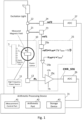
- Fig. 1 is a block diagram that shows a configuration of a measurement device according to an embodiment of the present invention.
- the measurement device shown in Fig. 1 has a sensor part 10, a high frequency power source 11, a light emitting device 12, and a light receiving device 13.
- the sensor part 10 detects a field to be measured (a measured field, for instance, a magnetic field such as an intensity and a direction of the magnetic field) at a predetermined position (for instance, on or above a surface of an object to be inspected).
- a field to be measured may be an alternating current field with a single frequency, an alternating current field with a predetermined cycle having a plurality of frequency components, or a direct current field.
- the sensor part 10 has a magnetic resonance member 1, a high frequency magnetic field generator 2, and a magnet 3, and detects the measured field by using the ODMR.
- the magnetic resonance member 1 has a crystal structure. An electron spin quantum state of the magnetic resonance member 1 changes in correspond with the measured field (here, a magnetic field), and at the same time, the magnetic resonance member 1 is a member in which it is capable of an electron spin quantum operation by a microwave at a frequency that corresponds to an arrangement direction of defects and impurities in a crystal lattice (based on Rabi oscillation). That is, the magnetic resonance member 1 is placed at the position where a magnetic field is measured.
- the magnetic resonance member 1 is an optically detected magnetic resonance member having a plurality (that is, an ensemble) of specific color centers.
- This specific color center has an energy level capable of Zeeman splitting, and at the same time, can take a plurality of directions in which shift widths of the energy level at the time of Zeeman splitting are different from each other.
- the magnetic resonance member 1 is a member such as a diamond that includes a plurality of NV (Nitrogen Vacancy) centers as a specific color center of a single category (or type).
- NV Nonrogen Vacancy
- the color center included in the magnetic resonance member 1 may be a color center other than the NV center.
- the high frequency magnetic field generator 2 applies a microwave to the magnetic resonance member 1 so as to perform an electron spin quantum operation of the magnetic resonance member 1.
- the high frequency magnetic field generator 2 is a plate-shaped coil and has a substantially circular coil part that emits the microwave and terminal parts that extend from both ends of the coil part and are fixed to the substrate.
- the high frequency power source 11 generates a current of the microwave and is conductively connected to the high frequency magnetic field generator 2.
- the coil part conducts two currents that are mutually in parallel at a predetermined interval so as to sandwich the magnetic resonance member 1 at both end surface parts of the coil part and emit the above-mentioned microwave.
- the coil part is a plate-shaped coil, however, because the current of the microwave flows through the end surface part of the coil part due to a skin effect, two currents are formed. As a result, the microwave with a spatially uniform intensity is applied to the magnetic resonance member 1.
- the color center is formed by a defect (vacancy) (V) and nitrogen (N) as an impurity in the diamond crystal
- N defect
- N defect
- N defect
- N defect
- N defect
- N defect
- N defect
- N defect
- N defect
- N defect
- N defect
- N defect
- N defect
- N defect
- N defect
- N defect
- N defect
- N defect
- N defect
- N defect
- N the arrangement directions of a pair of the vacancy and the nitrogen
- the magnet 3 applies a static magnetic field (a DC magnetic field) to the magnetic resonance member 1 so that the energy levels of a plurality of specific color centers (here, a plurality of NV centers) in the magnetic resonance member 1 undergo Zeeman splitting.
- a static magnetic field a DC magnetic field
- the magnet 3 is a ring-type permanent magnet, such as a ferrite magnet, an alnico magnet, or a samarium cobalt magnet.
- an application direction of the above-mentioned static magnetic field is the same as an application direction of the above-mentioned measured magnetic field, by applying the above-mentioned static magnetic field, the change of the fluorescence intensity at the above-mentioned dip frequency is enhanced and the sensitivity is increased.
- the magnetic resonance member 1 is provided with the plurality of color centers (here, the NV centers) in which it is capable of the electron spin quantum operation by the above-mentioned microwaves.
- the magnet 3 applies the substantially uniform static magnetic field to a predetermined region (an irradiation region of the excitation light) of the magnetic resonance member 1.
- the static magnetic field is applied as a difference or a ratio between the maximum value and the minimum value of the intensities of the static magnetic field in the predetermined region is equal to or less than a predetermined value.
- an optical system from the light emitting device 12 to the magnetic resonance member 1 is provided. Further, in order to detect fluorescence from the magnetic resonance member 1, an optical system from the magnetic resonance member 1 to the light receiving device 13 is provided.
- the light emitting device 12 has, such as a laser diode, as a light source and the light source emits laser light having a predetermined wavelength as excitation light to irradiate the magnetic resonance member 1.
- the light receiving device 13 has, such as a photodiode or a phototransistor, as a light receiving element, receives the fluorescence emitted by the magnetic resonance member 1 in correspond with the excitation light, and generates a fluorescence sensor signal PL corresponding to the intensity of the fluorescence. This fluorescence is concentrated toward the light receiving device 13 by an optical system such as a compound parabolic concentrator (CPC).
- CPC compound parabolic concentrator
- Fig. 2 is a diagram that explains the nonlinearity of the level of the fluorescence sensor signal with respect to an amount of the excitation light. For instance, as shown in Fig. 2 , the inclination of the level of the fluorescence sensor signal PL is large as the fluorescence intensity is small.
- the function f and the constant ⁇ are derived in advance by, such as experiments, on a sensor of the light receiving device 13. Further, this function f may have another function form such as an exponential function.
- a level ref of a reference light sensor signal of reference light being branched from the excitation light is proportional to the intensity I of the excitation light, it is expressed as the following equation. Further, because the intensity of the reference light is relatively high, the level of the reference light sensor signal PL is linear (proportional) with reference to the intensity of the reference light.
- ⁇ is a constant. Note that ref1 and ref2 will be explained later.
- PL is expressed by the above equation by ignoring a cubic term and subsequent terms because of I noise ⁇ I laser after Taylor expansion is performed with respect to PL.
- a CMR signal CMR_SIG(t) is derived from the PL and the ref by subjecting the above PL and the ref to Taylor expansion (Maclaurin expansion) using I noise and approximating them while ignoring the cubic term and the subsequent terms.
- PL (I laser + I noise ) indicates that the PL is a function of (I laser + I noise ), and PL (I laser ) is the PL when I noise is set to 0.
- ref (I laser + I noise ) indicates that the ref is a function of (I laser + I noise ), and ref (I laser ) is the ref when I noise is set to 0.
- PL (I laser + I noise) PL (I laser) + PL' (I laser) I noise + ...
- ref (I laser + I noise) ref (I laser) + ref' (I laser) I noise + ...
- CMR_SIG(t) PL - (PL' (I laser) / ref' (I laser) )ref
- the measurement device shown in Fig. 1 further has light separation parts 21 and 22 as optical elements on an optical path of the excitation light from the light emitting device 12 to the magnetic resonance member 1.
- the light separation parts 21 and 22 respectively branch a part of the excitation light from the excitation light and emit the part of the excitation light in a different direction as the reference light.
- the light separation parts 21 and 22 are deflection independent beam splitters.
- the measurement device shown in Fig. 1 has light receiving devices 23 and 24 that receive the reference lights and generate reference light sensor signals ref1 and ref2 (the refs mentioned above) corresponding to the intensities of the reference lights.
- two reference lights are separately generated from the excitation light, and two reference light sensor signals ref1 and ref2 are generated.
- the reference light sensor signal ref1 is used for the common mode rejection, which will be explained below.
- the reference light sensor signal ref2 is digitized and used to generate the detection signal SD.
- the measurement device shown in Fig. 1 has a CMR arithmetic part 25 as an analog calculation circuit.
- the CMR arithmetic part 25 performs the common mode rejection with respect to the fluorescence sensor signal PL based on the reference light sensor signal ref1 and generates the CMR signal CMR_SIG based on the common mode rejection.
- the CMR arithmetic part 25 has a coefficient part 25a, an offset eliminating part 25b, and a differential amplifier 25c.
- the coefficient part 25a multiplies the reference light sensor signal ref1 by a predetermined coefficient ⁇ init (2 ⁇ I laser + 1) / ⁇ .
- the offset eliminating part 25b subtracts the constant ⁇ init ⁇ I laser 2 indicating the above-mentioned offset from an output signal ref1 ⁇ ⁇ init (2 ⁇ I laser + 1) / ⁇ of the coefficient part 25a.
- the differential amplifier 25c calculates a difference between the fluorescence sensor signal PL and an output signal ref1 ⁇ ⁇ init (2 ⁇ I laser + 1) / ⁇ - ⁇ init ⁇ I laser 2 of the offset eliminating part 25b, and outputs the calculation result as the CMR signal CMR_SIG.
- the offset eliminating part 25b subtracts the constant ⁇ init ⁇ I laser 2 indicating the above-mentioned offset from the output signal ref1 ⁇ ⁇ init (2 ⁇ I laser + 1) / ⁇ of the coefficient part 25a.
- the constant ⁇ init ⁇ I laser 2 indicating the above-mentioned offset may be added to the fluorescence sensor signal PL, or the constant ⁇ init ⁇ I laser 2 indicating the above-mentioned offset may be added to the output signal of the differential amplifier 25c.
- the coefficient part 25a as the analog calculation circuit may be provided.
- the reference light sensor signal which is obtained by adjusting a gain of the light receiving device 23 and multiplying by the predetermined coefficient ⁇ init (2 ⁇ I laser + 1) / ⁇ , may also be possible to output.
- the measurement device shown in Fig. 1 has analog/digital converters 26 and 27 that respectively digitize the CMR signal CMR_SIG and the reference sensor signal ref2 and has an arithmetic processing device 31 that controls the measurement device and performs signal processing.
- the analog/digital converters 26 and 27 respectively digitize the CMR signal CMR_SIG and the reference sensor signal ref2 with a predetermined number of bits and a predetermined sampling period (speed), and output the digitized CMR signal CMR_SIG and the digitized reference sensor signal ref2 to the arithmetic processing device 31.
- the arithmetic processing device 31 has, for instance, a computer, executes a signal processing program by the computer, and operates as various processing units.
- the arithmetic processing device 31 causes the computer to operate as a measurement control part 41 and an arithmetic part 42, and also has a nonvolatile storage device 43.
- the signal processing program is stored in the storage device 43.
- the computer is equipped with, for instance, a CPU (Central Processing Unit), a ROM (Read Only Memory), and a RAM (Random Access Memory), and operates as the measurement control part 41 and the arithmetic part 42 by loading the signal processing program into the RAM and executing the signal processing program by the CPU.
- a CPU Central Processing Unit
- ROM Read Only Memory
- RAM Random Access Memory
- the measurement control part 41 (a) controls the high frequency power supply 11 and the light emitting device 12 and (b) obtains the digitized CMR signal CMR_SIG and the digitized reference light sensor signal ref2 as mentioned above, stores them in the RAM or the storage device 43, and causes the arithmetic unit 42 to derive a measurement value of the measured field.
- This measurement sequence is set according to such as a frequency of the measured field.
- a spin echo pulse sequence such as a Hahn echo sequence
- the measurement sequence is not limited to the above configuration.
- a physical field can be measured several times in one period (cycle) of the measured field by using a Ramsey pulse sequence (that is, a measurement sequence for a direct current field) so that the measured field (an intensity, a waveform, and so on) may be specified based on these measurement results.
- Fig. 3 is a diagram that shows an example of a measurement sequence.
- Fig. 3 shows the timing of a microwave pulse with respect to the measured magnetic field and the irradiation timing of the excitation light (twice for initialization and measurement) in the case of a spin echo pulse sequence. As shown in Fig. 3 , fluorescence is detected during the irradiation period of the excitation light.
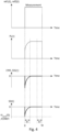
- Fig. 4 is a diagram that explains the reference light sensor signals ref1(t) and ref2(t), the fluorescence sensor signal PL (t), the CMR signal CMR_SIG(t), and the detection signal SD(t).
- the reference light sensor signals ref1(t) and ref2(t) are substantially rectangular pulse signals during the irradiation period.
- the fluorescence sensor signal PL(t) becomes a pulse signal that gradually rises and converges to a constant level during the irradiation period.
- the CMR signal CMR_SIG(t) is obtained by the common mode rejection.
- the arithmetic part 42 calculates and generates the detection signal SD(t) that is proportional to ⁇ cont (t) from the digitized CMR signal CMR_SIG(t) and the digitized reference light sensor signal ref2(t) and derives the measurement value (that is, for instance, a magnetic flux density or a waveform of the magnetic field) of the measured field based on the detection signal SD(t).
- the arithmetic part 42 performs digital filter processing for noise removal with respect to the digitized CMR signal CMR_SIG(t) or the detection signal SD(t) .
- the arithmetic part 42 applies a window function to the digitized CMR signal CMR_SIG(t) or the detection signal SD(t) in the digital filter processing and attenuates a high frequency component (a noise component with a high frequency) of the signal.
- the window function is an FIR (Finite Impulse Response) filter.
- Fig. 5 is a diagram that shows an example of a frequency characteristic of the window function.
- the above-mentioned window function has, for instance, a frequency characteristic shown in Fig. 5 and attenuates a high frequency noise component (in this case, components of about 10 kHz or more.
- the arithmetic part 42 executes noise removal processing separately from the above-mentioned digital filter processing.
- the arithmetic part 42 (a) respectively integrates (adds up) values of the digitized CMR signals that are obtained a plurality of times (with a predetermined number of samplings) at a former part (a first half) and a latter part (a second half) of the irradiation period of the excitation light, and (b) calculates a difference between an integrated value (a total sum or an average) of the CMR signals with respect to the former part and an integrated value (a total sum or an average) of the CMR signals with respect to the latter part so as to remove the noise components in the CMR signals.
- the analog/digital converter 26 operates faster than the analog/digital converter 27, and the analog/digital converter 27 performs digitizing with higher precision than the analog/digital converter 26.
- the analog/digital converter 26 converts an input analog signal into a 20-bit digital signal at, for instance, 200M samples/sec
- the analog/digital converter 27 converts an input analog signal into a 24-bit digital signal at, for instance, 100k samples/sec.
- the CMR signal that is converted from analog to digital by the analog/digital converter 26 changes relatively quickly, the CMR signal is sampled by the high-speed analog/digital converter 26, and as mentioned above, the noise removal based on a plurality of samples (samplings) is performed.
- the reference light sensor signal ref2 that is converted from analog to digital by the analog/digital converter 27 is used for the calculation in order to theoretically remove the influence of the noise component I noise of the excitation light in the CMR signal.
- the reference light sensor signal ref2 is sampled by the analog/digital converter 27 having relatively high precision.
- Fig. 6 is a flow diagram that explains the operation (that is, a measurement method) of the measurement device according to the embodiment shown in Fig. 1 .
- the sensor part 10 is arranged at a measurement position of the measured field. Note that measurements may be respectively performed at a plurality of measurement positions while scanning the sensor part 10.
- the measurement control part 41 causes the light emitting device 12 to emit the excitation light and causes the high frequency magnetic field generator 2 to transmit a microwave according to a predetermined measurement sequence (step S1).
- the light receiving device 13 outputs the fluorescence sensor signal PL (an analog signal), and the light receiving devices 23 and 24 respectively output the reference light sensor signals ref1 and ref2 (analog signals) (Step S2).
- the CMR arithmetic part 25 outputs the CMR signal CMR_SIG(t) from the fluorescence sensor signal PL(t) and the reference light sensor signal ref1, and the CMR signal CMR_SIG(t) is digitized by the analog/digital converter 26 (steps S3 and S4).
- the reference light sensor signal ref2 is digitized by the analog/digital converter 27 (step S4).
- the arithmetic part 42 removes the high frequency noise component (for instance, components of 10 kHz or more) from the CMR signal CMR_SIG(t) by applying the window function to the CMR signal (step S5), and further, performs integrations (additions) and differential actions with respect to a plurality of values of the CMR signals CMR_SIG(t) sampled several times (for instance, 1000 times) so as to remove the relatively low frequency noise component (for instance, components of several kHz to 10 kHz) (step S6).
- the high frequency noise component for instance, components of 10 kHz or more
- the arithmetic part 42 derives the value of the detection signal SD(t) based on the value of the CMR signal that is obtained by removing the noise as mentioned above and the value of the reference light sensor signal ref2 (step S7) . From the value of the detection signal SD(t), the arithmetic part 42 derives the measurement value of the measured field at the measurement position and at the measurement timing (an execution timing of the measurement sequence) (step S7).
- the high frequency magnetic field generator 2 performs the electron spin quantum operation with respect to the magnetic resonance member 1 using the microwave.
- the electron spin quantum state changes in correspond with the measured field and the electron spin quantum operation can be performed by using the microwave.
- the light emitting device 12 emits the excitation light to irradiate the magnetic resonance member 1.
- the light receiving device 13 receives the fluorescence that is emitted by the magnetic resonance member 1 in correspond with the excitation light and generates the fluorescence sensor signal corresponding to the intensity of the fluorescence.
- the CMR arithmetic part 25 performs the common mode rejection on (with respect to) the fluorescence sensor signal based on the reference light sensor signal generated by receiving the reference light that is obtained by branching the excitation light.
- the CMR arithmetic part 25 generates the CMR signal based on the common mode rejection.
- the analog/digital converter 26 digitizes the CMR signal.
- the analog/digital converter 27 digitizes the reference light sensor signal that is generated by receiving the reference light that is obtained by branching the above-mentioned excitation light.
- the arithmetic processing device 31 generates the detection signal based on the digitized CMR signal and the digitized reference light sensor signal and derives the measurement value of the measured field based on the detection signal.
- the CMR arithmetic part 25 performs the above-mentioned common mode rejection in consideration of the nonlinearity of the level of the fluorescence sensor signal with respect to the amount of the above-mentioned excitation light.
- the arithmetic processing device 31 performs the digital filter processing for the noise removal on (with respect to) the digitized CMR signal or the detection signal.
- the measurement accuracy is improved. Furthermore, because the nonlinearity of the level of the fluorescence sensor signal with respect to the amount of the above-mentioned excitation light is considered, the measurement accuracy is improved.
- the magnetic field measurement is performed based on the optically detected magnetic resonance.
- a temperature measurement can also be performed in the same manner. It is also possible to perform a current measurement based on the magnetic field obtained by the magnetic field measurement.
- the reference light for calculating the detection signal using the above-mentioned reference light sensor signal is branched from the excitation light.
- the reference light that is branched for the common mode rejection may also be used as the reference light for calculating the detection signal using the above-mentioned reference light sensor signal.
- the above-mentioned reference light sensor signals ref1 and ref2 are separately generated, it is also possible that one reference light sensor signal ref is generated and used as the above-mentioned reference light sensor signals ref1 and ref2.
- the window function is applied to the CMR signal.
- the window function may be applied to the detection signal.
- the differential amplifier 25b may be provided in separation of the analog/digital converter 26 or may be built in the analog/digital converter 26.
- the present invention can be applicable to, for instance, a measurement device that uses optically detected magnetic resonance.
Landscapes
- Physics & Mathematics (AREA)
- Health & Medical Sciences (AREA)
- General Physics & Mathematics (AREA)
- Biochemistry (AREA)
- Life Sciences & Earth Sciences (AREA)
- Chemical & Material Sciences (AREA)
- Analytical Chemistry (AREA)
- General Health & Medical Sciences (AREA)
- Immunology (AREA)
- Pathology (AREA)
- Optics & Photonics (AREA)
- Nuclear Medicine, Radiotherapy & Molecular Imaging (AREA)
- Condensed Matter Physics & Semiconductors (AREA)
- High Energy & Nuclear Physics (AREA)
- Investigating, Analyzing Materials By Fluorescence Or Luminescence (AREA)
Applications Claiming Priority (2)
| Application Number | Priority Date | Filing Date | Title |
|---|---|---|---|
| JP2021188931A JP7703149B2 (ja) | 2021-11-19 | 2021-11-19 | 測定装置および測定方法 |
| PCT/JP2022/034969 WO2023089944A1 (ja) | 2021-11-19 | 2022-09-20 | 測定装置および測定方法 |
Publications (2)
| Publication Number | Publication Date |
|---|---|
| EP4435409A1 true EP4435409A1 (de) | 2024-09-25 |
| EP4435409A4 EP4435409A4 (de) | 2025-11-19 |
Family
ID=86396784
Family Applications (1)
| Application Number | Title | Priority Date | Filing Date |
|---|---|---|---|
| EP22895230.5A Pending EP4435409A4 (de) | 2021-11-19 | 2022-09-20 | Messvorrichtung und messverfahren |
Country Status (4)
| Country | Link |
|---|---|
| US (1) | US20240410843A1 (de) |
| EP (1) | EP4435409A4 (de) |
| JP (1) | JP7703149B2 (de) |
| WO (1) | WO2023089944A1 (de) |
Families Citing this family (3)
| Publication number | Priority date | Publication date | Assignee | Title |
|---|---|---|---|---|
| JP2025035467A (ja) * | 2023-09-01 | 2025-03-13 | 国立大学法人京都大学 | 核磁気共鳴信号の測定方法および核磁気共鳴装置 |
| WO2025204000A1 (ja) * | 2024-03-26 | 2025-10-02 | スミダ電機株式会社 | 測定装置および測定方法 |
| CN118258432B (zh) * | 2024-05-30 | 2024-08-23 | 安徽省国盛量子科技有限公司 | 一种基于差分降噪的量子传感器、电流互感器及检测方法 |
Family Cites Families (7)
| Publication number | Priority date | Publication date | Assignee | Title |
|---|---|---|---|---|
| JP2004274426A (ja) | 2003-03-10 | 2004-09-30 | Nippon Telegr & Teleph Corp <Ntt> | トランスコンダクタンスアンプ回路 |
| JP4486433B2 (ja) | 2004-07-29 | 2010-06-23 | 浜松ホトニクス株式会社 | 吸収計測装置 |
| EP2784521B1 (de) * | 2013-03-28 | 2019-04-17 | Fraunhofer-Gesellschaft zur Förderung der angewandten Forschung e.V. | Sensoranordnung und Verfahren |
| US10712408B2 (en) * | 2016-11-08 | 2020-07-14 | Massachusetts Institute Of Technology | Methods and apparatus for optically detecting magnetic resonance |
| US20180267114A1 (en) | 2016-12-20 | 2018-09-20 | Board Of Regents Of The University Of Texas System | Adjustable coil holder and an imaging device including same |
| JP7115672B2 (ja) | 2018-02-09 | 2022-08-09 | 国立研究開発法人産業技術総合研究所 | センサ装置 |
| GB2580931A (en) | 2019-01-30 | 2020-08-05 | Univ Warwick | Defect centre-based sensor |
-
2021
- 2021-11-19 JP JP2021188931A patent/JP7703149B2/ja active Active
-
2022
- 2022-09-20 WO PCT/JP2022/034969 patent/WO2023089944A1/ja not_active Ceased
- 2022-09-20 US US18/701,719 patent/US20240410843A1/en active Pending
- 2022-09-20 EP EP22895230.5A patent/EP4435409A4/de active Pending
Also Published As
| Publication number | Publication date |
|---|---|
| WO2023089944A1 (ja) | 2023-05-25 |
| JP7703149B2 (ja) | 2025-07-07 |
| US20240410843A1 (en) | 2024-12-12 |
| EP4435409A4 (de) | 2025-11-19 |
| JP2023075802A (ja) | 2023-05-31 |
Similar Documents
| Publication | Publication Date | Title |
|---|---|---|
| EP4435409A1 (de) | Messvorrichtung und messverfahren | |
| JP5333370B2 (ja) | ガス濃度測定装置 | |
| EP3591419B1 (de) | Magnetfeldmessvorrichtung und magnetfeldmessverfahren | |
| EP4083647B1 (de) | Messvorrichtung und messverfahren | |
| JP5455721B2 (ja) | テラヘルツ波測定装置及び測定方法 | |
| US4600306A (en) | Apparatus for measuring the luminous lifetime of a sample | |
| EP4382944A1 (de) | Messvorrichtung und messverfahren | |
| EP3674690A1 (de) | Analysevorrichtung, programm für eine analysevorrichtung und analyseverfahren | |
| CN114324125B (zh) | 一种粒子计数传感器及控制该传感器的方法、装置及介质 | |
| EP4563991A1 (de) | Messvorrichtung und messverfahren | |
| EP4435455A1 (de) | Digitalisierungsvorrichtung und digitalisierungsverfahren | |
| EP4657104A1 (de) | Messvorrichtung und messverfahren | |
| Puljić et al. | Lifetime measurement of the 5 s 5 p 1 P 1 state in strontium | |
| JP2025149785A (ja) | 測定装置および測定方法 | |
| WO2025204000A1 (ja) | 測定装置および測定方法 | |
| JPH06138231A (ja) | 距離測定装置 | |
| JP2022161376A (ja) | 電子スピン共鳴測定装置 | |
| JP3203829B2 (ja) | センサー回路 | |
| JP3039822B2 (ja) | 信号波形検出装置 | |
| KR100357728B1 (ko) | 전자 빔 테스터 및 전자 빔 테스터 설정 방법 | |
| SU529436A1 (ru) | Способ измерени напр женности магнитного пол | |
| Zhu | A rapid-scan optical interferometric cross-correlator for time-resolved laser spectroscopy | |
| Damm et al. | Measurement conditions for continuously recording picosecond pump-and-probe spectrometers | |
| Macias-Bobadilla et al. | Digital phase-analyzer for low frequency applications based on reconfigurable hardware | |
| JPH04268457A (ja) | 電圧測定装置 |
Legal Events
| Date | Code | Title | Description |
|---|---|---|---|
| STAA | Information on the status of an ep patent application or granted ep patent |
Free format text: STATUS: THE INTERNATIONAL PUBLICATION HAS BEEN MADE |
|
| PUAI | Public reference made under article 153(3) epc to a published international application that has entered the european phase |
Free format text: ORIGINAL CODE: 0009012 |
|
| STAA | Information on the status of an ep patent application or granted ep patent |
Free format text: STATUS: REQUEST FOR EXAMINATION WAS MADE |
|
| 17P | Request for examination filed |
Effective date: 20240611 |
|
| AK | Designated contracting states |
Kind code of ref document: A1 Designated state(s): AL AT BE BG CH CY CZ DE DK EE ES FI FR GB GR HR HU IE IS IT LI LT LU LV MC MK MT NL NO PL PT RO RS SE SI SK SM TR |
|
| DAV | Request for validation of the european patent (deleted) | ||
| DAX | Request for extension of the european patent (deleted) | ||
| A4 | Supplementary search report drawn up and despatched |
Effective date: 20251020 |
|
| RIC1 | Information provided on ipc code assigned before grant |
Ipc: G01N 21/64 20060101AFI20251014BHEP Ipc: G01N 24/00 20060101ALI20251014BHEP Ipc: G01R 33/26 20060101ALI20251014BHEP Ipc: G01R 33/32 20060101ALN20251014BHEP |