EP4435366B1 - Echangeur de chaleur pour un lit de matière solide - Google Patents
Echangeur de chaleur pour un lit de matière solide Download PDFInfo
- Publication number
- EP4435366B1 EP4435366B1 EP23163005.4A EP23163005A EP4435366B1 EP 4435366 B1 EP4435366 B1 EP 4435366B1 EP 23163005 A EP23163005 A EP 23163005A EP 4435366 B1 EP4435366 B1 EP 4435366B1
- Authority
- EP
- European Patent Office
- Prior art keywords
- gas
- heat exchanger
- cylinder wall
- chamber
- bulk material
- Prior art date
- Legal status (The legal status is an assumption and is not a legal conclusion. Google has not performed a legal analysis and makes no representation as to the accuracy of the status listed.)
- Active
Links
Images

Classifications
-
- F—MECHANICAL ENGINEERING; LIGHTING; HEATING; WEAPONS; BLASTING
- F28—HEAT EXCHANGE IN GENERAL
- F28C—HEAT-EXCHANGE APPARATUS, NOT PROVIDED FOR IN ANOTHER SUBCLASS, IN WHICH THE HEAT-EXCHANGE MEDIA COME INTO DIRECT CONTACT WITHOUT CHEMICAL INTERACTION
- F28C3/00—Other direct-contact heat-exchange apparatus
- F28C3/10—Other direct-contact heat-exchange apparatus one heat-exchange medium at least being a fluent solid, e.g. a particulate material
- F28C3/12—Other direct-contact heat-exchange apparatus one heat-exchange medium at least being a fluent solid, e.g. a particulate material the heat-exchange medium being a particulate material and a gas, vapour, or liquid
- F28C3/14—Other direct-contact heat-exchange apparatus one heat-exchange medium at least being a fluent solid, e.g. a particulate material the heat-exchange medium being a particulate material and a gas, vapour, or liquid the particulate material moving by gravity, e.g. down a tube
-
- B—PERFORMING OPERATIONS; TRANSPORTING
- B29—WORKING OF PLASTICS; WORKING OF SUBSTANCES IN A PLASTIC STATE IN GENERAL
- B29B—PREPARATION OR PRETREATMENT OF THE MATERIAL TO BE SHAPED; MAKING GRANULES OR PREFORMS; RECOVERY OF PLASTICS OR OTHER CONSTITUENTS OF WASTE MATERIAL CONTAINING PLASTICS
- B29B13/00—Conditioning or physical treatment of the material to be shaped
- B29B13/02—Conditioning or physical treatment of the material to be shaped by heating
- B29B13/021—Heat treatment of powders
-
- B—PERFORMING OPERATIONS; TRANSPORTING
- B29—WORKING OF PLASTICS; WORKING OF SUBSTANCES IN A PLASTIC STATE IN GENERAL
- B29B—PREPARATION OR PRETREATMENT OF THE MATERIAL TO BE SHAPED; MAKING GRANULES OR PREFORMS; RECOVERY OF PLASTICS OR OTHER CONSTITUENTS OF WASTE MATERIAL CONTAINING PLASTICS
- B29B13/00—Conditioning or physical treatment of the material to be shaped
- B29B13/06—Conditioning or physical treatment of the material to be shaped by drying
- B29B13/065—Conditioning or physical treatment of the material to be shaped by drying of powder or pellets
-
- B—PERFORMING OPERATIONS; TRANSPORTING
- B29—WORKING OF PLASTICS; WORKING OF SUBSTANCES IN A PLASTIC STATE IN GENERAL
- B29B—PREPARATION OR PRETREATMENT OF THE MATERIAL TO BE SHAPED; MAKING GRANULES OR PREFORMS; RECOVERY OF PLASTICS OR OTHER CONSTITUENTS OF WASTE MATERIAL CONTAINING PLASTICS
- B29B9/00—Making granules
- B29B9/16—Auxiliary treatment of granules
-
- C—CHEMISTRY; METALLURGY
- C08—ORGANIC MACROMOLECULAR COMPOUNDS; THEIR PREPARATION OR CHEMICAL WORKING-UP; COMPOSITIONS BASED THEREON
- C08G—MACROMOLECULAR COMPOUNDS OBTAINED OTHERWISE THAN BY REACTIONS ONLY INVOLVING UNSATURATED CARBON-TO-CARBON BONDS
- C08G63/00—Macromolecular compounds obtained by reactions forming a carboxylic ester link in the main chain of the macromolecule
- C08G63/02—Polyesters derived from hydroxycarboxylic acids or from polycarboxylic acids and polyhydroxy compounds
- C08G63/12—Polyesters derived from hydroxycarboxylic acids or from polycarboxylic acids and polyhydroxy compounds derived from polycarboxylic acids and polyhydroxy compounds
- C08G63/16—Dicarboxylic acids and dihydroxy compounds
- C08G63/18—Dicarboxylic acids and dihydroxy compounds the acids or hydroxy compounds containing carbocyclic rings
- C08G63/181—Acids containing aromatic rings
- C08G63/183—Terephthalic acids
-
- C—CHEMISTRY; METALLURGY
- C08—ORGANIC MACROMOLECULAR COMPOUNDS; THEIR PREPARATION OR CHEMICAL WORKING-UP; COMPOSITIONS BASED THEREON
- C08G—MACROMOLECULAR COMPOUNDS OBTAINED OTHERWISE THAN BY REACTIONS ONLY INVOLVING UNSATURATED CARBON-TO-CARBON BONDS
- C08G63/00—Macromolecular compounds obtained by reactions forming a carboxylic ester link in the main chain of the macromolecule
- C08G63/78—Preparation processes
- C08G63/785—Preparation processes characterised by the apparatus used
-
- C—CHEMISTRY; METALLURGY
- C08—ORGANIC MACROMOLECULAR COMPOUNDS; THEIR PREPARATION OR CHEMICAL WORKING-UP; COMPOSITIONS BASED THEREON
- C08G—MACROMOLECULAR COMPOUNDS OBTAINED OTHERWISE THAN BY REACTIONS ONLY INVOLVING UNSATURATED CARBON-TO-CARBON BONDS
- C08G63/00—Macromolecular compounds obtained by reactions forming a carboxylic ester link in the main chain of the macromolecule
- C08G63/88—Post-polymerisation treatment
Definitions
- the present invention relates to a method and a device for the thermal treatment of a solid bed, for example polycondensates, in particular polyesters such as polyethylene terephthalate (PET).
- a heat exchanger according to the preamble of claim 1.
- Such a heat exchanger is made of US 6,405,454 known.
- Solid beds often require thermal treatment such as heating, drying, or cooling.
- thermal treatment such as heating, drying, or cooling.
- PET polyethylene terephthalate
- the semi-crystalline PET is heated uniformly and in a controlled manner in a preheater to a temperature that is in the range of the temperature used in solid-state post-condensation or just below.
- Conventional heat exchangers consist of a shaft-like container into which the material to be treated is continuously introduced so that it reaches an essentially constant level in the container. It sinks evenly under the influence of gravity, with a process gas flowing through it.
- the process gas is usually introduced and discharged through roof-shaped internals arranged transversely to the direction of movement of the solid bed. In this way, the solid bed is evenly exposed to the process gas. The pressure losses are comparatively low.
- the roof-shaped fittings cause a certain loosening within the solid material bed, thereby reducing the risk of agglomerates and bridges forming, which occurs particularly during the treatment of plastic granules.
- This heat exchanger is still not optimal.
- the process gas must be introduced through gas inlets across the entire height of the heat exchanger and guided through the centrally located channel containing the solid bed.
- the achieved heat exchange with the solid bed is also limited.
- the gas required for thermal treatment is directed into an inner gas chamber located within the treatment chamber containing the solid bed.
- the gas is distributed evenly within the inner gas chamber. Since the inner gas chamber is sealed at the top, the gas can only pass through the inner cylindrical wall of the heat exchanger, which forms the boundary between the inner gas chamber and the treatment chamber.
- the inner cylindrical wall is permeable to gas but essentially prevents the passage of particles from the solid bed.
- "essentially” means that at most 0.001% of all particles of the solid bed can pass through the corresponding cylinder wall.
- the gas flows through the solids in the treatment chamber essentially horizontally and reaches the outer cylinder wall, which forms the boundary between the treatment chamber and an external gas chamber.
- the outer cylinder wall is gas-permeable, but essentially does not allow the Passage of particles from the solid bed.
- the gas is then discharged from the outer gas space to the heat exchanger.
- the heat exchanger according to the invention can be supplied with a larger amount of gas because the inner cylinder wall has a height that is greater than the height of the outer cylinder wall. Although the dimensions of the heat exchanger remain unchanged (the treatment chamber and the gas chambers are located inside the heat exchanger), more gas can be passed through the inner gas chamber into the treatment chamber.
- the heat exchanger according to the invention is not particularly limited in terms of its dimensions and can have usual dimensions for a heat exchanger, for example a diameter of up to 3 m and a height of up to 10 m.
- the heat exchanger according to the invention is defined by a shell.
- the shell is preferably rectangular or circular in cross-section and made of a suitable material such as a metal, for example, steel.
- the two gas chambers and the treatment chamber are provided as described below.
- the inner gas chamber serves to supply process gas to the heat exchanger. It is a cylindrical chamber whose cylinder axis preferably coincides with a rotational axis of the heat exchanger. In other words, the inner Gas space arranged symmetrically around a rotation axis of the heat exchanger.
- the inner gas space is connected to a gas inlet, preferably located in the lower region of the heat exchanger.
- the "lower region” here refers to the lower half, preferably the lower third, and particularly preferably the lower quarter of the heat exchanger.
- gas inlet can be opened and closed, for example, using a valve.
- the process gas enters the inner gas space through the gas inlet.
- the process gas rises in this inner gas space.
- the gas inlet can also be located elsewhere.
- the upper end of the inner gas space is closed, which is why the introduced gas is distributed in the inner gas space.
- the inner gas space has a conical end section that tapers towards the upper end of the heat exchanger.
- the inner gas space is delimited by an inner cylinder wall.
- This wall is designed to be gas-permeable, but the particles of the solid bed are essentially unable to pass through the cylinder wall.
- An exemplary design of the inner cylinder wall is described below.
- a hollow cylindrical treatment chamber is arranged around the inner gas chamber.
- the radius of the treatment chamber is larger than the radius of the inner gas chamber, so that the treatment chamber completely surrounds the inner gas chamber.
- the treatment chamber is bounded on the inside by the inner cylinder wall and on the outside by an outer cylinder wall. This is also designed to be gas-permeable, but the particles of the solid bed are essentially unable to pass through the cylinder wall.
- An exemplary design of the outer cylinder wall is described below.
- the treatment chamber serves to receive and thermally treat a solid bed.
- the treatment chamber is connected to a product inlet in the upper area of the heat exchanger and at least one product outlet in the lower area of the heat exchanger (as defined above).
- the "upper area” here refers to the upper half, preferably the upper third, and particularly preferably the upper quarter of the heat exchanger.
- product inlets and outlets can be used. These product inlets and outlets can preferably be opened and closed to allow controlled feeding and discharge of the solids. Examples include rotary valves.
- the heat exchanger may have more than one product outlet, for example two product outlets.
- the treatment chamber is shaped like a substantially vertically oriented hollow cylinder and is surrounded by an outer gas chamber.
- the radius of the treatment chamber is smaller than the radius of the outer gas chamber, so that the outer gas chamber completely surrounds the treatment chamber.
- the outer gas chamber serves to discharge the process gas after it has undergone heat exchange with the solid bed in the treatment chamber.
- the outer gas chamber is connected to a gas outlet that leads through the shell.
- the position of the gas outlet is not particularly restricted.
- the gas outlet can be located in the upper area of the heat exchanger (as defined above).
- any standard gas outlet can be used.
- the gas outlet can be opened and closed, for example, using a valve.
- the outer gas space is limited inwards by the outer cylinder wall and outwards by the shell of the heat exchanger.
- the outer gas space has a conical end section that tapers toward the lower end of the heat exchanger. It is particularly preferred that an outlet opening is provided at the lower end of the conically tapered end section.
- the inner cylinder wall and the outer cylinder wall are gas-permeable, but designed in such a way that the particles of the solid bed cannot essentially pass through the cylinder walls.
- Such walls are well known. Examples include walls made of a A suitable material, such as a metal, preferably steel, which has openings through which gas can pass.
- the size of the openings is such that particles of a solid bed essentially cannot pass through, since the particle size exceeds the size of the openings.
- the inner cylinder wall and the outer cylinder wall are formed from a gap plate, which is constructed from a support structure and profiled bars arranged thereon.
- the profiled bars are preferably arranged on the side of the treatment chamber (i.e., on the side of the corresponding cylinder wall facing the treatment chamber) and are spaced apart such that the particles of the solid bed cannot essentially pass through.
- the arrangement of the profile bars on the support structure can be vertical or horizontal.
- the profile bars of the outer cylinder wall are arranged vertically toward the treatment chamber (i.e., on the side of the cylinder wall facing the treatment chamber). This enables better product flow along the profile bars.
- the profile bars of the inner cylinder wall are particularly preferably arranged horizontally toward the treatment chamber (i.e., on the side of the cylinder wall facing the treatment chamber).
- the individual profile bars are preferably conical and arranged on the support structure such that the wider part faces the treatment room and the narrower part faces the support structure.
- the advantage of such an arrangement is that any Small particles that are pressed between the profile bars are eventually pushed through the bars by the prevailing product pressure, fall into the outer gas space and there reach the conical end section and can be removed via an outlet opening.
- a key feature of the invention is that the inner cylinder wall has a height greater than the height of the outer cylinder wall. This allows the heat exchanger according to the invention to be fed with a larger amount of gas. Although the dimensions of the heat exchanger remain unchanged (the treatment chamber and the gas chambers are located inside the heat exchanger), more gas can be passed through the inner gas chamber into the treatment chamber. As a result, a more efficient heat exchange treatment can be carried out.
- the height of the inner cylinder wall is 1-50%, preferably 5-40%, particularly preferably 10-30% greater than the height of the outer cylinder wall.
- the heat exchanger according to the invention can be used to thermally treat a bed of solids. This is preferably a thermal treatment such as heating, drying, or cooling. While during heating or drying, the process gas has a temperature that is above the temperature of the bed of solids, during cooling, the bed of solids has a temperature that is above the temperature of the process gas.
- a thermal treatment such as heating, drying, or cooling. While during heating or drying, the process gas has a temperature that is above the temperature of the bed of solids, during cooling, the bed of solids has a temperature that is above the temperature of the process gas.
- Such heat exchange processes are well known.
- the present invention further relates to a plant for producing a polycondensate, preferably polyethylene terephthalate, comprising a heat exchanger according to the invention, which is preferably arranged as a preheater upstream of an SSP reactor for carrying out a solid-phase post-condensation.
- a polycondensate preferably polyethylene terephthalate
- a heat exchanger according to the invention which is preferably arranged as a preheater upstream of an SSP reactor for carrying out a solid-phase post-condensation.
- the heat exchanger according to the invention is preferably used as a preheater upstream of an SSP reactor for carrying out a solid-phase post-condensation.
- the solid bed is a bed of individual, preferably free-flowing particles.
- the individual particles preferably have a substantially uniform particle size distribution. Nevertheless, the presence of individual microparticles cannot be ruled out. Particles that have a diameter of less than half the average particle diameter in at least one dimension are referred to as microparticles.
- the solid bed is preferably a bed of particles of polycondensate, preferably polyester such as polyethylene terephthalate homopolymer or a copolymer thereof.
- Suitable polycondensates include crystallizable, thermoplastic polycondensates, such as polyamides, polycarbonates and polyesters, including polyhydroxyalkanoates, polylactides or their copolymers, which are obtained by a polycondensation reaction with elimination of a low-molecular reaction product.
- the polycondensation can take place directly between the Monomers or via an intermediate, which is subsequently converted by transesterification, whereby the transesterification can again occur with the elimination of a low-molecular-weight reaction product or by ring-opening polymerization.
- the resulting polycondensate is essentially linear, although a small number of branches may occur.
- Semi-crystalline polycondensate granules refer to polycondensate granules that have both amorphous zones and zones with a crystalline structure.
- Polycondensates of a polymer type are each obtained from the same main monomers. A limited amount of additional monomers, so-called comonomers, can be used.
- Polyamides are polymers which are usually obtained by polycondensation of a diamine component with the general structure H 2 NR 1 -NH 2 and a dicarboxylic acid component with the general structure HOOC-R 2 -COOH, where R 1 and R 2 are usually optionally substituted, linear or branched aliphatic hydrocarbons having 1 to 15 carbon atoms, aromatic or heteroaromatic hydrocarbons with 1 to 3 aromatic rings, cyclic hydrocarbons with 4 to 10 carbon atoms or heterocyclic hydrocarbons with 1 to 3 oxygen or nitrogen atoms and 3 to 10 carbon atoms.
- dicarboxylic acid its corresponding dicarboxylic acid halide, preferably dicarboxylic acid chloride, can also be used.
- polyamides examples include PA-6,6, which is made from hexamethylenediamine and adipic acid, or PA-mXD6, which is made from m-xylylenediamine and adipic acid.
- Polyamides are also polymers with repeating amide groups having the general structure H-[N(H)-R-CO]x-OH, where R is usually an optionally substituted, linear or branched aliphatic hydrocarbon having 1 to 15 carbon atoms, an aromatic or heteroaromatic hydrocarbon having 1 to 3 aromatic rings, a cyclic hydrocarbon having 4 to 10 carbon atoms or a heterocyclic hydrocarbon having 1 to 3 oxygen or nitrogen atoms and 3 to 10 carbon atoms.
- R is usually an optionally substituted, linear or branched aliphatic hydrocarbon having 1 to 15 carbon atoms, an aromatic or heteroaromatic hydrocarbon having 1 to 3 aromatic rings, a cyclic hydrocarbon having 4 to 10 carbon atoms or a heterocyclic hydrocarbon having 1 to 3 oxygen or nitrogen atoms and 3 to 10 carbon atoms.
- Polyamides are also polymers produced by ring-opening polymerization from heterocyclic monomers with at least one amide group, such as polycaprolactam (PA6) produced from caprolactam.
- PA6 polycaprolactam
- Polyesters are polymers that are typically obtained by polycondensation of a diol component with the general structure HO-R1-OH and a dicarboxylic acid component with the general structure HOOC-R2-COOH, where R1 and R2 are typically optionally substituted, linear or branched aliphatic hydrocarbons having 1 to 15 carbon atoms, aromatic or heteroaromatic hydrocarbons with 1 to 3 aromatic rings, cyclic hydrocarbons with 4 to 10 carbon atoms, or heterocyclic hydrocarbons with 1 to 3 oxygen atoms and 3 to 10 carbon atoms. Typically, linear or cyclic diol components and aromatic or heterocyclic dicarboxylic acid components are used.
- polyesters are polyethylene terephthalate (PET), polybutylene terephthalate (PBT), polytrimethylene terephthalate (PTT), polyethylene furanoate (PEF), polytrimethylene furanoate (PTF), polybutylene succinate (PBS) and polyethylene naphthalate (PEN), which are used either as homopolymers or as copolymers.
- polyethylene terephthalate which is obtained from its monomers, a diol component and a dicarboxylic acid component.
- the diol component consists of ethylene glycol (1,2-ethanediol) as the main monomer
- the dicarboxylic acid component consists of terephthalic acid as the main monomer.
- Other linear, cyclic, or aromatic diol and dicarboxylic acid compounds can be used as comonomers.
- Typical comonomers are diethylene glycol (DEG), isophthalic acid (IPA), or 1,4-bishydroxymethylcyclohexane (CHDM).
- polyethylene furanoate which is obtained from its monomers, a diol component and a dicarboxylic acid component.
- the diol component consists of ethylene glycol (1,2-ethanediol) as the main monomer
- the dicarboxylic acid component consists of 2,5-furandicarboxylic acid as the main monomer.
- Other linear, cyclic, or aromatic diol and dicarboxylic acid compounds can be used as comonomers.
- Typical comonomers are diethylene glycol (DEG) or trimethylene glycol.
- Polyesters are also polymers with repeating ester groups having the general structure H-[OR-CO] x -OH, where R is usually an optionally substituted, linear or branched aliphatic hydrocarbon having 1 to 15 carbon atoms, an aromatic or heteroaromatic hydrocarbon having 1 to 3 aromatic rings, a cyclic hydrocarbon having 4 to 10 carbon atoms or a heterocyclic hydrocarbon with 1 to 3 oxygen or nitrogen atoms and 3 to 10 carbon atoms.
- R is usually an optionally substituted, linear or branched aliphatic hydrocarbon having 1 to 15 carbon atoms, an aromatic or heteroaromatic hydrocarbon having 1 to 3 aromatic rings, a cyclic hydrocarbon having 4 to 10 carbon atoms or a heterocyclic hydrocarbon with 1 to 3 oxygen or nitrogen atoms and 3 to 10 carbon atoms.
- polyhydroxyalkanoates with the general structure H-[OC(R)H-(CH 2 ) n -CO] x -OH, where R is usually a hydrogen or a linear or branched aliphatic hydrocarbon having 1 to 15 carbon atoms and n is 1 to 10.
- R is usually a hydrogen or a linear or branched aliphatic hydrocarbon having 1 to 15 carbon atoms and n is 1 to 10.
- Examples are poly-4-hydroxybutyrate and poly-3-hydroxyvalerate.
- polylactides with the general structure H-[OC(R)H-CO] x -OH, where R is usually a methyl group or an aliphatic hydrocarbon with 1 to 15 carbon atoms.
- polyglycolic acid with the general structure H-[O-CH 2 -CO] x -OH].
- Polyesters are also polymers which are produced by ring-opening polymerization from heterocyclic monomers having one ester group, such as polycaprolactone from caprolactone, or by ring-opening polymerization from heterocyclic monomers having at least two ester groups, such as polylactide from lactide.
- polylactide polylactic acid with the structure H-[OC(CH 3 )H-CO] x -OH. Due to the chirality of lactic acid, various forms of polylactic acid exist.
- Homopolymers include poly-L-lactide (PLLA), which is usually made from L,L-lactide, and poly-D-lactide (PDLA), which is usually made from D,D-lactide.
- Copolymers such as poly-(L-lactide-co-D,L-lactide) contain small amounts of lactide units with a chirality different from that of the main monomer.
- Polyesters can also be produced by biosynthesis by microorganisms or in plant cells, from which they are obtained by cell disruption.
- Suitable polycondensates can be crystallizable homopolymers. Despite the term homopolymer, a small proportion of comonomers can form during the manufacturing process. For example, the formation of diethylene glycol from ethylene glycol is known in the production of polyethylene terephthalate. However, many suitable polycondensates are crystallizable copolymers that contain a certain proportion of comonomer. The comonomers can be introduced into the polycondensate manufacturing process as part of the monomers, or they form as part of the manufacturing process, usually resulting in a random distribution. The comonomers can also be incorporated as blocks made from different monomers, resulting in so-called block copolymers.
- Typical amounts of one or more comonomers range from 1% to approximately 30% w/w. Due to the fact that in many cases an excessive amount of comonomer completely prevents crystallization, the maximum comonomer content can be limited to below 20% w/w, preferably below 10% w/w.
- Suitable polycondensates can be polymer mixtures containing any number and amount of different polymer types. A small amount of a polymer can act as a nucleating agent in polycondensates, thereby increasing their crystallization rate.
- Specific polycondensate mixtures can form interacting crystal structures with crystallization behavior that differs from the individual components.
- An example is a mixture of PDLA and PLLA, which forms a stereocomplex crystal structure with increased crystallinity.
- each polycondensate chain has chain-terminating groups, usually with the functionality of at least one of its monomers.
- a polyester chain may have one or more hydroxyl and/or carboxyl end groups.
- a polyamide chain may have one or more hydroxyl and/or amine end groups.
- Such end groups may be modified by a so-called endcapping reagent, or they may be modified by a degradation reaction.
- suitable polymers may have such modified end groups.
- the polycondensate can be a virgin material or a recyclate.
- Recyclates are polymers that are recycled from manufacturing and processing (post-industrial) or polymers that are collected and recycled after consumer use (post-consumer).
- Additives can be added to the polycondensate.
- Suitable additives include catalysts, dyes and pigments, UV blockers, processing aids, stabilizers, impact modifiers, chemical and physical blowing agents, fillers, nucleating agents, flame retardants, plasticizers, barrier or mechanical property-enhancing particles, reinforcing bodies such as spheres or fibers, and reactive substances, such as oxygen absorbers, acetaldehyde absorbers or molecular weight-increasing substances.
- the polycondensates described above can usually be produced in a melt polymerization up to a certain molecular weight and then converted into a solid bed in a granulation device for further thermal treatment.
- a polycondensate melt is fed as starting material to the granulation device for forming a polycondensate granulate.
- the production of a polycondensate melt is carried out using apparatus or reactors known in the art (e.g. Scheirs/Long (eds.), Modern Polyesters, Wiley 2003, especially p. 31-104 ).
- polymerization reactors in which polycondensates are produced in the liquid phase such as stirred tank reactors, cage reactors, or disc reactors, or equipment in which previously produced polycondensates are melted, such as extruders or kneaders, are suitable.
- Polycondensate melt production can be carried out continuously or batchwise. However, continuous processes are preferred for further processing.
- individual polycondensate strands are formed from the polycondensate melt.
- granules i.e. particles of defined shape and size
- the granulation techniques known in the art such as strand granulation, water ring granulation, underwater granulation or head granulation (also called hot face granulation)
- the polycondensate strands emerging from the melt channels are solidified and separated into a multitude of individual granules, whereby the Separation can occur before or after solidification.
- Separation occurs, for example, through spontaneous droplet formation, through the use of a liquid shearing medium, or through mechanical separation, particularly cutting. While droplet formation occurs spontaneously or through shearing medium at the nozzle outlet, cutting can occur either directly at the nozzle outlet or only after passing through a treatment section.
- the polycondensate melt is solidified by cooling with the aid of at least one liquid cooling medium or a combination of different liquid cooling media.
- liquid cooling media are liquids that have a high specific heat capacity, preferably greater than 2 kJ/(kg K), and a sufficiently high boiling point, preferably greater than 90°C, as well as that do not significantly attack or alter the polycondensate and do not leave any toxic residues in the polycondensate.
- a single liquid cooling medium is preferably used. Preference is given to water or ethylene glycol or mixtures thereof. Water is particularly preferred as the cooling medium.
- the polycondensate can, for example, flow through a section containing a process gas, particularly air or water mist, before entering the liquid cooling medium.
- a process gas particularly air or water mist
- other liquid media can also be used.
- cooling can take place before, during, or after the material is formed into granules.
- the liquid cooling medium has a temperature of more than 50°C when entering the granulation device. but at least 10°C below its boiling point.
- the temperature of the cooling medium according to this embodiment at atmospheric pressure is therefore 50°C to 90°C. Due to the pressure dependence of the boiling point, the suitable temperature of the liquid cooling medium increases with increased pressure in the fluid system. At lower pressures, the suitable temperature decreases, which is also the case in open systems with low external pressure.
- the liquid cooling medium preferably water, depending on the Tg of the polycondensate to be formed, has a temperature of less than 85°C, particularly preferably between 50°C and 80°C, especially preferably between 60°C and 75°C.
- the liquid cooling medium upon entering the granulation device, has a temperature below the glass transition temperature (also called the glass transition point, abbreviated Tg) of the polycondensate to be formed.
- Tg glass transition temperature
- the granules begin to stick together above the material's glass transition temperature, i.e., the particles adhere to one another to form agglomerates.
- the glass transition temperature of polyethylene terephthalate for example, is approximately 75°C to 82°C (depending on the comonomer content and the type of comonomers added).
- the glass transition temperature of a polycondensate can be determined using a DSC (digital scanning calorimetry) measurement.
- DSC digital scanning calorimetry
- Devices for DSC measurements are also well known and commercially available.
- An example is the Mettler DSC821.
- To measure the glass transition temperature of a polycondensate such as a polyester For example, 5-25 mg of a corresponding polymer sample is heated from 25°C to 290°C in a Mettler DSC821 instrument at a rate of 10°C/min. The sample is held at 290°C for 1 min, then rapidly cooled to room temperature and heated a second time at a rate of 10°C/min from 25°C to 290°C. The glass transition point (Tg) is determined from this second run. The inflection point of the corresponding signal in the DSC is used as Tg.
- the granules produced in this way should preferably have a defined granule shape, such as cylindrical, spherical, drop-shaped, spherical or a design shape, as for example in EP 0 541 674 proposed.
- the average granule size should be between 0.1 mm and 10 mm, preferably between 0.5 mm and 3.5 mm, and particularly preferably between 0.85 mm and 3 mm.
- the mean granule size is defined as the statistical mean of the mean granule diameter, which is calculated from the average of the granule height, length, and width (measurable using known methods).
- the granule size distribution should be kept within a narrow range.
- the standard deviation of the granule weights of 100 measured granules is preferably between 2 and 20%.
- the granulate is subjected to crystallization before entering the heat exchanger according to the invention for preheating.
- This crystallization can be a conventional crystallization or a direct crystallization.
- the granulate ie the solid bed
- the granulate can be subjected to direct crystallization in the heat exchanger according to the invention, as is clear from the EP-3 650 186 A1 is known.
- the granules are cooled after production to a temperature below the crystallization temperature, especially below the glass transition temperature Tg (e.g., to room temperature).
- Tg glass transition temperature
- the granules must be heated again to a temperature within the crystallization temperature range of the polycondensate. This can be achieved, for example, via a heated wall of the crystallization reactor, via heated internals in the crystallization reactor, by radiation, or by blowing in a hot process gas.
- the granules are not cooled to such an extent (e.g. to room temperature) that they have to be heated for subsequent crystallization, which requires a large amount of energy.
- the granules are preferably cooled to an average granule temperature that lies within the crystallization temperature range of the polycondensate. This is achieved by selecting the temperature of the cooling medium as described above and by selecting a correspondingly short residence time of the granules in the cooling medium.
- the cooling medium is preferably separated from the granules within 0.1 to 5 seconds, particularly preferably within 0.3 to 3 seconds after the addition of the cooling medium. Simultaneously with the cooling, the polycondensate granules can be conveyed to a further process step.
- the average granulate temperature refers to the mean value of the temperatures of the individual granules, whereby each granulate has an average temperature that results when the temperature profile in the granulate balances out without heat exchange to the outside.
- the suitable crystallization temperature range for polyethylene terephthalate is between 110 and 220 °C, for polyethylene furanoate between 110 and 190 °C, and for poly-L-lactide between 80 and 140 °C.
- the crystallization half-life (t1 ⁇ 2) is determined by isothermal crystallization using DSC (differential scanning calorimetry).
- the crystallization half-life corresponds to the time required at a given temperature to reach 50% of the achievable crystallinity.
- the minimum crystallization half-life (11 ⁇ 2 min) is the shortest crystallization half-life obtained within the crystallization temperature range.
- the granulate is cooled to a temperature below the crystallization temperature, in particular below the glass transition temperature Tg of about 78°C, or in the case of direct crystallization to a temperature in the Range from 110 to 180 °C, preferably between 115 °C and 160 °C and particularly preferably from 120 °C to 150 °C.
- PET polyethylene terephthalate
- the cooling medium After cooling to the desired temperature, the cooling medium is separated from the granules and thus dried.
- the granules are further treated (conditioned) in a liquid medium, for which the cooling medium or another liquid can be used directly.
- the separation of the granules from a liquid cooling medium can be carried out using separation devices known in the art as a drying device. These can be merely passive separation devices, such as grids or grates, through which the cooling medium can pass, but not the granules. Typically, active separation devices are used for at least part of the separation, whereby the separation can occur, for example, due to a gas flow, centrifugal force, impact, evaporation, or combinations thereof. Such devices are known, for example, as suction devices, impact dryers, or centrifugal dryers.
- the separation can be assisted by supplying a gas flow into the separation device, wherein the gas flow optionally comprises heated or dried gas, in particular air. A centrifugal dryer with an air supply is preferred.
- the granules are transferred from a unit for forming the granules described above via a connecting line to a unit for separating the cooling medium.
- the transfer of the granules into the separating device preferably takes place at a speed such that the granules do not cool below their crystallization temperature range.
- the flow rate of the granules in the connecting line can be adjusted by supply of air or another suitable gas into the connecting line.
- a temperature in the range of 100 to 200°C, preferably 110 to 160°C, and particularly preferably 120 to 150°C is preferably applied.
- the granules preferably remain in the dryer for a period of one-tenth of a second to 10 seconds.
- the granulate preferably has a temperature T GR in the range of 100-180°C, preferably from 120°C to 160°C, after leaving the dryer (separating device).
- the separating device has at least one inlet opening for feeding the granulate into the unit.
- the inlet opening can be, for example, an opening in the housing or the outlet from a pipe that leads into the housing.
- the separating device has at least one discharge opening for removing the granulate from the unit.
- the discharge opening can be, for example, an opening in the housing or the inlet to a pipe that leads out of the housing.
- the separating device has at least one discharge opening for removing the liquid cooling medium from the unit.
- a gas phase is present, which absorbs the evaporating cooling medium.
- This gas is preferably air.
- gases or gas mixtures with a lower oxygen content than air can also be used.
- the separating device is preferably not a closed unit.
- the separating device preferably has at least one An outlet opening for the discharge of gas, preferably air.
- the outlet opening of the separating device preferably opens into a gas discharge line in which a fan is arranged to circulate air through the separating device.
- the outlet opening is connected to a condenser for recovering liquid cooling medium from the discharged gas.
- the separation device can further comprise at least one inlet opening for introducing gas, preferably air.
- the inlet opening is preferably located at the opposite end of the dryer (separation device) to the outlet opening to ensure that the gas flows completely through the dryer (separation device).
- the inlet opening for introducing gas it is also possible for the inlet opening for introducing gas to be located not in the separation device, but in a downstream unit or a connecting line to a downstream unit.
- the gas is fed to the inlet via an intake filter.
- a fan can be arranged in the gas line leading to the inlet to circulate air through the separator. This fan can be provided in addition to the fan in the gas discharge line or replace it.
- the line leading to the inlet and the line leading from the outlet can be connected to form a closed circuit.
- the gas must be passed through a condenser before re-entering the separation device to separate the evaporated cooling medium contained in the gas.
- the system according to the invention preferably has a cooling medium circuit.
- the cooling medium is fed from a storage container (tank) into the molding unit (granulation device), preferably via a circulation pump and optionally a heat exchanger (for selectively heating or cooling the cooling medium).
- the cooling medium separated in the separating device or a possible condenser can be fed back into the storage container via a pipeline.
- the polycondensate granules After the polycondensate granules have been separated from the liquid cooling medium, they are transferred to the subsequent unit, which includes a crystallization chamber.
- Particularly suitable devices for crystallization are fluidized bed devices, such as those used in the EP-1 425 146 A2 Heating to crystallization temperature and subsequent crystallization can be carried out in one or more crystallization apparatuses.
- Crystallization can take place in one or more steps, and thus in one or more consecutive devices. Crystallization can be carried out continuously or batchwise. Optionally, crystallization can take place in two or more devices operating in parallel.
- the transfer to the subsequent crystallization unit is achieved by means of a connecting line which is arranged between the separating device and the subsequent crystallization unit and connects the discharge opening of the separating device with the inlet opening of the subsequent crystallization unit.
- the connecting line is preferably designed in such a way that an unhindered passage of the Polycondensate granules from the upstream unit to the downstream crystallization unit is ensured.
- a sieve is arranged between the separation device and the downstream crystallization unit. This sieve allows individual granules of the specified size to pass through unhindered, but retains granule agglomerates and oversized granules.
- a shut-off unit preferably a lock unit such as a rotary valve, is arranged between the separation device and the downstream unit. Multiple separation devices can be connected to a downstream unit.
- the connecting line can be connected as shown in the WO 2008/071278 described be connected to an intermediate storage facility into which the material is guided by a control device in the event of a fault and stored there under conditions (in particular lowering the granulate temperature below its glass transition point) under which agglomeration of the granulate does not occur.
- the separation device is connected to the subsequent crystallization unit in such a way that the granules can be transferred directly from the separation device to the subsequent crystallization unit.
- the granules to be treated are generally essentially amorphous, i.e. they have a degree of crystallization of less than 10%, preferably less than 5%.
- the polycondensate granules flow through the crystallization unit essentially from top to bottom, while a process gas flows through the crystallization unit in countercurrent or, alternatively, in crosscurrent or a combination of countercurrent and crosscurrent. If the heat exchanger according to the invention is used, the flow occurs in crosscurrent.
- Process gases that can be used include, for example, air, steam, or inert gases such as nitrogen, noble gases such as argon, or CO2 .
- the process gas can comprise a mixture of several process gases.
- the process gas can contain additives that either reactively affect the polycondensate to be treated, have a swelling effect on the polycondensate, or passively deposit on the polycondensate granules to be treated.
- the oxygen content of the process gas should be less than 0.1 wt.%, preferably less than 0.05 wt.%, and particularly preferably less than 0.02 wt.%.
- the polycondensate granules are present therein as a fixed bed, which comprises the fixed bed moved in continuous operation.
- the crystallization unit is arranged below the device for separating the cooling medium/drying.
- the heat exchanger according to the invention is used as a crystallization unit for direct crystallization.
- the granules are crystallized in the crystallization unit either passively without external heat input (so-called latent heat crystallization) or crystallized by external energy input using the hot process gas (so-called active direct crystallization).
- the process gas is fed into the crystallization unit at a temperature T Gas that is greater than the sum of the granule temperature T GR and the temperature increase T KR occurring in the crystallization unit due to the heat of crystallization released, i.e. T Gas > (T GR + T KR ).
- the gas temperature T Gas is therefore above the average granule temperature that the polycondensate granules would reach in the crystallization unit without external energy input, which has the advantage that the polycondensate granules can be adjusted to a constant and defined outlet temperature.
- a heat exchanger according to the invention is preferably arranged downstream of the crystallization unit in the plant according to the invention.
- the granules are heated in the heat exchanger (even if it is used as a crystallization unit in the variant described above) to the temperature required for a further thermal treatment step, for example, an SSP reaction.
- a further thermal treatment step is arranged downstream of the heat exchanger according to the invention. A different subsequent process or no further step at all can then follow.
- the process according to the invention is carried out in the heat exchanger according to the invention.
- the The mass ratio of gas stream to product stream in the heat exchanger according to the invention should be greater than 1 and less than 10, preferably greater than 2 and less than 10 and particularly preferably greater than 3 and less than 7.
- the solid bed introduced into the treatment chamber through the product inlet of the heat exchanger is cross-flowed by gas from the inner gas chamber, which then enters the outer process chamber and is discharged.
- the gas has a temperature that differs from the temperature of the solid bed.
- the process gas is hotter than the solid bed, but at least 10°C cooler than the melting point of the particles in the solid bed.
- the gas preferably flows through the inner cylinder wall of the inner gas space at a bore velocity in the range of 0.3 to 0.8 m/s, in particular 0.4 to 0.7 m/s. Accordingly, the gas flows through the outer cylinder wall at a bore velocity of 0.2 to 0.6 m/s, in particular more than 0.3 m/s.
- the difference in cylinder height according to the invention allows the difference in gas velocity through the inner and outer cylinder walls to be reduced. It has been shown that the most stable process conditions and the most efficient heat exchange can be achieved in this range.
- the process gas used is preferably guided at least partially in a circulation system, whereby a small amount of replacement gas can be supplied and removed at any time.
- a substantially closed circuit of pipes Between the removal device and the supply device for the process gas, there is according to this preferred embodiment, a substantially closed circuit of pipes.
- the circuit may contain other units, such as compression devices (e.g. fans, blowers or compressors), heat exchangers (e.g. heaters), shut-off devices (e.g. a valve or tap) or cleaning devices (e.g. filters, cyclones, scrubbers or catalytic combustion devices).
- compression devices e.g. fans, blowers or compressors
- heat exchangers e.g. heaters
- shut-off devices e.g. a valve or tap
- cleaning devices e.g. filters, cyclones, scrubbers or catalytic combustion devices.
- the heat exchanger according to the invention is connected to an inert gas tank, preferably via a supply line.
- inert gas from the inert gas tank can be introduced into the circulating system of pipes or directly into the heat exchanger according to the invention.
- a metering unit such as a control valve, is arranged in this supply line, with which the supply of inert gas can be controlled.
- Gas from a process for further thermal treatment can be used as an inert gas, whereby this can be used directly or purified.
- annealing of the polycondensate granules takes place in the heat exchanger according to the invention acting as a preheater, whereby any low melting peak is shifted to a temperature which is at least 10° above the treatment temperature in the device described below for carrying out a further thermal treatment stage.
- the low melting peak can be determined using DSC (digital scanning calorimetry). For example, to determine the melting point of a polycondensate such as a polyester, 5–25 mg of a corresponding polymer sample can be heated in a Mettler DSC821 instrument at a rate of 10°C/min from room temperature to a temperature above the melting point of the polycondensate.
- the low melting peak is the peak of the endothermic melting peak that precedes the actual melting peak. Mixing of the low melting peak and the melting peak can occur if the low melting peak is located on the flank of the melting peak. In this case, the low melting peak can be determined from the first derivative of the DSC curve, with the intermediate minimum on the flank being considered the low melting peak.
- the granulate exiting the heat exchanger according to the invention preferably has a degree of crystallization between 20% and 50%, in particular between 31% and 45%, and the low melting peak is in the range of 190 - 250°C, in particular in the range of 200 - 240°C.
- the granulate in the case of polyethylene terephthalate (PET), preferably has an IV value of 0.4 to 0.8 dl/g, in particular 0.55 to 0.75 dl/g, before entering the heat exchanger according to the invention, which functions as a preheater.
- the IV value indicates the intrinsic viscosity of a polymer and is a measure of its molecular weight.
- the IV value and its determination are known from the prior art.
- the intrinsic viscosity (IV) is determined according to the invention according to the following procedure: To measure the solution viscosity, a mixture of phenol/dichlorobenzene (50:50 wt.%) is used as solvent.
- the polyester sample is dissolved for 10 minutes at 130°C with a concentration of 0.5% (0.5 g/dl).
- the relative viscosity (RV) is measured at 25°C using a Ubbelohde viscometer (according to DIN Instruction No. 53728, Part 3 of January 1985).
- the relative viscosity is the quotient of the viscosity of the solution and the viscosity of the pure solvent, which is comparable to the ratio of the corresponding capillary flow velocity.
- the viscosity of the polyester can be expressed either as intrinsic viscosity (IV) or as average molecular weight (number average: Mn).
- IV intrinsic viscosity
- Mn average molecular weight
- the polycondensate granules obtained above can be subjected to a further thermal treatment, which preferably consists of the group consisting of selected from a devolatilization step, preferably a dealdehydization step or drying step, and a solid-state postcondensation (SSP).
- a further thermal treatment which preferably consists of the group consisting of selected from a devolatilization step, preferably a dealdehydization step or drying step, and a solid-state postcondensation (SSP).
- This thermal treatment is carried out in a further device, preferably in a separate reactor. Such subsequent thermal treatment is optionally followed by cooling or direct further processing.
- this thermal treatment is preferably carried out in a gas phase of inert gas, with volatile components evaporating from the solid bed during the treatment and passing into the gas phase.
- Nitrogen is preferably used as the inert gas.
- the oxygen content of the gas in the further device should be less than 0.1 wt. %, preferably less than 0.05 wt. %, and particularly preferably less than 0.02 wt. %, in order to reduce or eliminate oxidative damage to the polycondensate granules.
- the present invention therefore allows subsequent thermal treatment to be carried out in an energy-efficient manner.
- the process gas is preferably conducted countercurrently to the flow of particles in the solid bed.
- Any reactor known in the art for the thermal treatment of bulk materials can be used.
- a conventional shaft reactor is mentioned.
- the crystallized polycondensate granules are transferred in a known manner from the heat exchanger according to the invention, which functions as a preheater, to the further device.
- the granules can be transferred to the further device by means of pneumatic conveying.
- the polycondensate granules can be cooled by between 2 and 15°C, preferably between 3 and 15°C, and particularly preferably between 5 and 15°C. If necessary, the granules can be additionally heated in a known manner before entering the further device.
- the dealdehydization of, for example, polyethylene terephthalate can be carried out at a temperature of 140 to 200°C.
- a temperature increase of 3 to 15°C can be observed in the further device.
- the SSP reaction of, for example, polyethylene terephthalate can be carried out at a temperature of 180 to 240°C, preferably 180 to 225°C.
- a temperature increase of 3 to 15°C can be observed in the further device.
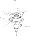
- Fig. 1 is a schematic representation of a preferred embodiment of a heat exchanger according to the present invention.
- the heat exchanger 1 comprises a shell 2, a treatment chamber 6 arranged within the shell 2, which is connected to a product inlet 7 (not shown in Fig. 1 ) in the upper region of the heat exchanger 1 and at least one product outlet 8 in the lower region of the heat exchanger 1 and has the shape of a substantially vertically oriented hollow cylinder, wherein the hollow cylinder is delimited by an inner cylinder wall 5 and by an outer cylinder wall 9.
- the heat exchanger 1 further comprises an inner cylindrical gas chamber 3 within the inner cylinder wall 5 of the treatment chamber 6, which is connected to a gas inlet 4 arranged in the lower region of the heat exchanger 1.
- the heat exchanger 1 further comprises a gas outlet 11, which is connected to an outer hollow cylindrical gas chamber 10, which in turn is arranged between the outer cylinder wall 9 of the treatment chamber 6 and the jacket 2 of the heat exchanger 1.
- the inner cylinder wall 5 and the outer cylinder wall 9 are gas-permeable, but the particles of the solid bed cannot essentially pass through the cylinder walls 5, 9.
- the heat exchanger 1 according to Fig. 1 is shown open at the top for schematic reasons. However, the heat exchanger 1 according to the invention is closed at the top and has only one product inlet 7 there.
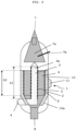
- Fig. 2 is a schematic side view of the embodiment of the heat exchanger according to Fig. 1 shown.
- Like reference numerals describe like components.
- the inner cylinder wall 5 has a height h1 which is greater than the height h2 of the outer cylinder wall 9.
- a distribution area 7a can be located between the upper product inlet 7 and the treatment chamber 6, from which the solids are fed as evenly as possible into the treatment chamber 6. To ensure this distribution, it is preferable to ensure that a sufficiently high fill level is always maintained in the distribution area 7a. This can be ensured, for example, by using a level probe 7b in the distribution chamber 7a.
- FIG. 3 a schematic representation of a preferred embodiment of a system 12 according to the present invention is shown.
- Annex 12 according to Fig. 3 has a reactor 13 for producing a polymer melt.
- This can be a reactor in which melt polymerization is carried out, thus producing a prepolymer from the monomers.
- the reactor 13 can also be a device for melting a solid product, for example, a prepolymer.
- the reactor 13 in this case can be an extruder.
- the molten material is transferred to a granulation device 14.
- granules are produced from the molten material in a known manner.
- this can be an underwater granulator. In this case, granulation takes place underwater.
- the resulting granules are simultaneously cooled in the granulator 14.
- the cooling must not be so severe that the granules are cooled below their crystallization temperature range. This can be achieved by using heated water having a temperature above 50°C, but at least 10°C below its pressure-dependent boiling point, in particular a temperature below the Tg of the polycondensate, preferably a temperature of 50 to 80°C.
- PET polyethylene terephthalate
- the granules should be cooled to a temperature of 110 to 180°C, preferably 115 to 160°C and particularly preferably 120 to 150°C.
- the granulate is transferred via a connecting line to a unit for drying the granulate (separation device) 15.
- a unit for drying the granulate (separation device) 15 For To avoid excessive cooling of the granulate, it should be discharged from the granulator 14 and through the connecting line as quickly as possible.
- the flow velocity in the connecting line can be increased by introducing a gas stream (preferably air).
- the granule drying unit (separation device) 15 the granules are separated from the liquid cooling medium (water) and dried.
- the separated cooling medium is preferably fed through a pipeline (not shown) back into a cooling medium storage container, which is connected to the granulation device 14 and from which the cooling medium can be transferred to the granulation device 14.
- the drying of the granules in the unit for drying the granules (separating device) 15 is preferably carried out in addition to a mechanical separating device with the aid of gas, preferably air or a gas atmosphere essentially comprising air, at a temperature of 100 to 200°C, preferably 110 to 160°C.
- gas preferably air or a gas atmosphere essentially comprising air
- the granulate is transferred from the separation device 15 via a connecting line (in which a rotary valve (not shown) is preferably arranged) into a crystallization unit 16.
- the granulate can pass unhindered from the separation device 15 into the unit 16.
- the unit 16 is a heat exchanger 1 according to the invention, in which case a subsequent heat exchanger 1 can usually be dispensed with.
- unit 16 the essentially amorphous granules are at least partially crystallized. Within unit 16, the granules are either without gas flow or by a countercurrent or cross-flow through unit 16.
- Unit 16 may, for example, be a rigid container or a moving trough (vibrating trough).
- Crystallization of the particles preferably occurs without external energy input.
- the crystallized granules leave unit 16 via a discharge device, for example, a shut-off unit such as a rotary valve 6a.
- a second lock unit (such as a rotary valve) can be arranged downstream of the rotary valve.
- the granulate is transferred from the crystallization unit 16 via a connecting line, usually by pneumatic conveyance, into a preheater, which is a heat exchanger 1 according to the invention.
- a buffer 19 can be arranged between the crystallization unit 16 and the heat exchanger 1 according to the invention, from which the material can be transferred in a controlled manner into the heat exchanger 1 according to the invention by means of a cell wheel valve 19a.
- a lock unit such as a rotary valve 18a can be arranged downstream of the heat exchanger 1.
- a sufficient filling level in the heat exchanger 1 is ensured either by controlling the lock unit 18a or 19a based on a measuring signal from the level probe 7b (not shown here).
- the granulate can be removed from the heat exchanger 1 via a connecting line, usually by pneumatic conveying of a further thermal treatment such as dealdehydization, drying, or SSP reaction in a reactor 18.
- a further thermal treatment such as dealdehydization, drying, or SSP reaction in a reactor 18.
- the particles can also be fed directly to a cooling stage.
- a lock unit such as a rotary valve (not shown) can be arranged downstream of the reactor 18.
- the process gas used in heat exchanger 1 is preferably conducted through a closed circuit system of pipes 17a.
- the process gas enters heat exchanger 1 through inlet opening 4 and exits heat exchanger 1 through outlet opening 11.
- a fan 17b is located in the process gas circuit system to circulate the gas.
- a further heat exchanger 17c is provided upstream of inlet opening 4 to bring the gas to the desired temperature before it enters heat exchanger 1.
- the gas is preferably heated in heat exchanger 17c.
Landscapes
- Engineering & Computer Science (AREA)
- Mechanical Engineering (AREA)
- Physics & Mathematics (AREA)
- Thermal Sciences (AREA)
- General Engineering & Computer Science (AREA)
- Processing And Handling Of Plastics And Other Materials For Molding In General (AREA)
- Heat-Exchange Devices With Radiators And Conduit Assemblies (AREA)
Claims (15)
- Échangeur de chaleur (1) pour un matériau solide en vrac, comprenant- une enveloppe (2)- une chambre de traitement (6) disposée à l'intérieur de l'enveloppe (2), qui est reliée à une entrée de produit (7) dans la partie supérieure de l'échangeur de chaleur (1) et à au moins une sortie de produit (8) dans la partie inférieure de l'échangeur de chaleur (1) et qui a la forme d'un cylindre creux sensiblement aligné verticalement, le cylindre creux étant délimité par une paroi cylindrique intérieure (5) et par une paroi cylindrique extérieure (9),- une chambre à gaz cylindrique intérieure (3) située à l'intérieur de la paroi cylindrique intérieure (5) de la chambre de traitement (6), qui est reliée à une entrée de gaz (4),- une chambre à gaz cylindrique creuse extérieure (10) située entre la paroi cylindrique extérieure (9) de la chambre de traitement (6) et l'enveloppe (2) de l'échangeur de chaleur (1), qui est reliée à une sortie de gaz (11),dans lequel la paroi intérieure du cylindre (5) et la paroi extérieure du cylindre (9) sont perméables aux gaz, mais les particules du matériau solide en vrac ne peuvent pratiquement pas passer à travers les parois du cylindre (5, 9),caractérisée en ce que la paroi cylindrique intérieure (5) a une hauteur (h1) supérieure à la hauteur (h2) de la paroi cylindrique extérieure (9).
- Échangeur de chaleur selon la revendication 1, caractérisé en ce que la hauteur (h1) de la paroi intérieure du cylindre (5) est supérieure de 1 à 50 %, de préférence de 5 à 40 %, de préférence encore de 10 à 30 % à la hauteur (h2) de la paroi extérieure du cylindre (9).
- Échangeur de chaleur selon la revendication 1 ou 2, caractérisé en ce que la paroi du cylindre intérieur (5) et la paroi du cylindre extérieur (9) sont formées d'une plaque fendue qui est formée d'une structure de support et de barres profilées disposées sur celle-ci.
- Échangeur de chaleur selon la revendication 3, caractérisé en ce que les barres profilées sont disposées sur le côté de la chambre de traitement (6) et sont espacées les unes des autres de manière à ce que les particules du matériau solide en vrac ne puissent pas essentiellement passer à travers.
- Échangeur de chaleur selon la revendication 3 ou 4, caractérisé en ce que les barres profilées de la paroi extérieure du cylindre (9) sont disposées verticalement vers la chambre de traitement (6).
- Échangeur de chaleur selon l'une des revendications 1 à 5, caractérisé en ce que la chambre à gaz extérieure (10) a une section d'extrémité conique (10a) qui est effilée vers l'extrémité inférieure de l'échangeur de chaleur (1).
- Échangeur de chaleur selon l'une des revendications 1 à 6, caractérisé en ce que la chambre à gaz intérieure (3) a une section d'extrémité conique (3a) qui est effilée vers l'extrémité supérieure de l'échangeur de chaleur.
- Procédé de traitement thermique d'un matériau solide en vrac dans un échangeur de chaleur (1) selon l'une quelconque des revendications 1 à 7, comprenant les étapes suivantes :a) Introduire la matière solide en vrac dans l'échangeur de chaleur (1) par l'entrée de produit (7) de l'échangeur de chaleur (1), de sorte que la matière solide en vrac entre dans la chambre de traitement (6) de l'échangeur de chaleur (1) et traverse l'échangeur de chaleur (1) de haut en bas jusqu'à l'au moins une sortie de produit (8) ;b) Introduire un gaz de traitement par l'entrée de gaz (4) de l'échangeur de chaleur (1) dans la chambre à gaz intérieure (3) de l'échangeur de chaleur (1), le gaz ayant une température différente de celle du matériau solide en vrac ;c) Traitement thermique du matériau solide en vrac dans la chambre de traitement (6) par écoulement de gaz depuis la chambre à gaz intérieure (3) à travers la chambre de traitement (6), le gaz s'écoulant essentiellement horizontalement depuis la chambre à gaz intérieure (3) à travers la paroi du cylindre intérieur (5), puis à travers la paroi du cylindre extérieur (9) dans la chambre à gaz extérieure (10) ;d) Évacuation du gaz de la chambre à gaz extérieure (10) par la sortie de gaz (11) de l'échangeur de chaleur.
- Procédé selon la revendication 8, caractérisé par le fait que le gaz s'écoule à travers la paroi intérieure du cylindre (5) à une vitesse superficielle comprise entre 0,3 et 0,8 m/s.
- Procédé selon la revendication 8 ou 9, caractérisé par le fait que le gaz est conduit dans un circuit (17a) de la sortie de gaz (11) à l'entrée de gaz (4).
- Procédé selon la revendication 10, caractérisé en ce que le gaz est purifié entre la sortie de gaz (11) et l'entrée de gaz (10) et soumis à un traitement thermique.
- Procédé selon l'une des revendications 8 à 11, caractérisé en ce que le matériau solide en vrac est un vrac de particules de polyéthylène téréphtalate homopolymère ou de l'un de ses copolymères.
- Procédé selon l'une des revendications 8 à 12, caractérisé en ce que, à l'étape c), la température du matériau solide en vrac est augmentée.
- Procédé selon la revendication 13, caractérisé en ce que, à l'étape c), le matériau solide en vrac est chauffé pour une étape de traitement thermique supplémentaire, de préférence pour une postcondensation en phase solide.
- Installation de production d'un polycondensat, de préférence du polyéthylène téréphtalate, comprenant un échangeur de chaleur (1) selon l'une quelconque des revendications 1 à 7, qui est de préférence disposé comme préchauffeur en amont d'un réacteur SSP (18) pour la réalisation d'une post-condensation en phase solide.
Priority Applications (3)
| Application Number | Priority Date | Filing Date | Title |
|---|---|---|---|
| EP23163005.4A EP4435366B1 (fr) | 2023-03-21 | 2023-03-21 | Echangeur de chaleur pour un lit de matière solide |
| CN202480019760.9A CN120835977A (zh) | 2023-03-21 | 2024-03-01 | 用于固态松散材料的热交换器 |
| PCT/EP2024/055320 WO2024193976A1 (fr) | 2023-03-21 | 2024-03-01 | Échangeur de chaleur pour matériau en vrac solide |
Applications Claiming Priority (1)
| Application Number | Priority Date | Filing Date | Title |
|---|---|---|---|
| EP23163005.4A EP4435366B1 (fr) | 2023-03-21 | 2023-03-21 | Echangeur de chaleur pour un lit de matière solide |
Publications (3)
| Publication Number | Publication Date |
|---|---|
| EP4435366A1 EP4435366A1 (fr) | 2024-09-25 |
| EP4435366B1 true EP4435366B1 (fr) | 2025-06-11 |
| EP4435366C0 EP4435366C0 (fr) | 2025-06-11 |
Family
ID=85724958
Family Applications (1)
| Application Number | Title | Priority Date | Filing Date |
|---|---|---|---|
| EP23163005.4A Active EP4435366B1 (fr) | 2023-03-21 | 2023-03-21 | Echangeur de chaleur pour un lit de matière solide |
Country Status (3)
| Country | Link |
|---|---|
| EP (1) | EP4435366B1 (fr) |
| CN (1) | CN120835977A (fr) |
| WO (1) | WO2024193976A1 (fr) |
Family Cites Families (9)
| Publication number | Priority date | Publication date | Assignee | Title |
|---|---|---|---|---|
| DE481282C (de) * | 1926-09-07 | 1929-08-17 | Otto Nordstroem | Schachttrockner |
| CA1201263A (fr) * | 1983-04-05 | 1986-03-04 | Cactus Machinery Inc. | Dispositif de conditionnement des plastiques hygroscopiques |
| US5145742A (en) | 1990-08-03 | 1992-09-08 | Eastman Kodak Company | Polymer pellet configuration for solid-state polymerization |
| DE4300913A1 (de) | 1993-01-15 | 1994-07-21 | Buehler Gmbh | Dächertrockner |
| DE19743461A1 (de) | 1997-10-01 | 1999-04-08 | Buehler Ag | Trockner-Wärmetauscher |
| DE19840358A1 (de) * | 1998-09-04 | 2000-03-09 | Motan Holding Gmbh | Verfahren zum Heizen und/oder Trocknen von fließfähigem Schüttgut, vorzugsweise von Kunststoffgranulat, und Heizeinrichtung zur Durchführung des Verfahrens |
| DE10144747A1 (de) | 2001-09-11 | 2003-03-27 | Buehler Ag | Kontinuierliche thermische Behandlung von Schüttgütern |
| DE102006058510A1 (de) | 2006-12-12 | 2008-06-19 | Bühler AG | Verfahren und Vorrichtung zur Herstellung und Behandlung von Granulatkörnern |
| EP3650186B1 (fr) | 2018-11-08 | 2023-07-19 | Polymetrix AG | Procédé et dispositif de cristallisation directe de polycondensats |
-
2023
- 2023-03-21 EP EP23163005.4A patent/EP4435366B1/fr active Active
-
2024
- 2024-03-01 WO PCT/EP2024/055320 patent/WO2024193976A1/fr not_active Ceased
- 2024-03-01 CN CN202480019760.9A patent/CN120835977A/zh active Pending
Also Published As
| Publication number | Publication date |
|---|---|
| WO2024193976A1 (fr) | 2024-09-26 |
| CN120835977A (zh) | 2025-10-24 |
| EP4435366A1 (fr) | 2024-09-25 |
| EP4435366C0 (fr) | 2025-06-11 |
Similar Documents
| Publication | Publication Date | Title |
|---|---|---|
| EP2712881B1 (fr) | Procédé et dispositif de cristallisation directe de polymères sous gaz inerte | |
| DE69631305T2 (de) | Verfahren zur Herstellung von Polymilchsäure | |
| US11566104B2 (en) | Process and apparatus for direct crystallization of polycondensates | |
| EP2101972B1 (fr) | Procédé de production de granulés de polycondensat cristallisés homogènes | |
| DE1905677A1 (de) | Verfahren zum Kristallisieren von Polyestern | |
| EP3650186B1 (fr) | Procédé et dispositif de cristallisation directe de polycondensats | |
| EP3363841B1 (fr) | Procédé et dispositif de cristallisation directe de polycondensats | |
| WO2009062321A1 (fr) | Procédé pour cristalliser des polymères cristallisables présentant une tendance à l'adhésion élevée | |
| DE102006027176B4 (de) | Verfahren und Vorrichtung zur Verringerung des Acetaldehydgehaltes von Polyestergranulat sowie Polyestergranulat | |
| EP3865529B1 (fr) | Procédé et dispositif de traitement d'un mélange d'une matière polyester recyclée et d'un prépolymère polyester provenant d'un procédé de fabrication de polyester | |
| DE102009009957A1 (de) | Verfahren zur Herstellung von Polyesterpartikeln bei hohem Durchsatz in einer Linie | |
| DE2557580A1 (de) | Verfahren und vorrichtung zur herstellung von polykondensaten | |
| DE102006012587A1 (de) | Verfahren und Vorrichtung zur Kristallisation von Polyestermaterial | |
| EP2671902B1 (fr) | Conditionnement de polyamide | |
| EP4435366B1 (fr) | Echangeur de chaleur pour un lit de matière solide | |
| DE102015206688B4 (de) | Verfahren zur Kristallisation und Abtrennung niedermolekularer Komponenten aus einem Granulat eines kristallisationsfähigen thermoplastischen Materials sowie Vorrichtung hierzu | |
| DE102005016146A1 (de) | Herstellung eines hochmolekularen Polykondensates | |
| EP2043831B1 (fr) | Procédé de cristallisation d'un polymère cristallisant lentement et granulés polymères | |
| EP4180199B1 (fr) | Procédé et dispositif de fabrication et de traitement d'un mélange de matière de polyester recyclé et d'un prépolymère de polyester à partir d'un processus de fabrication de polyester | |
| DE10259694A1 (de) | Herstellung eines Polyester-Performs mit reduziertem Acetaldehydgehalt | |
| EP3689440A1 (fr) | Procédé et dispositif de nettoyage de gaz de processus mis en circulation provenant des traitements des matériaux granulés | |
| DE102007026737A1 (de) | Verfahren zur Kristallisation eines langsam kristallisierenden Polymeren |
Legal Events
| Date | Code | Title | Description |
|---|---|---|---|
| PUAI | Public reference made under article 153(3) epc to a published international application that has entered the european phase |
Free format text: ORIGINAL CODE: 0009012 |
|
| STAA | Information on the status of an ep patent application or granted ep patent |
Free format text: STATUS: THE APPLICATION HAS BEEN PUBLISHED |
|
| AK | Designated contracting states |
Kind code of ref document: A1 Designated state(s): AL AT BE BG CH CY CZ DE DK EE ES FI FR GB GR HR HU IE IS IT LI LT LU LV MC ME MK MT NL NO PL PT RO RS SE SI SK SM TR |
|
| STAA | Information on the status of an ep patent application or granted ep patent |
Free format text: STATUS: REQUEST FOR EXAMINATION WAS MADE |
|
| GRAP | Despatch of communication of intention to grant a patent |
Free format text: ORIGINAL CODE: EPIDOSNIGR1 |
|
| STAA | Information on the status of an ep patent application or granted ep patent |
Free format text: STATUS: GRANT OF PATENT IS INTENDED |
|
| 17P | Request for examination filed |
Effective date: 20250109 |
|
| RIC1 | Information provided on ipc code assigned before grant |
Ipc: F26B 17/00 20060101AFI20250117BHEP |
|
| INTG | Intention to grant announced |
Effective date: 20250203 |
|
| GRAS | Grant fee paid |
Free format text: ORIGINAL CODE: EPIDOSNIGR3 |
|
| GRAA | (expected) grant |
Free format text: ORIGINAL CODE: 0009210 |
|
| STAA | Information on the status of an ep patent application or granted ep patent |
Free format text: STATUS: THE PATENT HAS BEEN GRANTED |
|
| AK | Designated contracting states |
Kind code of ref document: B1 Designated state(s): AL AT BE BG CH CY CZ DE DK EE ES FI FR GB GR HR HU IE IS IT LI LT LU LV MC ME MK MT NL NO PL PT RO RS SE SI SK SM TR |
|
| REG | Reference to a national code |
Ref country code: GB Ref legal event code: FG4D Free format text: NOT ENGLISH |
|
| REG | Reference to a national code |
Ref country code: CH Ref legal event code: EP |
|
| REG | Reference to a national code |
Ref country code: IE Ref legal event code: FG4D Free format text: LANGUAGE OF EP DOCUMENT: GERMAN |
|
| REG | Reference to a national code |
Ref country code: DE Ref legal event code: R096 Ref document number: 502023001115 Country of ref document: DE |
|
| U01 | Request for unitary effect filed |
Effective date: 20250707 |
|
| U07 | Unitary effect registered |
Designated state(s): AT BE BG DE DK EE FI FR IT LT LU LV MT NL PT RO SE SI Effective date: 20250711 |
|
| PG25 | Lapsed in a contracting state [announced via postgrant information from national office to epo] |
Ref country code: ES Free format text: LAPSE BECAUSE OF FAILURE TO SUBMIT A TRANSLATION OF THE DESCRIPTION OR TO PAY THE FEE WITHIN THE PRESCRIBED TIME-LIMIT Effective date: 20250611 |
|
| PG25 | Lapsed in a contracting state [announced via postgrant information from national office to epo] |
Ref country code: GR Free format text: LAPSE BECAUSE OF FAILURE TO SUBMIT A TRANSLATION OF THE DESCRIPTION OR TO PAY THE FEE WITHIN THE PRESCRIBED TIME-LIMIT Effective date: 20250912 Ref country code: NO Free format text: LAPSE BECAUSE OF FAILURE TO SUBMIT A TRANSLATION OF THE DESCRIPTION OR TO PAY THE FEE WITHIN THE PRESCRIBED TIME-LIMIT Effective date: 20250911 |
|
| PG25 | Lapsed in a contracting state [announced via postgrant information from national office to epo] |
Ref country code: HR Free format text: LAPSE BECAUSE OF FAILURE TO SUBMIT A TRANSLATION OF THE DESCRIPTION OR TO PAY THE FEE WITHIN THE PRESCRIBED TIME-LIMIT Effective date: 20250611 |
|
| PG25 | Lapsed in a contracting state [announced via postgrant information from national office to epo] |
Ref country code: RS Free format text: LAPSE BECAUSE OF FAILURE TO SUBMIT A TRANSLATION OF THE DESCRIPTION OR TO PAY THE FEE WITHIN THE PRESCRIBED TIME-LIMIT Effective date: 20250911 |
|
| PG25 | Lapsed in a contracting state [announced via postgrant information from national office to epo] |
Ref country code: IS Free format text: LAPSE BECAUSE OF FAILURE TO SUBMIT A TRANSLATION OF THE DESCRIPTION OR TO PAY THE FEE WITHIN THE PRESCRIBED TIME-LIMIT Effective date: 20251011 |
|
| PG25 | Lapsed in a contracting state [announced via postgrant information from national office to epo] |
Ref country code: SM Free format text: LAPSE BECAUSE OF FAILURE TO SUBMIT A TRANSLATION OF THE DESCRIPTION OR TO PAY THE FEE WITHIN THE PRESCRIBED TIME-LIMIT Effective date: 20250611 |
|
| PG25 | Lapsed in a contracting state [announced via postgrant information from national office to epo] |
Ref country code: CZ Free format text: LAPSE BECAUSE OF FAILURE TO SUBMIT A TRANSLATION OF THE DESCRIPTION OR TO PAY THE FEE WITHIN THE PRESCRIBED TIME-LIMIT Effective date: 20250611 |
|
| PG25 | Lapsed in a contracting state [announced via postgrant information from national office to epo] |
Ref country code: PL Free format text: LAPSE BECAUSE OF FAILURE TO SUBMIT A TRANSLATION OF THE DESCRIPTION OR TO PAY THE FEE WITHIN THE PRESCRIBED TIME-LIMIT Effective date: 20250611 |
|
| PG25 | Lapsed in a contracting state [announced via postgrant information from national office to epo] |
Ref country code: SK Free format text: LAPSE BECAUSE OF FAILURE TO SUBMIT A TRANSLATION OF THE DESCRIPTION OR TO PAY THE FEE WITHIN THE PRESCRIBED TIME-LIMIT Effective date: 20250611 |