EP4433404B1 - Auswahl der fahrtrichtung einer aufzugskabine - Google Patents
Auswahl der fahrtrichtung einer aufzugskabine Download PDFInfo
- Publication number
- EP4433404B1 EP4433404B1 EP21815948.1A EP21815948A EP4433404B1 EP 4433404 B1 EP4433404 B1 EP 4433404B1 EP 21815948 A EP21815948 A EP 21815948A EP 4433404 B1 EP4433404 B1 EP 4433404B1
- Authority
- EP
- European Patent Office
- Prior art keywords
- elevator car
- estimate
- travel
- estimated position
- amount
- Prior art date
- Legal status (The legal status is an assumption and is not a legal conclusion. Google has not performed a legal analysis and makes no representation as to the accuracy of the status listed.)
- Active
Links
Images


Classifications
-
- B—PERFORMING OPERATIONS; TRANSPORTING
- B66—HOISTING; LIFTING; HAULING
- B66B—ELEVATORS; ESCALATORS OR MOVING WALKWAYS
- B66B5/00—Applications of checking, fault-correcting, or safety devices in elevators
- B66B5/02—Applications of checking, fault-correcting, or safety devices in elevators responsive to abnormal operating conditions
- B66B5/027—Applications of checking, fault-correcting, or safety devices in elevators responsive to abnormal operating conditions to permit passengers to leave an elevator car in case of failure, e.g. moving the car to a reference floor or unlocking the door
Definitions
- the invention concerns in general the technical field of conveyor systems. More particularly, the invention concerns elevator systems.
- Elevator service gets interrupted due to a failure in a power supply to an elevator system.
- an elevator car with passengers gets stuck between two floors and the situation needs to be solved somehow especially if the failure in the power supply continues a long period of time.
- the elevator system may be equipped with energy storages, such as batteries, configured to store an amount of energy allowing a transport of the elevator car to a floor under so-called rescue drive operation.
- energy storages such as batteries
- the size of the energy storage is optimized, and the goal is to apply as small energy storages as possible to minimize their size and cost as well as to minimize their effect in overall design of the elevator system.
- An object of the invention is to present a method, an apparatus, an elevator system, and a computer program for selecting a travel direction of an elevator car.
- a method for selecting a travel direction of an elevator car for a rescue drive comprises:
- the amount of energy required to cause a movement of the first reference distance or a movement of the second reference distance may be derived from data indicative of an input current of an electric motor configured to cause the respective movement.
- the estimated position of the elevator car may be determined based on at least one of the following: data indicative of a position of the elevator car obtained from at least one sensor; position data of the elevator car stored in data storage.
- the estimated position of the elevator car may be determined from the position data stored in the data storage by selecting the piece of data as the data for the estimated position which is stored to the data storage most recently prior to an event that caused the rescue drive.
- the estimating of the amount of energy required to move the elevator car from its estimated position to the next landing in the first direction or to the next landing in the opposite direction to the first direction may be performed by estimating an amount of energy needed to generate a torque to the traction sheave to move the elevator car to respective directions.
- the step of estimating the amount of energy required to move the elevator car from its estimated position to the next landing in the first direction or in the opposite direction to the first direction may comprise a determination of information indicative a change in balance of the elevator system over a first path from the estimated position of the elevator car to the next landing in the first direction and over a second path from the estimated position of the elevator car to the next landing in the opposite direction to the first direction.
- the method may further comprise:
- the method may further comprise:
- the selection of the travel direction may comprise a generation of a control signal to an elevator drive to cause a generation of a control signal to the electric motor.
- an apparatus for selecting a travel direction of an elevator car for a rescue drive is provided, the apparatus is configured to execute the method according to the first aspect as defined above.
- an elevator system comprising an apparatus according to the second aspect as defined above.
- a computer program comprising instructions to cause the apparatus according to the second aspect as defined above to carry out the method according to the first aspect as defined above.
- a number of refers herein to any positive integer starting from one, e.g. to one, two, or three.
- a plurality of refers herein to any positive integer starting from two, e.g. to two, three, or four.
- FIG. 1 illustrates schematically an elevator system 1000 according to an example embodiment into which a functionality according to the present invention may implemented to.
- the elevator system 1000 as disclosed in Figure 1 may comprise an elevator car 110 arranged to be moved or movable in an elevator shaft 120 e.g. along guide rails mounted in the elevator shaft 120.
- the moving of the elevator car 110 may be implemented by a hoisting rope or belt 130 in connection with a counterweight 140 over a traction sheave 150 or the like.
- the operation of the elevator system 1000 may be achieved by controlling a rotation of the traction sheave 150 with an electric motor 160 and elevator brakes 170.
- the electric motor 160 may be controlled with a frequency converter 180 configured to provide an input current to the electric motor 160 to cause the electric motor 160 to operate in a controlled manner.
- An overall controlling of the elevator system may be performed by an apparatus 200 corresponding e.g. to an elevator controller which, among other functionalities, receives a feedback from other elevator entities, such as from call giving devices and so on, so as to generate the control signals to the frequency converter 180 in accordance with the feedback.
- an apparatus 200 corresponding e.g. to an elevator controller which, among other functionalities, receives a feedback from other elevator entities, such as from call giving devices and so on, so as to generate the control signals to the frequency converter 180 in accordance with the feedback.
- the elevator system may also comprise a number of sensors 190 residing in the elevator shaft 120 and/or in elevator car 110, for example.
- the sensors 190 may be of any type suitable for generating measurement data from which it is possible to derive an estimation of a position of the elevator car 110 in the elevator shaft 120.
- the estimation of the position shall be understood in a broad manner, and it may mean either an exact position or some inaccurate estimation of the position for the purpose of the present invention as is discussed in the forthcoming description.
- the sensors 190 applicable for generating the measurement data indicative of the position of the elevator car 110 may be contact sensors mounted in the shaft configured to interact mechanically, electrically, magnetically, or optically with a counterpart residing in the elevator car 110 in response to that the elevator car 110 passes by the respective sensors 190.
- the number of sensors 190 may be mounted to the hoisting machine system, such as to the electric motor 160.
- measurement data may be obtained from the motor encoder based on which the estimate on the position may be determined.
- a non-limiting example of a sensor 190 associated to the elevator car 110 may be a barometer providing measurement data indicative of a pressure experienced in varied locations in the elevator shaft 120 from which it is possible to generate the estimate. Any other sensor type may also be applied in the context of the present invention for obtaining measurement data indicative, either directly or indirectly, of the position of the elevator car 110.
- the elevator system 1000 is supplied with power from mains current in normal operation situations.
- the elevator system in accordance with the present invention may be equipped with an energy storage 195 which may be arranged to supply power to the elevator system 1000, or at least to at least some entities of it, in special situations, such as in an emergency situation.
- the energy storage 195 suitable to store electrical energy may e.g. be a battery implemented in any known manner.
- the supply of the energy source 195 may be arranged so that the supply of the electrical energy may be automatically initiated in response to a detection that the power supply from the mains fails or the supply may be arranged by implementing a predefined functionality to the energy storage, or to the elevator system, so as to enable the supply of energy at a predefined event.
- the supply of the electrical energy may be arranged to a power network of the elevator system, or only to critical entities of the elevator system in order to perform a method as is described in the forthcoming description.
- the power supply is arranged through the frequency converter 180 so that at least the frequency converter 180 and the electric motor 160 are energized.
- the elevator system 1000 comprises an apparatus 200 configured to perform at least part of a control operations of the elevator system 1000 wherein the apparatus 200 may refer to an elevator controller.
- the apparatus 200 is communicatively connected to at least some entities of the elevator system 1000 so as to deliver control signals thereto and receive data from the elevator system 1000, such as the sensor data.
- the apparatus 200 is at least configured to control an operation of the elevator drive system comprising at least both the frequency converter 180 and the electric motor 160.
- the apparatus 200 is also arranged to receive power from the energy storage 195 in case of a power failure from the mains.
- the apparatus 200 and the frequency converter 180 are described and illustrated in Figure 1 as separate entities and devices, their functionalities may also be integrated into a single device if seen convenient from an implementation point of view.
- the elevator system is arranged to travel between a plurality of landings 10, or floors, so as to transport passengers and any other load between the landings 10 served by the elevator system 1000.
- An energy consumption of the elevator system 1000 during a ride is also dependent on so-called balancing of the elevator system 1000 in question.
- the balancing refers to a selection of an elevator car 110 and the respective counterweight 140 as well as the effect of the weight of the rope 130 on both sides divided by the traction sheave 150.
- the elevator system 1000 may be in balance at some position of the elevator car 110 in the elevator shaft 120 i.e. when the weights on both sides with respect to the traction sheave 150 are equal i.e. the elevator car 110 does not move even if elevator brakes are inactivated.
- the balancing situation may be overbalanced or underbalanced at some other position of the elevator car 110 in the elevator shaft 120 due to the different portion of the rope 130 on each side divided by the traction sheave 150.
- the overbalanced situation refers to that the elevator car 110 travels downwards if it is allowed to move freely and in the underbalanced situation the elevator car 110 travels upwards.
- the elevator system 1000 may be designed so that the system is in balance only at one end of the travel path in the elevator shaft 120, or even so that there is no position in which the elevator system 1000 is in balance.
- the balancing situation may be manipulated with so-called compensation ropes mounted below the elevator car 110 and the counterweight, respectively.
- an effect of a weight of an elevator travelling cable may be taken into account in the consideration of the balancing together with the above mentioned other items, i.e. the elevator car 130, the counterweigh 140, the elevator rope 130, and the compensation ropes if any.
- the present invention provides a solution for selecting an optimal direction for a rescue drive in case the operation of the elevator system 1000 is halted due to a power failure.
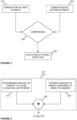
- a method according to an example embodiment is schematically illustrated in Figure 2 wherein the method provides a solution for selecting a travel direction of an elevator car 110 for a rescue drive, or similar.
- the method may be performed by a computing unit, such as a controller, as is described in the forthcoming description.
- the entity configured to perform at least part of the method may be the apparatus 200 configured to perform at least part of the control operations of the elevator system 1000.
- the method may be initiated by generating a first estimate 210 indicative of a total energy consumption of causing the elevator car 110 to travel from its estimated position to a next landing in a first direction and by generating a second estimate 220 indicative of a total energy consumption of causing the elevator car 110 to travel from its estimated position to a next landing in an opposite direction to the first direction.
- the apparatus 200 may determine, based on any applicable data it has access to, an estimated position of the elevator car 110 in the elevator shaft 120 where the elevator car 110 has stopped due to a specific situation, such as due to a power failure.
- the apparatus 200 may be configured to generate a first estimate 210 indicative of a total energy consumption of causing the elevator car 110 to travel from its estimated position to a next landing in a first direction. Further, the apparatus 200 is configured to generate the second estimate indicative of a total energy consumption of causing the elevator car 110 to travel from its estimated position to a next landing in the opposite direction to the first direction. In other words, the apparatus 200 is configured to generate the first and the second estimation by utilizing the information on the estimated position of the elevator car 110 at least in part.
- the term total energy consumption in the context of the estimations shall be understood to cover a selected number of sources included in the generation of the total energy consumption as is described in the forthcoming description.
- first direction and the second direction opposite to the first direction in the context of the elevator system 1000 substantially refer to vertical directions the elevator car 110 is arranged to travel in the elevator shaft 120.
- first direction may be vertically upwards whereas the second direction may then be vertically downwards, or vice versa.
- the generations of the first estimate and the second estimate 210, 220 may be performed concurrently at least in part or subsequently to each other.
- the apparatus 200 is configured to compare 230 the first estimate and the second estimate together.
- the aim of the comparison 230 is to determine the travel direction to the elevator car 110 to the next landing wherein an energy consumption of the travel is minimized.
- the comparison step 230 may be implemented so that the first estimation and the second estimation is compared together and the information on the one being smaller is obtained.
- the apparatus 200 In response to the comparison 230 the apparatus 200 is arranged to select 240 the travel direction for the rescue drive corresponding to an estimate being smaller among the first estimate and the second estimate. Hence, the apparatus 200 maintains the information linking the total energy consumption to each of the direction and the respective travel direction and generates as an output of the selection step 240 data indicative of the travel direction.
- the apparatus 200 may be configured to generate a control signal to power generation means, such as to a frequency converter 180 so as to control an electric motor of the elevator system 1000, to cause a travel of the elevator car 110 to the selected travel direction in the elevator shaft 120.
- the total energy consumption may consists of at least two aspects.
- an amount of energy required to cause the elevator car 110 to move to a selected direction is determined 310 and the determination is performed by controlling the elevator car 110 to move a reference distance to the selected direction.
- a second aspect related to the total energy consumption in accordance with the example embodiment is that an amount of energy required to move the elevator car 110 from its estimated position to the next landing in the selected direction is estimated 320.
- the apparatus 200 may be configured to generate a control signal to the power generation means to instruct the power generation means to generate a force to move the elevator car 110 the reference distance to the selected direction wherein the selected direction may first be the first direction or the second direction.
- the apparatus 200 may be configured to generate another control signal to the power generation means to instruct the power generation means to generate a force to move the elevator car 110 another reference distance to the second direction opposite to the first direction.
- the movement of a reference distance to the second direction may be initiated from the position the elevator car 110 resides after the movement of a reference distance to the first direction, or the elevator car 110 may be returned to the starting position, or a reference position, i.e. to the position from where the movement to the first direction was initiated, before the movement to the second direction is instructed.
- the selection of the starting point for the second direction is taken into account in the estimation of the energy consumption in the manner as described in the forthcoming description.
- the elevator car 110 is caused to travel to both directions opposite to each other reference distances defined for the travel directions.
- the reference distance in the first direction and in the second direction may be the same or differ from each other.
- At least one aim of the movement of the elevator car 110 to the first direction and to the second direction is to determine how much energy is required to initiate the travel to the respective directions.
- the reference distance may be some centimeters which allows a determination of the required energy e.g. by deriving it from data indicative of an input current of an electric motor configured to cause the force for the respective movement.
- the derivation of the input current of the electric motor may be based on measurements of one or more signal values indicative of current and/or voltage applied in the elevator drive system. In other words, commonly known equations may be applied to the determination of the required energy.
- an estimation is made 320 on an amount of energy required to move the elevator car 110 from its estimated position to the next landing.
- Such an estimation is performed both to the first direction and to the second direction, separately.
- the estimations may be performed mathematically e.g. based on the estimated position of the elevator car 110 and its travel distance to the next landing in the first direction and in the second direction.
- at least some parameters of the power generation means such as input current and the duration of provision the input current to reach the respective landings may be applied to.
- the estimations may be based on information obtained from a travel history of the elevator car 110 e.g. so that a corresponding section from the travel path of the elevator car 110 is determined and the energy consumption used for the respective section, or sections, are determined and obtained so as to receive the estimations of the amount of energy required to cause the elevator car 110 to move to the respective landings.
- the apparatus 200 may be arranged to sum up 330 the amount of energy required to cause the elevator car to move to the selected direction and the amount of energy required to move the elevator car 110 from its estimated position to the next landing in the same selected direction for generating the respective estimate.
- the sum up 330 is performed separately to the determined terms in the steps 310 and 320 with respect to the first direction and to the second direction.
- the apparatus 200 may be configured to associate the terms with respect to the travel directions so that the amount of energy required to cause the elevator car 110 to travel in a direction is summed up 330 with the estimation of an amount of energy required to travel to the next landing in the same direction so as to generate the first estimate and the second estimate for the comparison 230.
- the determination of the estimated amount of energy required to move the elevator car 110 to the landing in question is performed by taking into account information indicative of a balance of the elevator system 1000 at the position the elevator car 110 resides. Further, preferable the information of the balance of the elevator system 1000 is taken into account over the travel to the respective distances. This may be advantageous since the balance changes during the travel since the mutual positions of the elevator car 110 and the counterweight 140 change during the run. This is due to that the weight of the hoisting rope 130 on both sides of the traction sheave 150 changes as the length of the rope 130 varies in the respective sides. In other words, the balance may vary during the travel which, in turn, may have effect on the required energy to move the elevator car 110 to the respective landings.
- the information on the balance may, in accordance with an embodiment, be taken into account in the evaluation of the required energy to cause the elevator car 110 to move from its estimated position to the next landing in the first direction or in the second direction by estimating mathematically an energy needed to generate a cumulative torque of a traction sheave 150 of the elevator over the distance from the position of the elevator car 110 to the landings in both directions.
- the cumulative torque may be mathematically estimated by obtaining a load information of the elevator car 110 (e.g.
- the energy needed to generate the cumulative torque may e.g. be derived from an input current needed to be supplied to the electric motor 160 to generate the cumulative torque to the traction sheave 150 as estimated.
- the same may be evaluated based on control signals generatable by the drive system, such as the frequency converter 180.
- the estimation of the amount of energy required to move the elevator car to the respective landing is based on an estimated position of the elevator car 110 in the elevator shaft 120.
- the estimation of the position i.e. the estimated position, may refer to an exact position of the elevator car 110 or to an estimation of the position with an acceptable accuracy, such as at least a knowledge of the landings between which the elevator car 110 resides.
- the estimated position of the elevator car 110 may be obtained from a sensor configured to generate data indicative of the position of the elevator car 110 or from data storage configured to store position data of the elevator car 110. In the former case, the sensor may be provided with power from energy storage even during the power failure from the mains in order to receive data indicative of the position of the elevator car 110.
- a processing entity of the apparatus 200 may be configured to determine the estimated position of the elevator car 110 from position data stored in the data storage. The determination may be performed by selecting the piece of data as the data for the estimated position which is stored to the data storage most recently prior to an event that caused the rescue drive. Such an approach is based on an arrangement that in response to the power failure an input of data to the data storage is canceled and only the data stored prior to the power failure, or a similar event, may be found from the data storage and the last stored piece of data may be identified.
- the stored data may origin from one or more sensors suitable of generating data indicative of the position of the elevator car 110, or may store data obtained from the electric motor, such as from an encoder therefrom, based on which data the position of the elevator car 110 may be determined.
- the data may e.g. be indicative of the position, a speed, or an acceleration of the elevator car prior to the unexpected stop.
- a determination of the position of the elevator car 110 may take into account other data stored in data storage, and accessible therefrom, such as information on a deceleration of the elevator car 110 when the elevator car 110 is instructed to stop due to the specific situation e.g. by applying an emergency stop mechanism.
- the travel distance over the deceleration may be determined and added to the latest known position to generate the estimation of the position.
- Further aspects, such as the load of the elevator car 110 may also be taken into account for determining the travel distance during the deceleration before the stop.
- the estimation of the position of the elevator car 110 may also comprise a step in which an accuracy of the estimation in an implementation in which there is only information available on a landing the elevator car 110 passed by at the last time before the stop is improved by evaluating a time after the detection of the bypass of the landing and based on that an estimation is made how long the elevator car 110 may have traveled during the determined time to the travel direction before the stop.
- an estimation of the position of the elevator car 110 may be generated. All in all, the estimation of the position with a predefined accuracy may provide needed information to determine a travel distance to a next landing in a first direction and another travel distance to a next landing to a second direction being opposite to the first direction. Hence, in addition to the estimation of the position of the elevator car 110 the apparatus 200 have access to data defining positions of the landings in a manner that travel distances may be determined in any of the manners as described.
- an embodiment of the invention may comprise a further step of determining an amount of energy available from an energy source 195 for the rescue drive, and then determining if the amount of energy available from the energy source 195 exceeds the estimate indicative of the total energy consumption corresponding to the selected travel direction.
- a further aspect to determine, prior to an initiation of the rescue drive may be that the energy storage is capable of providing a peak power occurring at start when the movement is initiated and/or at the end of the drive when braking the elevator car 110 to stop at the landing. This may e.g. be determined so that it is confirmed that the energy storage is capable of providing necessary current level to initiate the travel as well as to allow the braking to establish the required peak power. More specifically, this approach may be implemented so that the apparatus 200 configured to perform the method is configured to determine a first peak power required by elevator car 110 to travel from its estimated position to the next landing in the first direction and to determine a second peak power required by elevator car 110 to travel from its estimated position to the next landing in the opposite direction to the first direction.
- the determinations of the peak powers may be performed so that required peak powers for initiating the travel to the respective directions are determined with the movements of the elevator car controlled for determining the first and the second estimates of the total energy consumption as already described.
- the remaining part of the required power may be estimated mathematically by taking into account the travel distance to the respective floors (e.g. evaluating that the required power is liner over the travel distance) and estimating the required power to perform the braking e.g. based on history data or similar. By summing up these items the required peak powers to both directions may be estimated and determined.
- each of them may be compared to a reference value.
- the reference value may be dependent on one or more characteristics of the energy source, i.e.
- the information on the reference value may be stored in a memory accessible to the apparatus in order to obtain the reference value for the comparison.
- the travel direction selected based on the comparison of the first estimate and the second estimate of the total energy consumption for the rescue drive may be confirmed upon a detection that a determined peak power to a same travel direction as the selected travel direction is below the reference value. In other words, if the required peak power may be provided the selection of the travel direction based on the estimates of the total energy consumption of the elevator car may be confirmed.
- the travel direction in question may be prevented.
- the travel direction is prevented since the energy source cannot provide the necessary power throughout the travel even if it stores enough energy to the respective travel.
- the other direction is possible in terms of power and energy consumption in order to allow the travel to that direction.
- the estimation of the peak powers and the conclusions based on the estimation as described herein may be performed at least partly concurrently to the evaluation of the total energy consumption.
- at least one of the travel directions may be prevented based on the peak power estimation prior to that the selection of the travel direction based on the total energy consumption is concluded.
- the selection of the travel direction may, in some embodiments, also comprise a generation of a control signal to an elevator drive to cause a generation of a control signal to the electric motor to initiate the rescue drive.
- next landings in the first and the second direction do not necessarily refer to the next physical landings, but the ones defined to be used for rescue operations. Hence, the determinations of the total energy consumption are performed with respect to those next landings.
- FIG. 4 An example of an apparatus 200 configurable to perform the method as described is schematically illustrated in Figure 4 .
- the apparatus 200 comprises a processor 410 and a memory 420.
- the memory 420 may store data, such pieces of data as described but also computer program code 425 causing the safety operation in the described manner.
- the apparatus 200 may further comprise a communication interface 430, such as a wireless communication interface or a communication interface for wired communication, or both.
- the communication interface 430 may thus comprise one or more modems, antennas, and any other hardware and software for enabling an execution of the communication e.g. under control of the processor 410.
- I/O (input/output) components may be arranged, together with the processor 410 and a portion of the computer program code 425, to provide a user interface for receiving input from a user, such as from a technician, and/or providing output to the user of the apparatus when necessary.
- the user I/O components may include user input means, such as one or more keys or buttons, a keyboard, a touchscreen, or a touchpad, etc.
- the user I/O components may include output means, such as a loudspeaker, a display, or a touchscreen.
- the components of the apparatus may be communicatively connected to each other via data bus that enables transfer of data and control information between the components.
- the memory 420 and a portion of the computer program code 425 stored therein may further be arranged, with the processor 410, to cause the apparatus 200 to perform at least a portion of a method for selecting the travel direction as is described herein.
- the processor 410 may be configured to read from and write to the memory 420.
- the processor 410 is depicted as a respective single component, it may be implemented as respective one or more separate processing components.
- the memory 420 is depicted as a respective single component, it may be implemented as respective one or more separate components, some, or all of which may be integrated/removable and/or may provide permanent / semi-permanent / dynamic / cached storage.
- the computer program code 425 may comprise computer-executable instructions that implement functions that correspond to steps of the method when the computer program code 425 is loaded into the processor 410 of the controller 210 and executed therein.
- the computer program code 425 may include a computer program consisting of one or more sequences of one or more instructions.
- the processor 410 is able to load and execute the computer program by reading the one or more sequences of one or more instructions included therein from the memory 420.
- the one or more sequences of one or more instructions may be configured to, when executed by the processor 410, cause the apparatus 200 to perform a method as explicitly described in the description herein.
- the apparatus may comprise at least one processor 410 and at least one memory 420 including the computer program code 425 for one or more programs, the at least one memory 420 and the computer program code 425 configured to, with the at least one processor 410, cause the apparatus to perform the method.
- the computer program code 425 may be provided e.g. a computer program product comprising at least one computer-readable non-transitory medium having the computer program code 425 stored thereon, which computer program code 425, when executed by the processor 410 causes the apparatus to perform the method.
- the computer-readable non-transitory medium may comprise a memory device or a record medium such as a CD-ROM, a DVD, a Blu-ray disc, or another article of manufacture that tangibly embodies the computer program.
- the computer program may be provided as a signal configured to reliably transfer the computer program.
- the computer program code 425 may comprise a proprietary application, such as computer program code for causing an execution of the method in the manner as described in the description herein.
- the entity performing the method may also be implemented with a plurality of apparatuses, such as the one schematically illustrated in Figure 4 , as a distributed computing environment.
- one of the apparatuses may be communicatively connected with other apparatuses, and e.g. share the data of the method, to cause another apparatus to perform at least one portion of the method.
- the method performed in the distributed computing environment allows the rescue operation in the elevator system 1000 in the manner as described.
- the apparatus 200 may be a predefined controller of the elevator system 1000, such as the main controller configured to control the overall operation of the elevator system 1000.
- the apparatus 200, or the plurality of apparatuses 200 are advantageously arranged to be supplied with power from the energy storage 195 automatically in response to a power failure from the mains, or it may be provided with their own energy storage in order to confirm that the apparatus 200 is operable at any event, and capable of performing the method as described.
Landscapes
- Maintenance And Inspection Apparatuses For Elevators (AREA)
Claims (12)
- Verfahren zum Auswählen einer Fahrtrichtung einer Aufzugskabine (110) für eine Rettungsfahrt, dadurch gekennzeichnet, dass das Verfahren Folgendes umfasst:
Erzeugen (210) einer ersten Schätzung, die einen Gesamtenergieverbrauch der Aufzugskabine (110) angibt, um von ihrer geschätzten Position zu einem nächsten Flur (10) in einer ersten Richtung zu fahren, durch:Bestimmen einer Energiemenge, die erforderlich ist, um zu bewirken, dass sich die Aufzugskabine (110) durch Steuern der Aufzugskabine (110) um eine erste Referenzdistanz zu der ersten Richtung in die erste Richtung bewegt,Schätzen einer Energiemenge, die erforderlich ist, um die Aufzugskabine (110) von ihrer geschätzten Position zum nächsten Flur in der ersten Richtung zu bewegen,Summieren der Energiemenge, die erforderlich ist, um zu bewirken, dass sich die Aufzugskabine (110) in die erste Richtung bewegt, und der Energiemenge, die erforderlich ist, um die Aufzugskabine (110) von ihrer geschätzten Position zum nächsten Flur (10) in die erste Richtung zu bewegen, zum Erzeugen der ersten Schätzung,Erzeugen (220) einer zweiten Schätzung, die einen Gesamtenergieverbrauch der Aufzugskabine (110) angibt, um von ihrer geschätzten Position zu einem nächsten Flur (10) in einer zu der ersten Richtung entgegengesetzten Richtung zu fahren, durch:Bestimmen einer Energiemenge, die erforderlich ist, um zu bewirken, dass sich die Aufzugskabine (110) in die zu der ersten Richtung entgegengesetzten Richtung bewegt, indem die Aufzugskabine (110) gesteuert wird, sich um eine zweite Referenzdistanz zu der zu der ersten Richtung entgegengesetzten Richtung zu bewegen,Schätzen einer Energiemenge, die erforderlich ist, um die Aufzugskabine (110) von ihrer geschätzten Position zum nächsten Flur (10) in die zu der ersten Richtung entgegengesetzte Richtung zu bewegen,Summieren der Energiemenge, die erforderlich ist, um zu bewirken, dass sich die Aufzugskabine (110) in die zu der ersten Richtung entgegengesetzten Richtung bewegt, und der Energiemenge, die erforderlich ist, um die Aufzugskabine (110) von ihrer geschätzten Position zu dem nächsten Flur (10) in die zu der ersten Richtung entgegengesetzte Richtung zu bewegen, zum Erzeugen der zweiten Schätzung,Vergleichen (230) der ersten Schätzung und der zweiten Schätzung, undAuswählen (240) der Fahrtrichtung für die Rettungsfahrt, die einer Schätzung entspricht, die unter der ersten Schätzung und der zweiten Schätzung kleiner ist. - Verfahren nach Anspruch 1, wobei die Energiemenge, die erforderlich ist, um eine Bewegung des ersten Referenzabstands oder eine Bewegung des zweiten Referenzabstands zu bewirken, aus Daten abgeleitet wird, die einen Eingangsstrom eines Elektromotors (160) angeben, der dazu ausgelegt ist, die jeweilige Bewegung zu bewirken.
- Verfahren nach einem der vorhergehenden Ansprüche, wobei die geschätzte Position der Aufzugskabine (110) basierend auf mindestens einem der Folgenden bestimmt wird: Daten, die eine Position der Aufzugskabine (110) angeben, die von mindestens einem Sensor erhalten wird; Positionsdaten der Aufzugskabine (110), die in einer Datenspeicherung gespeichert sind.
- Verfahren nach Anspruch 3, wobei die geschätzte Position der Aufzugskabine (110) aus den Positionsdaten bestimmt wird, die in der Datenspeicherung gespeichert sind, indem das Datenelement als die Daten für die geschätzte Position ausgewählt wird, die zuletzt vor einem Ereignis, das die Rettungsfahrt verursacht hat, in der Datenspeicherung gespeichert wird.
- Verfahren nach einem der vorhergehenden Ansprüche, wobei das Schätzen der Energiemenge, die erforderlich ist, um die Aufzugskabine (110) von ihrer geschätzten Position zum nächsten Flur (10) in der ersten Richtung oder zum nächsten Flur (10) in der zu der ersten Richtung entgegengesetzten Richtung zu bewegen, durch Schätzen einer Energiemenge durchgeführt wird, die benötigt wird, um ein Drehmoment zu der Traktionsscheibe zu erzeugen, um die Aufzugskabine (110) in jeweilige Richtungen zu bewegen.
- Verfahren nach einem der vorhergehenden Ansprüche, wobei der Schritt des Schätzens der Energiemenge, die erforderlich ist, um die Aufzugskabine (110) von ihrer geschätzten Position zum nächsten Flur (10) in der ersten Richtung oder in der zu der ersten Richtung entgegengesetzten Richtung zu bewegen, eine Bestimmung von Informationen umfasst, die eine Änderung des Gleichgewichts des Aufzugsystems (1000) über einen ersten Pfad von der geschätzten Position der Aufzugskabine (110) zum nächsten Flur (10) in der ersten Richtung und über einen zweiten Pfad angeben von der geschätzten Position der Aufzugskabine (110) zum nächsten Flur (10) in der zur ersten Richtung entgegengesetzten Richtung.
- Verfahren nach einem der vorhergehenden Ansprüche, wobei das Verfahren ferner Folgendes umfasst:Bestimmen einer Energiemenge, die von einer Energiequelle (195) für die Rettungsfahrt verfügbar ist,Bestimmen, ob die Energiemenge, die von der Energiequelle (195) für die Rettungsfahrt verfügbar ist, eine Schätzung überschreitet, die den Gesamtenergieverbrauch angibt, der der ausgewählten Fahrtrichtung entspricht, undErzeugen, als Reaktion auf eine Detektion, dass die Energiemenge, die von der Energiequelle (195) für die Rettungsfahrt verfügbar ist, eine Schätzung überschreitet, die den Gesamtenergieverbrauch angibt, der der ausgewählten Fahrtrichtung entspricht, einer Angabe einer Erlaubnis, die Rettungsfahrt in die ausgewählte Fahrtrichtung zu initiieren.
- Verfahren nach einem der vorhergehenden Ansprüche, wobei das Verfahren ferner Folgendes umfasst:Bestimmen einer ersten Spitzenleistung, die von der Aufzugskabine (110) erforderlich ist, um von ihrer geschätzten Position zum nächsten Flur in der ersten Richtung zu fahren, und Bestimmen einer zweiten Spitzenleistung, die von der Aufzugskabine (110) erforderlich ist, um von ihrer geschätzten Position zum nächsten Flur in der zu der ersten Richtung entgegengesetzten Richtung zu fahren,Vergleichen der bestimmten ersten Spitzenleistung und der bestimmten zweiten Spitzenleistung mit einem Referenzwert,Bestätigen der ausgewählten Fahrtrichtung basierend auf dem Vergleich der ersten Schätzung und der zweiten Schätzung für die Rettungsfahrt bei einer Detektion, dass eine bestimmte Spitzenleistung zu einer gleichen Fahrtrichtung wie die ausgewählte Fahrtrichtung unter dem Referenzwert liegt,Verhindern der Fahrtrichtung, die basierend auf dem Vergleich der ersten Schätzung und der zweiten Schätzung für die Rettungsfahrt ausgewählt wird, bei einer Detektion, dass eine bestimmte Spitzenleistung zu einer gleichen Fahrtrichtung wie die ausgewählte Fahrtrichtung den Referenzwert überschreitet.
- Verfahren nach einem der vorhergehenden Ansprüche, wobei die Auswahl der Fahrtrichtung eine Erzeugung eines Steuersignals an einen Aufzugantrieb umfasst, um eine Erzeugung eines Steuersignals an den Elektromotor (160) zu bewirken.
- Einrichtung (200) zum Auswählen einer Fahrtrichtung einer Aufzugskabine (110) für eine Rettungsfahrt, wobei die Einrichtung (200) dazu ausgelegt ist, das Verfahren nach einem der Ansprüche 1 bis 9 auszuführen.
- Aufzugsystem (1000), das eine Einrichtung nach Anspruch 10 umfasst.
- Computerprogramm, das Anweisungen umfasst, um zu bewirken, dass die Einrichtung nach Anspruch 10 das Verfahren nach einem der Ansprüche 1 bis 9 ausführt.
Applications Claiming Priority (1)
| Application Number | Priority Date | Filing Date | Title |
|---|---|---|---|
| PCT/EP2021/081787 WO2023088534A1 (en) | 2021-11-16 | 2021-11-16 | Selection of travel direction of an elevator car |
Publications (2)
| Publication Number | Publication Date |
|---|---|
| EP4433404A1 EP4433404A1 (de) | 2024-09-25 |
| EP4433404B1 true EP4433404B1 (de) | 2025-04-16 |
Family
ID=78819478
Family Applications (1)
| Application Number | Title | Priority Date | Filing Date |
|---|---|---|---|
| EP21815948.1A Active EP4433404B1 (de) | 2021-11-16 | 2021-11-16 | Auswahl der fahrtrichtung einer aufzugskabine |
Country Status (3)
| Country | Link |
|---|---|
| EP (1) | EP4433404B1 (de) |
| CN (1) | CN118234675A (de) |
| WO (1) | WO2023088534A1 (de) |
Family Cites Families (4)
| Publication number | Priority date | Publication date | Assignee | Title |
|---|---|---|---|---|
| IT1162060B (it) * | 1978-03-17 | 1987-03-18 | Emergenzamatic Srl | Dispositivo automatico statico di emergenza per ascensori e montacarichi |
| JP2005126171A (ja) * | 2003-10-22 | 2005-05-19 | Mitsubishi Electric Corp | エレベータの停電時運転装置 |
| CN101098823B (zh) * | 2005-01-11 | 2011-02-09 | 奥蒂斯电梯公司 | 用于进行升降机救援逃生的方法和使用该方法的升降机 |
| RU2535117C2 (ru) * | 2009-06-30 | 2014-12-10 | Отис Элевэйтор Компани | Фаза пуска спасательного рейса подъемника при ограниченном электропитании, производимая под действием силы тяжести |
-
2021
- 2021-11-16 EP EP21815948.1A patent/EP4433404B1/de active Active
- 2021-11-16 CN CN202180104224.5A patent/CN118234675A/zh active Pending
- 2021-11-16 WO PCT/EP2021/081787 patent/WO2023088534A1/en not_active Ceased
Also Published As
| Publication number | Publication date |
|---|---|
| EP4433404A1 (de) | 2024-09-25 |
| CN118234675A (zh) | 2024-06-21 |
| WO2023088534A1 (en) | 2023-05-25 |
Similar Documents
| Publication | Publication Date | Title |
|---|---|---|
| JP6719556B2 (ja) | エレベータエネルギー方式 | |
| JP4468224B2 (ja) | エレベータの位置検出システム及び方法 | |
| CN112055693B (zh) | 输送机系统的监控解决方案 | |
| KR100994582B1 (ko) | 엘리베이터의 제어 장치 | |
| JP2015013731A (ja) | エレベーターの安全システム | |
| WO2006103768A1 (ja) | エレベータ装置 | |
| JP6058160B2 (ja) | エレベータ装置及びその制御方法 | |
| JP6218706B2 (ja) | エレベータの制御装置およびエレベータの制御方法 | |
| CN111252638A (zh) | 用于监测电梯系统的装置和方法 | |
| EP4433404B1 (de) | Auswahl der fahrtrichtung einer aufzugskabine | |
| EP3287403B1 (de) | Aufzug | |
| CN110482343B (zh) | 电梯系统的马达控制方法 | |
| HK40112365A (zh) | 电梯轿厢的行进方向的选择 | |
| CN105246812B (zh) | 用于控制无电流制动器的装置 | |
| CA3185562A1 (en) | A drive system and method for controlling a drive system | |
| JP2005170537A (ja) | エレベータの制御装置 | |
| JP2012153480A (ja) | エレベータ制御装置、当該エレベータ制御装置を備えるエレベータ装置及びエレベータ制御方法 | |
| EP2287102B1 (de) | Aufzugsvorrichtung | |
| JP2018090403A (ja) | エレベータ制御装置 | |
| EP4281398B1 (de) | Lösung zur überwachung einer ausrichtung einer aufzugskabine | |
| EP4370462B1 (de) | Sicherheitslösung für aufzüge | |
| WO2020245495A1 (en) | Control of an elevator system | |
| CN111065842B (zh) | V带的张力异常判定装置、张力异常判定方法以及自动扶梯 | |
| JP2004010345A (ja) | エレベーター装置 | |
| WO2024252061A1 (en) | Control of an elevator in a flooded pit |
Legal Events
| Date | Code | Title | Description |
|---|---|---|---|
| STAA | Information on the status of an ep patent application or granted ep patent |
Free format text: STATUS: UNKNOWN |
|
| STAA | Information on the status of an ep patent application or granted ep patent |
Free format text: STATUS: THE INTERNATIONAL PUBLICATION HAS BEEN MADE |
|
| PUAI | Public reference made under article 153(3) epc to a published international application that has entered the european phase |
Free format text: ORIGINAL CODE: 0009012 |
|
| STAA | Information on the status of an ep patent application or granted ep patent |
Free format text: STATUS: REQUEST FOR EXAMINATION WAS MADE |
|
| 17P | Request for examination filed |
Effective date: 20240607 |
|
| AK | Designated contracting states |
Kind code of ref document: A1 Designated state(s): AL AT BE BG CH CY CZ DE DK EE ES FI FR GB GR HR HU IE IS IT LI LT LU LV MC MK MT NL NO PL PT RO RS SE SI SK SM TR |
|
| P01 | Opt-out of the competence of the unified patent court (upc) registered |
Free format text: CASE NUMBER: APP_55317/2024 Effective date: 20241009 |
|
| GRAP | Despatch of communication of intention to grant a patent |
Free format text: ORIGINAL CODE: EPIDOSNIGR1 |
|
| STAA | Information on the status of an ep patent application or granted ep patent |
Free format text: STATUS: GRANT OF PATENT IS INTENDED |
|
| INTG | Intention to grant announced |
Effective date: 20241204 |
|
| DAV | Request for validation of the european patent (deleted) | ||
| DAX | Request for extension of the european patent (deleted) | ||
| GRAS | Grant fee paid |
Free format text: ORIGINAL CODE: EPIDOSNIGR3 |
|
| GRAA | (expected) grant |
Free format text: ORIGINAL CODE: 0009210 |
|
| STAA | Information on the status of an ep patent application or granted ep patent |
Free format text: STATUS: THE PATENT HAS BEEN GRANTED |
|
| AK | Designated contracting states |
Kind code of ref document: B1 Designated state(s): AL AT BE BG CH CY CZ DE DK EE ES FI FR GB GR HR HU IE IS IT LI LT LU LV MC MK MT NL NO PL PT RO RS SE SI SK SM TR |
|
| REG | Reference to a national code |
Ref country code: GB Ref legal event code: FG4D |
|
| REG | Reference to a national code |
Ref country code: CH Ref legal event code: EP Ref country code: DE Ref legal event code: R096 Ref document number: 602021029336 Country of ref document: DE |
|
| REG | Reference to a national code |
Ref country code: IE Ref legal event code: FG4D |
|
| REG | Reference to a national code |
Ref country code: NL Ref legal event code: MP Effective date: 20250416 |
|
| PG25 | Lapsed in a contracting state [announced via postgrant information from national office to epo] |
Ref country code: NL Free format text: LAPSE BECAUSE OF FAILURE TO SUBMIT A TRANSLATION OF THE DESCRIPTION OR TO PAY THE FEE WITHIN THE PRESCRIBED TIME-LIMIT Effective date: 20250416 |
|
| REG | Reference to a national code |
Ref country code: AT Ref legal event code: MK05 Ref document number: 1785545 Country of ref document: AT Kind code of ref document: T Effective date: 20250416 |
|
| PG25 | Lapsed in a contracting state [announced via postgrant information from national office to epo] |
Ref country code: FI Free format text: LAPSE BECAUSE OF FAILURE TO SUBMIT A TRANSLATION OF THE DESCRIPTION OR TO PAY THE FEE WITHIN THE PRESCRIBED TIME-LIMIT Effective date: 20250416 Ref country code: PT Free format text: LAPSE BECAUSE OF FAILURE TO SUBMIT A TRANSLATION OF THE DESCRIPTION OR TO PAY THE FEE WITHIN THE PRESCRIBED TIME-LIMIT Effective date: 20250818 Ref country code: ES Free format text: LAPSE BECAUSE OF FAILURE TO SUBMIT A TRANSLATION OF THE DESCRIPTION OR TO PAY THE FEE WITHIN THE PRESCRIBED TIME-LIMIT Effective date: 20250416 |
|
| REG | Reference to a national code |
Ref country code: LT Ref legal event code: MG9D |
|
| PG25 | Lapsed in a contracting state [announced via postgrant information from national office to epo] |
Ref country code: NO Free format text: LAPSE BECAUSE OF FAILURE TO SUBMIT A TRANSLATION OF THE DESCRIPTION OR TO PAY THE FEE WITHIN THE PRESCRIBED TIME-LIMIT Effective date: 20250716 Ref country code: GR Free format text: LAPSE BECAUSE OF FAILURE TO SUBMIT A TRANSLATION OF THE DESCRIPTION OR TO PAY THE FEE WITHIN THE PRESCRIBED TIME-LIMIT Effective date: 20250717 |
|
| PG25 | Lapsed in a contracting state [announced via postgrant information from national office to epo] |
Ref country code: PL Free format text: LAPSE BECAUSE OF FAILURE TO SUBMIT A TRANSLATION OF THE DESCRIPTION OR TO PAY THE FEE WITHIN THE PRESCRIBED TIME-LIMIT Effective date: 20250416 |
|
| PG25 | Lapsed in a contracting state [announced via postgrant information from national office to epo] |
Ref country code: BG Free format text: LAPSE BECAUSE OF FAILURE TO SUBMIT A TRANSLATION OF THE DESCRIPTION OR TO PAY THE FEE WITHIN THE PRESCRIBED TIME-LIMIT Effective date: 20250416 |
|
| PG25 | Lapsed in a contracting state [announced via postgrant information from national office to epo] |
Ref country code: HR Free format text: LAPSE BECAUSE OF FAILURE TO SUBMIT A TRANSLATION OF THE DESCRIPTION OR TO PAY THE FEE WITHIN THE PRESCRIBED TIME-LIMIT Effective date: 20250416 |
|
| PG25 | Lapsed in a contracting state [announced via postgrant information from national office to epo] |
Ref country code: AT Free format text: LAPSE BECAUSE OF FAILURE TO SUBMIT A TRANSLATION OF THE DESCRIPTION OR TO PAY THE FEE WITHIN THE PRESCRIBED TIME-LIMIT Effective date: 20250416 |
|
| PG25 | Lapsed in a contracting state [announced via postgrant information from national office to epo] |
Ref country code: RS Free format text: LAPSE BECAUSE OF FAILURE TO SUBMIT A TRANSLATION OF THE DESCRIPTION OR TO PAY THE FEE WITHIN THE PRESCRIBED TIME-LIMIT Effective date: 20250716 |
|
| PG25 | Lapsed in a contracting state [announced via postgrant information from national office to epo] |
Ref country code: IS Free format text: LAPSE BECAUSE OF FAILURE TO SUBMIT A TRANSLATION OF THE DESCRIPTION OR TO PAY THE FEE WITHIN THE PRESCRIBED TIME-LIMIT Effective date: 20250816 |
|
| PG25 | Lapsed in a contracting state [announced via postgrant information from national office to epo] |
Ref country code: LV Free format text: LAPSE BECAUSE OF FAILURE TO SUBMIT A TRANSLATION OF THE DESCRIPTION OR TO PAY THE FEE WITHIN THE PRESCRIBED TIME-LIMIT Effective date: 20250416 |
|
| PGFP | Annual fee paid to national office [announced via postgrant information from national office to epo] |
Ref country code: DE Payment date: 20251119 Year of fee payment: 5 |
|
| PGFP | Annual fee paid to national office [announced via postgrant information from national office to epo] |
Ref country code: GB Payment date: 20251121 Year of fee payment: 5 |
|
| PG25 | Lapsed in a contracting state [announced via postgrant information from national office to epo] |
Ref country code: DK Free format text: LAPSE BECAUSE OF FAILURE TO SUBMIT A TRANSLATION OF THE DESCRIPTION OR TO PAY THE FEE WITHIN THE PRESCRIBED TIME-LIMIT Effective date: 20250416 Ref country code: SM Free format text: LAPSE BECAUSE OF FAILURE TO SUBMIT A TRANSLATION OF THE DESCRIPTION OR TO PAY THE FEE WITHIN THE PRESCRIBED TIME-LIMIT Effective date: 20250416 |
|
| PGFP | Annual fee paid to national office [announced via postgrant information from national office to epo] |
Ref country code: FR Payment date: 20251126 Year of fee payment: 5 |
|
| REG | Reference to a national code |
Ref country code: DE Ref legal event code: R097 Ref document number: 602021029336 Country of ref document: DE |
|
| PG25 | Lapsed in a contracting state [announced via postgrant information from national office to epo] |
Ref country code: CZ Free format text: LAPSE BECAUSE OF FAILURE TO SUBMIT A TRANSLATION OF THE DESCRIPTION OR TO PAY THE FEE WITHIN THE PRESCRIBED TIME-LIMIT Effective date: 20250416 |
|
| PG25 | Lapsed in a contracting state [announced via postgrant information from national office to epo] |
Ref country code: EE Free format text: LAPSE BECAUSE OF FAILURE TO SUBMIT A TRANSLATION OF THE DESCRIPTION OR TO PAY THE FEE WITHIN THE PRESCRIBED TIME-LIMIT Effective date: 20250416 |
|
| PG25 | Lapsed in a contracting state [announced via postgrant information from national office to epo] |
Ref country code: SK Free format text: LAPSE BECAUSE OF FAILURE TO SUBMIT A TRANSLATION OF THE DESCRIPTION OR TO PAY THE FEE WITHIN THE PRESCRIBED TIME-LIMIT Effective date: 20250416 |
|
| PG25 | Lapsed in a contracting state [announced via postgrant information from national office to epo] |
Ref country code: IT Free format text: LAPSE BECAUSE OF FAILURE TO SUBMIT A TRANSLATION OF THE DESCRIPTION OR TO PAY THE FEE WITHIN THE PRESCRIBED TIME-LIMIT Effective date: 20250416 |
|
| PLBE | No opposition filed within time limit |
Free format text: ORIGINAL CODE: 0009261 |
|
| STAA | Information on the status of an ep patent application or granted ep patent |
Free format text: STATUS: NO OPPOSITION FILED WITHIN TIME LIMIT |
|
| REG | Reference to a national code |
Ref country code: CH Ref legal event code: L10 Free format text: ST27 STATUS EVENT CODE: U-0-0-L10-L00 (AS PROVIDED BY THE NATIONAL OFFICE) Effective date: 20260225 |
|
| PG25 | Lapsed in a contracting state [announced via postgrant information from national office to epo] |
Ref country code: RO Free format text: LAPSE BECAUSE OF FAILURE TO SUBMIT A TRANSLATION OF THE DESCRIPTION OR TO PAY THE FEE WITHIN THE PRESCRIBED TIME-LIMIT Effective date: 20250416 |
|
| 26N | No opposition filed |
Effective date: 20260119 |