EP4433256B1 - Herstellungsanordnung und verfahren zur automatisierten metallherstellung - Google Patents
Herstellungsanordnung und verfahren zur automatisierten metallherstellung Download PDFInfo
- Publication number
- EP4433256B1 EP4433256B1 EP24703667.6A EP24703667A EP4433256B1 EP 4433256 B1 EP4433256 B1 EP 4433256B1 EP 24703667 A EP24703667 A EP 24703667A EP 4433256 B1 EP4433256 B1 EP 4433256B1
- Authority
- EP
- European Patent Office
- Prior art keywords
- fabrication
- workpiece
- trolleys
- track
- assembly
- Prior art date
- Legal status (The legal status is an assumption and is not a legal conclusion. Google has not performed a legal analysis and makes no representation as to the accuracy of the status listed.)
- Active
Links
Images


Classifications
-
- G—PHYSICS
- G05—CONTROLLING; REGULATING
- G05B—CONTROL OR REGULATING SYSTEMS IN GENERAL; FUNCTIONAL ELEMENTS OF SUCH SYSTEMS; MONITORING OR TESTING ARRANGEMENTS FOR SUCH SYSTEMS OR ELEMENTS
- G05B19/00—Programme-control systems
- G05B19/02—Programme-control systems electric
- G05B19/418—Total factory control, i.e. centrally controlling a plurality of machines, e.g. direct or distributed numerical control [DNC], flexible manufacturing systems [FMS], integrated manufacturing systems [IMS] or computer integrated manufacturing [CIM]
-
- B—PERFORMING OPERATIONS; TRANSPORTING
- B25—HAND TOOLS; PORTABLE POWER-DRIVEN TOOLS; MANIPULATORS
- B25J—MANIPULATORS; CHAMBERS PROVIDED WITH MANIPULATION DEVICES
- B25J9/00—Programme-controlled manipulators
- B25J9/16—Programme controls
- B25J9/1679—Programme controls characterised by the tasks executed
- B25J9/1687—Assembly, peg and hole, palletising, straight line, weaving pattern movement
-
- B—PERFORMING OPERATIONS; TRANSPORTING
- B23—MACHINE TOOLS; METAL-WORKING NOT OTHERWISE PROVIDED FOR
- B23Q—DETAILS, COMPONENTS, OR ACCESSORIES FOR MACHINE TOOLS, e.g. ARRANGEMENTS FOR COPYING OR CONTROLLING; MACHINE TOOLS IN GENERAL CHARACTERISED BY THE CONSTRUCTION OF PARTICULAR DETAILS OR COMPONENTS; COMBINATIONS OR ASSOCIATIONS OF METAL-WORKING MACHINES, NOT DIRECTED TO A PARTICULAR RESULT
- B23Q1/00—Members which are comprised in the general build-up of a form of machine, particularly relatively large fixed members
- B23Q1/25—Movable or adjustable work or tool supports
- B23Q1/44—Movable or adjustable work or tool supports using particular mechanisms
- B23Q1/50—Movable or adjustable work or tool supports using particular mechanisms with rotating pairs only, the rotating pairs being the first two elements of the mechanism
- B23Q1/52—Movable or adjustable work or tool supports using particular mechanisms with rotating pairs only, the rotating pairs being the first two elements of the mechanism a single rotating pair
- B23Q1/525—Movable or adjustable work or tool supports using particular mechanisms with rotating pairs only, the rotating pairs being the first two elements of the mechanism a single rotating pair which is parallel to the working surface
-
- B—PERFORMING OPERATIONS; TRANSPORTING
- B23—MACHINE TOOLS; METAL-WORKING NOT OTHERWISE PROVIDED FOR
- B23Q—DETAILS, COMPONENTS, OR ACCESSORIES FOR MACHINE TOOLS, e.g. ARRANGEMENTS FOR COPYING OR CONTROLLING; MACHINE TOOLS IN GENERAL CHARACTERISED BY THE CONSTRUCTION OF PARTICULAR DETAILS OR COMPONENTS; COMBINATIONS OR ASSOCIATIONS OF METAL-WORKING MACHINES, NOT DIRECTED TO A PARTICULAR RESULT
- B23Q7/00—Arrangements for handling work specially combined with or arranged in, or specially adapted for use in connection with, machine tools, e.g. for conveying, loading, positioning, discharging, sorting
- B23Q7/001—Lateral transport of long workpieces
-
- B—PERFORMING OPERATIONS; TRANSPORTING
- B25—HAND TOOLS; PORTABLE POWER-DRIVEN TOOLS; MANIPULATORS
- B25J—MANIPULATORS; CHAMBERS PROVIDED WITH MANIPULATION DEVICES
- B25J11/00—Manipulators not otherwise provided for
- B25J11/005—Manipulators for mechanical processing tasks
-
- B—PERFORMING OPERATIONS; TRANSPORTING
- B25—HAND TOOLS; PORTABLE POWER-DRIVEN TOOLS; MANIPULATORS
- B25J—MANIPULATORS; CHAMBERS PROVIDED WITH MANIPULATION DEVICES
- B25J9/00—Programme-controlled manipulators
- B25J9/16—Programme controls
- B25J9/1679—Programme controls characterised by the tasks executed
- B25J9/1682—Dual arm manipulator; Coordination of several manipulators
-
- G—PHYSICS
- G05—CONTROLLING; REGULATING
- G05B—CONTROL OR REGULATING SYSTEMS IN GENERAL; FUNCTIONAL ELEMENTS OF SUCH SYSTEMS; MONITORING OR TESTING ARRANGEMENTS FOR SUCH SYSTEMS OR ELEMENTS
- G05B2219/00—Program-control systems
- G05B2219/30—Nc systems
- G05B2219/39—Robotics, robotics to robotics hand
- G05B2219/39101—Cooperation with one or more rotating workpiece holders, manipulators
-
- G—PHYSICS
- G05—CONTROLLING; REGULATING
- G05B—CONTROL OR REGULATING SYSTEMS IN GENERAL; FUNCTIONAL ELEMENTS OF SUCH SYSTEMS; MONITORING OR TESTING ARRANGEMENTS FOR SUCH SYSTEMS OR ELEMENTS
- G05B2219/00—Program-control systems
- G05B2219/30—Nc systems
- G05B2219/40—Robotics, robotics mapping to robotics vision
- G05B2219/40272—Manipulator on slide, track
-
- G—PHYSICS
- G05—CONTROLLING; REGULATING
- G05B—CONTROL OR REGULATING SYSTEMS IN GENERAL; FUNCTIONAL ELEMENTS OF SUCH SYSTEMS; MONITORING OR TESTING ARRANGEMENTS FOR SUCH SYSTEMS OR ELEMENTS
- G05B2219/00—Program-control systems
- G05B2219/30—Nc systems
- G05B2219/49—Nc machine tool, till multiple
- G05B2219/49323—Machine long, slender workpiece
Definitions
- the invention concerns a fabrication assembly for automated metal fabrication on an elongate metal workpiece, as well as a method of automated metal fabrication on an elongate metal workpiece.
- Such automated metal fabrication may for example comprise automatically welding one or more additional pieces to the elongate metal workpiece according to a predefined fabrication design, in particular without direct human involvement in positioning or welding the additional pieces.
- a known fabrication assembly comprises: a first track extending horizontally and linearly, defining a horizontal X-direction of the fabrication assembly; at least one first fabrication robot coupled to the first track so as to be movable along the first track at least within a fabrication operational range along the X-direction; a set of rotator assemblies arranged on one side of the first track within the fabrication operational range and configured to receive the elongate metal workpiece with the workpiece main axis substantially parallel to the X-direction, and to rotate the received elongate metal workpiece about a rotator rotation axis substantially parallel to the X-direction, wherein the at least one first fabrication robot is configured to perform metal fabrication action on the elongate metal workpiece within the fabrication operational range when the at least one first fabrication robot is within the fabrication operational range while the elongate metal workpiece is received by the set of rotator assemblies.
- a fabrication robot typically comprises an articulated robot arm with an end effector, for example a welding end effector to provide a welding robot for performing welding action as metal fabrication action, and/or a handling end effector to provide a handling robot for performing handling action as metal fabrication action.
- an end effector for example a welding end effector to provide a welding robot for performing welding action as metal fabrication action, and/or a handling end effector to provide a handling robot for performing handling action as metal fabrication action.
- a second track with at least one second fabrication robot may be provided parallel to the first track at an opposite side of the set of rotator assemblies from the first track.
- the workpiece Before the actual fabrication can begin, the workpiece generally needs to be transferred to the set of rotator assemblies to be received thereby. Once the actual fabrication has been completed, the workpiece generally needs to be transferred away from the set of rotator assemblies. Such transfers are traditionally performed by a hoisting assembly or the-like by which the workpiece can be transferred to and from the set of rotator assemblies vertically, so as to avoid interfering with the fabrication robots. As one possible alternative thereto, it has been proposed to cause the set of rotator assemblies to transport the workpiece along the X-direction to and from the fabrication operational range to allow a substantially lateral transfer to and from set the rotator assemblies in an area remote from fabrication operational range.
- An object of the present invention is to enable automated metal fabrication on an elongate metal workpiece to be more efficient, economical, more versatile, more adaptable to spatial constraints and/or less complex.
- An object is to provide a fabrication assembly that can be relatively compact, is relatively easy to integrate in various automated production lines, and/or is relatively easy to transport, e.g. in relatively compact parts.
- An object is to at least provide an alternative assembly and/or method for automated metal fabrication on an elongate metal workpiece.
- an aspect of the invention provides a fabrication assembly according to claim 1, for automated metal fabrication on an elongate metal workpiece having a workpiece main axis.
- the fabrication assembly comprises: a first track extending horizontally and linearly, defining a horizontal X-direction of the fabrication assembly; at least one first fabrication robot coupled to the first track so as to be movable along the first track at least within a fabrication operational range along the X-direction; and a set of rotator assemblies arranged, at least arrangeable, on one side of the first track within the fabrication operational range and configured to receive the elongate metal workpiece with the workpiece main axis substantially parallel to the X-direction, and to rotate the received elongate metal workpiece about a rotator rotation axis substantially parallel to the X-direction.
- the at least one first fabrication robot is configured to perform metal fabrication action on the elongate metal workpiece within the fabrication operational range when the at least one first fabrication robot is within the fabrication operational range while the elongate metal workpiece is received by the set of rotator assemblies within the fabrication operational range.
- the fabrication assembly further comprises a first set of trolleys movable along the first track at least within a workpiece transfer range along the X-direction that at least partly overlaps with the fabrication operational range, the first set of trolleys being configured to receive the elongate metal workpiece thereon with the workpiece main axis substantially parallel to the X-direction, wherein the fabrication assembly is configured to transfer the elongate metal workpiece between the first set of trolleys and the set of rotator assemblies within the workpiece transfer range substantially in a Y-direction being a horizontal direction transverse to the X-direction.
- the fabrication assembly can be relatively compact and relatively easy to integrate in production lines. Contrary to known assemblies, transfer of the workpiece to and from the set of rotator assemblies need not depend on hoisting nor on the set of rotator assemblies leaving the fabrication operational range. Time consumption, use of space and constructional complexity associated with such transfers can thereby be reduced.
- the set of trolleys may be positioned along the track to be at least partly within the fabrication operational range.
- the at least one first robot may be positioned along the track to be at least partly within the workpiece transfer range.
- the invention advantageously exploits that the at least one first robot can be idle during such transfers, and similarly that such transfers may only need to occur when the at least one first robot is idle, so that there is an opportunity for the fabrication operational range and the workpiece transfer range to overlap without necessarily hampering either the fabrication performance or the transfers.
- the at least one first fabrication robot may be movable to outside the workpiece transfer range, and the set of trolleys may be movable to outside the fabrication operational range, as will be explained further in the detailed description.
- the workpiece transfer range may overlap with at least 50% of the fabrication operational range, preferably at least 60%, more preferably at least 70%, for example about 80% or more.
- the fabrication operational range may overlap with at least 50% of the workpiece transfer range, preferably at least 60%, more preferably at least 70%, for example about 80% or more.
- a further aspect provides a method of automated metal fabrication on an elongate metal workpiece having a workpiece main axis.
- the method comprises: providing a fabrication assembly as described herein; receiving the elongate metal workpiece on the first set of trolleys with the workpiece main axis substantially parallel to the X-direction; causing the fabrication assembly to transfer the elongate metal workpiece from the first set of trolleys to the set of rotator assemblies within the workpiece transfer range substantially in the Y-direction, thereby causing the elongate metal workpiece to be received by the set of rotator assemblies; and causing the fabrication assembly to perform metal fabrication on the elongate metal workpiece within the fabrication operational range while the elongate metal workpiece is received by the set of rotator assemblies.
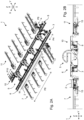
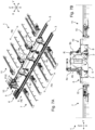
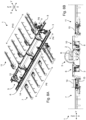
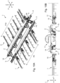
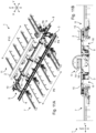
- the figures show examples of a fabrication assembly 1 for automated metal fabrication on an elongate metal workpiece 2 having a workpiece main axis W.
- the fabrication assembly 1 comprises a first track 3 extending horizontally and linearly, defining a horizontal X-direction X of the fabrication assembly 1.
- the fabrication assembly 1 comprises at least one first fabrication robot 4a, 4b coupled to the first track 3 so as to be movable along the first track 3 at least within a fabrication operational range F along the X-direction.
- the fabrication assembly 1 comprises a set 5 of rotator assemblies 5a-5d arranged, at least arrangeable, on one side of the first track 3 within the fabrication operational range F and configured to receive the elongate metal workpiece 2 with the workpiece main axis W substantially parallel to the X-direction, and to rotate the received elongate metal workpiece 2 about a rotator rotation axis R substantially parallel to the X-direction.
- the at least one first fabrication robot 4a, 4b is configured to perform metal fabrication action on the elongate metal workpiece 2 within the fabrication operational range F when the at least one first fabrication robot 4a, 4b is within the fabrication operational range F while the elongate metal workpiece 2 is received by the set 5 of rotator assemblies 5a-5d within the fabrication operational range F, for example as shown in Figs. 7A-B .
- the at least one first fabrication robot 4a, 4b is not shown in the side views of Figs. 2B , 3B , 4B , 5B , 6B , 8B , 9B , 10B , 11B .
- the fabrication assembly 1 further comprises a first set 6 of trolleys 6a-6d movable along the first track 3 at least within a workpiece transfer range T along the X-direction that at least partly overlaps with the fabrication operational range F, the first set 6 of trolleys 6a-6d being configured to receive the elongate metal workpiece 2 thereon with the workpiece main axis W substantially parallel to the X-direction.
- the fabrication assembly 1 is configured to transfer the elongate metal workpiece 2 between the first set 6 of trolleys 6a-6d and the set 5 of rotator assemblies 5a-5d within the workpiece transfer range T substantially in a Y-direction Y being a horizontal direction transverse to the X-direction X, for example as shown in Figs. 5A-6B .
- the figures also illustrate a method of automated metal fabrication on an elongate metal workpiece 2 having a workpiece main axis W.
- the method comprises: providing a fabrication assembly 1 as described herein; receiving the elongate metal workpiece 2 on the first set 6 of trolleys 6a-6d with the workpiece main axis W substantially parallel to the X-direction (see e.g. Figs.
- the first set 6 of trolleys 6a-6d bridges the first track 3 in the Y-direction, for example as shown in Fig. 2B .
- the workpiece 2 can advantageously cross the first track 3 in the Y-direction via the first set 6 of trolleys 6a-6d, for example from a cross transport assembly 7 discussed elsewhere herein.
- a crossing generally requires the workpiece to be suspended, e.g. from a hoisting assembly. The need for such a hoisting assembly can thus be obviated by provision of the first set 6 of trolleys 6a-6d.
- the first set 6 of trolleys 6a-6d is coupled to the first track 3.
- the at least one first fabrication robot 4a, 4b need not hamper the transfer of the workpiece 2 in the workpiece transfer range T. Since such fabrication robots may already be designed to move along such a track relatively quickly, they may thus be able to make room for transfer of the workpiece in a relatively time-efficient way.
- the at least one first fabrication robot 4a, 4b may for example be movable to outside the workpiece transfer range T at one end of the workpiece transfer range T, beyond which end the fabrication operational range F may then extend, e.g. as in the shown examples.
- the first set 6 of trolleys 6a-6d is positioned outside the fabrication operational range F while metal fabrication is performed by the fabrication assembly 1 using the at least one first fabrication robot 6a, 6b.
- the first set of trolleys and/or the at least one first fabrication robot may be adjustable, for example having a relatively large and versatile robot arm, such that the at least one first fabrication robot can reach the elongate metal workpiece for performing metal fabrication action thereon while one or more trolleys of the first set of trolleys are within the fabrication operational range.
- the first set 6 of trolleys 6a-6d defines a time-variable first trolley position range P6 along the X-direction depending on actual positions of the first set 6 of trolleys 6a-6d along the first track 3, wherein the at least one first fabrication robot 4a, 4b defines a time-variable first fabrication robot position range P4 along the X-direction depending on the actual position or positions of the at least one first fabrication robot 4a, 4b along the first track 3, wherein the fabrication assembly 1 is configured to prevent any overlap between the first trolley position range P6 and the first fabrication robot position range P4 at any given time.
- the first set 6 of trolleys 6a-6d and the at least one first fabrication robot 4a, 4b operate without hampering each other, wherein for example the at least one first fabrication robot 4a, 4b moves out of the workpiece transfer range T to one end of the track 3 when the first set 6 of trolleys 6a-6d moves into the fabrication operational range F from an opposite end of the track 3, and vice versa.
- the at least one first fabrication robot could be positioned or positionable within such a first trolley position range.
- the first trolley position range could then alternatively be time-invariable, although a time-variable range is still preferred.
- the at least one first fabrication robot may then be adjustable to extend only below a level at which the elongate metal workpiece is received on the first set of trolleys.
- the first set 6 of trolleys 6a-6d is movable along the first track 3 while the elongate metal workpiece 2 is received on the first set 6 of trolleys 6a-6d to thereby move the received elongate metal workpiece 2 along the X-direction.
- a position along the X-direction in which the workpiece 2 is received by the set 5 of rotator assemblies 5a-5d can advantageously be adjusted with respect to a position in which the workpiece 2 is initially received by the first set 6 of trolleys 6a-6d, so that a particularly versatile fabrication assembly 1 can be provided, in particular wherein such positions can be chosen in accordance with handling and/or processing constraints, such as regarding fabrication positions along the main axis W of the workpiece 2.
- Fig. 5A it can be seen that the first set 6 of trolleys 6a-6d with the workpiece 2 thereon has been moved along the track 3 with respect to Fig. 4A .
- a similar movement is seen for a subsequent workpiece 14 in Fig. 10A with respect to Fig. 9A .
- respective rotator positions of the set 5 of rotator assemblies 5a-5d along the X-direction are adjustable, for example along one or more tracks extending in the X-direction.
- the fabrication assembly 1 further comprises a first cross transport assembly 7 arranged at a distance from the set 5 of rotator assemblies 5a-5d and configured to transport an elongate metal workpiece 2 with respect to the first track 3 substantially in the Y-direction with the workpiece main axis W substantially parallel to the X-direction, wherein the first cross transport assembly 7 extends towards the first track 3 for direct transfer of the elongate metal workpiece 2 between the first cross transport assembly 7 and the first set 6 of trolleys 6a-6d substantially in the Y-direction.
- the workpiece 2 can advantageously be transported from an upstream process in a relatively compact and stable way, in particular with little or no movement in the X- and Z-directions (the Z-direction being the vertical direction). Moreover, a buffering of subsequent workpieces can be enabled along the Y-direction.
- the fabrication assembly 1 could be free from such a cross transport assembly, thereby providing a particularly compact fabrication assembly, wherein for example a workpiece may be positioned on the first set 6 of trolleys 6a, 6b using a hoisting assembly.
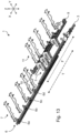
- Fig. 13 shows an example in which the first cross transport assembly 7 extends on a same lateral side of the first track 3 as the set 5 of rotator assemblies 5a-5d, thereby providing a more elongate overall configuration of the fabrication assembly 1 compared to the configuration of Figs. 1 to 11B , which may be more suitable for some sites depending on local spatial constraints.
- the first set 6 of trolleys 6a-6d can advantageously transport the workpiece along the X-direction between where the first cross transport assembly 7 is arranged and where the set 5 of rotator assemblies 5a-5d is arranged.
- a lifter refers to an assembly supported on a floor, optionally via one or more intermediate structures therebetween, and comprising a height-adjustable support structure on which at least a section of the workpiece can be supported.
- elements of the fabrication assembly 1, in particular the cross transport assemblies 7, 11, the trolleys 6a-6d, 11a-11d and the lifters 15, 16, 17, are preferably provided with chain mechanisms comprising drivable chains provided with cams configured to engage the workpiece 2 to move the workpiece along the Y-direction.
- chain mechanisms are known as such for horizontal transport of elongate metal workpieces transverse to their workpiece main axis along a support structure.
- the at least one second fabrication robot 9a, 9b is configured to perform metal fabrication action on the elongate metal workpiece 2 within the fabrication operational range F when the at least one second fabrication robot 9a, 9b is within the fabrication operational range F while the elongate metal workpiece 2 is received by the set 5 of rotator assemblies 5a-5d, for example as shown in Figs. 7A-B .
- the at least one second fabrication robot 9a, 9b is not shown in the side views of Figs. 2B , 3B , 4B , 5B , 6B , 8B , 9B , 10B , 11B .
- the second set 10 of trolleys 10a-10d is configured to receive the elongate metal workpiece 2 thereon with the workpiece main axis W substantially parallel to the X-direction, wherein the fabrication assembly 1 is configured to transfer the elongate metal workpiece 2 between the second set 10 of trolleys 10a-10d and the set 5 of rotator assemblies 5a-5d within the workpiece transfer range T substantially in the Y-direction.
- the second set 10 of trolleys 10a-10d defines a time-variable first trolley position range P10 along the X-direction depending on actual positions of the first set 10 of trolleys 10a-10d along the second track 8, wherein the at least one second fabrication robot 9a, 9b defines a time-variable first fabrication robot position range P9 along the X-direction depending on the actual position or positions of the at least one second fabrication robot 9a, 9b along the second track 8, wherein the fabrication assembly 1 is configured to prevent any overlap between the second trolley position range P10 and the second fabrication robot position range P9 at any given time.
- the fabrication assembly 1 further comprises a second cross transport assembly 11 arranged at a distance from the set 5 of rotator assemblies 5a-5d and configured to transport an elongate metal workpiece 2 with respect to the first and second tracks 3, 8 substantially in the Y-direction with the workpiece main axis W substantially parallel to the X-direction.
- the second cross transport assembly 11 extends towards the second track 8 for direct transfer of the elongate metal workpiece 2 between the second cross transport assembly 11 and the second set 10 of trolleys 10a-10d substantially in the Y-direction.
- the at least one second fabrication robot 9a, 9b is positioned outside the workpiece transfer range T while the elongate metal workpiece 2 is on the second set 10 of trolleys 10a-10d.
- the second set 10 of trolleys 10a-10d is positioned outside the fabrication operational range F while metal fabrication is performed by the fabrication assembly 1 using the at least one second fabrication robot 9a, 9b.
- the set 5 of rotator assemblies 5a-5d is adjustable between a first transfer state and a second transfer state.
- first transfer state see e.g. Figs. 5A-6B , 10A-11B
- the elongate metal workpiece 2 is transferrable between the set 5 of rotator assemblies 5a-5d and the first set 6 of trolleys 6a-6d on the first track 3 substantially in the Y-direction.
- second transfer state see e.g. Figs. 8A-9B
- the elongate metal workpiece 2 is transferrable between the set 5 of rotator assemblies 5a-5d and the second set 10 of trolleys 10a-10d on the second track 8 substantially in the Y-direction.
- the set 5 of rotator assemblies 5a-5d can exchange a workpiece 2 selectively with the first 6 or second 10 set of trolleys.
- the first transfer state and the second transfer state may differ by a rotator rotation of about 180 degrees about the rotator rotation axis R (indicated e.g. in Figs. 1 and 8B ) of the set 5 of rotator assemblies 5a-5d.
- the method further comprises receiving a subsequent elongate metal workpiece 14 on the first set 6 of trolleys 6a-6d while the fabrication assembly 1 transfers the elongate metal workpiece 2 from the set 5 of rotator assemblies 5a-5d to the second set 10 of trolleys 10a-10d.
- a relatively dense flow of workpieces can be enabled thereby, promoting efficiency.
- the first set 6 of trolleys 6a-6d with the second workpiece 14 thereon may be moved along the first track 3 to adjust the position of the second workpiece 14 along the X-direction and/or the second set 10 of trolleys 10a-10d with the first workpiece 2 thereon may be moved along the second track 8 to adjust the position of the first workpiece 2 along the X-direction.
- the method comprises adjusting at least one position of the set 5 of rotator assemblies 5a-5d along the X-direction, after the fabrication assembly 1 transfers the elongate metal workpiece 2 from the set 5 of rotator assemblies 5a-5d to the second set 10 of trolleys 10a-10d, before receipt of the subsequent elongate metal workpiece 14, in particular while the subsequent elongate metal workpiece 14 is on the first set 6 of trolleys 6a-6d.
- the at least one first fabrication robot 4a, 4b comprises at least one of a welding robot 4a and a handling robot 4b.
- the at least one second fabrication robot 9a, 9b may comprise at least one of a welding robot 9a, 9b and a handling robot.
- the second fabrication robots 9a, 9b are both welding robots, while the first fabrication robots 4a include one welding robot 4a and one handling robot 4b.
- the at least one first fabrication robot 4a, 4b is arranged along the first track 3 between the first set 6 of trolleys 6a-6d and a further first set 12 of trolleys 12a-12b.
- the at least one second fabrication robot 9a, 9b if provided, may be arranged along the second track 13 between the second set 10 of trolleys 10a-10d and a further second set 13 of trolleys 13a-13b.
- such an arrangement may enable parallel processing of workpieces, in particular relatively short workpieces, wherein the fabrication robots can perform metal fabrication actions on one workpiece, for example on a left side in Fig. 14 , while in parallel workpiece transfers are carried out, for example on a right side in Fig. 14 , and subsequently vice versa.
- the workpiece transfer range T and further workpiece transfer range T2 can mutually overlap, in particular to provide additional versatility in handling workpieces of different lengths.
Landscapes
- Engineering & Computer Science (AREA)
- Mechanical Engineering (AREA)
- Robotics (AREA)
- General Engineering & Computer Science (AREA)
- Manufacturing & Machinery (AREA)
- Quality & Reliability (AREA)
- Physics & Mathematics (AREA)
- General Physics & Mathematics (AREA)
- Automation & Control Theory (AREA)
- Manipulator (AREA)
- Automatic Assembly (AREA)
Claims (15)
- Fertigungsanordnung (1) für automatisierte Metallfertigung an einem länglichen Metallwerkstück (2) mit einer Werkstück-Hauptachse (W), umfassend:- eine erste Schiene (3), die sich horizontal und linear erstreckt und eine horizontale X-Richtung (X) der Fertigungsanordnung (1) definiert;- mindestens einen ersten Fertigungsroboter (4a, 4b), der mit der ersten Schiene (3) gekoppelt ist, sodass er entlang der ersten Schiene (3) zumindest innerhalb eines Fertigungsarbeitsbereichs (F) entlang der X-Richtung bewegbar ist; und- einen Satz (5) von Rotatoranordnungen (5a-5d), die zumindest anordenbar an einer Seite der ersten Schiene (3) innerhalb des Fertigungsarbeitsbereichs (F) angeordnet und dazu konfiguriert ist, das längliche Metallwerkstück (2) mit der Werkstück-Hauptachse (W) im Wesentlichen parallel zu der X-Richtung aufzunehmen, und das aufgenommene längliche Metallwerkstück (2) um eine Rotationsachse des Rotators (R) im Wesentlichen parallel zu der X-Richtung zu rotieren,wobei der mindestens eine erste Fertigungsroboter (4a, 4b) dazu konfiguriert ist, einen Metallfertigungsvorgang an dem länglichen Metallwerkstück (2) innerhalb des Fertigungsarbeitsbereichs (F) auszuführen, wenn sich der mindestens eine erste Fertigungsroboter (4a, 4b) innerhalb des Fertigungsarbeitsbereichs (F) befindet, während das längliche Metallwerkstück (2) von dem Satz (5) von Rotatoranordnungen (5a-5d) innerhalb des Fertigungsarbeitsbereichs (F) aufgenommen ist,dadurch gekennzeichnet, dass die Fertigungsanordnung (1) ferner einen ersten Satz (6) von Transportwagen (6a-6d) umfasst, der entlang der ersten Schiene (3) zumindest innerhalb eines Werkstück-Transferbereichs (T) entlang der X-Richtung ist, der sich zumindest teilweise mit dem Fertigungsarbeitsbereich (F) überlappt, der erste Satz (6) von Transportwagen (6a-6d) dazu konfiguriert ist, das längliche Metallwerkstück (2) darauf mit der Werkstück-Hauptachse (W) im Wesentlichen parallel zu der X-Richtung aufzunehmen, wobei die Fertigungsanordnung (1) dazu konfiguriert ist, das längliche Metallwerkstück (2) zwischen dem ersten Satz (6) von Transportwagen (6a-6d) und dem Satz (5) von Rotatoranordnungen (5a-5d) innerhalb des Werkstück-Transferbereichs (T) im Wesentlichen in einer Y-Richtung (Y) zu transferieren, die eine horizontale Richtung quer zu der X-Richtung (X) ist.
- Fertigungsanordnung nach Anspruch 1, wobei der mindestens eine erste Fertigungsroboter (4a, 4b) entlang der ersten Schiene (3) aus dem Werkstück-Transferbereich (T) heraus bewegbar ist,
und/oder wobei der erste Satz (6) von Transportwagen (6a-6d) entlang der ersten Schiene (3) aus dem Fertigungsarbeitsbereich (F) heraus bewegbar ist. - Fertigungsanordnung nach einem der vorstehenden Ansprüche, wobei der erste Satz (6) von Transportwagen (6a-6d) mit der ersten Schiene (3) gekoppelt ist,
und/oder wobei der erste Satz (6) von Transportwagen (6a-6d) die erste Schiene (3) in der Y-Richtung überbrückt. - Fertigungsanordnung nach einem der vorstehenden Ansprüche, wobei der erste Satz (6) von Transportwagen (6a-6d) einen zeitvariablen ersten Transportwagen-Positionsbereich (P6) entlang der X-Richtung in Abhängigkeit von den tatsächlichen Positionen des ersten Satzes (6) von Transportwagen (6a-6d) entlang der ersten Schiene (3) definiert, wobei der mindestens eine erste Fertigungsroboter (4a, 4b) einen zeitvariablen ersten Fertigungsroboter-Positionsbereich (P4) entlang der X-Richtung in Abhängigkeit von der tatsächlichen Position oder den tatsächlichen Positionen des mindestens einen ersten Fertigungsroboters (4a, 4b) entlang der ersten Schiene (3) definiert, wobei die Fertigungsanordnung (1) dazu konfiguriert ist, eine Überlappung zwischen dem ersten Transportwagen-Positionsbereich (P6) und dem ersten Fertigungsroboter-Positionsbereich (P4) zu jedem Zeitpunkt zu verhindern.
- Fertigungsanordnung nach einem der vorstehenden Ansprüche, wobei der erste Satz (6) von Transportwagen (6a-6d) entlang der ersten Schiene (3) bewegbar ist, während das längliche Metallwerkstück (2) auf dem ersten Satz (6) von Transportwagen (6a-6d) aufgenommen ist, um dadurch das aufgenommene längliche Metallwerkstück (2) entlang der X-Richtung zu bewegen.
- Fertigungsanordnung nach einem der vorstehenden Ansprüche, ferner umfassend eine erste Quertransportanordnung (7), die in einem Abstand von dem Satz (5) von Rotatoranordnungen (5a-5d) angeordnet und dazu konfiguriert ist, ein längliches Metallwerkstück (2) in Bezug auf die erste Schiene (3) im Wesentlichen in der Y-Richtung mit der Werkstück-Hauptachse (W) im Wesentlichen parallel zu der X-Richtung zu transportieren,
wobei sich die erste Quertransportanordnung (7) in Richtung der ersten Schiene (3) erstreckt, um das längliche Metallwerkstück (2) zwischen der ersten Quertransportanordnung (7) und dem ersten Satz (6) von Transportwagen (6a-6d) im Wesentlichen in der Y-Richtung direkt zu transferieren. - Fertigungsanordnung nach einem der vorstehenden Ansprüche, umfassend eine zweite Schiene (8), die sich im Wesentlichen parallel zu der ersten Schiene (3) auf einer der ersten Schiene (3) gegenüberliegenden Seite des Satzes (5) von Rotatoranordnungen (5a-5d) erstreckt, wobei mindestens ein zweiter Fertigungsroboter (9a, 9b) mit der zweiten Schiene (8) gekoppelt ist, sodass er entlang der zweiten Schiene (8) bewegbar ist, wobei ein zweiter Satz (10) von Transportwagen (10a-10d) entlang der zweiten Schiene (8) bewegbar ist,wobei der mindestens eine zweite Fertigungsroboter (9a, 9b) dazu konfiguriert ist, einen Metallfertigungsvorgang an dem länglichen Metallwerkstück (2) innerhalb des Fertigungsarbeitsbereichs (F) auszuführen, wenn sich der mindestens eine zweite Fertigungsroboter (9a, 9b) innerhalb des Fertigungsarbeitsbereichs (F) befindet, während das längliche Metallwerkstück (2) von dem Satz (5) von Rotatoranordnungen (5a-5d) aufgenommen ist,wobei der zweite Satz (10) von Transportwagen (10a-10d) dazu konfiguriert ist, das längliche Metallwerkstück (2) mit der Werkstück-Hauptachse (W) im Wesentlichen parallel zu der X-Richtung aufzunehmen, wobei die Fertigungsanordnung (1) dazu konfiguriert ist, das längliche Metallwerkstück (2) zwischen dem zweiten Satz (10) von Transportwagen (10a-10d) und dem Satz (5) von Rotatoranordnungen (5a-5d) innerhalb des Werkstück-Transferbereichs (T) im Wesentlichen in der Y-Richtung zu transferieren.
- Fertigungsanordnung nach Anspruch 7, wobei der Satz (5) von Rotatoranordnungen (5a-5d) zwischen einem ersten Transferzustand und einem zweiten Transferzustand einstellbar ist,wobei in dem ersten Transferzustand das längliche Metallwerkstück (2) zwischen dem Satz (5) von Rotatoranordnungen (5a-5d) und dem ersten Satz (6) von Transportwagen (6a-6d) auf der ersten Schiene (3) im Wesentlichen in der Y-Richtung transferierbar ist,wobei in dem zweiten Transferzustand das längliche Metallwerkstück (2) zwischen dem Satz (5) von Rotatoranordnungen (5a-5d) und dem zweiten Satz (10) von Transportwagen (10a-10d) auf der zweiten Schiene (8) im Wesentlichen in der Y-Richtung transferierbar ist.
- Fertigungsanordnung nach Anspruch 7 oder 8, in Abhängigkeit von Anspruch 6, wobei die Fertigungsanordnung (1) ferner eine zweite Quertransportanordnung (11) umfasst, die in einem Abstand von dem Satz (5) von Rotatoranordnungen (5a-5d) angeordnet und dazu konfiguriert ist, ein längliches Metallwerkstück (2) in Bezug auf die erste und zweite Schiene (3, 8) im Wesentlichen in der Y-Richtung mit der Werkstück-Hauptachse (W) im Wesentlichen parallel zu der X-Richtung zu transportieren,
wobei sich die zweite Quertransportanordnung (11) in Richtung der zweiten Schiene (8) erstreckt, um das längliche Metallwerkstück (2) zwischen der zweiten Quertransportanordnung (11) und dem zweiten Satz (10) von Transportwagen (10a-10d) im Wesentlichen in der Y-Richtung direkt zu transferieren. - Fertigungsanordnung nach einem der vorstehenden Ansprüche, wobei der mindestens eine erste Fertigungsroboter (4a, 4b) entlang der ersten Schiene (3) zwischen dem ersten Satz (6) von Transportwagen (6a-6d) und einem weiteren ersten Satz (12) von Transportwagen (12a-12b) angeordnet ist,und/oder wobei der mindestens eine erste Fertigungsroboter (4a, 4b) mindestens einen von einem Schweißroboter (4a) und einem Handhabungsroboter (4b) umfasst,und/oder wobei der Werkstück-Transferbereich (T) mindestens 50 %, vorzugsweise mindestens 60 %, noch bevorzugter mindestens 70 %, beispielsweise etwa 80 %, des Fertigungsarbeitsbereichs (F) überlappt,und/oder wobei die Fertigungsanordnung mindestens einen Satz von Hebevorrichtungen (15, 16, 17) umfasst, der dazu konfiguriert ist, eine vertikale Ebene des länglichen Metallwerkstücks (2) zum Transferieren des Werkstücks (2) in der Y-Richtung zwischen Elementen der Fertigungsanordnung (1) einzustellen.
- Verfahren der automatisierten Metallfertigung an einem länglichen Metallwerkstück (2) mit einer Werkstück-Hauptachse (W), umfassend:- Bereitstellen einer Fertigungsanordnung (1) nach einem der vorstehenden Ansprüche;- Aufnehmen des länglichen Metallwerkstücks (2) auf dem ersten Satz (6) von Transportwagen (6a-6d) mit der Werkstück-Hauptachse (W) im Wesentlichen parallel zu der X-Richtung;- Veranlassen der Fertigungsanordnung (1), das längliche Metallwerkstück (2) von dem ersten Satz (6) von Transportwagen (6a-6d) zu dem Satz (5) von Rotatoranordnungen (5a-5d) innerhalb des Werkstück-Transferbereichs (T) im Wesentlichen in der Y-Richtung zu transferieren, wodurch das längliche Metallwerkstück (2) von dem Satz (5) von Rotatoranordnungen (5a-5b) aufgenommen wird; und- Veranlassen der Fertigungsanordnung (1), eine Metallfertigung an dem länglichen Metallwerkstück (2) innerhalb des Fertigungsarbeitsbereichs (F) durchzuführen, während das längliche Metallwerkstück (2) von dem Satz (5) von Rotatoranordnungen (5a-5d) aufgenommen ist.
- Verfahren nach Anspruch 11, wobei der mindestens eine erste Fertigungsroboter (4a, 4b) außerhalb des Werkstück-Transferbereichs (T) positioniert ist, während sich das längliche Metallwerkstück (2) auf dem ersten Satz (6) von Transportwagen (6a-6d) befindet,
und/oder wobei der erste Satz (6) von Transportwagen (6a-6d) außerhalb des Fertigungsarbeitsbereichs (F) positioniert ist, während die Metallfertigung durch die Fertigungsanordnung (1) unter Verwendung des mindestens einen ersten Fertigungsroboters (6a, 6b) durchgeführt wird. - Verfahren nach einem der Ansprüche 11 bis 12, wobei die Fertigungsanordnung (1) nach Anspruch 7 oder einem von Anspruch 7 abhängigen Anspruch ist, wobei das Verfahren ferner Folgendes umfasst:- Veranlassen der Fertigungsanordnung (1), das längliche Metallwerkstück (2) von dem Satz (5) von Rotatoranordnungen (5a-5d) zu dem zweiten Satz (10) von Transportwagen (10a-10d) innerhalb des Werkstück-Transferbereichs (T) im Wesentlichen in der Y-Richtung zu transferieren,optional, wobei der mindestens eine zweite Fertigungsroboter (9a, 9b) außerhalb des Werkstück-Transferbereichs (T) positioniert ist, während sich das längliche Metallwerkstück (2) auf dem zweiten Satz (10) von Transportwagen (10a-10d) befindet.
- Verfahren nach Anspruch 13, wobei der zweite Satz (10) von Transportwagen (10a-10d) außerhalb des Fertigungsarbeitsbereichs (F) positioniert ist, während die Metallfertigung durch die Fertigungsanordnung (1) unter Verwendung des mindestens einen zweiten Fertigungsroboters (9a, 9b) durchgeführt wird.
- Verfahren nach einem der Ansprüche 13 bis 14, ferner umfassend das Aufnehmen eines nachfolgenden länglichen Metallwerkstücks (14) auf dem ersten Satz (6) von Transportwagen (6a-6d), während die Fertigungsanordnung (1) das längliche Metallwerkstück (2) von dem Satz (5) von Rotatoranordnungen (5a-5d) zu dem zweiten Satz (10) von Transportwagen (10a-10d) transferiert.
und optional ferner umfassend das Einstellen mindestens einer Position des Satzes (5) von Rotatoranordnungen (5a-5d) entlang der X-Richtung, nachdem die Fertigungsanordnung (1) das längliche Metallwerkstück (2) von dem Satz (5) von Rotatoranordnungen (5a-5d) zu dem zweiten Satz (10) von Transportwagen (10a-10d) transferiert hat, während sich das nachfolgende längliche Metallwerkstück (14) auf dem ersten Satz (6) von Transportwagen (6a-6d) befindet.
Applications Claiming Priority (2)
| Application Number | Priority Date | Filing Date | Title |
|---|---|---|---|
| NL2034119A NL2034119B1 (en) | 2023-02-09 | 2023-02-09 | Fabrication assembly and method of automated metal fabrication |
| PCT/NL2024/050051 WO2024167399A1 (en) | 2023-02-09 | 2024-02-02 | Fabrication assembly and method of automated metal fabrication |
Publications (3)
| Publication Number | Publication Date |
|---|---|
| EP4433256A1 EP4433256A1 (de) | 2024-09-25 |
| EP4433256B1 true EP4433256B1 (de) | 2025-07-09 |
| EP4433256C0 EP4433256C0 (de) | 2025-07-09 |
Family
ID=86007100
Family Applications (1)
| Application Number | Title | Priority Date | Filing Date |
|---|---|---|---|
| EP24703667.6A Active EP4433256B1 (de) | 2023-02-09 | 2024-02-02 | Herstellungsanordnung und verfahren zur automatisierten metallherstellung |
Country Status (5)
| Country | Link |
|---|---|
| US (1) | US12269174B2 (de) |
| EP (1) | EP4433256B1 (de) |
| NL (1) | NL2034119B1 (de) |
| PL (1) | PL4433256T3 (de) |
| WO (1) | WO2024167399A1 (de) |
Family Cites Families (3)
| Publication number | Priority date | Publication date | Assignee | Title |
|---|---|---|---|---|
| ATE552943T1 (de) * | 2008-02-15 | 2012-04-15 | Me C Al S P A | Vorrichtung zum bewegen von zu bearbeitenden profilen |
| NL2022698B1 (en) * | 2019-03-08 | 2020-09-17 | Voortman Steel Machinery Holding B V | A method of processing profiles in a profile processing assembly and a profile infeed assembly for transporting profiles towards a working machine |
| JP7227073B2 (ja) * | 2019-05-23 | 2023-02-21 | ファナック株式会社 | ワーク回転装置およびロボットシステム |
-
2023
- 2023-02-09 NL NL2034119A patent/NL2034119B1/en active
-
2024
- 2024-02-02 US US18/727,438 patent/US12269174B2/en active Active
- 2024-02-02 EP EP24703667.6A patent/EP4433256B1/de active Active
- 2024-02-02 PL PL24703667.6T patent/PL4433256T3/pl unknown
- 2024-02-02 WO PCT/NL2024/050051 patent/WO2024167399A1/en not_active Ceased
Also Published As
| Publication number | Publication date |
|---|---|
| EP4433256A1 (de) | 2024-09-25 |
| NL2034119B1 (en) | 2024-08-29 |
| PL4433256T3 (pl) | 2025-09-22 |
| WO2024167399A1 (en) | 2024-08-15 |
| US12269174B2 (en) | 2025-04-08 |
| US20240416521A1 (en) | 2024-12-19 |
| EP4433256C0 (de) | 2025-07-09 |
Similar Documents
| Publication | Publication Date | Title |
|---|---|---|
| RU2110349C1 (ru) | Поточная линия для изготовления коробчатых конструкций из стальных листов, поворотно-гибочный пресс для изготовления коробчатых конструкций из стальных листов и манипулятор листов к гибочному прессу | |
| JP2022527957A (ja) | ワークを自動的に反転させ加工する2つのガントリワークステーションを組み合わせた加工システム | |
| US6355906B1 (en) | Production system using combination jigs and jig replacement method and apparatus therefor | |
| JP2009072840A (ja) | ハンドリング装置 | |
| KR20130046439A (ko) | 반송 로봇 | |
| RU2355579C2 (ru) | Конвейер для транспортировки заготовок в прессе | |
| CN104889643B (zh) | 一种汽车白车身焊接定位系统 | |
| CN112059521B (zh) | 用于轻型钢结构自动焊接生产流水线的变位系统 | |
| JP2017105223A (ja) | ワーク反転搬送装置 | |
| EP4433256B1 (de) | Herstellungsanordnung und verfahren zur automatisierten metallherstellung | |
| JP5885871B1 (ja) | ワーク着脱装置 | |
| JP6098925B2 (ja) | 大型枠組構造物の溶接装置 | |
| CN103659262B (zh) | 双边式装配变位机 | |
| CN212688732U (zh) | 抢修梁架设装置 | |
| CN114701814A (zh) | 一种钢构件加工周转小车 | |
| JP2016098069A (ja) | オーバーヘッドコンベア装置 | |
| CN208391301U (zh) | 一种双拼焊矫生产线 | |
| CN218555996U (zh) | 一种住宅建筑钢结构构件自动化装配生产线设备 | |
| CN202607664U (zh) | 一种机器人驱动结构 | |
| CN223920437U (zh) | 一种工件组装用换向移料组件 | |
| KR100774392B1 (ko) | 자동차 구조 작업장의 시설 구성 시스템 | |
| KR20050097304A (ko) | 작업 유닛의 이송 장치 | |
| EP1110680A1 (de) | Portalwagen mit Tragvorrichtung für Roboter | |
| JP2017154882A (ja) | 吊りビーム装置 | |
| JPS6233070A (ja) | パネル自動溶接装置 |
Legal Events
| Date | Code | Title | Description |
|---|---|---|---|
| STAA | Information on the status of an ep patent application or granted ep patent |
Free format text: STATUS: UNKNOWN |
|
| STAA | Information on the status of an ep patent application or granted ep patent |
Free format text: STATUS: THE INTERNATIONAL PUBLICATION HAS BEEN MADE |
|
| PUAI | Public reference made under article 153(3) epc to a published international application that has entered the european phase |
Free format text: ORIGINAL CODE: 0009012 |
|
| STAA | Information on the status of an ep patent application or granted ep patent |
Free format text: STATUS: REQUEST FOR EXAMINATION WAS MADE |
|
| 17P | Request for examination filed |
Effective date: 20240603 |
|
| AK | Designated contracting states |
Kind code of ref document: A1 Designated state(s): AL AT BE BG CH CY CZ DE DK EE ES FI FR GB GR HR HU IE IS IT LI LT LU LV MC ME MK MT NL NO PL PT RO RS SE SI SK SM TR |
|
| GRAP | Despatch of communication of intention to grant a patent |
Free format text: ORIGINAL CODE: EPIDOSNIGR1 |
|
| STAA | Information on the status of an ep patent application or granted ep patent |
Free format text: STATUS: GRANT OF PATENT IS INTENDED |
|
| DAV | Request for validation of the european patent (deleted) | ||
| DAX | Request for extension of the european patent (deleted) | ||
| INTG | Intention to grant announced |
Effective date: 20250203 |
|
| GRAS | Grant fee paid |
Free format text: ORIGINAL CODE: EPIDOSNIGR3 |
|
| GRAA | (expected) grant |
Free format text: ORIGINAL CODE: 0009210 |
|
| STAA | Information on the status of an ep patent application or granted ep patent |
Free format text: STATUS: THE PATENT HAS BEEN GRANTED |
|
| AK | Designated contracting states |
Kind code of ref document: B1 Designated state(s): AL AT BE BG CH CY CZ DE DK EE ES FI FR GB GR HR HU IE IS IT LI LT LU LV MC ME MK MT NL NO PL PT RO RS SE SI SK SM TR |
|
| REG | Reference to a national code |
Ref country code: GB Ref legal event code: FG4D |
|
| REG | Reference to a national code |
Ref country code: CH Ref legal event code: EP |
|
| REG | Reference to a national code |
Ref country code: IE Ref legal event code: FG4D |
|
| REG | Reference to a national code |
Ref country code: DE Ref legal event code: R096 Ref document number: 602024000292 Country of ref document: DE |
|
| U01 | Request for unitary effect filed |
Effective date: 20250808 |
|
| U07 | Unitary effect registered |
Designated state(s): AT BE BG DE DK EE FI FR IT LT LU LV MT NL PT RO SE SI Effective date: 20250821 |
|
| PG25 | Lapsed in a contracting state [announced via postgrant information from national office to epo] |
Ref country code: IS Free format text: LAPSE BECAUSE OF FAILURE TO SUBMIT A TRANSLATION OF THE DESCRIPTION OR TO PAY THE FEE WITHIN THE PRESCRIBED TIME-LIMIT Effective date: 20251109 |
|
| PG25 | Lapsed in a contracting state [announced via postgrant information from national office to epo] |
Ref country code: NO Free format text: LAPSE BECAUSE OF FAILURE TO SUBMIT A TRANSLATION OF THE DESCRIPTION OR TO PAY THE FEE WITHIN THE PRESCRIBED TIME-LIMIT Effective date: 20251009 |
|
| PG25 | Lapsed in a contracting state [announced via postgrant information from national office to epo] |
Ref country code: HR Free format text: LAPSE BECAUSE OF FAILURE TO SUBMIT A TRANSLATION OF THE DESCRIPTION OR TO PAY THE FEE WITHIN THE PRESCRIBED TIME-LIMIT Effective date: 20250709 |
|
| PG25 | Lapsed in a contracting state [announced via postgrant information from national office to epo] |
Ref country code: GR Free format text: LAPSE BECAUSE OF FAILURE TO SUBMIT A TRANSLATION OF THE DESCRIPTION OR TO PAY THE FEE WITHIN THE PRESCRIBED TIME-LIMIT Effective date: 20251010 |
|
| PG25 | Lapsed in a contracting state [announced via postgrant information from national office to epo] |
Ref country code: RS Free format text: LAPSE BECAUSE OF FAILURE TO SUBMIT A TRANSLATION OF THE DESCRIPTION OR TO PAY THE FEE WITHIN THE PRESCRIBED TIME-LIMIT Effective date: 20251009 |
|
| PG25 | Lapsed in a contracting state [announced via postgrant information from national office to epo] |
Ref country code: ES Free format text: LAPSE BECAUSE OF FAILURE TO SUBMIT A TRANSLATION OF THE DESCRIPTION OR TO PAY THE FEE WITHIN THE PRESCRIBED TIME-LIMIT Effective date: 20250709 |