EP4433236B1 - Biegemaschine - Google Patents
Biegemaschine Download PDFInfo
- Publication number
- EP4433236B1 EP4433236B1 EP22817898.4A EP22817898A EP4433236B1 EP 4433236 B1 EP4433236 B1 EP 4433236B1 EP 22817898 A EP22817898 A EP 22817898A EP 4433236 B1 EP4433236 B1 EP 4433236B1
- Authority
- EP
- European Patent Office
- Prior art keywords
- bending
- holding device
- bending machine
- tool
- machine according
- Prior art date
- Legal status (The legal status is an assumption and is not a legal conclusion. Google has not performed a legal analysis and makes no representation as to the accuracy of the status listed.)
- Active
Links
Images


Classifications
-
- B—PERFORMING OPERATIONS; TRANSPORTING
- B21—MECHANICAL METAL-WORKING WITHOUT ESSENTIALLY REMOVING MATERIAL; PUNCHING METAL
- B21D—WORKING OR PROCESSING OF SHEET METAL OR METAL TUBES, RODS OR PROFILES WITHOUT ESSENTIALLY REMOVING MATERIAL; PUNCHING METAL
- B21D5/00—Bending sheet metal along straight lines, e.g. to form simple curves
- B21D5/02—Bending sheet metal along straight lines, e.g. to form simple curves on press brakes without making use of clamping means
- B21D5/0209—Tools therefor
- B21D5/0236—Tool clamping
Definitions
- the invention relates to a bending machine for forming workpieces by bending.
- Bending machines such as for example press brakes, are often designed for operation with different bending tools, which implement the bending of a corresponding workpiece during operation.
- the exchange of bending tools requires the opening or closing of a corresponding holding device on the bending machine.
- holding devices are known that must be opened or closed manually by a human operator.
- Such manual holding devices require the physical effort of the operator and require long changeover times for the bending tools.
- Automatic holding devices are also known from the prior art, in which, with a suitable actuator, the holding device can be released to remove the bending tool or closed to fix the bending tool.
- a suitable actuator for example, hydraulic, pneumatic, or electromechanical actuators are used as actuators.
- Automatic holding devices relieve the human operator, but result in high manufacturing costs and are prone to errors.
- DE 30 26 847 A1 discloses a press brake in which a bending tool is releasably clamped in a tool holder via a hydraulically or pneumatically pressurisable swellable body.
- DE 195 13 576 A1 discloses a bending press with a clamping device for the releasable fastening of a tool, wherein the clamping device is hydraulically operable.
- WO 2015/164483 A1 describes a tool holder in which the tool is fixed using a clamping device that is actuated by a cylinder pressurised with compressed air.
- Document US 2011/247389 A1 discloses a clamping device for clamping a tool in a press brake according to the preamble of claim 1.
- the clamping device includes a part receiving the tool as well as an actuated member and an engaging member to be brought into contact with the tool.
- the clamping device is provided with a transmission placed between the actuated member and the engaging member.
- the actuated member can be pneumatically or electrically or hydraulically driven.
- the transmission can include a wedge-shaped member or a lever.
- Document WO 2020/225761 A1 discloses a bending machine for metal sheets comprising a punch means which includes an upper tool-holding cross piece.
- the cross piece comprises a locking means having a plurality of movable locking elements and configured to engage and lock upper bending tools in a locking configuration so as to prevent any movement of the upper bending tools.
- the locking elements are driven linearly between the locking configuration and a releasing configuration in which the locking elements do not engage and lock the upper bending tools.
- the object of the invention is to provide a bending machine having a holding device for bending tools, wherein the holding device enables an automatic fixing and release of the bending tools in a simple manner.
- the bending machine according to the invention has a bending beam which can be moved in at least one working direction of the bending machine to form a workpiece by bending along a bending line, wherein the bending line runs in a width direction of the bending machine.
- the bending machine contains a holding device for fixing at least one bending tool on the bending machine.
- a release means is also provided on the bending machine which, when it is actuated, transfers the holding device from a closed position in which the at least one bending tool is fixed to an open position in which the at least one bending tool is released.
- the bending machine according to the invention is designed such that a movement of the bending beam towards a predetermined release position actuates the release means when the predetermined release position is reached.
- the bending machine according to the invention has the advantage that the movement of the bending beam is used not only for the purposes of the bending of the workpiece, but also to release bending tools held in the bending machine. In this way, a simple mechanism is created to allow a changing of bending tools on the bending machine.
- the at least one bending tool is held on the bending beam when the holding device is in the closed position. Nevertheless, it is also possible that the at least one bending tool is held on a bending beam other than the bending beam, the movement of which actuates the release means.
- the at least one bending tool can be fixed in different ways depending on the design of the bending machine.
- the holding device provided in the bending machine is designed for fixing the at least one bending tool in a positive and/or non-positive manner.
- a form-fitting fixing can be effected, for example, via a slide control.
- the holding device exerts a holding force on the at least one bending tool to fix same on the bending machine, wherein the holding force on the at least one bending tool is terminated when the release means is actuated and the holding device is thereby brought into the open position in which the at least one bending tool is released.
- the bending machine according to the invention is designed such that when the predetermined release position is reached, the movement of the bending beam generates a release force which is exerted on the holding device by the release means to cancel the fixing of the at least one bending tool.
- This variant of the invention is preferably combined with a non-positive fixing of the at least one bending tool, so that the release force terminates the holding force exerted by the holding device on the at least one bending tool.
- the release means can generate the release force directly by mechanical action on the holding device.
- the release means can comprise a hydraulic circuit, for example, which is switched on when the release position is reached and then generates the release force via hydraulic pressure.
- the bending machine according to the invention is designed such that the movement of the bending beam towards the predetermined release position is a movement in the working direction of the bending machine.
- This embodiment is preferably used when the bending machine is a press brake.
- the movement of the bending beam towards the predetermined release position is a movement in a direction deviating from the working direction, wherein the deviating direction preferably corresponds to the width direction of the bending machine.
- This variant is preferably used when the bending machine is a panel bender.
- the release means is immovably attached to the bending machine, whereas the holding device together with the bending beam can be moved towards the predetermined release position.
- the interaction of the release means with the holding device is implemented in a simple manner.
- the holding device is preferably provided on the bending beam, the movement of which actuates the release means, to hold the at least one bending tool on this bending beam.
- the release means can also be movable with the bending beam, the movement of which actuates the release means, whereas the holding device is immovably attached to the bending machine to hold the at least one bending tool on a (stationary) bending beam other than the bending beam, the movement of which actuates the release means.
- the release means contains one or more contact elements, preferably one or more wedges. These contact elements are arranged such that when the predetermined release position is reached, they mechanically contact the holding device and thereby terminate the fixing of the at least one bending tool.
- the release of the at least one bending tool can be achieved by a simple mechanical structure.
- the exertion of a holding force generated by the holding device on the at least one bending tool is terminated by means of the contact element or elements.
- a respective contact element is designed such that when the predetermined release position is reached, it presses against at least one contact surface of the holding device and in this way triggers a movement on the holding device, whereby the fixing of the at least one bending tool is terminated.
- the exertion of a holding force generated by the holding device on the at least one bending tool is preferably terminated.
- the holding device is a clamping device which is designed so as to exert a holding force in the form of a clamping force on the at least one bending tool to fix the at least one bending tool.
- the holding device comprises one or more elastic means, which are pretensioned in the holding device to generate thereby a holding force for fixing the at least one bending tool.
- the elastic means can be configured differently, for example as one or more springs, such as for example disc springs, and/or as one or more elastomers and the like.
- the holding device comprises one or more loss prevention devices to hold the at least one bending tool loosely in the holding device when the holding device is open.
- the holding device comprises one or more positioning means to ensure that the at least one bending tool moves into a predetermined position when the predetermined release position is reached, in which the at least one bending tool is held by the holding device.
- a sensor system is provided in the bending machine according to the invention, which is configured to detect the approach of the bending beam towards the predetermined release position as a detection event.
- the bending machine is preferably designed such that when the detection event is detected, a message is output via a user interface of the bending machine, such as for example a display. In this way, an operator of the bending machine is informed that the bending machine is in a state in which the bending tools can be changed.
- the release means can be moved into a parked position on the bending machine, in which the release means cannot be actuated by moving the bending beam. In this way, an unintentional loosening of the fixing of the at least one bending tool can be prevented.
- the bending machine according to the invention is a press brake for freely bending a workpiece between a movable upper beam and a stationary lower beam.
- the bending beam, the movement of which actuates the release means, is the upper beam.
- the holding device is provided on the upper beam to hold the at least one bending tool on the upper beam, wherein the release means is arranged to be immovably adjacent to the upper beam and the predetermined release position is reached due to the movement of the upper beam in the working direction away from the lower beam.
- the bending machine according to the invention is a panel bender, which is configured such that the workpiece-in contrast to free bending in a press brake-is fixed during bending.
- the holding device is provided on the bending beam, the movement of which actuates the release means to hold the at least one bending tool on this bending beam, wherein the predetermined release position is outside a working area in which the bending by the bending beam takes place.
- the bending beam can preferably be moved into the predetermined release position in the width direction of the panel bender.
- this includes a primary bending beam, which is movable exclusively in the working direction and perpendicular to the plane spanned by the working direction and the width direction, and a secondary bending beam, which is the bending beam, the movement of which actuates the release means, wherein the secondary bending beam is movably arranged on the primary bending beam in the width direction.
- the secondary bending beam thus follows the movement of the primary bending beam, but can also be moved in the width direction relative to the primary bending beam.
- the spatial orientation of the corresponding bending machine is illustrated by a Cartesian coordinate system with an x-axis, y-axis and z-axis.
- the z-axis represents the height direction
- the y-axis represents the width direction of the bending machine in which the bending line runs
- the x-axis represents the direction perpendicular to the y-axis and z-axis.
- the workpiece to be bent is introduced into the bending machine by an operator or, in some cases, automatically.
- a first embodiment of a bending machine according to the invention in the form of a press brake is described below.
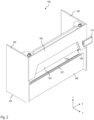
- This press brake is shown in plan view in Fig. 1 and in perspective view in Fig. 2 and is indicated by the symbol 100. Only the components of the press brake that are essential to the invention are shown.
- the press brake 100 comprises a machine body 101 fixed to the floor, which comprises two side stands 102, 103 and a front plate 104.
- a stationary lower beam 106 and an upper beam 105 that can be moved in the z-direction extend in a manner known per se between the side stands 102 and 103.
- the upper beam represents a bending beam within the meaning of the claims.
- bending tools are fixed to the underside of the upper beam 105 for the corresponding bending process, wherein two such bending tools 109 are provided according to Figs. 1 and 2 .
- the press brake 100 is used for bending sheet metal.
- the sheet metal is introduced along the x-axis into the working area between lower beam 106 and upper beam 105, and then the upper beam 105 is moved downwards to form the sheet metal, so that the bending tools 109 press into the sheet metal and form it appropriately.
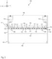
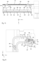
- the movement of the upper beam 105 is effected by means of hydraulics in the form of two hydraulic cylinders 112, 112', which can be seen from the rear view of Fig. 3 .
- a control device 110 indicated only schematically in Fig. 1
- a user interface 111 in the form of a touch display, which is arranged in the right-hand area of the press brake on the front plate 104.
- the corresponding bending tools 109 Since large forces act on the sheet during the bending process, the corresponding bending tools 109 must be firmly fixed in the upper beam 105. At the same time, however, it must also be ensured that the bending tools 109 can be exchanged. This is ensured by a holding device 113 which fixes the corresponding bending tools 109 to the upper beam 105, wherein it is possible for the holding device to be opened with a release means 116 to remove the bending tools.
- Fig. 3 shows a press brake 100 in a plan view from the rear.
- Fig. 3 shows the already mentioned hydraulic cylinders 112 and 112', which act in a manner known per se on the edge regions of the upper beam 105 and thereby move the upper beam up or down.
- Fig. 3 also shows the above-mentioned holding device 113, which in the embodiment described here is designed as a clamping device.
- Fig. 3 also shows a sensor system 108 that is indicated only schematically.
- This sensor system detects when the contact elements 117 are in a position within the holding device 113 due to an upward movement of the upper beam 105, so that the clamping of the bending tools 109 is released. When this position is detected, a corresponding message is generated on the user interface 111 so that the operator knows that the bending tool 109 is now released and can be removed.
- a message can be output via the user interface 111 if the sensor system 108 detects that, due to the downward movement of the upper beam 105, the contact elements 117 have moved so far out of the holding device 113 that they can no longer effect the opening of the holding device 113, and the bending tools 109 are fixed to the upper beam 105.
- the corresponding message shows the user that the corresponding bending process can now be carried out.
- Fig. 4 and Fig. 5 show sectional views in the closed state of the holding device 113, wherein the section in Fig. 4 in the xz-plane runs centrally through the left-hand bending tool 109 in Fig. 3 , whereas the section in Fig. 5 in the xz-plane runs centrally through the left-most wedge 117 of Fig. 3 .
- the contact element 117 is fastened to the transverse strut 118 via fastening means in the form of screws 120.
- the contact element 117 has a wedge-shaped tip which is moved into the holding device 113 to open it, as will be described in more detail further below.
- the holding device 113 comprises the clamping plate 114, which is formed from a front section 114a and a rear section 114b, which are firmly connected to one another, for example via a screw connection.
- the rear section 114b is arranged in a recess at the lower end of the upper beam 105 and is held there together with the front section 114a via the fastening means 115 on the upper beam 105 already mentioned above.
- the fastening means 115 is a screw which extends from an opening in the front section 114a of the clamping plate 114 through a bore in the rear section 114b of the clamping plate 114 into a threaded bore in the upper beam 105.
- the screw comprises a rear threaded section 115b, which is screwed to the upper beam 105, and a cylindrical section 115a, on which is arranged an elastic means 121 which is formed from plate fields in the embodiment described here. Furthermore, the fastening means 115 has a head 115c which presses against the elastic means 121 so that a pretensioning force is generated. This pretensioning force presses the rear section 114b of the clamping plate 114 against the bending tool 109, which is accommodated in a gap between the upper beam 105 and the rear section 114b. As a result, the bending tool 109 is fixed in the holding device 113.
- the correct positioning of the bending tool 109 in the holding device 113 is achieved with the aid of a positioning means 123 in the form of an adjusting wedge, the triangular tip of which engages in a corresponding recess 125 in the bending tool 109.
- a positioning means 123 in the form of an adjusting wedge, the triangular tip of which engages in a corresponding recess 125 in the bending tool 109.
- this adjusting wedge slides into the recess 125 and thus ensures that the bending tool 109 is correctly arranged on the upper beam 105.
- a loss prevention device 122 in the form of a tongue or groove, into which an undercut 124 of the bending tool 109 engages.
- the holding device 113 When the holding device 113 is opened, in which the rear section 114a of the clamping plate 114 moves away from the bending tool 109, the engagement of the loss prevention device 122 in the undercut 124 ensures that the bending tool 109 is lodged on the upper beam 105. Subsequently, the bending tool 109 can be removed from the upper beam 105 manually by an operator via a corresponding tilting movement.
- a pocket 129 is formed between the front section 114a and the rear section 114b of the clamping plate.
- a contact block 126 with a bevelled contact surface 128 is inserted in the area of this pocket.
- the contact surface 128 comes into contact with the contact element 117.
- an inclined contact surface 127 for the contact element 117 is provided on the front section 114a.
- Fig. 6 shows a sectional view analogous to Fig. 4 with the holding device 113 open.
- Fig. 7 shows a sectional view analogous to Fig. 5 with the holding device 113 open.
- the upper beam 105 is moved a little further upwards compared to Figs. 4 and 5 , so that the contact elements 117 penetrate deeper into the corresponding pockets 129 compared to Figs. 4 and 5 .
- the clamping plate 114 is moved to the right, whereby the elastic means 121 is compressed and thereby the clamping force acting on the bending tool 109 is released.
- the release means thus generates a release force acting against the clamping force.
- FIG. 8 A second embodiment of a bending machine according to the invention is described below with reference to Figs. 8 to 14 .
- This bending machine is denoted by reference number 200 in the perspective view of Fig. 8 .
- This is what is termed a panel bender, which is used to bend metal sheets in the same way as press brakes, wherein unlike press brakes, the metal sheets are fixed during the bending process.
- corresponding bending tools are fastened to the secondary bending beams 205, 205' in an exchangeable manner.
- Two bending tools 209 are shown as an example in Fig. 8 , which are held on the secondary bending beam 205 or on the secondary bending beam 205' via holding devices 213, which are described further below.
- the secondary bending beam 205 or 205' can be moved into the primary bending beam 234 by the extension sections 237 or 237'.
- the movement of the primary bending beam 234 can then cause the corresponding secondary bending beam to also move and the bending tools 209 to interact with the metal sheet.
- the secondary bending beam used is moved back into the extension section 237 or 237'.
- a release means 216 interacts with the holding device 213, whereby the bending tools 209 are released from the holding device 213 as described in more detail below.
- Fig. 9 shows the structure of the primary bending beam 234 and the secondary bending beams 205, 205' in a plan view from the front.
- the upper rotary drive 240 which drives the toothed belt 238, which is deflected via the deflection roller 241 and guided back to the rotary drive 240.
- the secondary bending beam 205 is connected to the toothed belt 238, so that the movement of the toothed belt causes the movement of the secondary bending beam in the y-direction via the rotary drive 240.
- the lower rotary drive 240' is provided for moving the secondary bending beam 205', which is deflected back to the rotary drive 240' via the deflection roller 241'.
- the toothed belt 238' is connected to the secondary bending beam 205', so that the movement of the toothed belt leads to the movement of the secondary bending beam 205' in the y-direction.
- two guide rails 250 are provided, which extend over the length of the primary bending beam 234 and the two extension sections 237, 237'.
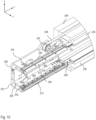
- Fig. 10 shows a perspective detailed view of the area of the left secondary bending beam 205 from Fig. 8 .
- the secondary bending beam 205 has a U-shaped profile which is incorporated into a corresponding U-shaped profile of the extension section 237.
- the secondary bending beam 205 is slidably guided along the guide rails 250 via two upper and two lower guide carriages 249 (see Figs. 11 to 14 ).
- Fig. 10 also shows that two holding devices 213 (an upper and a lower holding device) are provided for the secondary bending beam 205, each of which comprises a front clamping bar 243, via which bending tools are clamped to the secondary bending beam 205.
- the release means 216 which is not visible per se and which opens the corresponding holding device, is shown with dashed lines for both holding devices 213.
- the release means for the upper holding device comprises two contact elements 217 in the form of wedges which are fastened and in particular screwed to the underside of the upper leg of the extension section 237.
- a wedged strip 242 is provided, which is movably arranged between the upper leg of the extension section 237 and the upper leg of the bending beam 205. The wedged strip 242 interacts with the contact elements 217, as will be described further below.
- Corresponding contact elements 217 in the form of wedges are also provided on the upper side of the lower leg of the extension section 237, which in turn interact with a wedged strip 242, which is movably arranged between the lower leg of the extension section 237 and the lower leg of the bending beam 205.
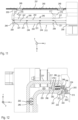
- Figs. 11 and 12 show in detail the structure of the upper holding device 213 and the associated release means 216 of the bending beam 205 in a state in which the bending tool 209 is fixed by the holding device 213.
- Fig. 11 shows a plan view of a plane in which are located the two contact elements 217 and the wedged strip 242 for the upper holding device.
- the secondary bending beam 205 is in a position which is outside of the primary bending beam 234, but does not yet correspond to a release position further to the left in Fig. 11 , in which the holding device 213 is open.
- the wedged strip 242 has two inclined contact surfaces 227 which, in the position shown in Fig.
- Fig. 11 do not yet interact with opposite inclined surfaces of the contact elements 217.
- Fig. 11 shows several fastening means 244 in the form of screws, several elastic means 221 in the form of disc springs, a rear clamping bar 247 and further fastening means 246. These components are described below with reference to Fig. 12 .
- Fig. 12 shows a section in the xz-plane from Fig. 11 at the position of the bending tool 209.
- the fastening means 244 is screwed to a holding means 245 in the form of a cylindrical pin, with the holding means 245 in turn being inserted into a bore in the wedged strip 242 and thereby producing a rigid connection via the further fastening means 246 between the wedged strip 242 and the holding means 245.
- the holding means 245 holds the wedged strip 242 between the upper leg of the extension section 237 and the lower leg of the bending beam 205.
- Fig. 12 shows a section in the xz-plane from Fig. 11 at the position of the bending tool 209.
- the fastening means 244 is screwed to a holding means 245 in the form of a cylindrical pin, with the holding means 245 in turn being inserted into a bore in the wedged strip 242 and thereby producing a rigid connection via the further fastening means 246 between the wedged strip
- the rear clamping bar 247 is located behind the front clamping bar 243 and is firmly connected to the upper leg of the bending beam 205, for example via a screw connection.
- the rear clamping bar 247 has a bore in which there is a socket 248 through which the holding means 248 extends.
- the socket and a section on the back of the rear clamping bar 247 press against the elastic means 221 in the form of disc springs.
- a section of the elastic means 221 is arranged in a receptacle of the clamping bar 242, so that the clamping bar 242 constitutes an abutment for the elastic means 221, which is placed under pretensioning force.
- a positioning means 223 in the form of an adjusting wedge is again provided, which engages in a corresponding recess 225 of the bending tool 209.
- a loss prevention device 222 is provided in the form of a tongue or groove, into which an undercut 224 of the bending tool 209 engages.
- Fig. 13 shows a plan view analogous to Fig. 11
- Fig. 14 shows a section analogous to Fig. 12 .
- the front inclined section of the corresponding contact elements 217 interacts with the opposite inclined contact surfaces 227 of the wedged strip 242.
- the wedged strip 242 slides forward together with the holding means 245 and the front clamping bar 243 (i.e., to the right in the sectional view of Fig.
- the bending tool 209 is still held in the holding device via the loss prevention device 222, but can be removed from the holding device by an operator via a corresponding tilting movement.
- Embodiments of a bending machine have been described above, in which the fixing of the bending tools in a corresponding holding device is ensured via an elastic means and this fixing is released in a purely mechanical manner by generating a corresponding release force. Nevertheless, it is also possible for the bending tools to be fixed in some other way, for example hydraulically, and for the corresponding release force to release the fixing also to be generated hydraulically.
- hydraulic clamping is used in the panel bender described above instead of mechanical clamping, this has the disadvantage that hydraulic hoses, for example via energy chains, must be routed over the entire bending length.
- a hydraulic clamping bar having a closed hydraulic circuit can be used.
- the secondary bending beam has two positions, a parked position and a tool change position. The bending tool is still clamped in the parked position, whereas this clamping is released in the tool change position. In the tool change position, a quick-release coupling of the otherwise self-sufficient hydraulic circuit of the clamp is connected to a controlled circuit and the pressure of the clamp for disengaging or clamping the bending tools is controlled directly.
- a hydraulic pump can also be provided for this.
- the hydraulic pressure in the self-sufficient hydraulic circuit is constant and the bending tools are held in the clamping unit. There is no connection to the controlled hydraulic circuit. If the secondary bending beam is moved to the tool change position, it is coupled to the controllable hydraulic circuit via the quick coupling. The hydraulic pressure in the controlled hydraulic circuit can then be reduced thereby to effect release of the clamp. On the other hand, the pressure for effecting the clamping is increased again. If the secondary bending beam is then moved from the tool change position to the parked position after a tool change, the controllable hydraulic circuit is decoupled again, wherein a non-return valve keeps the pressure within the clamp constant. The clamping is then self-sufficient again.
- an already existing movement of a bending beam in a bending machine is also used in a simple manner to open a holding device to thereby release bending tools fixed in the holding device.
- a release position for the movable bending beam is defined, wherein a movement of the bending beam towards the release position actuates a corresponding release means when the release position is reached, to thereby open the holding device.
- the invention can be used for various types of bending machines. In particular, it can be used both in press brakes for free bending of workpieces, and in panel benders where the workpiece is fixed during the bending process.
Landscapes
- Engineering & Computer Science (AREA)
- Mechanical Engineering (AREA)
- Bending Of Plates, Rods, And Pipes (AREA)
Claims (16)
- Biegemaschine, wobei die Biegemaschine (100; 200) einen Biegebalken (105; 205, 205') aufweist, der mindestens in einer Arbeitsrichtung (z) der Biegemaschine (100; 200) bewegt werden kann, um ein Werkstück durch Biegen entlang einer Biegelinie zu bilden, die in einer Breitenrichtung (y) der Biegemaschine (100; 200) verläuft, wobei die Biegemaschine (100; 200) eine Haltevorrichtung (113; 213), um mindestens ein Biegewerkzeug (109; 209) an der Biegemaschine (100; 200) zu montieren, und Freigabemittel (116, 216) enthält, die an der Biegemaschine (100; 200) bereitgestellt sind, um die Haltevorrichtung (113; 213) aus einer geschlossenen Position, in der das mindestens eine Biegewerkzeug (109; 209) fixiert ist, in eine offene Position zu bewegen, in der das mindestens eine Biegewerkzeug (109; 209) freigegeben ist,
dadurch gekennzeichnet, dass
die Biegemaschine (100; 200) so ausgestaltet, dass eine Bewegung des Biegebalkens (105; 205, 205') in Richtung einer vorgegebenen Freigabeposition die Freigabemittel (116; 216) betätigt, wenn die vorgegebene Freigabeposition erreicht ist. - Biegemaschine nach Anspruch 1, dadurch gekennzeichnet, dass die Haltevorrichtung (113; 213) ausgestaltet ist, um das mindestens eine Biegewerkzeug (109; 209) in einer positiven und/oder nicht positiven Weise zu fixieren.
- Biegemaschine nach Anspruch 1 oder 2, dadurch gekennzeichnet, dass die Biegemaschine (100; 200) so ausgestaltet ist, dass die Bewegung des Biegebalkens (105; 205, 205'), Wenn die vorgegebene Freigabeposition erreicht ist, eine Freigabekraft erzeugt, die mittels der Freigabemittel (116; 216) auf die Haltevorrichtung (113; 213) ausgeübt wird, um das Fixieren des mindestens einen Biegewerkzeugs (109; 209) aufzuheben.
- Biegemaschine nach einem der vorhergehenden Ansprüche, dadurch gekennzeichnet, dass die Biegemaschine (100; 200) so ausgestaltet ist, dass die Bewegung des Biegebalkens (105; 205, 205') in Richtung der vorgegebenen Freigabeposition eine Bewegung in Arbeitsrichtung (z) oder in eine von der Arbeitsrichtung (z) abweichenden Richtung einbezieht, wobei die abweichende Richtung vorzugsweise der Breitenrichtung (y) der Biegemaschine (100; 200) entspricht.
- Biegemaschine nach einem der vorhergehenden Ansprüche, dadurch gekennzeichnet, dass die Freigabemittel (116; 216) unbeweglich an der Biegemaschine (100; 200) angebracht sind, während die Haltevorrichtung (113; 213) zusammen mit dem Biegebalken (105; 205, 205') in Richtung der vorgegebenen Freigabeposition bewegt werden kann, wobei die Haltevorrichtung (113; 213) vorzugsweise an dem Biegebalken (105; 205, 205') bereitgestellt ist, um das mindestens eine Biegewerkzeug (109; 209) an dem Biegebalken (105; 205, 205') zu halten.
- Biegemaschine nach einem der vorhergehenden Ansprüche, dadurch gekennzeichnet, dass die Freigabemittel (116; 216) ein oder mehrere Berührungselemente (117; 217), vorzugsweise einen oder mehrere Keile, enthält, die derart angeordnet sind, dass sie die Haltevorrichtung (113; 213) freigeben, wenn die vorgegebene Freigabeposition mechanisch berührt wird, und dadurch das Fixieren des mindestens einen Biegewerkzeugs (109; 209) aufheben.
- Biegemaschine nach Anspruch 6, dadurch gekennzeichnet, dass ein jeweiliges Berührungselement (117; 217) so ausgestaltet ist, dass es bei Erreichen der vorgegebenen Freigabeposition gegen mindestens eine Berührungsoberfläche (127; 227) der Haltevorrichtung (113; 213) drückt und dadurch eine Bewegung der Haltevorrichtung (113; 213) auslöst, wodurch das Fixieren des mindestens einen Biegewerkzeugs (109; 209) aufgehoben wird.
- Biegemaschine nach einem der vorhergehenden Ansprüche, dadurch gekennzeichnet, dass die Haltevorrichtung (113; 213) eine Klemmvorrichtung ist, die so ausgestaltet ist, dass sie zum Fixieren des mindestens einen Biegewerkzeugs (109; 209) eine Haltekraft in Form einer Klemmkraft auf das mindestens eine Biegewerkzeug (109; 209) ausübt.
- Biegemaschine nach einem der vorhergehenden Ansprüche, dadurch gekennzeichnet, dass die Haltevorrichtung (113; 213) ein oder mehrere elastische Mittel (121; 221) umfasst, die in der Haltevorrichtung (113; 213) vorgespannt sind, um dadurch eine Haltekraft zum Fixieren des mindestens einen Biegewerkzeugs (109; 209) zu erzeugen.
- Biegemaschine nach einem der vorhergehenden Ansprüche, dadurch gekennzeichnet, dass die Haltevorrichtung (113; 213) eine oder mehrere Verliersicherungsvorrichtungen (122; 222), um das mindestens eine Biegewerkzeug (109; 209) lose in der Haltevorrichtung (113; 213) zu halten, wenn die Haltevorrichtung (113; 213) geöffnet ist, und/oder ein oder mehrere Positioniermittel (123; 223) umfasst, um sicherzustellen, dass, wenn die vorgegebene Freigabeposition erreicht ist, sich das mindestens eine Biegewerkzeug (109; 209) in eine vorgegebene Position bewegt, in der das mindestens eine Biegewerkzeug (109; 209) durch die Haltevorrichtung (113; 213) gehalten wird.
- Biegemaschine nach einem der vorhergehenden Ansprüche, dadurch gekennzeichnet, dass in der Biegemaschine (100; 200) ein Sensorsystem (108) bereitgestellt ist, das konfiguriert ist, um eine Annäherung des Biegebalkens (105; 205, 205') in Richtung der vorgegebenen Freigabeposition als Erkennungsereignis zu erkennen, wobei die Biegemaschine (100; 200) vorzugsweise so konfiguriert ist, dass, wenn das Erkennungsereignis erkannt wird, eine Nachricht über eine Benutzerschnittstelle (111) der Biegemaschine (100; 200) ausgegeben wird.
- Biegemaschine nach einem der vorhergehenden Ansprüche, dadurch gekennzeichnet, dass die Freigabemittel (116; 216) in eine Parkposition an der Biegemaschine bewegt werden können, in der die Freigabemittel (116; 216) nicht durch Bewegen des Biegebalkens (105; 205, 205') bewegt werden können.
- Biegemaschine nach einem der vorhergehenden Ansprüche, dadurch gekennzeichnet, dass die Biegemaschine (100; 200) eine Abkantpresse (100) zum freien Biegen eines Werkstücks zwischen einem beweglichen Oberbalken (105) und einem stationären Unterbalken (106) ist, wobei der Biegebalken (105; 205, 205') der Oberbalken (105) ist.
- Biegemaschine nach Anspruch 13, dadurch gekennzeichnet, dass die Haltevorrichtung (113; 213) an dem Oberbalken (105) bereitgestellt ist, um das mindestens eine Biegewerkzeug (109; 209) an dem Oberbalken (105) zu halten, und die Freigabemittel (116; 216) Angeordnet sind, um dem Oberbalken (105) benachbart unbeweglich zu sein, wobei die vorgegebene Freigabeposition durch die Bewegung des Oberbalkens (105) in der Arbeitsrichtung (z) weg von dem Unterbalken (106) erreicht wird.
- Biegemaschine nach einem der Ansprüche 1 bis 12, dadurch gekennzeichnet, dass die Biegemaschine (100; 200) eine Blechbiegemaschine (200) ist, die so konfiguriert ist, dass das Werkstück während des Biegens fixiert ist.
- Biegemaschine nach Anspruch 15, dadurch gekennzeichnet, dass die Haltevorrichtung (113; 213) an dem Biegebalken (105; 205, 205') bereitgestellt ist, um das mindestens eine Biegewerkzeug (109; 209) an dem Biegebalken (105; 205, 205') zu halten, und die vorgegebene Freigabeposition sich außerhalb eines Arbeitsbereichs befindet, in dem das Biegen durch den Biegebalken (105; 205, 205') stattfindet, wobei der Biegebalken (113; 213) in der vorgegebenen Freigabeposition vorzugsweise in der Breitenrichtung (y) der Blechbiegemaschine (200) bewegbar ist.
Applications Claiming Priority (2)
| Application Number | Priority Date | Filing Date | Title |
|---|---|---|---|
| EP21208406.5A EP4180140A1 (de) | 2021-11-16 | 2021-11-16 | Biegemaschine |
| PCT/EP2022/081558 WO2023088790A1 (en) | 2021-11-16 | 2022-11-10 | Bending machine |
Publications (2)
| Publication Number | Publication Date |
|---|---|
| EP4433236A1 EP4433236A1 (de) | 2024-09-25 |
| EP4433236B1 true EP4433236B1 (de) | 2025-03-05 |
Family
ID=78649236
Family Applications (2)
| Application Number | Title | Priority Date | Filing Date |
|---|---|---|---|
| EP21208406.5A Withdrawn EP4180140A1 (de) | 2021-11-16 | 2021-11-16 | Biegemaschine |
| EP22817898.4A Active EP4433236B1 (de) | 2021-11-16 | 2022-11-10 | Biegemaschine |
Family Applications Before (1)
| Application Number | Title | Priority Date | Filing Date |
|---|---|---|---|
| EP21208406.5A Withdrawn EP4180140A1 (de) | 2021-11-16 | 2021-11-16 | Biegemaschine |
Country Status (3)
| Country | Link |
|---|---|
| EP (2) | EP4180140A1 (de) |
| CN (1) | CN118234576B (de) |
| WO (1) | WO2023088790A1 (de) |
Family Cites Families (12)
| Publication number | Priority date | Publication date | Assignee | Title |
|---|---|---|---|---|
| AT364589B (de) | 1979-08-01 | 1981-10-27 | Haemmerle Ag | Spannvorrichtung zur befestigung eines werkzeuges an einem werkzeughalter |
| JPS57199523A (en) * | 1982-05-28 | 1982-12-07 | Hitachi Ltd | Bending die holding device |
| DE19513576C2 (de) | 1995-04-19 | 1997-04-30 | Guenzburger Werkzeugmaschinenf | Werkzeugträger für eine Biegepresse |
| US5927134A (en) * | 1996-08-30 | 1999-07-27 | Reinhardt Maschinenbau Gmbh | Bending machine |
| AT408729B (de) * | 2000-08-14 | 2002-02-25 | Trumpf Maschinen Austria Gmbh | Werkzeugspannvorrichtung für ein formwerkzeug, insbesondere einer abkantpresse |
| PL1862233T3 (pl) * | 2006-06-01 | 2011-07-29 | Wila Bv | Narzędzie z automatycznym zatrzaskiem zabezpieczającym |
| ES2892223T3 (es) * | 2008-11-11 | 2022-02-02 | Wila Bv | Dispositivo para sujetar una herramienta |
| JP6364497B2 (ja) * | 2014-02-10 | 2018-07-25 | サルヴァニーニ イタリア エッセ.ピ.ア.SALVAGNINI ITALIA S.p.A. | 板金用の曲げ機械 |
| US9555456B2 (en) | 2014-04-26 | 2017-01-31 | Wilson Tool International Inc. | Dynamic clamp and tool holders therefor |
| IT201700052500A1 (it) * | 2017-05-15 | 2018-11-15 | Salvagnini Italia Spa | Macchina piegatrice per lamiere metalliche |
| AT520943B1 (de) * | 2018-02-21 | 2019-09-15 | Trumpf Maschinen Austria Gmbh & Co Kg | Fertigungsanlage mit Werkzeugwechseleinheit und Klemmbacke sowie Verfahren zum Werkzeugwechsel |
| IT201900006656A1 (it) * | 2019-05-08 | 2020-11-08 | Salvagnini Italia Spa | Macchina piegatrice per lamiere metalliche |
-
2021
- 2021-11-16 EP EP21208406.5A patent/EP4180140A1/de not_active Withdrawn
-
2022
- 2022-11-10 CN CN202280075730.0A patent/CN118234576B/zh active Active
- 2022-11-10 WO PCT/EP2022/081558 patent/WO2023088790A1/en not_active Ceased
- 2022-11-10 EP EP22817898.4A patent/EP4433236B1/de active Active
Also Published As
| Publication number | Publication date |
|---|---|
| WO2023088790A1 (en) | 2023-05-25 |
| EP4433236A1 (de) | 2024-09-25 |
| EP4180140A1 (de) | 2023-05-17 |
| CN118234576A (zh) | 2024-06-21 |
| CN118234576B (zh) | 2024-12-31 |
Similar Documents
| Publication | Publication Date | Title |
|---|---|---|
| US10537925B2 (en) | Sheet metal bending machine | |
| US5794486A (en) | Upper tool holder apparatus for press brake | |
| US5442843A (en) | Drilling machine for drilling holes in furniture parts | |
| CA2459966C (en) | Combination of a press brake clamping system and at least a press brake tool | |
| US20140283576A1 (en) | Sheet material processing apparatus, press die, and die setting body | |
| US10987715B2 (en) | Tool storage system, production plant and method for manipulating with such a tool storage system | |
| JP5054681B2 (ja) | 楔形ドライブ用工具ファスニングデバイス | |
| EP3825028B1 (de) | Oberwerkzeugspeicher | |
| EP0644002B1 (de) | Oberes Werkzeug für Biegepresse | |
| JP2008546538A5 (de) | ||
| EP2736673B1 (de) | Vorrichtung und verfahren zur installation von bandbefestigungen auf förderbändern | |
| KR100546022B1 (ko) | 상형 홀더 장치 | |
| CN113795340A (zh) | 金属板折弯机 | |
| EP4433236B1 (de) | Biegemaschine | |
| US7784317B2 (en) | Safety system for a bending press and a slatted tool | |
| CN111971132B (zh) | 具有工具更换单元和夹爪的生产设备以及更换工具的方法 | |
| US6178799B1 (en) | Forming press and method for shaping angle-section workpieces | |
| EP1117505B1 (de) | Multifunktionspresse für einsatzstücke | |
| EP1366832B1 (de) | Werkzeugkupplungsvorrichtung, insbesondere für Pressen | |
| WO2024018428A1 (en) | Device for locking tools for a press brake | |
| GB2077173A (en) | Improvements in and relating to punching machines | |
| EP0796679A1 (de) | Blechbearbeitungsmaschine | |
| CA2123844A1 (en) | Upper tool for press brake | |
| CN112756472A (zh) | 一种自动清理废料的球面双向冲孔模 | |
| JPH0588716U (ja) | 縦型パンチングマシン |
Legal Events
| Date | Code | Title | Description |
|---|---|---|---|
| STAA | Information on the status of an ep patent application or granted ep patent |
Free format text: STATUS: UNKNOWN |
|
| STAA | Information on the status of an ep patent application or granted ep patent |
Free format text: STATUS: THE INTERNATIONAL PUBLICATION HAS BEEN MADE |
|
| PUAI | Public reference made under article 153(3) epc to a published international application that has entered the european phase |
Free format text: ORIGINAL CODE: 0009012 |
|
| STAA | Information on the status of an ep patent application or granted ep patent |
Free format text: STATUS: REQUEST FOR EXAMINATION WAS MADE |
|
| 17P | Request for examination filed |
Effective date: 20240328 |
|
| AK | Designated contracting states |
Kind code of ref document: A1 Designated state(s): AL AT BE BG CH CY CZ DE DK EE ES FI FR GB GR HR HU IE IS IT LI LT LU LV MC ME MK MT NL NO PL PT RO RS SE SI SK SM TR |
|
| GRAP | Despatch of communication of intention to grant a patent |
Free format text: ORIGINAL CODE: EPIDOSNIGR1 |
|
| STAA | Information on the status of an ep patent application or granted ep patent |
Free format text: STATUS: GRANT OF PATENT IS INTENDED |
|
| INTG | Intention to grant announced |
Effective date: 20241024 |
|
| GRAS | Grant fee paid |
Free format text: ORIGINAL CODE: EPIDOSNIGR3 |
|
| GRAA | (expected) grant |
Free format text: ORIGINAL CODE: 0009210 |
|
| STAA | Information on the status of an ep patent application or granted ep patent |
Free format text: STATUS: THE PATENT HAS BEEN GRANTED |
|
| DAV | Request for validation of the european patent (deleted) | ||
| DAX | Request for extension of the european patent (deleted) | ||
| AK | Designated contracting states |
Kind code of ref document: B1 Designated state(s): AL AT BE BG CH CY CZ DE DK EE ES FI FR GB GR HR HU IE IS IT LI LT LU LV MC ME MK MT NL NO PL PT RO RS SE SI SK SM TR |
|
| REG | Reference to a national code |
Ref country code: GB Ref legal event code: FG4D |
|
| REG | Reference to a national code |
Ref country code: CH Ref legal event code: EP |
|
| P01 | Opt-out of the competence of the unified patent court (upc) registered |
Free format text: CASE NUMBER: APP_7290/2025 Effective date: 20250212 |
|
| REG | Reference to a national code |
Ref country code: IE Ref legal event code: FG4D |
|
| REG | Reference to a national code |
Ref country code: DE Ref legal event code: R096 Ref document number: 602022011533 Country of ref document: DE |
|
| PG25 | Lapsed in a contracting state [announced via postgrant information from national office to epo] |
Ref country code: RS Free format text: LAPSE BECAUSE OF FAILURE TO SUBMIT A TRANSLATION OF THE DESCRIPTION OR TO PAY THE FEE WITHIN THE PRESCRIBED TIME-LIMIT Effective date: 20250605 |
|
| PG25 | Lapsed in a contracting state [announced via postgrant information from national office to epo] |
Ref country code: FI Free format text: LAPSE BECAUSE OF FAILURE TO SUBMIT A TRANSLATION OF THE DESCRIPTION OR TO PAY THE FEE WITHIN THE PRESCRIBED TIME-LIMIT Effective date: 20250305 |
|
| REG | Reference to a national code |
Ref country code: NL Ref legal event code: MP Effective date: 20250305 |
|
| PG25 | Lapsed in a contracting state [announced via postgrant information from national office to epo] |
Ref country code: ES Free format text: LAPSE BECAUSE OF FAILURE TO SUBMIT A TRANSLATION OF THE DESCRIPTION OR TO PAY THE FEE WITHIN THE PRESCRIBED TIME-LIMIT Effective date: 20250305 |
|
| REG | Reference to a national code |
Ref country code: LT Ref legal event code: MG9D |
|
| PG25 | Lapsed in a contracting state [announced via postgrant information from national office to epo] |
Ref country code: NO Free format text: LAPSE BECAUSE OF FAILURE TO SUBMIT A TRANSLATION OF THE DESCRIPTION OR TO PAY THE FEE WITHIN THE PRESCRIBED TIME-LIMIT Effective date: 20250605 |
|
| PG25 | Lapsed in a contracting state [announced via postgrant information from national office to epo] |
Ref country code: HR Free format text: LAPSE BECAUSE OF FAILURE TO SUBMIT A TRANSLATION OF THE DESCRIPTION OR TO PAY THE FEE WITHIN THE PRESCRIBED TIME-LIMIT Effective date: 20250305 |
|
| PG25 | Lapsed in a contracting state [announced via postgrant information from national office to epo] |
Ref country code: LV Free format text: LAPSE BECAUSE OF FAILURE TO SUBMIT A TRANSLATION OF THE DESCRIPTION OR TO PAY THE FEE WITHIN THE PRESCRIBED TIME-LIMIT Effective date: 20250305 |
|
| PG25 | Lapsed in a contracting state [announced via postgrant information from national office to epo] |
Ref country code: GR Free format text: LAPSE BECAUSE OF FAILURE TO SUBMIT A TRANSLATION OF THE DESCRIPTION OR TO PAY THE FEE WITHIN THE PRESCRIBED TIME-LIMIT Effective date: 20250606 Ref country code: BG Free format text: LAPSE BECAUSE OF FAILURE TO SUBMIT A TRANSLATION OF THE DESCRIPTION OR TO PAY THE FEE WITHIN THE PRESCRIBED TIME-LIMIT Effective date: 20250305 |
|
| PG25 | Lapsed in a contracting state [announced via postgrant information from national office to epo] |
Ref country code: NL Free format text: LAPSE BECAUSE OF FAILURE TO SUBMIT A TRANSLATION OF THE DESCRIPTION OR TO PAY THE FEE WITHIN THE PRESCRIBED TIME-LIMIT Effective date: 20250305 |
|
| PG25 | Lapsed in a contracting state [announced via postgrant information from national office to epo] |
Ref country code: SE Free format text: LAPSE BECAUSE OF FAILURE TO SUBMIT A TRANSLATION OF THE DESCRIPTION OR TO PAY THE FEE WITHIN THE PRESCRIBED TIME-LIMIT Effective date: 20250305 |
|
| PG25 | Lapsed in a contracting state [announced via postgrant information from national office to epo] |
Ref country code: SM Free format text: LAPSE BECAUSE OF FAILURE TO SUBMIT A TRANSLATION OF THE DESCRIPTION OR TO PAY THE FEE WITHIN THE PRESCRIBED TIME-LIMIT Effective date: 20250305 |
|
| PG25 | Lapsed in a contracting state [announced via postgrant information from national office to epo] |
Ref country code: PT Free format text: LAPSE BECAUSE OF FAILURE TO SUBMIT A TRANSLATION OF THE DESCRIPTION OR TO PAY THE FEE WITHIN THE PRESCRIBED TIME-LIMIT Effective date: 20250707 |
|
| PG25 | Lapsed in a contracting state [announced via postgrant information from national office to epo] |
Ref country code: PL Free format text: LAPSE BECAUSE OF FAILURE TO SUBMIT A TRANSLATION OF THE DESCRIPTION OR TO PAY THE FEE WITHIN THE PRESCRIBED TIME-LIMIT Effective date: 20250305 |
|
| PG25 | Lapsed in a contracting state [announced via postgrant information from national office to epo] |
Ref country code: AT Free format text: LAPSE BECAUSE OF FAILURE TO SUBMIT A TRANSLATION OF THE DESCRIPTION OR TO PAY THE FEE WITHIN THE PRESCRIBED TIME-LIMIT Effective date: 20250305 |
|
| PG25 | Lapsed in a contracting state [announced via postgrant information from national office to epo] |
Ref country code: CZ Free format text: LAPSE BECAUSE OF FAILURE TO SUBMIT A TRANSLATION OF THE DESCRIPTION OR TO PAY THE FEE WITHIN THE PRESCRIBED TIME-LIMIT Effective date: 20250305 Ref country code: EE Free format text: LAPSE BECAUSE OF FAILURE TO SUBMIT A TRANSLATION OF THE DESCRIPTION OR TO PAY THE FEE WITHIN THE PRESCRIBED TIME-LIMIT Effective date: 20250305 |
|
| PG25 | Lapsed in a contracting state [announced via postgrant information from national office to epo] |
Ref country code: SK Free format text: LAPSE BECAUSE OF FAILURE TO SUBMIT A TRANSLATION OF THE DESCRIPTION OR TO PAY THE FEE WITHIN THE PRESCRIBED TIME-LIMIT Effective date: 20250305 |
|
| PG25 | Lapsed in a contracting state [announced via postgrant information from national office to epo] |
Ref country code: IS Free format text: LAPSE BECAUSE OF FAILURE TO SUBMIT A TRANSLATION OF THE DESCRIPTION OR TO PAY THE FEE WITHIN THE PRESCRIBED TIME-LIMIT Effective date: 20250705 |
|
| REG | Reference to a national code |
Ref country code: CH Ref legal event code: U11 Free format text: ST27 STATUS EVENT CODE: U-0-0-U10-U11 (AS PROVIDED BY THE NATIONAL OFFICE) Effective date: 20251201 |