EP4432002A2 - Augenvorrichtungsgehäuse und nachfüllbehälter für das augenvorrichtungsgehäuse - Google Patents
Augenvorrichtungsgehäuse und nachfüllbehälter für das augenvorrichtungsgehäuse Download PDFInfo
- Publication number
- EP4432002A2 EP4432002A2 EP24192001.6A EP24192001A EP4432002A2 EP 4432002 A2 EP4432002 A2 EP 4432002A2 EP 24192001 A EP24192001 A EP 24192001A EP 4432002 A2 EP4432002 A2 EP 4432002A2
- Authority
- EP
- European Patent Office
- Prior art keywords
- treatment liquid
- ocular device
- spout
- storage area
- refill container
- Prior art date
- Legal status (The legal status is an assumption and is not a legal conclusion. Google has not performed a legal analysis and makes no representation as to the accuracy of the status listed.)
- Pending
Links
- 239000007788 liquid Substances 0.000 claims abstract description 236
- 238000011282 treatment Methods 0.000 claims abstract description 233
- 238000003860 storage Methods 0.000 claims description 107
- 230000002093 peripheral effect Effects 0.000 claims description 76
- 238000003780 insertion Methods 0.000 claims description 66
- 230000037431 insertion Effects 0.000 claims description 66
- MHAJPDPJQMAIIY-UHFFFAOYSA-N Hydrogen peroxide Chemical compound OO MHAJPDPJQMAIIY-UHFFFAOYSA-N 0.000 claims description 24
- WQYVRQLZKVEZGA-UHFFFAOYSA-N hypochlorite Chemical compound Cl[O-] WQYVRQLZKVEZGA-UHFFFAOYSA-N 0.000 claims description 8
- 238000004140 cleaning Methods 0.000 claims description 7
- KFSLWBXXFJQRDL-UHFFFAOYSA-N Peracetic acid Chemical compound CC(=O)OO KFSLWBXXFJQRDL-UHFFFAOYSA-N 0.000 claims description 6
- OSVXSBDYLRYLIG-UHFFFAOYSA-N dioxidochlorine(.) Chemical compound O=Cl=O OSVXSBDYLRYLIG-UHFFFAOYSA-N 0.000 claims description 6
- 150000003839 salts Chemical class 0.000 claims description 6
- CPKVUHPKYQGHMW-UHFFFAOYSA-N 1-ethenylpyrrolidin-2-one;molecular iodine Chemical compound II.C=CN1CCCC1=O CPKVUHPKYQGHMW-UHFFFAOYSA-N 0.000 claims description 5
- 229920000153 Povidone-iodine Polymers 0.000 claims description 5
- 239000003795 chemical substances by application Substances 0.000 claims description 5
- 229960001621 povidone-iodine Drugs 0.000 claims description 5
- 239000005871 repellent Substances 0.000 claims description 5
- LJGHYPLBDBRCRZ-UHFFFAOYSA-N 3-(3-aminophenyl)sulfonylaniline Chemical compound NC1=CC=CC(S(=O)(=O)C=2C=C(N)C=CC=2)=C1 LJGHYPLBDBRCRZ-UHFFFAOYSA-N 0.000 claims description 3
- ZAMOUSCENKQFHK-UHFFFAOYSA-N Chlorine atom Chemical compound [Cl] ZAMOUSCENKQFHK-UHFFFAOYSA-N 0.000 claims description 3
- 239000004155 Chlorine dioxide Substances 0.000 claims description 3
- 239000000460 chlorine Substances 0.000 claims description 3
- 229910052801 chlorine Inorganic materials 0.000 claims description 3
- 235000019398 chlorine dioxide Nutrition 0.000 claims description 3
- 229910001919 chlorite Inorganic materials 0.000 claims description 3
- 229910052619 chlorite group Inorganic materials 0.000 claims description 3
- QBWCMBCROVPCKQ-UHFFFAOYSA-N chlorous acid Chemical compound OCl=O QBWCMBCROVPCKQ-UHFFFAOYSA-N 0.000 claims description 3
- 239000006260 foam Substances 0.000 claims description 3
- PEYVWSJAZONVQK-UHFFFAOYSA-N hydroperoxy(oxo)borane Chemical compound OOB=O PEYVWSJAZONVQK-UHFFFAOYSA-N 0.000 claims description 3
- 230000005661 hydrophobic surface Effects 0.000 claims description 3
- 150000002978 peroxides Chemical class 0.000 claims description 3
- 230000000249 desinfective effect Effects 0.000 claims description 2
- 230000000694 effects Effects 0.000 abstract description 6
- 230000002411 adverse Effects 0.000 abstract description 4
- 238000012856 packing Methods 0.000 description 34
- 238000002347 injection Methods 0.000 description 16
- 239000007924 injection Substances 0.000 description 16
- 238000004659 sterilization and disinfection Methods 0.000 description 15
- 239000003054 catalyst Substances 0.000 description 13
- 230000001954 sterilising effect Effects 0.000 description 11
- 230000009471 action Effects 0.000 description 8
- 238000000354 decomposition reaction Methods 0.000 description 8
- 229920005989 resin Polymers 0.000 description 7
- 239000011347 resin Substances 0.000 description 7
- 238000003825 pressing Methods 0.000 description 6
- 238000004891 communication Methods 0.000 description 5
- 238000005187 foaming Methods 0.000 description 5
- 239000013078 crystal Substances 0.000 description 4
- 230000005489 elastic deformation Effects 0.000 description 4
- 239000007789 gas Substances 0.000 description 4
- QOSATHPSBFQAML-UHFFFAOYSA-N hydrogen peroxide;hydrate Chemical compound O.OO QOSATHPSBFQAML-UHFFFAOYSA-N 0.000 description 4
- 238000000034 method Methods 0.000 description 4
- 238000012545 processing Methods 0.000 description 4
- 230000002829 reductive effect Effects 0.000 description 4
- XLYOFNOQVPJJNP-UHFFFAOYSA-N water Substances O XLYOFNOQVPJJNP-UHFFFAOYSA-N 0.000 description 4
- 238000003466 welding Methods 0.000 description 4
- 229920001971 elastomer Polymers 0.000 description 3
- 230000004438 eyesight Effects 0.000 description 3
- 239000000463 material Substances 0.000 description 3
- 230000004379 myopia Effects 0.000 description 3
- 208000001491 myopia Diseases 0.000 description 3
- 230000003287 optical effect Effects 0.000 description 3
- 230000008569 process Effects 0.000 description 3
- CIWBSHSKHKDKBQ-JLAZNSOCSA-N Ascorbic acid Chemical compound OC[C@H](O)[C@H]1OC(=O)C(O)=C1O CIWBSHSKHKDKBQ-JLAZNSOCSA-N 0.000 description 2
- MYMOFIZGZYHOMD-UHFFFAOYSA-N Dioxygen Chemical compound O=O MYMOFIZGZYHOMD-UHFFFAOYSA-N 0.000 description 2
- 206010020675 Hypermetropia Diseases 0.000 description 2
- 244000052616 bacterial pathogen Species 0.000 description 2
- 238000012937 correction Methods 0.000 description 2
- 239000002537 cosmetic Substances 0.000 description 2
- 239000000645 desinfectant Substances 0.000 description 2
- 229910001882 dioxygen Inorganic materials 0.000 description 2
- 239000000806 elastomer Substances 0.000 description 2
- 230000002209 hydrophobic effect Effects 0.000 description 2
- 201000006318 hyperopia Diseases 0.000 description 2
- 230000004305 hyperopia Effects 0.000 description 2
- 230000000149 penetrating effect Effects 0.000 description 2
- BASFCYQUMIYNBI-UHFFFAOYSA-N platinum Chemical compound [Pt] BASFCYQUMIYNBI-UHFFFAOYSA-N 0.000 description 2
- -1 polyethylene terephthalate Polymers 0.000 description 2
- 229920000642 polymer Polymers 0.000 description 2
- 229920001296 polysiloxane Polymers 0.000 description 2
- 201000010041 presbyopia Diseases 0.000 description 2
- 239000003755 preservative agent Substances 0.000 description 2
- 230000002335 preservative effect Effects 0.000 description 2
- GEHJYWRUCIMESM-UHFFFAOYSA-L sodium sulfite Chemical compound [Na+].[Na+].[O-]S([O-])=O GEHJYWRUCIMESM-UHFFFAOYSA-L 0.000 description 2
- 239000000243 solution Substances 0.000 description 2
- 230000001629 suppression Effects 0.000 description 2
- 102000016938 Catalase Human genes 0.000 description 1
- 108010053835 Catalase Proteins 0.000 description 1
- 102000004190 Enzymes Human genes 0.000 description 1
- 108090000790 Enzymes Proteins 0.000 description 1
- 206010015946 Eye irritation Diseases 0.000 description 1
- YCKRFDGAMUMZLT-UHFFFAOYSA-N Fluorine atom Chemical compound [F] YCKRFDGAMUMZLT-UHFFFAOYSA-N 0.000 description 1
- 206010020751 Hypersensitivity Diseases 0.000 description 1
- 239000004743 Polypropylene Substances 0.000 description 1
- 239000004793 Polystyrene Substances 0.000 description 1
- 229920000122 acrylonitrile butadiene styrene Polymers 0.000 description 1
- 239000004676 acrylonitrile butadiene styrene Substances 0.000 description 1
- 230000000172 allergic effect Effects 0.000 description 1
- 208000030961 allergic reaction Diseases 0.000 description 1
- 230000000844 anti-bacterial effect Effects 0.000 description 1
- 235000010323 ascorbic acid Nutrition 0.000 description 1
- 229960005070 ascorbic acid Drugs 0.000 description 1
- 239000011668 ascorbic acid Substances 0.000 description 1
- 201000009310 astigmatism Diseases 0.000 description 1
- 208000010668 atopic eczema Diseases 0.000 description 1
- 230000003796 beauty Effects 0.000 description 1
- 230000008901 benefit Effects 0.000 description 1
- 239000000090 biomarker Substances 0.000 description 1
- 230000003197 catalytic effect Effects 0.000 description 1
- 230000008859 change Effects 0.000 description 1
- 239000011248 coating agent Substances 0.000 description 1
- 238000000576 coating method Methods 0.000 description 1
- 238000004040 coloring Methods 0.000 description 1
- 230000006835 compression Effects 0.000 description 1
- 238000007906 compression Methods 0.000 description 1
- 210000004087 cornea Anatomy 0.000 description 1
- 208000021921 corneal disease Diseases 0.000 description 1
- 238000005520 cutting process Methods 0.000 description 1
- 230000007423 decrease Effects 0.000 description 1
- 230000003247 decreasing effect Effects 0.000 description 1
- 238000013461 design Methods 0.000 description 1
- 230000010339 dilation Effects 0.000 description 1
- 238000009826 distribution Methods 0.000 description 1
- 239000003814 drug Substances 0.000 description 1
- 229940079593 drug Drugs 0.000 description 1
- 238000001035 drying Methods 0.000 description 1
- 231100000013 eye irritation Toxicity 0.000 description 1
- 238000011049 filling Methods 0.000 description 1
- 239000010408 film Substances 0.000 description 1
- 229910052731 fluorine Inorganic materials 0.000 description 1
- 239000011737 fluorine Substances 0.000 description 1
- 229920001600 hydrophobic polymer Polymers 0.000 description 1
- 238000003384 imaging method Methods 0.000 description 1
- 230000000977 initiatory effect Effects 0.000 description 1
- 230000002452 interceptive effect Effects 0.000 description 1
- 230000009545 invasion Effects 0.000 description 1
- 239000002085 irritant Substances 0.000 description 1
- 231100000021 irritant Toxicity 0.000 description 1
- 230000007794 irritation Effects 0.000 description 1
- 230000009191 jumping Effects 0.000 description 1
- 238000004519 manufacturing process Methods 0.000 description 1
- 230000003472 neutralizing effect Effects 0.000 description 1
- 229910052697 platinum Inorganic materials 0.000 description 1
- 229920000139 polyethylene terephthalate Polymers 0.000 description 1
- 239000005020 polyethylene terephthalate Substances 0.000 description 1
- 229920001155 polypropylene Polymers 0.000 description 1
- 229920002223 polystyrene Polymers 0.000 description 1
- 230000004515 progressive myopia Effects 0.000 description 1
- 230000004044 response Effects 0.000 description 1
- 210000001525 retina Anatomy 0.000 description 1
- 239000012487 rinsing solution Substances 0.000 description 1
- 238000007789 sealing Methods 0.000 description 1
- 235000010265 sodium sulphite Nutrition 0.000 description 1
- 239000002904 solvent Substances 0.000 description 1
- 238000003892 spreading Methods 0.000 description 1
- 230000007480 spreading Effects 0.000 description 1
- 238000003756 stirring Methods 0.000 description 1
- 239000000758 substrate Substances 0.000 description 1
- 238000004381 surface treatment Methods 0.000 description 1
- 229920003002 synthetic resin Polymers 0.000 description 1
- 239000000057 synthetic resin Substances 0.000 description 1
- 238000002560 therapeutic procedure Methods 0.000 description 1
- 239000010409 thin film Substances 0.000 description 1
- 238000012546 transfer Methods 0.000 description 1
- 230000000007 visual effect Effects 0.000 description 1
Images


Classifications
-
- A—HUMAN NECESSITIES
- A61—MEDICAL OR VETERINARY SCIENCE; HYGIENE
- A61L—METHODS OR APPARATUS FOR STERILISING MATERIALS OR OBJECTS IN GENERAL; DISINFECTION, STERILISATION OR DEODORISATION OF AIR; CHEMICAL ASPECTS OF BANDAGES, DRESSINGS, ABSORBENT PADS OR SURGICAL ARTICLES; MATERIALS FOR BANDAGES, DRESSINGS, ABSORBENT PADS OR SURGICAL ARTICLES
- A61L12/00—Methods or apparatus for disinfecting or sterilising contact lenses; Accessories therefor
- A61L12/08—Methods or apparatus for disinfecting or sterilising contact lenses; Accessories therefor using chemical substances
- A61L12/086—Container, accessories or devices therefor
-
- A—HUMAN NECESSITIES
- A45—HAND OR TRAVELLING ARTICLES
- A45C—PURSES; LUGGAGE; HAND CARRIED BAGS
- A45C11/00—Receptacles for purposes not provided for in groups A45C1/00-A45C9/00
- A45C11/005—Contact lens cases
-
- A—HUMAN NECESSITIES
- A45—HAND OR TRAVELLING ARTICLES
- A45D—HAIRDRESSING OR SHAVING EQUIPMENT; EQUIPMENT FOR COSMETICS OR COSMETIC TREATMENTS, e.g. FOR MANICURING OR PEDICURING
- A45D34/00—Containers or accessories specially adapted for handling liquid toiletry or cosmetic substances, e.g. perfumes
-
- G—PHYSICS
- G02—OPTICS
- G02C—SPECTACLES; SUNGLASSES OR GOGGLES INSOFAR AS THEY HAVE THE SAME FEATURES AS SPECTACLES; CONTACT LENSES
- G02C13/00—Assembling; Repairing; Cleaning
- G02C13/008—Devices specially adapted for cleaning contact lenses
-
- A—HUMAN NECESSITIES
- A61—MEDICAL OR VETERINARY SCIENCE; HYGIENE
- A61L—METHODS OR APPARATUS FOR STERILISING MATERIALS OR OBJECTS IN GENERAL; DISINFECTION, STERILISATION OR DEODORISATION OF AIR; CHEMICAL ASPECTS OF BANDAGES, DRESSINGS, ABSORBENT PADS OR SURGICAL ARTICLES; MATERIALS FOR BANDAGES, DRESSINGS, ABSORBENT PADS OR SURGICAL ARTICLES
- A61L12/00—Methods or apparatus for disinfecting or sterilising contact lenses; Accessories therefor
- A61L12/08—Methods or apparatus for disinfecting or sterilising contact lenses; Accessories therefor using chemical substances
- A61L12/12—Non-macromolecular oxygen-containing compounds, e.g. hydrogen peroxide or ozone
- A61L12/124—Hydrogen peroxide; Peroxy compounds
- A61L12/128—Hydrogen peroxide; Peroxy compounds neutralised with catalysts
Definitions
- the present invention relates to an ocular device case for accommodating an ocular device such as a contact lens together with a treatment liquid.
- a contact lens As a lens to be worn directly on the human eye, for example, a contact lens is known, but in recent years, a wider variety of lenses have been used or proposed. Specifically, for example, in addition to corrective contact lenses that correct vision such as myopia, hyperopia, presbyopia, and astigmatism, cosmetic contact lenses such as color lenses that color iris and limbal and make the cornea look larger are generally used. In addition, special contact lenses such as contact lenses that suppress the progression of myopia, contact lenses used for orthokeratology therapy, and contact lenses applied to corneal diseases such as conical keratology are also provided.
- ocular devices like smart contact lenses with electronic added value, functional contact lenses that have a camera function, a communication function, an iris recognition function, a function to measure biomarkers in tears, a function to release drugs, or the like.
- intraocular lenses such as non-crystal type and crystal type that are worn in the eye are also used.
- Various lenses such as those worn in contact with the human eye or directly inside the human eye are generally used by being arranged on the optical path of the human eye, for example. However, some are formed with a ring shape surrounding an incident light path to the retina in order to avoid adverse influence on the visual sense.
- various devices including those having no lens function
- worn for some purpose with respect to the human eye are collectively referred to as "ocular devices”.
- the above-mentioned ocular device is contact with or soaked in a treatment liquid for storage, cleaning, sterilization, etc. as necessary for the purpose of storing the ocular device removed by the user or performing some treatment such as sterilization.
- a treatment liquid for storage, cleaning, sterilization, etc. as described in Japanese Patent No. JP-B-4306967 (Patent Document 1), a contact lens case having a storage area for accommodating a treatment liquid together with a contact lens has been conventionally provided to the user.
- some of the treatment liquids used in the treatment of ocular devices do not preferably touch the fingers of the user (lens user) or get into the eyes.
- povidone iodine-based treatment liquid may cause an allergic reaction if it is not neutralized, and if the lens user is allergic to the bactericidal preservative contained in the lens cleaning liquid or preservative liquid, it is desirable to avoid contact of the user with the liquid as much as possible.
- hydrogen peroxide solution and hypochlorite water used for sterilizing contact lenses cause pain when they get into the eyes even in a small amount, so it is necessary to prevent that the user contacts with the treatment liquid.
- Patent Document 1 JP-B-4306967
- the ocular device cases such as the contact lens cases conventionally provided or proposed have problems to be improved. That is, in the conventional ocular device case, the storage area is opened upward, and the treatment liquid is injected from the bottle-shaped treatment liquid refill container through the opening portion. There was a problem that the treatment liquid was easily scattered around.
- the conventional ocular device case is configured such that an ocular device like a contact lens puts in and takes out from the storage area through the upward opening portion.
- an opening area of the storage area is large and the treatment liquid injected from above is easily bounces off the wall surface or liquid surface of the storage area and scatters out from the opening of the storage area.
- the scattered treatment liquid adheres directly to the fingers or adheres indirectly to the fingers when wiping off the treatment liquid adhering to the surroundings such as a table. If the users touch their eyes or wear a new ocular device with their fingers to which the treatment liquid has adhered, the treatment liquid will get into their eyes.
- the present invention has been developed in view of new problems recognized from the viewpoint of use by a user, which has not been recognized in the past, such as an adverse effect on the user's eye due to the treatment liquid being scattered when the treatment liquid is injected into an ocular device case. It is an object of the present invention to provide a new ocular device case or the like that can solve at least one of the problems inherent in the conventional ocular device case by solving the new problems mentioned above and the like.
- a new problem that has not been recognized in the past can be proposed. That is, there is a problem caused by the treatment liquid being scattered when the treatment liquid is injected into an ocular device case, for example.
- the ocular device case and the like according to each of the above-described embodiments it is possible to suppress the scattering of the treatment liquid injected into the storage area due to the splashing to the outside. It is also possible to encourage the user to perform the injection operation of the treatment liquid with a smaller amount of scattering.
- FIG. 1 shows a lens case 10 for a contact lens, which is an embodiment of the present invention relating to an ocular device case.
- FIGS. 2 and 3 show a vertical cross sectional view of the lens case 10, and
- FIGS. 4 and 5 show exploded perspective views of the lens case 10.
- the lens case 10 of the present embodiment has an storage area 14 for accommodating a treatment liquid 12, and by holding contact lenses 16 and 16 in an immersed state in the storage area 14, the contact lenses 16 and 16 are subjected to a predetermined treatment performed with the treatment liquid 12.
- an up-down direction is, in principle, a vertical direction, and is the vertical direction in FIGS. 2 and 3 where the contact lens case 10 is shown in an upright state in which the bottom surface of the contact lens case 10 is placed on a horizontal support surface such as a table.
- the treatment liquid 12 is not limited in the present invention, and may be, for example, a storage liquid that is used to perform a storage treatment on the contact lens 16.
- hydrogen peroxide water is used as the treatment liquid.
- the lens case 10 of the present embodiment includes a case body 18 and a lid 20.
- the case body 18 is formed with a storage recess 22 that defines the storage area 14.
- the storage recess 22 is opened upward with a depth and a size capable of storing a predetermined amount of the treatment liquid 12 and holding the pair of contact lenses 16 and 16 in the immersed state.
- the material of the case body 18 and the lid 20 is not limited, but is preferably molded using a synthetic resin material such as polyethylene terephthalate, polypropylene, polystyrene, or ABS. Further, by making the case body 18 transparent or translucent, the treatment liquid 12 and the contact lenses 16 contained therein can be visually recognized from the outside. In FIG. 1 , it is assumed that the case body 18 is transparent, and in addition to the external structural line of the case body 18 to be seen, the internal inclusions to be seen through are also shown by solid lines.
- the case body 18 of the present embodiment has a peripheral wall 24.
- the peripheral wall 24 includes an outer peripheral wall 24a having a substantially rectangular tubular shape and extending vertically, and an inner peripheral wall 24b having a substantially circular tubular shape extending vertically.
- the outer peripheral wall 24a is slightly widened downward, while the inner peripheral wall 24b is slightly widened upward.
- the outer peripheral wall 24a and the inner peripheral wall 24b are integrated at the upper part, while a gap is set between the peripheral walls at the lower part.
- the inner peripheral wall 24b projects upward from the outer peripheral wall 24a.
- An upper end surface of the outer peripheral wall 24a defines a stepped surface 26, and a portion of the inner peripheral wall 24b projecting upward from the stepped surface 26 having a cylindrical shape with a substantially constant outer diameter dimension provides a lid fitting portion 28.
- the case body 18 of the present embodiment has a catalyst 32 serving as an agent arranged in the storage area 14, for acting on the hydrogen peroxide solution used as the treatment liquid 12 to neutralize within a predetermined time.
- the catalyst 32 has a ring shape similar to a crown having irregularities in order to secure a contact area with the treatment liquid 12, and is externally fixed to an inward convex portion 34 formed in the central portion of the bottom wall 30 of the case body 18.
- the catalyst 32 is installed at the bottom of the storage area 14.
- a peripheral wall 38 of the lid 20 includes: a substantially square cylindrical outer peripheral wall 38a corresponding to the outer peripheral wall 24a of the case body 18; and a substantially cylindrical inner peripheral wall 38b corresponding to the inner peripheral wall 24b of the case body 18.
- the inner peripheral wall 38b has a diameter dimension inscribed in the outer peripheral wall 38a, and is integrated with the outer peripheral wall 38a at four points in the circumferential direction.
- the outer peripheral wall 38a and the inner peripheral wall 38b are integrally molded including a flat plate-shaped upper bottom wall 40.
- the outer peripheral surface of the lid fitting portion 28 of the case body 18 and the inner peripheral surface of the inner peripheral wall 38b of the lid 20 are brought into contact with each other to be fitted together, whereby the lid 20 can be attached to and detached from the case body 18.
- the lid 20 may be attached to and detached from the case body 18 with a screw structure, for example.
- an insertion port 42 is formed in the upper bottom wall 40 of the lid 20 so as to penetrate the central portion.
- a spout for a refill container which will be described later, is inserted into the insertion port 42.
- On the outer peripheral side of the insertion port 42 there is integrally formed a fixing protrusion 44 protruding downward from the upper bottom wall 40 having an arc shape extending in the circumferential direction at the diametrical intermediate portion between the insertion port 42 and the inner peripheral wall 38b.
- a pair of fixing protrusions 44, 44 having a circumferential length less than half the circumference are formed so as to face each other in the diametrical direction.
- a packing 46 constituting the valve body and a holder member 52 with a receiving portion are sequentially overlapped with respect to the lid 20 from below.
- the holder member 52 includes a container receiving portion 48 and a support portion 50 in combination. It is fixed to the upper bottom wall 40 of the lid 20 by using the pair of fixing protrusions 44, 44.
- the packing 46 has a circular plate shape, and is formed of an elastic plate made of an elastomer such as silicone or rubber.
- the outer diameter of the packing 46 is slightly smaller than the inner diameter of the inner peripheral wall 38b of the lid 20, is fitted into the inner peripheral wall 38b, and is overlapped with the lower surface of the upper bottom wall 40 of the lid 20.
- the packing 46 is formed with a pair of positioning holes 54, 54 at positions corresponding to the pair of fixing protrusions 44, 44 on the lid 20 having an arc shape corresponding to the fixing protrusions 44, 44.
- a slit 56 is formed in the central portion of the packing 46.
- the specific shape of the slit 56 is not limited, and for example, a single-character slit, three or more radial slits, or the like can be adopted.
- the cross-shaped slit 56 composed of two orthogonal slits is adopted.
- the slit 56 is formed so as to avoid the formed portion of the positioning holes 54, 54.
- the slit 56 is located on the inner peripheral side of the circle on which the positioning holes 54, 54 are located.
- the slit 56 is provided with a size extending to a region substantially the same as or slightly larger than the internal region of the insertion port 42.
- the slit 56 can have a slit structure having substantially no width by cutting the slit 56 with a cutter or the like after the packing 46 is formed, and can be held in a substantially closed state by the elasticity of the packing 46.
- elastic deformation such that the packing 46 is rolled up and opened in the vertical direction is easily generated by a force applied from the outside so that the slit 56 can be opened.
- the slit 56 can be restored to the initial closed state by elasticity by removing the external force.
- the packing 46 Since the packing 46 is superposed on the lower surface of the upper bottom wall 40 of the lid 20, the insertion port 42 of the lid 20 is covered with the packing 46 from the inside.
- the packing 46 functions as an elastic valve of the insertion port 42, so that the slit 56 is expanded by the spout of the refill container to be inserted from the insertion port 42 to be in a communicating state.
- the holder member 52 with a receiving portion is assembled to the lid 20 from further below the packing 46.
- the holder member 52 with a receiving portion has the container receiving portion 48 for receiving a spout of a refill container, which will be described later, which is inserted through the insertion port of the lid 20.
- the support portion 50 that is located below the container receiving portion 48 and holds the pair of contact lenses 16 and 16 in a housed state is provided integrally with the container receiving portion 48.
- the container receiving portion 48 has a substantially funnel-shaped tubular shape having a smaller diameter downward, and a flange-shaped portion 58 extending to the outer periphery at the opening peripheral edge is integrally formed at the upper end of the container receiving portion 48.
- the inner diameter of the upper end of the peripheral wall 60 of the container receiving portion 48 is substantially equal to the inner diameter of the insertion port 42 of the lid 20, and the outer diameter of the flange-shaped portion 58 is slightly smaller than the inner diameter of the inner peripheral wall 38b of the lid 20.
- the flange-shaped portion 58 is overlapped with the lower surface of the upper bottom wall 40 of the lid 20 with the packing 46 interposed therebetween, and is fixedly attached.
- the fixing structure between the lid 20 and the container receiving portion 48 is not limited.
- a fixing structure by screwing can be adopted.
- the lid 20 and the container receiving portion 48 are fixed by fixing the protruding tips of the fixing protrusions 44, 44 of the lid 20 protruding downward while penetrating the positioning holes 54 and 54 of the packing 46, to the upper surface of the flange-shaped portion 58.
- a peripheral groove 62 is formed on the upper surface of the flange-shaped portion 58 so as to continuously extend the radial intermediate portion over the entire circumference, and the protruding tip portions of the fixing protrusions 44 and 44 of the lid 20 are in contact with the bottom surface of the peripheral groove 62 and is fixed by welding with ultrasonic waves or high frequencies. Therefore, burrs and the like due to welding are also accommodated in the peripheral groove 62, and adverse effects of the burrs against the packing 46 are avoided.
- the fixing protrusion 44 is shown at the initial height of the tapered shape for convenience during drawing, but it is actually fixed by being crushed by the welding process.
- the height dimension of the protrusion 44 is the same as or smaller than the thickness dimension of the packing 46, whereby it is desirable that the packing 46 is sandwiched between the upper bottom wall 40 of the lid 20 and the flange-shaped portion 58 of the container receiving portion 48 in a compressed state over a wide area including the periphery of the fixing protrusion 44.
- the fixing protrusions 44, 44 are fitted into the positioning holes 54, 54 of the packing 46.
- the packing 46 is accurately positioned at the time of assembly, and misalignment and twisting after assembly are effectively prevented.
- the stable support state of the packing 46 is more reliably maintained, with respect to an external force applied upon insertion of the spout of the refill container, which will be described later.
- a peripheral wall 60 of the container receiving portion 48 has a substantially cylindrical shape with a taper in which the lower portion has a larger inclination angle than the upper portion. Further, the peripheral wall 60 is formed with a side window 64 that penetrates inside and outside in the lower portion having a large inclination angle. In this embodiment, a pair of side windows 64, 64 are formed so as to face each other in the diametrical direction. However, the positions, numbers, sizes, etc. of the side windows 64, 64 are not limited.
- a lower window 68 penetrating vertically is formed on a bottom wall 66 of the container receiving portion 48.
- a total of four fan-shaped lower windows 68 having a size less than each quarter circumference around the center of the substantially disk-shaped bottom wall 66 are formed evenly in the circumferential direction.
- the bottom wall 66 has a grid shape extending in a cross shape in a plan view.
- the portion of the bottom wall 66 having a grid shape may have a cross-sectional shape such that the top portion (tip end portion) has almost no width and the width dimension expands downward, for example, a substantially triangular shape. This makes it possible to prevent the treatment liquid from staying on the bottom wall 66.
- a holder base 70 is integrally provided below the container receiving portion 48.
- the holder base 70 has a substantially small hook-shaped plate shape having a linear upper end edge and a semicircular lower portion.
- the holder base 70 is supported by a connecting portion 72 projecting downward from the bottom wall 66 of the container receiving portion 48, in a state of spreading substantially up, down, left and right.
- the holder base 70 has an outer peripheral shape that is one size larger than that of the contact lens 16, and each of the central portions on both sides is provided with a ball-shaped holding convex portion 74 that protrudes outward.
- a plurality of rib-shaped protrusions extending vertically are formed on the surface of each holding convex portion 74. Further, on the outer peripheral side of the holding convex portion 74, a plurality of communication holes 76 are formed in the circumferential direction through the holder base 70. This prevents the contact lens 16 from sticking to the holding convex portion 74, and improves the contact and circulation performance of the treatment liquid with the concave rear surface of the contact lens 16.
- a pair of support shafts 78, 78 located above the holder base 70 and projecting substantially parallel to the upper end edge of the holder base 70 are formed in the vertical intermediate portion of the connecting portion 72.
- the support shafts 78 and 78 have a rod shape with a circular cross section.
- the holder caps 80 and 80 overlapped on both sides of the holder base 70 are assembled so as to be openable and closable by the support shafts 78 and 78.
- the holder cap 80 has a spherical cap-shaped mesh portion 86 having a central portion bulging outward, and an annular plate portion 88 having a flat outer peripheral portion. Further, a pair of C-shaped hooks 82, 82 are provided on the upper end edge of the holder cap 80, and the hooks 82, 82 are externally fitted to the support shafts 78, 78 of the holder base 70.
- the holder cap 80 is rotatably assembled around the support shaft 78 with respect to the holder base 70 over approximately 90 degrees or more.
- each holder cap 80 By rotating around the support shaft 78, each holder cap 80 can be moved with respect to each one surface of the holder base 70, from the superposed closed state as shown in FIG. 2 to the open state that opens upward as shown in FIGS. 4 and 5 .
- the flat annular plate portion 88 of the holder cap 80 is held in contact with or is close and superposed to a flat outer circumference of the holder base 70.
- the spherical cap-shaped mesh portion 86 of the holder cap 80 is overlapped so as to cover the holding convex portion 74 of the holder base 70 from the outside at a predetermined distance.
- a holding region for holding the contact lens 16 is formed between the holder base 70 and the holder cap 80.
- the support portion 50 that supports the contact lens 16 is configured including the holder base 70 and the holder cap 80.
- the holding region of the contact lens 16 is formed with a size and shape that can hold the contact lens 16 without compression or deformation.
- the convex front surface of the contact lens 16 is covered with the holder cap 80. Since the holder cap 80 has a mesh structure, the contact lens 16 is prevented from sticking to the holder cap 80, and the contact and circulation performance of the treatment liquid 12 with the contact lens 16 is ensured.
- the holding region can be opened by rotating the holder cap 80 upward around the support shaft 78 to open the holder cap 80, and in such an opened state, the contact lens 16 can be taken in and out of the holding region.
- the container receiving portion 48 and the support portion 50 are positioned below the lid 20 in a state of being sequentially arranged downward on substantially the same central axis as the insertion port 42.
- the holder member 52 with a receiving portion is placed in a state where the holder caps 80, 80 are closed and overlapped with the holder base 70, and is inserted into the storage recess 22 from the lower end side through the opening 36.
- the storage recess 22 is covered with the lid 20 to define the storage area 14, and the container receiving portion 48 and the support portion 50 are positioned and arranged in a central portion separated from the peripheral wall 24 (inner peripheral wall 24b) radially inwardly. That is, the support portion 50 for accommodating and holding the contact lenses 16, 16 is arranged in the storage area 14 in a state of being suspended from the lid 20 via the connecting portion 72 and the container receiving portion 48.
- a prescript liquid surface level 92 of the stored treatment liquid 12 is set to a depth at which the support portion 50 can be immersed.
- the prescript liquid surface level 92 is set such that the treatment liquid 12 is positioned below the upper surface of the bottom wall 66 of the container receiving portion 48 and substantially on the connecting portion 72 in the mounted state of the lid 20.
- the holder member 52 with a receiving portion is desirable to be coated, by being subjected to a surface-treatment or a surface-working, so as to impart water repellency or hydrophobicity, particularly on the container receiving portion 48 or the like located above the prescript liquid surface level 92 of the treatment liquid 12. This makes it possible to suppress the adhesion of the treatment liquid 12.
- the water-repellent or hydrophobic surface coat can be formed by a known method. For example, in addition to coating the surface with a water-repellent or hydrophobic thin film, water-repellent or hydrophilicity can be imparted by arranging a physical shape of the surface.
- a hydrophobic film can be formed by applying a highly hydrophobic polymer such as a fluorine-based polymer or a silicone-based polymer in a volatile solvent on a substrate and drying it.
- a highly hydrophobic polymer such as a fluorine-based polymer or a silicone-based polymer in a volatile solvent
- nano-level unevenness that cannot be soaked with water is provided on the surface to hold an air layer in the uneven portion to impart water repellency, or micron-level grain processing is formed on the surface to increase the hydrophobicity.
- the treatment liquid 12 such as hydrogen peroxide solution
- bubbles are generated by the decomposition reaction of the hydrogen peroxide solution.
- the catalyst 32 is arranged at the bottom of the storage area 14
- the oxygen gas bubbles generated near the bottom effectively agitate the treatment liquid 12 as a whole.
- the contact lenses 16, 16 held in the support portion 50 effectively contact with the treatment liquid 12 through the communication holes 76 of the holder base 70 and the mesh portion 86 of the holder cap 80, whereby the desired treatments such as sterilization is performed.
- the foaming of the treatment liquid 12 causes the liquid surface level in the storage area 14 to foam, so that the substantial liquid surface level of the treatment liquid 12 rises. Since the decomposition reaction of the treatment liquid 12 such as hydrogen peroxide solution extends to the liquid surface level raised by the foaming. By setting the upper surface of the bottom wall 66 of the container receiving portion 48 at a position below the maximum level of the liquid surface level fluctuation due to the foaming of the treatment liquid, even if the treatment liquid 12 remains on the upper surface of the bottom wall 66, the decomposition reaction is carried out, and the treatment liquid 12 such as the hydrogen peroxide solution is prevented from being left in the disassembled state.
- the lens case 10 of the present embodiment is repeatedly used, for example, to disinfect or sterilize a contact lens removed from the eye by a contact lens user.
- the treatment liquid 12 is injected into the case body 18. It is possible to inject an appropriate amount of the treatment liquid 12 into the storage area 14 defined in the lens case 10 with the lid 20 attached to the case body 18 of the lens case 10 to cover the storage recess 22, by using a separate refill container filled with the treatment liquid 12, such as hydrogen peroxide solution.
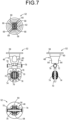
- FIGS. 9 and 10 show an embodiment of the refill container.
- a refill container 100 may be any as long as it can store the treatment liquid 12 for a long period of time, and the material, shape, structure, capacity, etc. are not limited, but a sufficient capacity is stored while preventing unintended leakage.
- containers with a structure wherein a plug 108 having a spout 106 is fixed to an opening 104 of a bottle body 102 opening upward by welding or screwing, can be adopted.
- the refill container 100 of the present embodiment includes the spout 106 having a small diameter and a tapered cylinder shape that protrudes upward from the central portion of the plug 108.
- a male thread is provided on the outer peripheral surface of the spout 106 so that a cap (not shown) can be attached when the refill container 100 is not used.
- the spout 106 has an outlet 110 opens at its tip end. Inside the spout 106, a small circular block-shaped valve body 112 serving as a shutoff valve body is provided inside the spout 106. The valve body 112 is pressed from the inside against the outlet 110 so as to close the outlet 110.
- the valve body 112 is urged from the inside by a coiled resin spring 114 as an urging means, and is urged from the inside to a tapered or stepped inner peripheral surface at the proximal end side of the circular outlet 110, whereby the outlet 110 can be held in a cutoff state.
- the resin spring 114 has a tapered double helix structure.
- the resin spring 114 has a fixing ring 116 that is fitted and fixed to the inner peripheral surface of the spout 106 at the base end portion having a large diameter.
- the resin spring 114 is integrated with the valve body 112 at the tip portion having a small diameter.
- the valve body 112 is provided with an operating protrusion 118 serving as a protrusion that protrudes outward from the central portion, and the operating protrusion 118 is inserted into the outlet 110 of the spout 106 and protrudes outward.
- the operating protrusion 118 has a size and shape such that a gap extending in the vertical direction is formed between the operating protrusion 118 and the inner peripheral surface of the outlet 110.
- three concave vertical grooves 120 extending in the vertical direction on the outer peripheral surface of the operating protrusion 118 are formed at equal intervals in the circumferential direction, so that the cross-sectional shape of the operating protrusion 118 is substantially radiated.
- the vertical groove 120 forms a gap extending in the vertical direction in the outlet 110.
- valve body 112 By pushing the tip of the operating protrusion 118 protruding outward from the outlet 110, the valve body 112 is moved inward against the urging force of the resin spring 114. With the valve body 112 is moved inward and is separate from the outlet 110, the valve body 112 is switched to the open state.
- the internal space of the refill container 100 is communicated with the outside through the gap between the inner peripheral surface of the outlet 110 and the vertical groove 120 of the operating protrusion 118, and the treatment liquid 12 contained in the refill container 100 is allowed to outflow.
- the valve body 112 is pressed against the inner peripheral surface on the base end side of the outlet 110 by the urging force of the resin spring 114 to be in a closed state.
- the outlet 110 automatically returns to the cutoff state.
- the refill container 100 By using the refill container 100 as described above, it is possible to prevent the contained treatment liquid 12 from inadvertently flowing out unless the operating protrusion 118 is pushed in, thereby preventing unintentional scattering of the treatment liquid 12 such as hydrogen peroxide solution.
- the treatment liquid 12 such as hydrogen peroxide solution.
- a portion where the operating protrusion 118 of the refill container 100 is pushed in to allow the treatment liquid 12 to flow out is specified, whereby scattering of the treatment liquid 12 to the surroundings upon injecting the treatment liquid 12 into the storage container or the like, is more effectively prevented.
- the insertion port 42 formed in the central portion of the lid 20 in the lens case 10 is sized so that the spout 106 of the refill container 100 can be inserted. Then, in an upright state in which the bottom wall 30 of the case body 18 is placed on a horizontal support table or the like, the refill container 100 is turned upside down and the spout 106 directed downward is inserted into the lens case 10 from the insertion port 42 of the lid 20.
- the container receiving portion 48 of the lens case 10 has a slightly larger inner peripheral surface shape substantially corresponding to the spout 106 of the refill container 100. Then, the spout 106 inserted from the insertion port 42 of the lid 20 pushes and opens the slit 56 of the packing 46 and enters the container receiving portion 48. At that time, the inner peripheral surface of the insertion port 42 and the container receiving portion 48 is slightly larger than the outer peripheral surface of the spout 106. This generates a guiding action with respect to the spout 106 to be inserted due to direct contact with the spout 106 or contact via the packing 46 with the spout 106, making it possible to avoid a large inclination or catching of the spout 106.
- the packing 46 made of an elastomer can exert an elastic holding action and / or a sealing action, and the spout 106 of the refill container 100 is further stabilized by the inner peripheral surface of the container receiving portion 48.
- the protruding tip of the operating protrusion 118 protruding from the tip of the spout 106 is brought into contact with the central portion of the bottom wall 66 of the receiving portion 48. Further, the protruding tip of the operating protrusion 118 is pressed against the bottom wall 66 of the container receiving portion 48 due to the weight or operating force of the refill container 100, so that the operating protrusion 118 is pushed inward of the refill container 100.
- the tip of the spout 106 of the refill container 100 abuts directly against the bottom wall 66 of the container receiving portion 48 or indirectly via the operating protrusion 118, and the insertion depth of the spout 106 into the insertion port 42 is limited.
- the periphery of the spout 106 is also held by the insertion port 42 and the peripheral wall 60 of the container receiving portion 48, so that the spout 106 is positioned with respect to the refill container 100.
- the operating protrusion 118 is pushed inward of the refill container 100, so that the valve body 112 moves inward, and the closure by the valve body 112 is released and the valve body 112 is set to the open state without any special valve operation.
- the treatment liquid 12 contained in the refill container 100 is injected into the lens case 10 from the spout 106 through the gap between the inner peripheral surface of the outlet 110 and the vertical groove 120 of the operating protrusion 118.
- the bottom wall 66 of the container receiving portion 48 with which the tip end portion of the spout 106 abuts has a lattice structure, and the treatment liquid 12 flowing out from the outlet 110 passes through the lower window 68 of the bottom wall 66 and flows downward where the support portion 50 for the contact lenses 16, 16 is arranged.
- the bottom wall 66 of the lattice structure is located below the opening direction of the outlet 110, i.e., a front of the opening direction of the outlet 110, where the flow of the treatment liquid 12 poured from the outlet 110 is large.
- the bottom wall 66 of the lattice structure constitutes a surface-shielding portion to which the treatment liquid 12 flowing toward the front (downward) in the opening direction hits.
- the bottom wall 66 of the lattice structure located immediately in front of the spout 106 in the opening direction also has a substantially triangular cross-sectional shape in which the width dimension gradually decreases toward the upper end facing the spout 106.
- the rebounding of the treatment liquid 12 due to the bottom wall 66 of the lattice structure is suppressed. If, among the treatment liquids 12 flowing out from the outlet 110, there is a treatment liquid 12 that bounces off the bottom wall 66 or a treatment liquid 12 that cannot completely flow down from the lower window 68 of the bottom wall 66, the treatment liquid 12 can flow into the storage area 14 through the side windows 64 of the peripheral wall 60 of the container receiving portion 48.
- the treatment liquid 12 of the refill container 100 is poured out from the outlet 110 of the spout 106 in the container receiving portion 48, and is guided downward through the lower window 68 of the container receiving portion 48 as a guide flow path.
- the treatment liquid 12 poured from the refill container 100 can be guided into the into the storage area 14, while preventing being scattered to the outer periphery of the lens case 10 by the peripheral wall 60 of the container receiving portion 48, the packing 46, the lid 20 and the like.
- the injection position of the treatment liquid 12 is also stably set to a predetermined position. It is desirable to design that no plane (a plane that spreads in the horizontal direction) that is orthogonal to the vertical direction that is the outflow direction is provided below the outlet 110, i.e., in the opening direction of the outlet 110. As a result, it is possible to more effectively prevent the treatment liquid 12 that has been vigorously flowed downward from the outlet 110 from bouncing upward and leaking to the outside through, for example, a gap in the packing 46.
- a treatment set with an ocular device case including the lens case 10 or the refill container 100 of the present embodiment it is possible to realize the operation of injecting the treatment liquid 12 into the lens case with less scattering.
- the problem that the scattered hydrogen peroxide solution or the like adheres to the fingers and unintentionally irritates the eyes of the lens user is effectively prevented.
- the pair of contact lenses 16, 16 are both located below the outlet 110 when the treatment liquid 12 is injected into the lens case 10, and the central axis of the lens is substantially horizontal. Since it is held by the support portion 50 in the facing state, it can be effectively prevented that the injected treatment liquid 12 directly hits the surface of the contact lens 16 and rebounds.
- the lens case 10 of the present embodiment has a double wall structure in which the peripheral wall 24 of the case body 18 has a substantially straight cylindrical inner peripheral wall 24b and an outer peripheral wall 24a extending downward.
- Excellent stability due to the wide bottom surface when placed on a table or the like can be improved while avoiding an unnecessary increase in the amount of treatment liquid.
- a force that pushes the outlet 110 of the refill container 100 downward, when injecting the treatment liquid 12 acts on the container receiving portion 48. Therefore, to improve the stability of the case body 18 when placed on a table or the like, is effective in preventing the lens case 10 from being unintentionally tilted due to tilting in the pressing direction or the like.
- the refill container 100 with a valve provided with the valve body 112 at the outlet 110 of the spout 106 is adopted. Therefore, when injecting the treatment liquid 12 into the lens case 10 by the refill container 100, even if the refill container 100 is tilted or inverted, the unintended outflow of the treatment liquid 12 can be prevented until the operating protrusion 118 at the tip of the outlet 110 is pressed against the bottom wall 66 of the container receiving portion 48 and pushed inward. Therefore, unintentional spillage or splattering of the treatment liquid during the injection operation of the treatment liquid 12 into the lens case 10 can be prevented more effectively.
- the packing 46 makes it possible to expand / contract the opening area of the insertion port 42 based on the elastic deformation action. In a state where the spout 106 of the refill container 100 is not inserted, the packing 46 can provide a function as a valve body that reduces the opening area compared to a state where the spout 106 of the refill container 100 is inserted.
- the packing 46 elastically deforms to open the slit 56 to allow the spout 106 to be inserted, while when the spout 106 is pulled out, the packing 46 is elastically deformed and returns to the original plate shape so as to closes the slit 56.
- the outflow of gas generated by the pressure increase in the storage area 14 due to the decomposition of the hydrogen peroxide solution or the like is allowed through the slit 56, and when the lens case 10 is tilted or falls, it can also exert the effect of suppressing the leakage amount of the treatment liquid 12.
- the treatment liquid 12 can be injected into the storage area 14 in which the catalyst 32 is arranged in a state where the contact lenses 16 and 16 are supported at predetermined positions in the storage area 14. Therefore, at the same time as injecting the treatment liquid 12 into the storage area 14, treatment such as sterilization of the contact lenses 16 and 16 is started, and at the same time, a decomposition reaction or the like by catalytic action of the treatment liquid 12 such as hydrogen peroxide solution is started.
- pre-initiation of the decomposition reaction of the treatment liquid 12 with a catalyst 32 before the insertion of the contact lenses 16 and 16, which may be regarded as a problem when the contact lenses 16 and 16 are inserted into the storage area 14 after the injection of the treatment liquid 12 into the storage area 14 is completed, can also be avoided.
- the refill container used for injecting the treatment liquid 12 into the lens case 10 is not limited to the refill container 100 of the above-described embodiment, and the valve body 112 may not be provided in the spout 106.
- the spout 106 of the plug 108 may be provided so as to be inclined with respect to the central axis of the bottle body 102 and to protrude toward, for example, laterally or diagonally upward.
- the specific structure, shape, size, etc. of the lens case 10 can be changed.
- the storage area 14 having a depth larger than the width is used to hold the contact lens 16 in a substantially vertical state.
- the storage area having a large width compared to the depth may be adopted.
- the contact lens 16 is provided with a convex or concave support surface for supporting the front surface or the rear surface of the lens from below in a state where the optical axis of the contact lens 16 is substantially in the vertical direction, and the contact lens 16 is held in a flat state.
- the container receiving portion and the contact lens support portion do not need to be integrally provided on the lid, and the container receiving portion and the contact lens support portion are also separated.
- the container receiving portion may be provided on the lid side, while the support portion of the contact lens may be provided on the container body side.
- the spout 106 of the refill container 100 is inserted through the insertion port 42 of the lid 20, and the treatment liquid 12 is injected into the storage area 14. It is also possible to provide a container receiving portion that allows injection into the storage area from the spout at a place different from the lid. Specifically, for example, a container receiving portion that allows injection of the treatment liquid may be provided at a position of the case body that is offset from the mounting position of the lid to the side or downward. Further, the injection port of the refill container may be inserted from the side into the case body or the lid.
- the support portion of the contact lens and the container receiving portion are provided separately from the lid. Therefore, it is also possible to adopt a mode in which the treatment liquid is injected into the storage area in which the contact lens is accommodating and supported without the lid being attached. It is also possible to adopt a container receiving portion that appears with the lid member open. Further, it is also possible to adopt a mode in which the treatment liquid can be poured into the storage area in which the contact lens is supported in the state where the lid is closed by the lid of the case body without providing the container receiving portion for receiving the spout of the refill container.
- the refill container 100 employs the structure in which the outlet 110 is opened by pressing the operating protrusion 118 against the container receiving portion 48 of the lens case 10 and pushing it inward.
- various valve means that are opened by contact with respect to the lens case or the like can be adopted.
- an elastic valve with a slit is attached to the outlet, and a male luer-shaped hollow pin is provided so as to project from the container receiving portion of the contact lens case.
- the elastic valve may be opened by inserting it into the slit of the elastic valve.
- the container receiving portion to which the spout of the refill container is brought into contact is not limited to the bottomed tubular shape as described above.
- the spout of the refill container does not have a valve means that opens by pressing, it is also possible to form a container receiving portion into a cylindrical shape or an arc shape without a bottom, thereby exerting a positioning action in a specific direction by abutting the spout of the refill container with the container receiving portion.
- the treatment liquid 12 is not limited to ones of the illustrated embodiment, and may be used for storage treatment, disinfection, cleaning and the like of an ocular device such as a contact lens 16.
- adaptable treatment liquid may include any of a peroxide selected from hydrogen peroxide, perboric acid, peracetic acid, performic acid, and salts thereof, or an oxide of chlorine selected from chlorine dioxide, chlorite, hypochlorite, and salts thereof, or povidone-iodine.
- the catalyst 32 illustrated in the embodiments is also used as appropriate for the treatment liquid 12, and the presence or absence and type of catalyst 32 is not limited.
- the catalyst such as platinum illustrated for the treatment liquid of hydrogen peroxide water
- tablets of enzymes such as catalase can also be employed.
- the tablets can be introduced into the case body before injection of the treatment liquid.
- a povidone-iodine disinfectant other than hydrogen peroxide water as the treatment liquid 12
- neutralizing tablets such as sodium sulfite or ascorbic acid.
- an ocular device case can be integrally or additionally provided with other functional means, for example: a timer for measuring the processing time and the like; a display means for showing processing status by light, sound, or the like; and a sensor or a monitor for measuring the degree of dirt on the ocular device or confirming damage such as chipping.
- the present invention can also be effectively applied to an ocular device case or a treatment liquid set provided with such functional means. Furthermore, the specific shape and size of the case can be appropriately changed depending on the lens or the like to which the invention is applied. The present invention can also be applied to a case used for a single or three or more ocular devices.
- a first preferred aspect provides an ocular device case that is used by injecting a treatment liquid from a separate refill container, the device comprising: a case body having a storage area for the treatment liquid; a support portion for supporting an ocular device in the storage area; a lid attached to an opening of the storage area in the case body; and a container receiving portion being configured to be brought into contact with a spout of the refill container to allow the treatment liquid to be injected into the storage area, with the ocular device being supported in the storage area by the support portion.
- the treatment liquid can be injected from the refill container into the storage area in a state where the spout of the refill container contacts with the container receiving portion and being positioned at a predetermined site. Therefore, for example, when a user of an ocular device injects a treatment liquid from a refill container into a storage area, it is able to avoid an injection mode in which the amount of splattering of the treatment liquid tends to be large, such as vigorously injecting the treatment liquid from a position far above, or injecting the treatment liquid directly onto the device and so as to pour it vigorously over the entire surface. This makes it possible to encourage users to do an operation of inj ecting a treatment liquid with less splattering.
- the treatment liquid can be injected into the storage area while the ocular device is supported in the storage area, the target treatment such as sterilization by the treatment liquid of the ocular device can be started substantially at the same time as the injection of the treatment liquid.
- the second preferred aspect provides the ocular device case according to the first preferred aspect, wherein the container receiving portion is arranged to be contact with the spout of the refill container pointed downward from above, in an upright state of the case body to which the lid is attached.
- the treatment liquid can be injected from the refill container into the storage area in a state where the lid is attached to the opening of the case body and there is no large opening. Therefore, it is possible to prevent the injected treatment liquid from splashing to the outside through the large opening. Further, since the refill container can be brought into contact with the case from above in the upright state of the case body for injection, for example, stable holding of the case at the time of injection and operation of injecting the treatment liquid can be more easily realized.
- the third preferred aspect provides the ocular device case according to the first or second preferred aspect, further comprising an insertion port into which the spout of the refill container is inserted, wherein the container receiving portion is located inward of the insertion port.
- the treatment liquid will be injected into the storage area through the opening at the tip of the spout. Therefore, even if the treatment liquid bounces off in the storage area, it can be reduced that the treatment liquid jumps out to the outside of the container and is scattered.
- a fourth preferred aspect provides the ocular device case according to the third preferred aspect, wherein the insertion port is provided with a valve body that reduces an opening area of the insertion port in a state where the spout of the refill container is not inserted into the insertion port, rather than a state where the spout is inserted.
- a fifth preferred aspect provides the ocular device case according to the fourth preferred aspect, wherein the valve body comprises an elastic valve capable of increasing and decreasing the opening area of the insertion port based on elastic deformation action thereof.
- the opening of the insertion port can be made sufficiently small or substantially closed when the spout of the refill container is not inserted, while the necessary opening area is secured when the spout of the refill container is inserted, for example.
- a sixth preferred aspect provides the ocular device case according to the fourth or fifth preferred aspect, wherein the valve body restricts a passage of the treatment liquid.
- the ocular device case of this aspect for example, when the spout of the refill container is not inserted, it is possible to suppress the leakage of the treatment liquid to the outside through the insertion port.
- the ocular device case is moved with the treatment liquid being contained, it is also possible to prevent or suppress the careless leakage of the treatment liquid in the storage area to the outside due to vibration or the like.
- a seventh preferred aspect provides the ocular device case according to any one of the fourth through sixth preferred aspects, wherein the valve body allow a passage of gas in a state where the spout of the refill container is not inserted.
- An eighth referred aspect provides the ocular device case according to any one of the third through seventh preferred aspects, wherein an insertion depth of the spout of the refill container with respect to the insertion port is limited by a contact of a tip of the spout of the refill container with the container receiving portion.
- the user when the user injects the treatment liquid from the refill container, the user is allowed to insert the spout of the refill container into the insertion port until the tip of the spout abuts on the container receiving portion. It becomes possible to stably specify the insertion length of the spout of the refill container with respect to the insertion port. This makes it possible to prevent or suppress that the treatment liquid leaks due to insufficient insertion depth of the spout of the refill container with respect to the insertion port, or that the insertion depth of the spout of the refill container with respect to the insertion port is too deep to interfere with the ocular device or to put an undesirable load on the valve body.
- a ninth referred aspect provides the ocular device case according to any one of the first through eighth preferred aspects, wherein a contact position of a tip of the spout of the refill container in the container receiving portion is set above a prescript position of an liquid surface level of the treatment liquid in the storage area.
- the spout of the refill container may be prevented from being unnecessarily contacted with the treatment liquid filled in the storage area. This makes it possible to avoid backflow of the treatment liquid filled in the storage area to the refill container. In addition, it is also possible to prevent or suppress the invasion of various germs in the treatment liquid filled in the storage area into the refill container and the transfer of germs or the like adhering to the vicinity of the spout to the treatment liquid filled in the storage area.
- a tenth referred aspect provides the ocular device case according to any one of the first through ninth preferred aspects, wherein the treatment liquid comprises a liquid that foams during treatment with the ocular device, and a contact position of a tip of the spout of the refill container in the container receiving portion is set at a position that is equal to or below a maximum level of a level fluctuation of an liquid surface level of the treatment liquid due to foaming thereof.
- the remained liquid can be circulated within the storage area by the treatment liquid that reaches the container receiving portion due to foaming thereof. Therefore, even if the treatment liquid remains in the container receiving portion, it is possible to avoid the problem that the remaining treatment liquid such as hydrogen peroxide solution is not neutralized and remains as an irritant or is contaminated.
- An eleventh referred aspect provides the ocular device case according to any one of the first through tenth preferred aspects, wherein the ocular device is supported in the storage area by the support portion, and an agent acting on the treatment liquid is accommodating and arranged in the storage area of the case body with the lid being attached.
- the treatment liquid is injected from the refill container into the storage area in a state that the ocular device is placed in the storage area where the agent acting on the treatment liquid is arranged.
- the sterilization treatment of a contact lens with a hydrogen peroxide solution for example, it is also possible to avoid that the decomposition of the hydrogen peroxide solution by a catalyst as an agent arranged in the storage area starts at a stage before the contact lens is immersed in the solution.
- a twelfth referred aspect provides the ocular device case according to any one of the first through eleventh preferred aspects, wherein the container receiving portion is provided with a guide flow path that guide the treatment liquid injected from the spout downward from the contact position of a tip of the spout of the refill container.
- the treatment liquid flowing out from the spout of the refill container can be guided to a predetermined specific place set in advance by the guide flow path and filled in the storage area. Therefore, it is possible to set the flow of the treatment liquid at a place where the injection operation of the treatment liquid is less likely to scatter, and to realize a more stable injection state.
- the guide flow path may be configured by, for example, a concave groove extending downward from the contact position of the tip of the spout with a downward slope, a tunnel-shaped hole, or a combination thereof.
- a concave groove extending downward from the contact position of the tip of the spout with a downward slope, a tunnel-shaped hole, or a combination thereof.
- the guide flow path having a tunnel-shaped hole it is possible to more reliably prevent the treatment liquid from scattering around the hole by the peripheral wall of the hole.
- the guide flow path does not have to be single and a plurality of guide flow paths may be provided, or a guide flow path in a form of splitting or merging may be adopted.
- the container receiving portion is provided with a surface-shielding portion located in front of a tip opening of the spout of the refill container in its opening direction and to which the treatment liquid flowing out from the spout and flowing toward the front in the opening direction of the spout.
- the momentum of the flow of the treatment liquid poured from the refill container into the storage area is large in the direction toward the front of the tip opening of the spout.
- suppression of the flow rate of the treatment liquid by means of the surface-shielding portion makes it possible to reduce the rebound of the treatment liquid from the liquid surface, the ocular device, the support part, etc.
- by appropriately setting the shape of the surface-shielding portion it is possible to guide the injected treatment liquid into the storage area while guiding it in a specific direction.
- a thirteenth referred aspect provides the ocular device case according to any one of the first through twelfth preferred aspects, wherein a surface of the container receiving portion is coated with a water-repellent or hydrophobic surface coat.
- the treatment liquid injected into the storage area is prevented from adhering to the container receiving portion or is swiftly flowed downward after adhering. This makes it possible to avoid that the treatment liquid adheres to and remains in the container receiving portion. Therefore, this aspect is effective to solve the problems such that the treatment liquid adhering to the container receiving portion is evaporated and a specific component may be increased, or that the hydrogen peroxide solution as the treatment liquid may remain without being decomposed by the catalyst.
- a fourteenth preferred aspect provides the ocular device case according to any one of the first through thirteenth preferred aspects, wherein the case body includes an opening that opens the storage area upward, the lid is attached to the opening, and the lid is provided with the support portion that is inserted into the storage area from the opening, while the lid is provided with an insertion port into which the spout of the refill container is inserted, the container receiving portion being provided to be positioned below the insertion port and above a support position of the ocular device by the support portion in an upright state of the case body to which the lid is attached.
- the structure of the container body can be simplified by providing the support portion and the insertion port.
- the insertion port is provided on the lid and the insertion port does not function unless the lid is attached to the container body.
- this arrangement makes it possible to guide the user easily and precisely perform a series of processes of attaching the lid to the case body after the ocular device being supported by the support portion provided in the lid, and then injecting the treatment liquid from the spout into the storage area to fill the storage area.
- the position of the container receiving portion in the upright state of the case body to which the lid is attached is set below the insertion slot and above the support position of the ocular lens. Therefore, when the user injects the treatment liquid, the spout of the refill container can be easily positioned by the insertion slot, and it is also easy to avoid the spout inadvertently interfering with the ocular device.
- a fifteenth preferred aspect provides the ocular device case according to any one of the first through fourteenth preferred aspects, wherein the treatment liquid comprises any one of the following [1], [2], and [3], and is used for a purpose of disinfecting or cleaning the ocular device: [1] a peroxide selected from hydrogen peroxide, perboric acid, peracetic acid, performic acid, and salts thereof; [2] an oxide of chlorine selected from chlorine dioxide, chlorite, hypochlorite, and salts thereof; and [3] Povidone Iodine.
- the ocular device case of this aspect is capable of reducing inadvertently scattering of the treatment liquid to the outside of the case, when the user of the ocular device performs sterilization, disinfection, cleaning, etc. of the ocular device by using hydrogen peroxide solution or the like as a treatment liquid that causes great irritation when it enters the eye. Therefore, the risk of eye irritation by the scattered treatment liquid through the fingers may be reduced.
- a sixteenth preferred aspect provides the ocular device case according to any one of the first through fifteenth preferred aspects, wherein the ocular device comprises: a contact lens for vision correction such as myopia, hyperopia, and presbyopia; a cosmetic contact lens such as iris coloring and limbal dilation; a special contact lens such as a myopia suppression contact lens, an orthokeratology contact lens; a contact lens for conical corneal; a functional contact lens equipped with sensors, communication functions, imaging functions, etc.; and an intraocular lens such as a non-crystal type or a crystal type.
- a contact lens for vision correction such as myopia, hyperopia, and presbyopia
- a cosmetic contact lens such as iris coloring and limbal dilation
- a special contact lens such as a myopia suppression contact lens, an orthokeratology contact lens
- a contact lens for conical corneal a functional contact lens equipped with sensors, communication functions, imaging functions, etc.
- an intraocular lens such as a non-crystal type or
- the ocular device case of this aspect can be provided for distribution, storage, sterilization, and the like, in various mode that meet each of types of ocular lenses, each need of each user such as specialists and general users.
- a refill container for injecting the treatment liquid an individual small-capacity bottle type used by general users is adopted, and a large-capacity tank type including the treatment liquid supply line used by the manufacturer on the production line is adopted.
- a seventeenth preferred aspect provides an ocular device case that is used by injecting a treatment liquid from a separate refill container, the device comprising: a case body having a storage area for the treatment liquid; a support portion for supporting an ocular device in the storage area; and a lid attached to an opening of the storage area in the case body, wherein the case is arranged to allow pouring the treatment liquid into the storage area in a state where the case body is closed by the lid.
- the treatment liquid can be poured and injected from the refill container into the storage area with the lid being attached to the opening of the case body and having no large opening. Therefore, it is possible to prevent the treatment liquid that has flowed into the storage area from scattering to the outside through the large opening, and it is possible to induce the user to perform the injection operation of the treatment liquid with less scattering.
- a eighteenth preferred aspect provides a refill container that is used in combination with the ocular device case according to any one of the first through seventeenth preferred aspects, and that contains the treatment liquid to be injected into the ocular device case, the refill container comprising: a spout through which the treatment liquid flows out; and a shutoff valve body having a protrusion protruding outward from a tip of the spout; wherein the shutoff valve body is assembled in the spout such that the shutoff valve body is urged from an inside toward an outside of the spout with the protrusion protruding outward to block the spout, and with the protrusion at the spout being brought into contact with the container receiving portion of the ocular device case and pushed inward, the spout opens to allow the treatment liquid to flow out from the spout.
- the treatment liquid can be discharged by opening the spout by pressing the protrusion protruding from the tip of the spout against the container receiving portion. Therefore, by pressing the tip of the spout of the refill container against the container receiving portion, the refill container can be stably positioned with respect to the ocular device case and the treatment liquid can be injected. Further, when the treatment liquid is injected into the ocular device case, the container receiving portion is positioned in front of the spout in its opening direction. Therefore, the treatment liquid flowing out vigorously from the spout of the refill container toward the front in the opening direction is likely to hits the container receiving portion, so that the treatment liquid is dispersed and the flow velocity is reduced. This makes it possible to reduce the scattering of the treatment liquid to the outside due to the rebound.
- a nineteenth preferred aspect provides a treatment set with a treatment liquid for an ocular device, wherein the ocular device case according to any one of the first through seventeenth preferred aspects and the refill container according to the eighteenth aspect are adopted in combination.
- the treatment set having a structure according to this aspect makes it possible to provide general users with a refill container having a spout appropriately matched to a container receiving portion provided in a ocular device case in combination with the ocular device case.
- the refill container according to the eighteenth preferred aspect is adopted. This makes it possible to prevent unintentional outflowing of the treatment liquid from the spout of the refill container away from the ocular device case, when the treatment liquid is injected into the ocular device case, for example, at the stage where the spout of the refill container is pressed by the container receiving portion of the ocular device case, or at the stage where the refill container is away from the ocular device case after injection. Namely, since the outlet of the treatment liquid in the refill container, i.e., the spout, is closed by the shutoff valve body, the treatment liquid does not unintentionally spill just by tilting the refill container.
- the rinse solution of the ocular device is generally used so as to pour directly onto the ocular device from the spout of the container facing downward.
- a shutoff valve body that does not allow the treatment liquid to flow out without being pushed the protrusion protruding from the spout into inside.
- a shutoff valve in a refill container for a treatment liquid such as a cleaning liquid or a disinfectant that is not suitable for a rinsing liquid even if the container is turned upside down and pressed against the peripheral wall of the container in order to mistakenly use for rinsing the treatment liquid contained in the refill container.
- a treatment liquid such as a cleaning liquid or a disinfectant that is not suitable for a rinsing liquid
Landscapes
- Health & Medical Sciences (AREA)
- Physics & Mathematics (AREA)
- Public Health (AREA)
- Veterinary Medicine (AREA)
- Epidemiology (AREA)
- Life Sciences & Earth Sciences (AREA)
- Animal Behavior & Ethology (AREA)
- General Health & Medical Sciences (AREA)
- Chemical & Material Sciences (AREA)
- General Chemical & Material Sciences (AREA)
- Chemical Kinetics & Catalysis (AREA)
- General Physics & Mathematics (AREA)
- Ophthalmology & Optometry (AREA)
- Optics & Photonics (AREA)
- Apparatus For Disinfection Or Sterilisation (AREA)
- Purses, Travelling Bags, Baskets, Or Suitcases (AREA)
- Eyeglasses (AREA)
- Closures For Containers (AREA)
Priority Applications (1)
| Application Number | Priority Date | Filing Date | Title |
|---|---|---|---|
| EP24192001.6A EP4432002A3 (de) | 2019-08-26 | 2019-08-26 | Augenvorrichtungsgehäuse und nachfüllbehälter für das augenvorrichtungsgehäuse |
Applications Claiming Priority (3)
| Application Number | Priority Date | Filing Date | Title |
|---|---|---|---|
| EP19943421.8A EP4023101B1 (de) | 2019-08-26 | 2019-08-26 | Gehäuse für eine okkularvorrichtung und nachfüllvorrichtung für dieses gehäuse für eine okularvorrichtung |
| PCT/JP2019/033395 WO2021038703A1 (ja) | 2019-08-26 | 2019-08-26 | 眼用デバイスケースおよび該眼用デバイスケースに用いられる補充容器 |
| EP24192001.6A EP4432002A3 (de) | 2019-08-26 | 2019-08-26 | Augenvorrichtungsgehäuse und nachfüllbehälter für das augenvorrichtungsgehäuse |
Related Parent Applications (1)
| Application Number | Title | Priority Date | Filing Date |
|---|---|---|---|
| EP19943421.8A Division EP4023101B1 (de) | 2019-08-26 | 2019-08-26 | Gehäuse für eine okkularvorrichtung und nachfüllvorrichtung für dieses gehäuse für eine okularvorrichtung |
Publications (2)
| Publication Number | Publication Date |
|---|---|
| EP4432002A2 true EP4432002A2 (de) | 2024-09-18 |
| EP4432002A3 EP4432002A3 (de) | 2024-12-18 |
Family
ID=74685385
Family Applications (2)
| Application Number | Title | Priority Date | Filing Date |
|---|---|---|---|
| EP24192001.6A Pending EP4432002A3 (de) | 2019-08-26 | 2019-08-26 | Augenvorrichtungsgehäuse und nachfüllbehälter für das augenvorrichtungsgehäuse |
| EP19943421.8A Active EP4023101B1 (de) | 2019-08-26 | 2019-08-26 | Gehäuse für eine okkularvorrichtung und nachfüllvorrichtung für dieses gehäuse für eine okularvorrichtung |
Family Applications After (1)
| Application Number | Title | Priority Date | Filing Date |
|---|---|---|---|
| EP19943421.8A Active EP4023101B1 (de) | 2019-08-26 | 2019-08-26 | Gehäuse für eine okkularvorrichtung und nachfüllvorrichtung für dieses gehäuse für eine okularvorrichtung |
Country Status (6)
| Country | Link |
|---|---|
| US (2) | US12029823B2 (de) |
| EP (2) | EP4432002A3 (de) |
| JP (3) | JP6892564B1 (de) |
| CN (1) | CN114269198A (de) |
| ES (1) | ES2991005T3 (de) |
| WO (1) | WO2021038703A1 (de) |
Families Citing this family (1)
| Publication number | Priority date | Publication date | Assignee | Title |
|---|---|---|---|---|
| WO2021038703A1 (ja) * | 2019-08-26 | 2021-03-04 | 株式会社メニコン | 眼用デバイスケースおよび該眼用デバイスケースに用いられる補充容器 |
Citations (2)
| Publication number | Priority date | Publication date | Assignee | Title |
|---|---|---|---|---|
| JP2004290473A (ja) | 2003-03-27 | 2004-10-21 | Jms Co Ltd | 医療用ゴム栓及び医療用容器 |
| JP4306967B2 (ja) | 1998-09-21 | 2009-08-05 | コロニス ゲーエムベーハー | コンタクトレンズのケア用装置 |
Family Cites Families (44)
| Publication number | Priority date | Publication date | Assignee | Title |
|---|---|---|---|---|
| US2242876A (en) * | 1939-08-08 | 1941-05-20 | Lee L Winters | Perfume dispenser |
| US3233727A (en) * | 1963-09-13 | 1966-02-08 | Karl H Wilson | Multiple use packaging container |
| FR1453313A (fr) * | 1965-06-02 | 1966-06-03 | Dupont S T | Système de jonction amovible étanche de deux réservoirs |
| US3473886A (en) * | 1967-04-12 | 1969-10-21 | Harry R Leeds | Medical sterilization apparatus |
| US3476507A (en) * | 1967-07-10 | 1969-11-04 | Harry R Leeds | Medical sterilization apparatus |
| US3643672A (en) | 1970-03-02 | 1972-02-22 | Frank E Brown | Contact lens case |
| JPS4928442U (de) * | 1972-06-15 | 1974-03-11 | ||
| US4415076A (en) * | 1981-11-23 | 1983-11-15 | Campbell Charles E | Soft contact lens container |
| US4637919A (en) * | 1984-11-05 | 1987-01-20 | Ryder International Corporation | Lens disinfecting appliance with improved venting feature |
| CA1277202C (en) * | 1985-04-11 | 1990-12-04 | Terry S. Floyd | Self-regulating valve |
| US5127517A (en) * | 1988-08-24 | 1992-07-07 | Alcon Laboratories, Inc. | System for storage and caring for contact lenses |
| JPH02112115U (de) * | 1989-02-28 | 1990-09-07 | ||
| ES2028513A6 (es) * | 1990-05-24 | 1992-07-01 | Dirygesa Sl | Valvula elastica para escape de fluidos. |
| US5089240A (en) * | 1990-08-22 | 1992-02-18 | Ciba Vision Corporation | Catalytic lens sterilizing system |
| AU655955B2 (en) * | 1990-11-30 | 1995-01-19 | Ciba Vision Corporation | Contact lens case venting system |
| US5250266A (en) * | 1990-11-30 | 1993-10-05 | Ciba Vision Corporation | Contact lens case venting system |
| IT1252058B (it) * | 1991-11-22 | 1995-05-29 | Dispositivo per il contenimento di lenti a contatto e dei recipienti contenenti liquidi di trattamento | |
| US5366078A (en) * | 1993-09-28 | 1994-11-22 | Bausch & Lomb Incorporated | Vented carrying case for contact lenses |
| US5558846A (en) * | 1994-12-05 | 1996-09-24 | Ciba Geigy Corporation | Apparatus for disinfecting contact lenses having improved vent means |
| US6000534A (en) * | 1996-08-16 | 1999-12-14 | Allergan Sales, Inc. | Contact lens disinfecting device and disinfection system |
| JP4749614B2 (ja) * | 2001-07-17 | 2011-08-17 | 株式会社メニコン | 眼用レンズ容器 |
| WO2004019114A1 (ja) * | 2002-08-12 | 2004-03-04 | Menicon Co., Ltd. | 含水性コンタクトレンズの水和処理ケースおよびそれを用いた水和処理方法 |
| US20040251146A1 (en) * | 2003-06-14 | 2004-12-16 | Ez-Eyez, Inc., | Compact lens solution and carrying case |
| US20060200100A1 (en) * | 2003-06-18 | 2006-09-07 | Rosati Coni F | Method and apparatus for supplying gas to an area |
| JP2005121907A (ja) * | 2003-10-16 | 2005-05-12 | Maisukii:Kk | レンズ洗浄液入り容器、コンタクトレンズ収納用品及びコンタクトレンズ洗浄セット |
| JP4339081B2 (ja) | 2003-11-14 | 2009-10-07 | 株式会社メニコン | コンタクトレンズ用の使い捨て処理ケース |
| US7331449B2 (en) * | 2004-02-20 | 2008-02-19 | Eli Pinchassi Dar | Combined contact lens case and solution storage device |
| US7998405B2 (en) * | 2006-07-07 | 2011-08-16 | Donley Keith K | Protecting the eyes of contact lens wearers |
| WO2008058326A1 (en) * | 2006-11-13 | 2008-05-22 | Baker Raymond J | Closure and dispensing system |
| DE202008002794U1 (de) * | 2008-02-27 | 2008-05-15 | Doniga, Cornelius | Kontaktlinsenbehälter mit Kompressions-Deckel |
| JP5350826B2 (ja) * | 2009-02-06 | 2013-11-27 | ロート製薬株式会社 | コンタクトレンズケアセット、レンズケースおよびケア剤容器 |
| US20100314418A1 (en) * | 2009-06-15 | 2010-12-16 | Donna Roth | Dispenser Adapted To Engage A Bottle And For Use With Consumable Fluid Having Solid Ingredients |
| US8459312B2 (en) * | 2009-06-30 | 2013-06-11 | Comar, Inc. | Press in bottle adapter |
| EP2493349B1 (de) * | 2009-10-29 | 2016-09-07 | The Compliance Case Corporation | Begrenzt verwendbares und selbstzerstörendes kontaktlinsengehäuse |
| JP2011251246A (ja) * | 2010-06-02 | 2011-12-15 | Menicon Co Ltd | 液処理装置 |
| WO2012002204A1 (ja) * | 2010-07-01 | 2012-01-05 | 株式会社メニコンネクト | 泡液兼用ディスペンサー |
| WO2012083140A1 (en) * | 2010-12-17 | 2012-06-21 | Novartis Ag | Pressure-venting container for disinfection and storage of contact lenses |
| KR200471034Y1 (ko) | 2011-11-17 | 2014-01-29 | 송재현 | 렌즈 세척 장치 |
| EP2870894B1 (de) * | 2012-07-09 | 2017-02-01 | Menicon Co., Ltd. | Kontaktlinsenbehälter |
| CN204232449U (zh) * | 2014-11-17 | 2015-04-01 | 重庆云帆医疗设备有限公司 | 双层储备型隐形眼镜盒 |
| CN104621916A (zh) | 2015-03-15 | 2015-05-20 | 邹思佳 | 一种旅行装隐形眼镜盒 |
| US9532632B2 (en) * | 2015-05-08 | 2017-01-03 | Better Vision Solutions LLC | Pressure-venting container for disinfection and storage of contact lenses |
| CN208463147U (zh) * | 2018-03-06 | 2019-02-05 | 朱盖想 | 一种隐形眼镜盒 |
| WO2021038703A1 (ja) | 2019-08-26 | 2021-03-04 | 株式会社メニコン | 眼用デバイスケースおよび該眼用デバイスケースに用いられる補充容器 |
-
2019
- 2019-08-26 WO PCT/JP2019/033395 patent/WO2021038703A1/ja not_active Ceased
- 2019-08-26 EP EP24192001.6A patent/EP4432002A3/de active Pending
- 2019-08-26 JP JP2020555535A patent/JP6892564B1/ja active Active
- 2019-08-26 US US17/637,519 patent/US12029823B2/en active Active
- 2019-08-26 EP EP19943421.8A patent/EP4023101B1/de active Active
- 2019-08-26 ES ES19943421T patent/ES2991005T3/es active Active
- 2019-08-26 CN CN201980099579.2A patent/CN114269198A/zh active Pending
-
2021
- 2021-05-27 JP JP2021089241A patent/JP7405793B2/ja active Active
-
2023
- 2023-12-14 JP JP2023210703A patent/JP7573718B2/ja active Active
-
2024
- 2024-06-06 US US18/735,418 patent/US20240316241A1/en active Pending
Patent Citations (2)
| Publication number | Priority date | Publication date | Assignee | Title |
|---|---|---|---|---|
| JP4306967B2 (ja) | 1998-09-21 | 2009-08-05 | コロニス ゲーエムベーハー | コンタクトレンズのケア用装置 |
| JP2004290473A (ja) | 2003-03-27 | 2004-10-21 | Jms Co Ltd | 医療用ゴム栓及び医療用容器 |
Also Published As
| Publication number | Publication date |
|---|---|
| US20220288269A1 (en) | 2022-09-15 |
| JPWO2021038703A1 (ja) | 2021-09-27 |
| CN114269198A (zh) | 2022-04-01 |
| JP6892564B1 (ja) | 2021-06-23 |
| EP4023101A1 (de) | 2022-07-06 |
| US20240316241A1 (en) | 2024-09-26 |
| JP7405793B2 (ja) | 2023-12-26 |
| WO2021038703A1 (ja) | 2021-03-04 |
| JP7573718B2 (ja) | 2024-10-25 |
| EP4023101A4 (de) | 2023-05-31 |
| JP2021142341A (ja) | 2021-09-24 |
| EP4023101B1 (de) | 2024-08-14 |
| JP2024015397A (ja) | 2024-02-01 |
| EP4432002A3 (de) | 2024-12-18 |
| US12029823B2 (en) | 2024-07-09 |
| ES2991005T3 (es) | 2024-12-02 |
Similar Documents
| Publication | Publication Date | Title |
|---|---|---|
| CA2542425C (en) | Contact lens case | |
| US20240316241A1 (en) | Ocular device case and refill container used for the ocular device case | |
| KR101789278B1 (ko) | 안약 투약기 | |
| US20070045354A1 (en) | Contact lens care product | |
| US20080208148A1 (en) | Ophthalmic Device | |
| HK40116737A (en) | Ocular device case and refill container used for the ocular device case | |
| US5334172A (en) | Fluid applicator for ocular prosthesis | |
| KR20160062637A (ko) | 투입이 용이한 안약 용기 | |
| HK40063189A (en) | Device case for eye and refill used for said device case for eye | |
| KR20160001595U (ko) | 점안액 투약 유닛 및 이를 포함하는 점안액 투약 장치 | |
| WO2019167147A1 (ja) | 眼用デバイスケースおよび眼用デバイスのケース付き処理液セット | |
| US20060282049A1 (en) | Eye fluid dispensing apparatus | |
| JP2011251246A (ja) | 液処理装置 | |
| KR102225866B1 (ko) | 안약 용기 | |
| JP7178873B2 (ja) | 点眼用容器 | |
| KR101518823B1 (ko) | 안약용기 | |
| KR20220106375A (ko) | 약액 디스펜서 | |
| US20070149932A1 (en) | Eye-drop dispensing eyecup | |
| JP2014157172A (ja) | コンタクトレンズ保存ケース | |
| TWI910927B (zh) | 防溢隱形眼鏡容器 | |
| KR101793930B1 (ko) | 점안 보조장치 | |
| JP2014157171A (ja) | コンタクトレンズ保存ケース | |
| JP2004261436A (ja) | 洗眼容器 | |
| KR20140090370A (ko) | 안약통 | |
| JP2001129054A (ja) | 点眼用アダプタを備えた目薬容器 |
Legal Events
| Date | Code | Title | Description |
|---|---|---|---|
| PUAI | Public reference made under article 153(3) epc to a published international application that has entered the european phase |
Free format text: ORIGINAL CODE: 0009012 |
|
| STAA | Information on the status of an ep patent application or granted ep patent |
Free format text: STATUS: REQUEST FOR EXAMINATION WAS MADE |
|
| 17P | Request for examination filed |
Effective date: 20240731 |
|
| AC | Divisional application: reference to earlier application |
Ref document number: 4023101 Country of ref document: EP Kind code of ref document: P |
|
| AK | Designated contracting states |
Kind code of ref document: A2 Designated state(s): AL AT BE BG CH CY CZ DE DK EE ES FI FR GB GR HR HU IE IS IT LI LT LU LV MC MK MT NL NO PL PT RO RS SE SI SK SM TR |
|
| REG | Reference to a national code |
Ref country code: DE Ref legal event code: R079 Free format text: PREVIOUS MAIN CLASS: G02C0013000000 Ipc: A45C0011040000 |
|
| PUAL | Search report despatched |
Free format text: ORIGINAL CODE: 0009013 |
|
| AK | Designated contracting states |
Kind code of ref document: A3 Designated state(s): AL AT BE BG CH CY CZ DE DK EE ES FI FR GB GR HR HU IE IS IT LI LT LU LV MC MK MT NL NO PL PT RO RS SE SI SK SM TR |
|
| RIC1 | Information provided on ipc code assigned before grant |
Ipc: A45D 34/00 20060101ALI20241111BHEP Ipc: A45C 11/00 20060101ALI20241111BHEP Ipc: G02C 13/00 20060101ALI20241111BHEP Ipc: A61L 12/12 20060101ALI20241111BHEP Ipc: A45C 11/04 20060101AFI20241111BHEP |
|
| REG | Reference to a national code |
Ref country code: HK Ref legal event code: DE Ref document number: 40116737 Country of ref document: HK |