EP4431981A1 - Ausgerichteter sensor - Google Patents
Ausgerichteter sensor Download PDFInfo
- Publication number
- EP4431981A1 EP4431981A1 EP24153800.8A EP24153800A EP4431981A1 EP 4431981 A1 EP4431981 A1 EP 4431981A1 EP 24153800 A EP24153800 A EP 24153800A EP 4431981 A1 EP4431981 A1 EP 4431981A1
- Authority
- EP
- European Patent Office
- Prior art keywords
- sensor
- wall
- housing
- module
- intermediate piece
- Prior art date
- Legal status (The legal status is an assumption and is not a legal conclusion. Google has not performed a legal analysis and makes no representation as to the accuracy of the status listed.)
- Granted
Links
Images

Classifications
-
- G—PHYSICS
- G01—MEASURING; TESTING
- G01S—RADIO DIRECTION-FINDING; RADIO NAVIGATION; DETERMINING DISTANCE OR VELOCITY BY USE OF RADIO WAVES; LOCATING OR PRESENCE-DETECTING BY USE OF THE REFLECTION OR RERADIATION OF RADIO WAVES; ANALOGOUS ARRANGEMENTS USING OTHER WAVES
- G01S7/00—Details of systems according to groups G01S13/00, G01S15/00, G01S17/00
- G01S7/48—Details of systems according to groups G01S13/00, G01S15/00, G01S17/00 of systems according to group G01S17/00
- G01S7/497—Means for monitoring or calibrating
- G01S7/4972—Alignment of sensor
-
- G—PHYSICS
- G01—MEASURING; TESTING
- G01S—RADIO DIRECTION-FINDING; RADIO NAVIGATION; DETERMINING DISTANCE OR VELOCITY BY USE OF RADIO WAVES; LOCATING OR PRESENCE-DETECTING BY USE OF THE REFLECTION OR RERADIATION OF RADIO WAVES; ANALOGOUS ARRANGEMENTS USING OTHER WAVES
- G01S7/00—Details of systems according to groups G01S13/00, G01S15/00, G01S17/00
- G01S7/48—Details of systems according to groups G01S13/00, G01S15/00, G01S17/00 of systems according to group G01S17/00
- G01S7/481—Constructional features, e.g. arrangements of optical elements
- G01S7/4811—Constructional features, e.g. arrangements of optical elements common to transmitter and receiver
- G01S7/4812—Constructional features, e.g. arrangements of optical elements common to transmitter and receiver transmitted and received beams following a coaxial path
-
- G—PHYSICS
- G01—MEASURING; TESTING
- G01B—MEASURING LENGTH, THICKNESS OR SIMILAR LINEAR DIMENSIONS; MEASURING ANGLES; MEASURING AREAS; MEASURING IRREGULARITIES OF SURFACES OR CONTOURS
- G01B11/00—Measuring arrangements characterised by the use of optical techniques
-
- G—PHYSICS
- G01—MEASURING; TESTING
- G01B—MEASURING LENGTH, THICKNESS OR SIMILAR LINEAR DIMENSIONS; MEASURING ANGLES; MEASURING AREAS; MEASURING IRREGULARITIES OF SURFACES OR CONTOURS
- G01B11/00—Measuring arrangements characterised by the use of optical techniques
- G01B11/24—Measuring arrangements characterised by the use of optical techniques for measuring contours or curvatures
- G01B11/25—Measuring arrangements characterised by the use of optical techniques for measuring contours or curvatures by projecting a pattern, e.g. one or more lines, moiré fringes on the object
-
- G—PHYSICS
- G01—MEASURING; TESTING
- G01B—MEASURING LENGTH, THICKNESS OR SIMILAR LINEAR DIMENSIONS; MEASURING ANGLES; MEASURING AREAS; MEASURING IRREGULARITIES OF SURFACES OR CONTOURS
- G01B11/00—Measuring arrangements characterised by the use of optical techniques
- G01B11/24—Measuring arrangements characterised by the use of optical techniques for measuring contours or curvatures
- G01B11/25—Measuring arrangements characterised by the use of optical techniques for measuring contours or curvatures by projecting a pattern, e.g. one or more lines, moiré fringes on the object
- G01B11/2504—Calibration devices
-
- G—PHYSICS
- G01—MEASURING; TESTING
- G01B—MEASURING LENGTH, THICKNESS OR SIMILAR LINEAR DIMENSIONS; MEASURING ANGLES; MEASURING AREAS; MEASURING IRREGULARITIES OF SURFACES OR CONTOURS
- G01B11/00—Measuring arrangements characterised by the use of optical techniques
- G01B11/24—Measuring arrangements characterised by the use of optical techniques for measuring contours or curvatures
- G01B11/25—Measuring arrangements characterised by the use of optical techniques for measuring contours or curvatures by projecting a pattern, e.g. one or more lines, moiré fringes on the object
- G01B11/2518—Projection by scanning of the object
-
- G—PHYSICS
- G01—MEASURING; TESTING
- G01S—RADIO DIRECTION-FINDING; RADIO NAVIGATION; DETERMINING DISTANCE OR VELOCITY BY USE OF RADIO WAVES; LOCATING OR PRESENCE-DETECTING BY USE OF THE REFLECTION OR RERADIATION OF RADIO WAVES; ANALOGOUS ARRANGEMENTS USING OTHER WAVES
- G01S17/00—Systems using the reflection or reradiation of electromagnetic waves other than radio waves, e.g. lidar systems
- G01S17/02—Systems using the reflection of electromagnetic waves other than radio waves
- G01S17/06—Systems determining position data of a target
- G01S17/42—Simultaneous measurement of distance and other co-ordinates
-
- G—PHYSICS
- G01—MEASURING; TESTING
- G01S—RADIO DIRECTION-FINDING; RADIO NAVIGATION; DETERMINING DISTANCE OR VELOCITY BY USE OF RADIO WAVES; LOCATING OR PRESENCE-DETECTING BY USE OF THE REFLECTION OR RERADIATION OF RADIO WAVES; ANALOGOUS ARRANGEMENTS USING OTHER WAVES
- G01S7/00—Details of systems according to groups G01S13/00, G01S15/00, G01S17/00
- G01S7/48—Details of systems according to groups G01S13/00, G01S15/00, G01S17/00 of systems according to group G01S17/00
- G01S7/481—Constructional features, e.g. arrangements of optical elements
- G01S7/4811—Constructional features, e.g. arrangements of optical elements common to transmitter and receiver
- G01S7/4813—Housing arrangements
Definitions
- the invention relates to a sensor module for a sensor, in particular an optoelectronic sensor module for an optoelectronic sensor, and a method for producing an aligned sensor module according to the preamble of claim 1 or 9.
- a common optoelectronic sensor is the laser scanner, which is suitable for detections and distance measurements that require a large horizontal angle range of the measuring system.
- a laser scanner a light beam generated by a laser periodically sweeps over a monitoring area with the help of a deflection unit. The light is remitted by objects in the monitoring area and evaluated in the laser scanner.
- the angular position of the deflection unit is used to determine the angular position of the object, and the distance of the object from the laser scanner is also determined from the light travel time using the speed of light in a phase or pulse method.
- the location of an object in the monitoring area is recorded in two-dimensional polar coordinates using the angle and distance information. This can be used to determine the positions of objects or to determine their contours.
- laser scanners are also used in safety technology to monitor a source of danger, such as a dangerous machine.
- a safety laser scanner is known from the DE 43 40 756 A1 known.
- a protective field is monitored which, during operation, the machine must not be accessed by the operating personnel. If the laser scanner detects an inadmissible intrusion into the protective field, such as an operator's leg, it triggers an emergency stop of the machine.
- Sensors used in safety technology must work particularly reliably and therefore meet high safety requirements, for example the EN13849 standard for machine safety and the EN61496 device standard for electro-sensitive protective devices (ESPD).
- ESD electro-sensitive protective devices
- Laser scanners are made up of a large number of individual parts with tolerances. This results in manufacturing variations for the light output and scanning plane: the height and alignment of the scanning plane vary to a certain extent from device to device. For cost reasons, it is not always possible to keep the tolerances in the laser scanner so small from the outset that the individual variations do not cause problems. In most applications, this means that manual alignment is necessary during installation. If the laser scanner is replaced later, the alignment must be repeated. In addition, brackets are required that enable alignment in the first place. Such brackets are expensive and require additional installation space.
- the EN 20 2015 106 370 U1 discloses another example of a holder for aligning a laser scanner. By means of a toothing of two holder parts, the already mounted laser scanner can still be rotated. From the EP 1 852 646 A2 and the US 2009/294619 A1 Adjustable mounts for a projector are known. None of these mounts overcome the disadvantages mentioned above.
- a sensor module for a sensor, in particular an optoelectronic sensor module for an optoelectronic sensor, and a method for producing an aligned sensor module according to claim 1 or 9.
- a sensor module is an assembly in which the actual sensor elements are combined. This can be, for example, a transmitting-receiving assembly for the sensor signals.
- the sensor module comprises a sensor unit. This is the functional core of the sensor module, whereby the precise structure depends on the respective sensor principle and sensor type.
- the sensor unit can, for example, have an image sensor or a simpler light receiver, possibly combined with a light transmitter.
- the sensor unit has a detection direction and a detection height with which the orientation can be characterized.
- this corresponds, for example, to the orientation of the optical axis and the height of its penetration point out of the sensor or into the sensor. In a camera, this describes the height of its field of view and how it is aligned. In an active optoelectronic sensor, such as a light sensor, the two quantities describe the orientation of the scanning beam and the height of the light exit in relation to the sensor.
- the sensor module also comprises a module housing in which the sensor unit is located.
- the term module housing is to be understood broadly.
- a first outer wall of the module housing is important, which can, for example, be designed as a base.
- the module housing preferably comprises further housing or outer walls, which make it a housing in the narrower sense and which preferably enclose the sensor unit on all sides. It is conceivable that in addition to the first outer wall, at least one further outer wall can take on its role, for example if the sensor module can be mounted optionally to the right or left on a wall or in an outer housing or, for example, can be turned upside down.
- the orientation and height position of the module housing and thus the detection direction and detection height of the sensor unit are determined.
- the flat base surface is that of an outer housing or an assembly or installation environment.
- the sensor module is arranged with the first outer wall as a reference surface on any wall of the outer housing, preferably at the bottom. Or it is placed on the floor or a workbench without an outer housing with the first outer wall as the underside or mounted on a wall with the first outer wall as the rear wall or side wall.
- height and detection height refer to an upright orientation. of the sensor with a horizontal flat base surface; in the case of side mounting, the height is to be understood as the lateral distance to the then vertical flat base surface, and similarly for any other orientation of the sensor and the flat base surface.
- the invention is based on the basic idea of giving the first outer wall a three-dimensional contour which, when arranged on the flat base surface, corrects the individual detection direction and/or detection height of the sensor unit.
- the first outer wall has a planar extension.
- the three-dimensional contour includes a third dimension perpendicular to the planar extension, which can be referred to as height or thickness. Local parts of the three-dimensional contour ensure that the detection direction is balanced, and its total thickness ensures that the detection height is balanced. Only the contact points and/or contact surfaces between the first outer wall and the flat base surface are relevant for the balancing function; the three-dimensional contour is ultimately arbitrary in between and can, for example, have smaller or larger recesses.
- the three-dimensional contour corrects only the detection direction, only the detection height, or both.
- each sensor module has an individual detection direction and detection height.
- a corresponding individual three-dimensional contour is created with a deviation from a conventional, flat outer wall in shape and/or thickness.
- the three-dimensional contour is shaped inversely to the individual deviations from a specified detection direction and/or detection height.
- the first outer wall is preferably raised to the same extent to the left in order to bring the sensor unit into the horizontal position specified in this example, and accordingly to the right or up and down for the vertical.
- the thickness or height of the first outer wall is reduced or increased overall by as much as the individual detection height deviates upwards or downwards from a specified detection height.
- the three-dimensional contour of the sensor module is fixed for the sensor module and is not designed for further modification. There are therefore no adjusting screws or anything like that, but the three-dimensional contour is a fixed property of the first outer wall. Of course, the three-dimensional contour can still be influenced using appropriate tools, but this is destructive misuse and therefore not an intended property of the sensor module.
- the invention has the advantage that the alignment of a sensor is automatically ensured during installation. This reduces the installation effort and the alignment result is guaranteed. Individual differences within a product family are balanced out, for example all laser scanners in a product family scan the same scanning plane. Adjustable alignment holders are no longer required. If a sensor is replaced, a new alignment is no longer required; the new device takes on the role of its predecessor according to the "plug & play" principle.
- the module housing is preferably arranged in a sensor housing of the sensor, with the flat base surface being a wall of the sensor housing or being firmly connected to it.
- the flat base surface does not have to be a wall of the sensor housing itself; it is sufficient if it is firmly connected to it.
- Other components of the sensor can be housed in the outer housing, such as evaluation electronics, a power supply or communication interfaces. Due to the invention, the sensor module can be mounted as a high-precision unit in the outer housing and thus the complete sensor. The sensor is then aligned and the tolerances discussed at the beginning are balanced.
- the sensor module is already the sensor itself, with the module housing also functioning as the sensor housing.
- the sensor module is identical to the sensor. Accordingly, there is no additional outer housing, although of course no one is prevented from placing a complete sensor in an outer housing again.
- the first outer wall with its three-dimensional contour ensures that the sensor is aligned when placed on the flat base or mounted on the flat base.
- the sensor is preferably a laser scanner or a radar with at least one scanning plane whose orientation is determined by the detection direction.
- the three-dimensional contour is very intuitive to understand: it reproduces an inclination of the scanning plane in inverted form as an inclined plane, whereby the three-dimensional contour does not have to be full-surface, as mentioned above.
- a laser scanner as already outlined in the introduction, a light transmitter generates transmitted light and sends it into the monitoring area. The transmitted light is received again as remitted transmitted light after it has been at least partially reflected by an object in the monitoring area.
- a control and evaluation unit is preferably designed to determine a distance of the object from a light travel time between the transmission of the transmitted light and the reception of the received light.
- a scanning movement is generated, preferably a rotary movement, with which the transmitted light and the received light are periodically emitted at different deflection angles or captured from different deflection angles.
- the scanning plane is thereby scanned.
- multi-layer scanners that have several transmitter/receiver pairs and thus scan several scan planes, in which case the detection direction refers to a selected one of the scan planes.
- a radar works in the same way on this abstract description level, whereby radar signals are generated and received instead of light.
- the first outer wall is preferably integrated into the module housing.
- the first outer wall is therefore an integral part of the module housing. Without the first outer wall, the module housing would be open on this side. This is to be understood as an alternative to an intermediate piece, which will be presented shortly.
- the first outer wall preferably has an inner housing wall and an intermediate piece arranged thereon.
- the intermediate piece is arranged between the inner housing wall and the flat base surface.
- the inner housing wall is preferably designed like a conventional housing, i.e. flat and of a uniform thickness to the rest of the module housing.
- the intermediate piece then has the three-dimensional contour.
- the inner housing wall contributes to the three-dimensional contour.
- the intermediate piece is preferably made in one piece.
- it is a mounting plate.
- Such an intermediate piece is inexpensive to produce and easy to handle.
- the intermediate piece is preferably connected to the inner housing wall and is made up of several parts, in particular as several similar pins, disks or threaded bushings that are inserted into the inner housing wall to different depths. Such an intermediate piece is therefore not brought into contact with the inner housing wall at the installation site, but is already attached to it. In principle, loose parts such as washers would also be conceivable, but this is more difficult to handle and entails a risk of confusion, which does not achieve the alignment.
- the intermediate piece can have a separate part for each support point, preferably three support points. Each of these parts can have an individual height or be shortened to an individual height.
- the parts are preferably identical to one another and inserted into the inner housing wall or module housing to different depths for a different effective height of the associated support points. It is conceivable to combine two or more support points in one part, for example to use an elongated part with two support points and a small further part with the third support point.
- the intermediate piece is preferably connected to the inner housing wall by mechanical interlocking, molding, pressing, magnetic force, screwing, gluing or welding.
- Hooks or a locking mechanism can be provided for a mechanical connection, or a positive connection can be created by fitting.
- Other connections, such as by magnets, screws, bolts, gluing or welding are also possible.
- the intermediate piece is preferably processed by removing material.
- an additive process or 3D printing is conceivable, with which an intermediate piece with the intended three-dimensional contour is produced.
- the three-dimensional contour can also be printed directly onto the outer wall and is then connected to it. This can be understood either as the outer wall then taking on the role of the inner wall and the print that of the intermediate piece, or that the outer wall including the three-dimensional contour is an outer wall integrated into the housing without an intermediate piece.
- a sensor unit is first produced and then individually assembled with the resulting component, installation or other tolerances.
- Detection direction and detection height are installed in a module housing with at least a first outer wall.
- the device is then arranged with the first outer wall on a flat base surface and the individual detection direction and/or the individual detection height is measured in order to determine a deviation from a specified or desired detection direction or detection height.
- the first outer wall is then provided with a three-dimensional contour that compensates for the deviations.
- the module housing is preferably arranged in a sensor housing on a wall of the sensor housing or on a reference surface firmly connected to it, which forms the flat base surface. This creates a sensor that is aligned with high precision.
- the sensor module is already the sensor and the module housing also functions as the sensor housing, so that the sensor is already manufactured with the sensor module.
- the first outer wall is preferably manufactured with the module housing and completely as part of the module housing.
- the first outer wall initially has an additional material or excess material, which is then partially removed in order to produce the three-dimensional contour.
- the additional material does not have to extend over the entire first outer wall; it is also possible to provide just a number of columns, legs or pins, which are individually shortened in order to produce the three-dimensional contour with corresponding contact points.
- the module housing is preferably initially manufactured with an inner housing wall, an intermediate piece with the three-dimensional contour is manufactured, and the intermediate piece is attached to the inner housing wall or arranged between the inner housing wall and the flat base surface, so that the inner housing wall and the intermediate piece together form the first outer wall.
- the intermediate piece can therefore either be connected to the module housing during production or remain loose at first and only be placed underneath or interposed at the place of use.
- An intermediate piece has the advantage that the sensor itself can remain unchanged and only a cost-effective intermediate piece is added.
- the intermediate piece is preferably manufactured by removing material from a blank.
- the three-dimensional contour is machined out of the blank, for example a mounting plate.
- the intermediate piece is manufactured by an additive process or 3D printing including the three-dimensional contour.
- the intermediate piece is preferably provided with a marking that indicates its affiliation with the sensor. This is particularly useful in an embodiment in which the intermediate piece initially remains loose.
- the marking makes it easy to clearly assign the intermediate piece to the sensor for which it was manufactured with its three-dimensional contour.
- a sensor serial number is suitable for this, which is usually located on the module housing or at least in the associated sensor documentation.
- the marking can be applied directly to the intermediate piece, for example with laser marking, but it is also conceivable to print it on an adhesive label or the like.
- the intermediate piece preferably has a marking and/or structure that allows it to be attached in the correct orientation.
- the intermediate piece is typically not symmetrical, which is precisely its purpose. If the intermediate piece initially remains loose, and also when the intermediate piece is attached during production, it must be correctly oriented. For this purpose, certain sides of the intermediate piece can be marked in color or with symbols. A basic shape that allows a clear orientation to be recognized is also conceivable. Structures on the intended connecting side of the intermediate piece and the inner housing wall are also possible in a pattern that only leads to mutual engagement in the correct orientation.
- the marking or structure can already be on the blank; unlike the marking on the preliminary step, it does not have to be individual. Instead, the three-dimensional contour is then manufactured to match the specified orientation.
- the intermediate piece preferably has several parts that are similar to one another and are inserted into the inner housing wall at different depths. Examples of this are pins or threaded bushings that are inserted so deeply that the protrusion creates the desired three-dimensional contour. Alternatively, it is conceivable to produce or keep several parts with different thicknesses or lengths and to connect a suitable selection to the inner housing wall. Alternatively, several parts can remain loose, but this is not user-friendly and prone to errors.
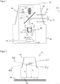
- FIG 1 shows a schematic sectional view through a laser scanner 10.
- a light transmitter 12 for example with a laser light source, generates a transmitted light beam 16 with the aid of a transmitting optics 14.
- the transmitted light beam 16 is emitted into a monitoring area 20 by means of a deflection unit 18.
- the transmitted light beam 16 can be at least partially surrounded by a transmitting tube (not shown).
- the transmitted light beam 16 is remitted by an object that may be present.
- the corresponding received light 22 returns to the laser scanner 10 and is detected by a light receiver 26 via the deflection unit 18 using a receiving optics 24.
- the receiving optics 24 is preferably a single converging lens, but additional lenses and other optical elements can be added.
- the light receiver 26 has, for example, at least one photodiode or, for greater sensitivity, an avalanche photodiode (APD) or an arrangement with at least one single photon avalanche diode (SPAD, SiPM).
- the deflection unit 18 is set into a continuous rotary motion at a scanning frequency by a motor 28. As a result, the transmitted light beam 16 scans a plane during each scanning period, i.e. a complete revolution at the scanning frequency.
- An angle measuring unit 30 is arranged on the outer circumference of the deflection unit 18 in order to detect the respective angular position of the deflection unit 18.
- the angle measuring unit 30 is formed here, for example, by a reticle disk as an angle measuring embodiment and a forked light barrier as a scanner.
- a control and evaluation unit 32 is connected to the light transmitter 12, the light receiver 26, the motor 28 and the angle measuring unit 30. By determining the light travel time between the emission of the transmitted light beam 16 and the reception of remitted received light 22, the distance of a scanned object from the laser scanner 10 is determined using the speed of light. The respective angular position at which the transmitted light beam 16 was emitted is known to the evaluation unit from the angle measuring unit 30.
- the interface 34 can be used for parameterization or other data exchange between the laser scanner 10 and the outside world.
- the interface 34 can be designed for communication in one or more conventional protocols, such as IO-Link, Ethernet, Profibus, USB3, Bluetooth, WLAN, LTE, 5G and many others.
- the interface 34 can be designed to be safe, in particular a safe output (OSSD, Output Signal Switching Device) for a safety-related shutdown signal when a protective field violation is detected.
- the laser scanner 10 is housed in a housing 36 which has a circumferential front panel 38.
- the light transmitter 12 and its transmitting optics 14 are located in a central opening of the receiving optics 24.
- the invention also includes alternative coaxial solutions, for example with a separate mirror area for the transmitted light beam 16 or with splitter mirrors, and also biaxial arrangements.
- the laser scanner 10 can use a rotating measuring head as a deflection unit instead of a rotating mirror, in which the light transmitter 12 and/or light receiver 26 rotate.
- Still other designs of a laser scanner 10 do not just scan a single scanning plane, but are multi-beam and thus designed as a multi-layer scanner. For the alignment to be explained shortly, one of the several scanning planes is then used, in particular a central scanning plane if available.
- a multi-layer scanner has several transmitter/receiver pairs that are offset in elevation from one another, whereby several light beams can be generated by a light source, for example by means of beam splitters or as a VCSEL array, and/or received in a matrix or, specifically, SPAD array.
- the invention is described using a laser scanner 10 as an example. However, it also includes other optoelectronic sensors, for example a light sensor whose scanning beam is to be aligned, a light grid with a large number of parallel detection beams or a 2D or 3D camera with alignment of its field of view. It also includes sensors that do not use an optical sensor principle. First of all, a radar should be mentioned, which also scans a scanning plane, even if this may be somewhat less clearly defined in elevation. Other sensors that are not exhaustively mentioned are ultrasonic sensors, capacitive, inductive or magnetic sensors, all of which, depending on the design and application of a require more or less precise alignment.
- the sensor according to the invention can be designed as a safety sensor in the sense of the standards mentioned in the introduction, in particular as a safety laser scanner, and can be used in safety technology to prevent accidents, for example by monitoring protective fields or evaluating the distance and speed of an object in the vicinity of a source of danger (speed and separation).
- the laser scanner 10 of the Figure 1 is a complete sensor, and the alignment of its housing 36 with respect to the outside, in particular a mounting surface, wall or the like, is explained below using this example.
- the invention can also be used in such a way that a sensor module such as a receiver module or a transmitter-receiver module is mounted in a sensor housing with high precision alignment.
- the reference surface is then not on the outside, but a wall or a reference surface of the sensor housing connected to it.
- the alignment principle in all variants is the same, thus transferable in an analogous manner, and is therefore not described separately.
- FIG 2 shows a schematic representation of a laser scanner 10 with illustration of two different scanning planes 40A-B due to manufacturing tolerances. Only the outer contours of a laser scanner 10 are shown below, for the other elements, please refer to the explanations of Figure 1
- the laser scanner 10 is arranged with a first outer wall 42 on a flat base surface 44. In Figure 2 This is shown in such a way that the laser scanner 10 is standing with its underside on the floor. Any other side of the laser scanner 10 can also be arranged on a base surface 44 with any other orientation, for example when mounted with the underside on the wall or with the top on the ceiling.
- the first outer wall 42 is the one that comes into contact with the flat base surface 44.
- the scanning plane 40A-B runs slightly differently in each laser scanner 10 as a result of component, installation or other tolerances, whereby Figure 2 This is clearly exaggerated. This is recorded by two quantities. Firstly, there is the orientation, which is characterized by a detection direction. This is because the inclination of the scanning plane 40A-B results from the direction of emission of the transmitted light beam 16. This is specified, for example, as an angle ⁇ A , ⁇ B to the base plane 44. Secondly, there is a detection height h A , hB , which is measured from the light emission area against a reference such as the lower end of the device.
- height is based on the Figure 2 shown upright orientation, with vertical mounting it is a lateral distance, corresponding with any inclination of the flat base surface 44, and all this is simply called height.
- the detection direction and detection height vary among laser scanners 10 of the same design, tolerances result in an individual detection direction and an individual detection height. These deviations require alignment and are not desired, but for cost reasons cannot be avoided at the source by reducing tolerances.
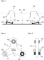
- Figure 3 shows a schematic representation of two laser scanners 10A-B, each with an individual intermediate piece 46A-B to compensate for the misalignment in the detection direction and/or detection height resulting from manufacturing tolerances.
- an intermediate piece 46A-B is manufactured individually, for example an intermediate plate that compensates for the inclination and height offset of the scanning planes 40A-B.
- the two scanning planes 40A-B now correspond to one another: They are at the same detection height and have the same, here horizontal, detection direction.
- the intermediate piece 46A-B forms the first outer wall 42 together with the actual, inner housing wall 48A-B. Thanks to the intermediate piece 46A-B, the first outer wall now has a three-dimensional contour with which the individual misalignment of the respective laser scanners 10A-B in the detection direction and/or detection height is individually compensated.
- the orientation of the scan plane 40A-B and/or the height of the light exit i.e. the individual detection direction or individual detection height
- the suitable intermediate piece 46A-B is manufactured individually if required.
- the intermediate piece 46 can be produced by removing material from a blank. Another possibility is an additive process such as 3D printing.
- the intermediate piece 46 By arranging the intermediate piece 46 between the inner housing wall 48A-B and the flat base surface 44, an individual adjustment or alignment is achieved. All laser scanners 10A-B of a product family can be brought to the same detection direction and/or detection height in this way. In contrast to, for example, adjusting screws or height-adjustable feet, this alignment can no longer be manipulated intentionally or inadvertently.
- the intermediate piece 46 can initially remain loose and only be inserted during assembly, or it can be attached to the laser scanner 10 in advance, again particularly during final production. Any fastening method is conceivable for this, such as hooks, magnetic force, screws, fitting, gluing, pressing or (laser) welding.
- the Figure 4 shows a top view and the Figure 5 shows a side view of an exemplary intermediate piece 46 with a compensating three-dimensional contour.
- three contact or support points 50a-c are sufficient according to the tripod principle. In other embodiments, there may be further contact points, contact surfaces or a full-surface contact.
- the support points 50a-c are widened to small areas, and inside them there is space for a respective screw hole 52 for fastening the laser scanner 10 to the flat base surface 44 by means of screws.
- the different heights of the support points 50a-c can be seen, which give the intermediate piece 46 the required three-dimensional contour.
- the intermediate piece 46 is adapted to the individually measured detection direction and/or detection height. Therefore, a clear assignment of the intermediate piece 46 to the associated laser scanner 10 is required. To make this easier, the intermediate piece 46 can be marked with a sufficiently clear identification code, for example a serial number 51 applied by laser inscription.
- the support points 50a-c usually have different heights, so that the correct orientation of the intermediate piece 46 is important. This can be ensured by shaping, alternatively by further markings, colors or structuring. No individualization is required to specify the orientation; rather, the three-dimensional contour can be applied for a specific orientation. Therefore, specifications for the correct orientation can be the same for all intermediate pieces 46 and, for example, can already be provided on a blank before the three-dimensional contour is applied.
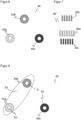
- Figure 6 shows a top view
- Figure 7 shows a side view of an alternative multi-part intermediate piece 46.
- these are the support points 50a-c of the Figures 4 to 5 , but without connecting material for a common intermediate piece 46.
- Such an intermediate piece 46 uses less material.
- a multi-part intermediate piece 46 should be attached to the laser scanner 10 before the laser scanner 10 is delivered to the operating site. Arranging a loose multi-part intermediate piece 46 between the first outer wall 42 and the flat base surface 44 only during assembly further increases the risk of confusion.
- Figure 8 shows a top view of another multi-part compensating intermediate piece 46.
- two support points 50a-b are assembled on a common component 53, only the third support point 50c forms a separate component.
- This is a hybrid form in which the advantages and disadvantages of a common component are taken into account in accordance with the Figures 4 and 5 and a multi-part component according to the Figures 6 and 7 appear in a weaker form each time.
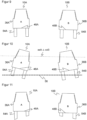
- the Figures 9 to 11 show another embodiment of the alignment of a laser scanner 10 by an individual compensating three-dimensional contour.
- Legs 54A-B with an oversize or excess length and thus a kind of material reserve are attached to the inner housing wall 48A-B. These legs 54A-B are therefore firmly connected to the laser scanner 10 at the beginning or in an early phase of production before individual adjustment.
- the first outer wall 42 is formed in this embodiment by the inner housing wall 48A-B and the legs 54A-B.
- the individual detection direction and/or individual detection height are measured, for example during final production.
- the legs 54A-B are now shortened in a mechanical rework according to the parting plane 56 shown, for example by a machining process or laser ablation.
- the parting plane 56 is merely an illustration of the required shortening and thus the three-dimensional contour to be achieved.
- the laser scanners 10A-B will assume the required alignment at the operating location with respect to a flat base surface 44 corresponding to the parting plane 56.
- Figure 11 shows the two laser scanners 10A-B once again in the delivery state. An intermediate piece 46 is not required in this embodiment.
- the Figure 12 illustrates another embodiment of the alignment, wherein Figure 13 a detailed view of the Figure 12 with the circle 58.
- the three-dimensional contour with support points of different heights is achieved by pressing pins 60 to different depths into a recess 62 in the inner housing wall 48.
- the pins 60 preferably originally have the same length, so they can be identical to one another, although pins of different lengths can also be used alternatively.
- the recess 62 can be dispensed with.
- the pins 60 can also be fixed at the correct depth, for example by gluing or welding.
- Figure 14 illustrates a very similar embodiment of the alignment, where Figure 15 a detailed view of the Figure 14 with the cutout marked with the circle 58.
- Threaded bushings 64 are pressed into the inner housing wall 48 at different depths. This also illustrates that pins 60 as well as threaded bushings 64 serve only as examples of elements that can be inserted at different depths in order to effectively produce different heights of the support points.
Landscapes
- Engineering & Computer Science (AREA)
- Physics & Mathematics (AREA)
- General Physics & Mathematics (AREA)
- Computer Networks & Wireless Communication (AREA)
- Radar, Positioning & Navigation (AREA)
- Remote Sensing (AREA)
- Computer Vision & Pattern Recognition (AREA)
- Electromagnetism (AREA)
- Measurement Of Optical Distance (AREA)
- Length Measuring Devices By Optical Means (AREA)
Abstract
Description
- Die Erfindung betrifft ein Sensormodul für einen Sensor, insbesondere ein optoelektronisches Sensormodul für einen optoelektronischen Sensor, und ein Verfahren zur Herstellung eines ausgerichteten Sensormoduls nach dem Oberbegriff von Anspruch 1 beziehungsweise 9.
- Es gibt Sensoren, die auf vielfältigsten Sensorprinzipien basieren und die an ihrem Betriebsort einer Ausrichtung bedürfen. Im Folgenden werden optische Erfassungsprinzipien als Beispiel herangezogen, bei denen die Ausrichtung regelmäßig besonders präzise sein muss. Ein verbreiteter optoelektronischer Sensor ist der Laserscanner, der sich für Erfassungen und Abstandsmessungen eignet, die einen großen horizontalen Winkelbereich des Messsystems erforderlich machen. In einem Laserscanner überstreicht ein von einem Laser erzeugter Lichtstrahl mit Hilfe einer Ablenkeinheit periodisch einen Überwachungsbereich. Das Licht wird an Objekten in dem Überwachungsbereich remittiert und in dem Laserscanner ausgewertet. Aus der Winkelstellung der Ablenkeinheit wird auf die Winkellage des Objektes und aus der Lichtlaufzeit unter Verwendung der Lichtgeschwindigkeit in einem Phasen- oder Pulsverfahren zusätzlich auf die Entfernung des Objektes von dem Laserscanner geschlossen. Mit den Winkel- und Entfernungsangaben ist der Ort eines Objektes in dem Überwachungsbereich in zweidimensionalen Polarkoordinaten erfasst. Damit lassen sich die Positionen von Objekten ermitteln oder deren Kontur bestimmen.
- Neben solchen Messanwendungen werden Laserscanner auch in der Sicherheitstechnik zur Überwachung einer Gefahrenquelle eingesetzt, wie sie beispielsweise eine gefährliche Maschine darstellt. Ein derartiger Sicherheitslaserscanner ist aus der
DE 43 40 756 A1 bekannt. Dabei wird ein Schutzfeld überwacht, das während des Betriebs der Maschine vom Bedienpersonal nicht betreten werden darf. Erkennt der Laserscanner einen unzulässigen Schutzfeldeingriff, etwa ein Bein einer Bedienperson, so löst er einen Nothalt der Maschine aus. In der Sicherheitstechnik eingesetzte Sensoren müssen besonders zuverlässig arbeiten und deshalb hohe Sicherheitsanforderungen erfüllen, beispielsweise die Norm EN13849 für Maschinensicherheit und die Gerätenorm EN61496 für berührungslos wirkende Schutzeinrichtungen (BWS). - Laserscanner sind aus einer Vielzahl von toleranzbehaften Einzelteilen aufgebaut. Infolgedessen ergeben sich Fertigungsschwankungen für Lichtaustritt und Scanebene: Die Höhe und Ausrichtung der Scanebene variieren in gewissem Rahmen von Gerät zu Gerät. Aus Kostengründen ist es nicht immer möglich, die Toleranzen in dem Laserscanner von vorneherein so klein zu halten, dass die individuellen Schwankungen nicht stören. Das macht in den meisten Anwendungen eine händische Ausrichtung bei der Installation erforderlich. Bei einem späteren Austausch des Laserscanners muss die Ausrichtung wiederholt werden. Zudem sind Halterungen notwendig, die überhaupt eine Ausrichtung ermöglichen. Solche Halterungen sind teuer und benötigen zusätzlichen Bauraum.
- Es ist bekannt, ein Gerät mit Füßchen zu versehen, die in ihrer Höhe verstellbar sind. Das ist aber nur ein Beispiel für eine soeben genannte Halterung, die eine Ausrichtung ermöglicht. Das Ausrichten selbst ist damit nicht vollzogen, und solche Füßchen bergen immer die Gefahr, dass durch gewollte oder ungewollte Manipulation im Laufe des Betriebs die Ausrichtung verloren geht.
- Die
DE 20 2015 106 370 U1 offenbart ein weiteres Beispiel einer Halterung zum Ausrichten eines Laserscanners. Mittels einer Verzahnung zweier Halterungsteile kann der bereits montierte Laserscanner noch verdreht werden. Aus derEP 1 852 646 A2 und derUS 2009/294619 A1 sind jeweils einstellbare Halterungen für einen Projektor bekannt. Mit keiner dieser Halterungen sind die oben genannten Nachteile überwunden. - Es ist daher Aufgabe der Erfindung, die Ausrichtung eines Sensors zu verbessern.
- Diese Aufgabe wird durch ein Sensormodul für einen Sensor, insbesondere ein optoelektronisches Sensormodul für einen optoelektronischen Sensor, und ein Verfahren zur Herstellung eines ausgerichteten Sensormoduls nach Anspruch 1 beziehungsweise 9 gelöst. Als Sensormodul wird eine Baugruppe bezeichnet, in der die eigentlichen Sensorelemente zusammengefasst sind. Es kann sich hier beispielsweise um eine Sende-Empfangsbaugruppe für die Sensorsignale handeln. Das Sensormodul umfasst eine Sensoreinheit. Das ist nun der funktionale Kern des Sensormoduls, wobei der genauere Aufbau vom jeweiligen Sensorprinzip und Sensortyp abhängt. Bei einem optoelektronischen Sensor kann die Sensoreinheit beispielsweise einen Bildsensor oder einen einfacheren Lichtempfänger aufweisen, möglicherweise kombiniert mit einem Lichtsender Die Sensoreinheit hat eine Erfassungsrichtung und eine Erfassungshöhe, mit denen sich die Ausrichtung charakterisieren lässt. Bei einem optoelektronischen Sensor entspricht das beispielsweise der Orientierung der optischen Achse und der Höhe ihres Durchstoßpunktes aus dem Sensor beziehungsweise in den Sensor. Bei einer Kamera wird damit beschrieben, auf welcher Höhe ihr Sichtfeld liegt und wie es ausgerichtet ist. Bei einem aktiven optoelektronischen Sensor, etwa einem Lichttaster, beschreiben die beiden Grö-ßen die Orientierung des Abtaststrahls und die Höhe des Lichtaustritts bezüglich des Sensors.
- Das Sensormodul umfasst weiterhin ein Modulgehäuse, in dem sich die Sensoreinheit befindet. Der Begriff Modulgehäuse ist erst einmal weit zu verstehen. Erfindungsgemäß kommt es auf eine erste Außenwand des Modulgehäuses an, die beispielsweise lediglich als Sockel ausgebildet sein kann. Lediglich vorzugsweise umfasst das Modulgehäuse weitere Gehäuse- oder Außenwände, die es zu einem Gehäuse im engeren Sinne machen und die vorzugsweise die Sensoreinheit von allen Seiten umschließen. Es ist denkbar, dass zusätzlich zu der ersten Außenwand mindestens eine weitere Außenwand deren Rolle einnehmen kann, etwa wenn das Sensormodul wahlweise nach rechts oder links an einer Wand oder in einem Umgehäuse montiert oder beispielsweise auf den Kopf gestellt werden kann.
- Durch Anordnung der ersten Außenwand an einer ebenen Grundfläche werden die Orientierung und Höhenposition des Modulgehäuses und damit die Erfassungsrichtung und Erfassungshöhe der Sensoreinheit festgelegt. Die ebene Grundfläche ist je nach Ausführungsform diejenige eines Umgehäuses oder einer Montage- beziehungsweise Aufstellumgebung. Beispielsweise wird das Sensormodul mit der ersten Außenwand als Bezugsfläche an einer beliebigen Wand des Umgehäuses angeordnet, vorzugsweise unten. Oder es wird selbst, ohne Umgehäuse, mit der ersten Außenwand als Unterseite auf den Boden oder einen Werktisch gestellt oder mit der ersten Außenwand als Rückwand oder Seitenwand an einer Wand montiert. In diesem Zusammenhang ist darauf hinzuweisen, dass Begriffe wie Höhe und Erfassungshöhe sich an eine aufrechte Orientierung des Sensors mit horizontaler ebener Grundfläche anlehnen, bei seitlicher Montage ist die Höhe als seitlicher Abstand zu der dann vertikalen ebenen Grundfläche aufzufassen, und entsprechend bei beliebigen anderen Orientierungen des Sensors und der ebenen Grundfläche.
- Die Erfindung geht von dem Grundgedanken aus, der ersten Außenwand eine dreidimensionale Kontur zu geben, die bei Anordnung an der ebenen Grundfläche die individuelle Erfassungsrichtung und/oder Erfassungshöhe der Sensoreinheit korrigiert. Die erste Außenwand hat, um ihre Funktion als Außenwand zu erfüllen, eine flächige Ausdehnung. Die dreidimensionale Kontur bezieht eine dritte Dimension senkrecht zu der flächigen Ausdehnung ein, die als Höhe oder Dicke bezeichnet werden kann. Lokale Anteile der dreidimensionalen Kontur sorgen für einen Ausgleich der Erfassungsrichtung, und ihre Gesamtdicke sorgt für einen Ausgleich der Erfassungshöhe. Für die Ausgleichsfunktion relevant sind dabei nur die Kontaktpunkte und/oder Kontaktflächen zwischen erster Außenwand und ebener Grundfläche, dazwischen ist die dreidimensionale Kontur letztlich beliebig und kann beispielsweise kleinere oder größere Aussparungen aufweisen. Es sind demnach Ausführungsformen mit vollflächigem Kontakt, nur wenigen Auflagepunkten, vorzugsweise drei Auflagepunkten, und beliebige Mischformen mit flächigem und/oder punktuellem Kontakt denkbar. Die dreidimensionale Kontur korrigiert je nach Ausführungsform nur die Erfassungsrichtung, nur die Erfassungshöhe oder beides.
- Aufgrund von Fertigungstoleranzen weist jedes Sensormodul eine individuelle Erfassungsrichtung und Erfassungshöhe auf. Um dies auszugleichen, ergibt sich eine entsprechende individuelle dreidimensionale Kontur mit einer Abweichung von einer herkömmlichen, ebenen Außenwand in Form und/oder Dicke. Insbesondere ist die dreidimensionale Kontur invers zu den individuellen Abweichungen von einer spezifizierten Erfassungsrichtung und/oder Erfassungshöhe geformt. Ist beispielsweise die Sensoreinheit in ihrem Gehäuse nach links geneigt, wird vorzugsweise die erste Außenwand im gleichen Maße links erhöht, um die Sensoreinheit in die in diesem Beispiel spezifizierte Horizontale zu bringen, entsprechend nach rechts beziehungsweise oben und unten für die Vertikale. Zum Höhenausgleich ist die Dicke oder Höhe der ersten Außenwand insgesamt um so viel vermindert oder vergrößert, wie die individuelle Erfassungshöhe nach oben oder unten von einer spezifizierten Erfassungshöhe abweicht.
- Die dreidimensionale Kontur des Sensormoduls ist für das Sensormodul festgelegt und nicht für eine weitere Veränderung ausgebildet. Es handelt sich also nicht um Stellschrauben oder dergleichen, sondern die dreidimensionale Kontur ist eine festgelegte Eigenschaft der ersten Außenwand. Natürlich kann dennoch mit entsprechendem Werkzeug auf die dreidimensionale Kontur eingewirkt werden, aber das ist ein zerstörender Fehlgebrauch und damit keine vorgesehene Eigenschaft des Sensormoduls.
- Die Erfindung hat den Vorteil, dass die Ausrichtung eines Sensors bei der Installation automatisch gewährleistet ist. Dabei ist der Installationsaufwand verringert, und das Ausrichtergebnis ist garantiert. Individuelle Unterschiede innerhalb einer Produktfamilie sind ausgeglichen, beispielsweise tasten alle Laserscanner einer Produktfamilie eine gleiche Scanebene ab. Verstellbare Justagehalter sind nicht mehr erforderlich. Im Falle eines Sensortauschs bedarf es nicht länger einer neuen Ausrichtung, das neue Gerät nimmt nach dem Prinzip "Plug & Play" die Rolle seines Vorgängers ein.
- Das Modulgehäuse ist bevorzugt in einem Sensorgehäuse des Sensors angeordnet, wobei die ebene Grundfläche eine Wand des Sensorgehäuses oder damit fest verbunden ist. Das greift das schon erwähnte Beispiel der Anordnung in einem Umgehäuse auf. Die ebene Grundfläche muss nicht selbst eine Wand des Sensorgehäuses sein, es genügt, wenn sie in fester Lage damit verbunden ist. In dem Umgehäuse können weitere Komponenten des Sensors untergebracht sein, wie Auswertungselektronik, eine Versorgung oder Kommunikationsschnittstellen. Aufgrund der Erfindung kann das Sensormodul als hochgenaue Einheit in dem Umgehäuse und damit dem vollständigen Sensor montiert werden. Der Sensor ist dann in sich ausgerichtet, die einleitend diskutierten Toleranzen sind ausgeglichen.
- Das Sensormodul ist alternativ bereits selbst der Sensor, wobei das Modulgehäuse zugleich als Sensorgehäuse fungiert. Das Sensormodul ist in diesem Ausführungsbeispiel mit dem Sensor identisch. Dementsprechend gibt es kein zusätzliches Umgehäuse, obwohl natürlich niemand gehindert ist, einen vollständigen Sensor nochmals in ein Umgehäuse zu stellen. Die erste Außenwand mit ihrer dreidimensionalen Kontur sorgt dafür, dass der Sensor bei Aufstellen auf die ebene Grundfläche oder Montage an der ebenen Grundfläche ausgerichtet ist.
- Der Sensor ist bevorzugt ein Laserscanner oder ein Radar mit mindestens einer Scanebene, deren Orientierung durch die Erfassungsrichtung festgelegt ist. In diesem Fall ist die dreidimensionale Kontur sehr intuitiv zu verstehen: Sie reproduziert eine Schieflage der Scanebene in invertierter Form als ebenfalls schiefe Ebene, wobei die dreidimensionale Kontur wie erwähnt nicht vollflächig sein muss. In einem Laserscanner erzeugt, wie einleitend schon skizziert, ein Lichtsender Sendelicht und sendet es in den Überwachungsbereich aus. Das Sendelicht wird als remittiertes Sendelicht wieder empfangen, nachdem es zumindest teilweise im Überwachungsbereich von einem Objekt zurückgeworfen wurde. Bevorzugt ist eine Steuer- und Auswertungseinheit dafür ausgebildet, aus einer Lichtlaufzeit zwischen Aussenden des Sendelichts und Empfangen des Empfangslichts einen Abstand des Objekts zu bestimmen. Mit Hilfe einer beweglichen Ablenkeinheit wird eine Scanbewegung erzeugt, vorzugsweise eine Drehbewegung, mit der das Sendelicht und das Empfangslicht periodisch in unterschiedliche Ablenkwinkel ausgesandt beziehungsweise aus unterschiedlichen Ablenkwinkeln erfasst wird. Dadurch wird die Scanebene abgetastet. Es gibt Mehrlagenscanner, die mehrere Sender-/Empfängerpaare aufweisen und so mehrere Scanebenen abtasten, dann bezieht sich Erfassungsrichtung auf eine ausgewählte der Scanebenen. Ein Radar funktioniert auf dieser abstrakten Beschreibungsebene genauso, wobei statt Licht Radarsignale erzeugt und empfangen werden.
- Die erste Außenwand ist bevorzugt in das Modulgehäuse integriert. Die erste Außenwand ist also insgesamt integraler Bestandteil des Modulgehäuses. Ohne die erste Außenwand wäre das Modulgehäuse an dieser Seite offen. Dies ist als Alternative zu einem sogleich vorzustellenden Zwischenstück zu verstehen.
- Die erste Außenwand weist bevorzugt eine innere Gehäusewand und ein daran angeordnetes Zwischenstück auf. Das Zwischenstück wird zwischen innerer Gehäusewand und ebener Grundfläche angeordnet. Die innere Gehäusewand ist bevorzugt so ausgebildet wie bei einem herkömmlichen Gehäuse, also eben und von zum übrigen Modulgehäuse gleichmäßiger Dicke. Das Zwischenstück weist dann die dreidimensionale Kontur auf. Alternativ ist denkbar, dass die innere Gehäusewand mit zu der dreidimensionalen Kontur beiträgt.
- Das Zwischenstück ist bevorzugt einteilig ausgebildet. Beispielsweise handelt es sich um ein Montageblech. Ein solches Zwischenstück ist kostengünstig herstellbar und einfach zu handhaben.
- Das Zwischenstück ist bevorzugt mit der inneren Gehäusewand verbunden und mehrteilig ausgebildet, insbesondere als mehrere gleichartige Stifte, Scheiben oder Gewindebuchsen, die unterschiedlich weit in die innere Gehäusewand eingebracht sind. Ein solches Zwischenstück wird also nicht erst am Montageort mit der inneren Gehäusewand in Kontakt gebracht, sondern ist bereits daran befestigt. Prinzipiell wären auch lose Teile denkbar, wie Unterlegscheiben, aber dies ist schlechter zu handhaben und birgt eine Verwechslungsgefahr, mit der die Ausrichtung doch nicht erzielt wird. Das Zwischenstück kann für jeden Auflagepunkt, vorzugsweise drei Auflagepunkte, ein eigenes Teil aufweisen. Jedes dieser Teile kann eine individuelle Höhe aufweisen oder auf eine individuelle Höhe gekürzt sein. Bevorzugt sind die Teile untereinander gleichartig und für eine unterschiedliche effektive Höhe der zugehörigen Auflagepunkte unterschiedlich tief in die innere Gehäusewand beziehungsweise des Modulgehäuses eingebracht. Es ist denkbar, zwei oder mehr Auflagepunkte in einem Teil zusammenzufassen, beispielsweise ein langgestrecktes Teil mit zwei Auflagepunkten und ein kleines weiteres Teil mit dem dritten Auflagepunkt zu verwenden.
- Das Zwischenstück ist bevorzugt durch mechanische Verschränkung, Form, Einpressen, Magnetkraft, Schrauben, Kleben oder Schweißen mit der inneren Gehäusewand verbunden. Für eine mechanische Verbindung können Haken oder ein Rastmechanismus vorgesehen sein, oder durch Passung entsteht eine formschlüssige Verbindung. Andere Verbindungen, wie durch Magnete, Schrauben, Bolzen, Kleben oder Schweißen sind ebenfalls möglich.
- Das Zwischenstück ist bevorzugt mit einer Materialabtragung bearbeitet. Damit wird die dreidimensionale Kontur einem entsprechenden Rohling sozusagen negativ aufgeprägt. Umgekehrt ist ein additives Verfahren oder ein 3D-Druck vorstellbar, mit dem ein Zwischenstück mit der vorgesehenen dreidimensionalen Kontur hergestellt wird. Mit einem additiven Verfahren kann im Übrigen die dreidimensionale Kontur auch direkt auf die Außenwand gedruckt werden und ist dann damit verbunden. Das kann man wahlweise so verstehen, dass die Außenwand dann die Rolle der Innenwand einnimmt und der Aufdruck diejenige des Zwischenstücks, oder dass die Außenwand samt dreidimensionaler Kontur eine in das Gehäuse integrierte Außenwand ohne Zwischenstück ist.
- Bei dem erfindungsgemäßen Verfahren zur Herstellung eines ausgerichteten Sensormoduls für einen Sensor wird zunächst eine Sensoreinheit hergestellt und mit der sich dabei aus Bauteil-, Einbau- oder sonstigen Toleranzen ergebenden individuellen Erfassungsrichtung und Erfassungshöhe in ein Modulgehäuse mit mindestens einer ersten Außenwand eingebaut. Das Gerät wird dann mit der ersten Außenwand an einer ebenen Grundfläche angeordnet, und die individuelle Erfassungsrichtung und/oder die individuelle Erfassungshöhe wird vermessen, um daraus eine Abweichung von einer spezifizierten oder gewünschten Erfassungsrichtung beziehungsweise Erfassungshöhe zu bestimmen. Die erste Außenwand wird dann mit einer dreidimensionalen Kontur versehen, die die Abweichungen ausgleicht.
- Das Modulgehäuse wird bevorzugt in einem Sensorgehäuse auf einer Wand des Sensorgehäuses oder einer damit fest verbundenen Bezugsfläche angeordnet, die die ebene Grundfläche bildet. Es entsteht damit ein in sich hochgenau ausgerichteter Sensor. Alternativ ist das Sensormodul bereits der Sensor, und das Modulgehäuse fungiert zugleich als Sensorgehäuse, so dass mit dem Sensormodul bereits der Sensor hergestellt ist.
- Die erste Außenwand wird bevorzugt mit dem Modulgehäuse und vollständig als Teil des Modulgehäuses hergestellt. Dabei weist die erste Außenwand insbesondere zunächst einen Materialzuschlag oder Materialüberschuss auf, der dann teilweise entfernt wird, um die dreidimensionale Kontur herzustellen. Der Materialzuschlag muss sich nicht über die gesamte erste Außenwand erstrecken, es können auch lediglich mehrere Säulen, Beinchen oder Stifte vorgesehen sein, die individuell eingekürzt werden, um die dreidimensionale Kontur mit entsprechenden Kontaktpunkten herzustellen.
- Das Modulgehäuse wird bevorzugt zunächst mit einer inneren Gehäusewand hergestellt, es wird ein Zwischenstück mit der dreidimensionalen Kontur hergestellt, und das Zwischenstück wird an der inneren Gehäusewand befestigt oder zwischen innerer Gehäusewand und ebener Grundfläche angeordnet, so dass innere Gehäusewand und Zwischenstück gemeinsam die erste Außenwand bilden. Das Zwischenstück kann also wahlweise schon während der Fertigung mit dem Modulgehäuse verbunden oder zunächst lose bleiben und erst am Betriebsort untergelegt oder zwischengelegt werden. Ein Zwischenstück hat den Vorteil, dass der Sensor selbst unverändert bleiben kann und lediglich ein kostengünstiges Zwischenstück ergänzt wird.
- Das Zwischenstück wird vorzugsweise durch Materialabtragung aus einem Rohling hergestellt. Dabei wird die dreidimensionale Kontur aus dem Rohling herausgearbeitet, beispielsweise einem Montageblech. Alternativ wird das Zwischenstück durch ein additives Verfahren beziehungsweise einen 3D-Druck einschließlich der dreidimensionalen Kontur hergestellt.
- Das Zwischenstück wird vorzugsweise mit einer Markierung versehen, aus der die Zugehörigkeit zu dem Sensor hervorgeht. Das ist vor allem in einer Ausführungsform von Nutzen, in der das Zwischenstück zunächst lose bleibt. Durch die Markierung kann auf einfache Weise eine eindeutige Zuordnung des Zwischenstücks zu demjenigen Sensor vorgenommen werden, für den es mit seiner dreidimensionalen Kontur hergestellt wurde. Beispielsweise eignet sich dafür eine Seriennummer des Sensors, die sich ohnehin in aller Regel am Modulgehäuse oder zumindest in den zugehörigen Unterlagen des Sensors befindet. Die Markierung kann direkt auf dem Zwischenstück aufgebracht werden, beispielsweise mit Laserbeschriftung, es ist aber beispielsweise auch ein Druck auf ein Klebeetikett oder dergleichen denkbar.
- Das Zwischenstück weist bevorzugt eine Markierung und/oder Strukturierung auf, anhand derer es in der richtigen Orientierung angebracht wird. Das Zwischenstück ist typischerweise nicht symmetrisch, das ist ja gerade dessen Zweck. Es bedarf also im Falle eines zunächst lose bleibenden Zwischenstücks, ebenso bei der Anbringung des Zwischenstücks im Rahmen der Fertigung, einer korrekten Orientierung. Dafür können bestimmte Seiten des Zwischenstücks farbig oder mit Symbolen markiert sein. Denkbar ist auch eine Grundform, die eine eindeutige Orientierung erkennen lässt. Möglich sind auch Strukturierungen auf der vorgesehenen Verbindungsseite des Zwischenstücks und der inneren Gehäusewand in einem Muster, das nur in passender Orientierung zu einem gegenseitigen Eingriff führt. Die Markierung beziehungsweise Strukturierung kann bereits der Rohling tragen, sie muss im Gegensatz zu der Markierung des Vorabsatzes nicht individuell sein. Vielmehr wird die dreidimensionale Kontur dann passend zur vorgegebenen Orientierung hergestellt.
- Das Zwischenstück weist vorzugsweise mehrere untereinander gleichartige Teile auf, die in unterschiedliche Tiefen in die innere Gehäusewand eingebracht werden. Beispiele dafür sind Stifte oder Gewindebuchsen, die so tief eingebracht werden, dass der Überstand die gewünschte dreidimensionale Kontur ergibt. Alternativ ist denkbar, mehrere Teile mit unterschiedlichen Dicken oder Längen herzustellen oder vorzuhalten und eine passende Auswahl mit der inneren Gehäusewand zu verbinden. Nochmals alternativ können mehrere Teile lose bleiben, aber das ist nicht benutzerfreundlich und fehleranfällig.
- Zu weiteren möglichen Herstellungsschritten und den Vorteilen, die sich aus dem dadurch hergestellten Sensor ergeben, wird ergänzend auf die Ausführungen zu dem erfindungsgemäßen Sensor verwiesen.
- Die Erfindung wird nachstehend auch hinsichtlich weiterer Merkmale und Vorteile beispielhaft anhand von Ausführungsformen und unter Bezug auf die beigefügte Zeichnung näher erläutert. Die Abbildungen der Zeichnung zeigen in:
- Fig. 1
- eine schematische Darstellung eines Laserscanners;
- Fig. 2
- eine schematische Darstellung eines Laserscanners mit Veranschaulichung verschiedener möglicher Scanebenen aufgrund von Fertigungstoleranzen;
- Fig. 3
- eine schematische Darstellung zweier Laserscanner jeweils mit einem individuellen Zwischenstück zum Ausgleich der sich durch Fertigungstoleranzen ergebenden Fehlausrichtungen;
- Fig. 4
- eine Draufsicht auf ein beispielhaftes ausgleichendes Zwischenstück;
- Fig. 5
- eine Seitenansicht zu
Figur 4 ; - Fig. 6
- eine Draufsicht auf ein beispielhaftes mehrteiliges ausgleichendes Zwischenstück;
- Fig. 7
- eine Seitenansicht zu
Figur 6 ; - Fig. 8
- eine Draufsicht auf ein weiteres mehrteiliges ausgleichendes Zwischenstück;
- Fig. 9
- eine schematische Darstellung zweier Laserscanner mit individuellen Fertigungstoleranzen in einer Ausgangssituation mit langen, noch nicht angepassten Beinchen;
- Fig. 10
- eine Darstellung entsprechend
Figur 9 mit einer jeweiligen die individuellen Fertigungstoleranzen ausgleichenden Ausrichtung der beiden Laserscanner; - Fig. 11
- eine Darstellung entsprechend
Figur 10 der beiden Laserscanner mit entsprechend der erforderlichen ausgleichenden Ausrichtung individuell eingekürzten Beinchen; - Fig. 12
- eine schematische Darstellung eines Laserscanners mit Stiften, die zum Ausrichten unterschiedlich tief eingepresst sind;
- Fig. 13
- eine Detailansicht der
Figur 12 des Bereichs mit einem eingepressten Stift; - Fig. 14
- eine schematische Darstellung eines Laserscanners mit Gewindebuchsen, die zum Ausrichten unterschiedlich tief eingepresst sind; und
- Fig. 15
- eine Detailansicht der
Figur 14 des Bereichs mit einer eingepressten Gewindebuchse. -
Figur 1 zeigt eine schematische Schnittdarstellung durch einen Laserscanner 10. Ein Lichtsender 12, beispielsweise mit einer Laserlichtquelle, erzeugt mit Hilfe einer Sendeoptik 14 einen Sendelichtstrahl 16. Der Sendelichtstrahl 16 wird mittels einer Ablenkeinheit 18 in einen Überwachungsbereich 20 ausgesandt. Zur Vermeidung optischen Übersprechens kann der Sendelichtstrahl 16 zumindest teilweise von einem nicht gezeigten Sendetubus umgeben sein. - Im Überwachungsbereich 20 wird der Sendelichtstrahl 16 von einem gegebenenfalls vorhandenen Objekt remittiert. Das entsprechende Empfangslicht 22 gelangt wieder zu dem Laserscanner 10 zurück und wird über die Ablenkeinheit 18 mittels einer Empfangsoptik 24 von einem Lichtempfänger 26 detektiert. Die Empfangsoptik 24 ist vorzugsweise eine einzelne Sammellinse, es können aber weitere Linsen und sonstige optische Elemente hinzukommen. Der Lichtempfänger 26 weist beispielsweise mindestens eine Photodiode oder für höhere Empfindlichkeit eine Lawinenphotodiode (APD) beziehungsweise eine Anordnung mit mindestens einer Einzelphotonlawinendiode (SPAD, SiPM) auf.
- Die Ablenkeinheit 18 wird von einem Motor 28 in eine kontinuierliche Drehbewegung mit einer Scanfrequenz versetzt. Dadurch tastet der Sendelichtstrahl 16 während jeder Scanperiode, also einer vollständigen Umdrehung bei der Scanfrequenz, eine Ebene ab. Am Außenumfang der Ablenkeinheit 18 ist eine Winkelmesseinheit 30 angeordnet, um die jeweilige Winkelstellung der Ablenkeinheit 18 zu erfassen. Die Winkelmesseinheit 30 wird hier beispielhaft von einer Strichscheibe als Winkelmaßverkörperung und einer Gabellichtschranke als Abtastung gebildet.
- Eine Steuer- und Auswertungseinheit 32 ist mit dem Lichtsender 12, dem Lichtempfänger 26, dem Motor 28 und der Winkelmesseinheit 30 verbunden. Durch Bestimmen der Lichtlaufzeit zwischen Aussenden des Sendelichtstrahls 16 und Empfang von remittiertem Empfangslicht 22 wird unter Verwendung der Lichtgeschwindigkeit auf die Entfernung eines angetasteten Objektes von dem Laserscanner 10 geschlossen. Die jeweilige Winkelstellung, unter welcher dabei der Sendelichtstrahl 16 ausgesandt wurde, ist der Auswertungseinheit von der Winkelmesseinheit 30 bekannt.
- Somit stehen nach jeder Scanperiode über den Winkel und die Entfernung zweidimensionale Polarkoordinaten der Objektpunkte in dem Überwachungsbereich 20 zur Verfügung, und entsprechende Messdaten können über eine Schnittstelle 34 übertragen werden. Die Schnittstelle 34 kann umgekehrt für eine Parametrierung oder sonstigen Datenaustausch zwischen Laserscanner 10 und Außenwelt genutzt werden. Die Schnittstelle 34 kann für die Kommunikation in einem oder mehreren herkömmlichen Protokollen ausgelegt sein, wie IO-Link, Ethernet, Profibus, USB3, Bluetooth, WLAN, LTE, 5G und vielen weiteren. Bei Anwendungen in der Sicherheitstechnik kann die Schnittstelle 34 sicher ausgebildet, insbesondere ein sicherer Ausgang (OSSD, Output Signal Switching Device) für ein sicherheitsgerichtetes Abschaltsignal bei Erkennen einer Schutzfeldverletzung sein. Der Laserscanner 10 ist in einem Gehäuse 36 untergebracht, welches eine umlaufende Frontscheibe 38 aufweist.
- Bei dem dargestellten Laserscanner 10 befindet sich der Lichtsender 12 und dessen Sendeoptik 14 in einer zentralen Öffnung der Empfangsoptik 24. Dies ist nur eine beispielhafte Möglichkeit der Anordnung. Die Erfindung umfasst daneben alternative koaxiale Lösungen, etwa mit einem eigenen Spiegelbereich für den Sendelichtstrahl 16 oder mit Teilerspiegeln, und auch biaxiale Anordnungen. Weiterhin kann der Laserscanner 10 als Ablenkeinheit anstelle eines Drehspiegels einen drehenden Messkopf verwenden, in dem Lichtsender 12 und/oder Lichtempfänger 26 rotieren. Nochmals andere Bauformen eines Laserscanners 10 tasten nicht nur eine einzige Scanebene ab, sondern sind mehrstrahlig und damit als Mehrlagenscanner ausgebildet. Für die sogleich zu erläuternde Ausrichtung wird dann eine der mehreren Scanebenen herangezogen, insbesondere soweit vorhanden eine zentrale Scanebene. Ein Mehrlagenscanner weist mehrere in Elevation zueinander versetzt wirkende Sender-/Empfängerpaare auf, wobei mehrere Lichtstrahlen beispielsweise mittels Strahlteilern oder als VCSEL-Array von einer Lichtquelle erzeugt und/oder in einem Matrix- oder speziell SPAD-Array empfangen werden können.
- Die Erfindung wird stellvertretend anhand eines Laserscanners 10 beschrieben. Sie umfasst aber auch andere optoelektronische Sensoren, beispielsweise einen Lichttaster, dessen Abtaststrahl auszurichten ist, ein Lichtgitter mit einer Vielzahl zueinander paralleler Erfassungsstrahlen oder eine 2D- beziehungsweise 3D-Kamera mit Ausrichtung ihres Sichtfeldes. Ferner sind Sensoren umfasst, die kein optisches Sensorprinzip verwenden. Dabei ist zunächst ein Radar zu erwähnen, das ebenfalls eine Scanebene abtastet, auch wenn diese womöglich in Elevation etwas weniger scharf abgegrenzt ist. Weitere nicht abschließend genannte Sensoren sind Ultraschallsensoren, kapazitive, induktive oder magnetische Sensoren, die alle je nach Bauform und Anwendung einer mehr oder weniger präzisen Ausrichtung bedürfen. Der erfindungsgemäße Sensor kann als Sicherheitssensor im Sinne der einleitend genannten Normen ausgebildet sein, insbesondere als Sicherheitslaserscanner, und in der Sicherheitstechnik zur Unfallvermeidung beispielsweise durch Überwachung von Schutzfeldern oder Bewertung von Abstand und Geschwindigkeit eines Objekts im Umfeld einer Gefahrenquelle (Speed-and-Separation) eingesetzt sein.
- Der Laserscanner 10 der
Figur 1 ist ein vollständiger Sensor, und an diesem Beispiel wird im Folgenden die Ausrichtung mit dessen Gehäuse 36 gegenüber Außen, insbesondere einer Aufstellfläche, Wand oder dergleichen erläutert. Die Erfindung kann zudem so angewandt werden, dass damit ein Sensormodul wie beispielsweise eine Empfängerbaugruppe oder eine Sende-Empfängerbaugruppe hochgenau ausgerichtet in einem Sensorgehäuse montiert wird. Die Bezugsfläche ist dann nicht außen, sondern eine Wand oder eine damit verbundene Referenzfläche des Sensorgehäuses. Das Ausrichtprinzip in allen Varianten ist das gleiche, somit analog übertragbar, und wird deshalb nicht eigens beschrieben. -
Figur 2 zeigt eine schematische Darstellung eines Laserscanners 10 mit Veranschaulichung zweier verschiedener Scanebenen 40A-B aufgrund von Fertigungstoleranzen. Von einem Laserscanner 10 werden im Folgenden nur noch die Außenkonturen gezeigt, für die weiteren Elemente wird auf die Erläuterungen zuFigur 1 verwiesen. Der Laserscanner 10 ist mit einer ersten Außenwand 42 an einer ebenen Grundfläche 44 angeordnet. InFigur 2 ist das so dargestellt, dass der Laserscanner 10 mit seiner Unterseite auf dem Boden steht. Es kann ebenso eine beliebige andere Seite des Laserscanners 10 an einer beliebig anders orientierten Grundfläche 44 angeordnet sein, beispielsweise bei Montage mit der Unterseite an der Wand oder mit der Oberseite an der Decke. Mit erster Außenwand 42 ist diejenige gemeint, die in Kontakt mit der ebenen Grundfläche 44 kommt. - Die Scanebene 40A-B verläuft in jedem Laserscanner 10 als Folge von Bauteil-, Einbau- oder sonstigen Toleranzen etwas anders, wobei
Figur 2 dies deutlich übertrieben darstellt. Dies wird durch zwei Größen erfasst. Das ist zum einen die Orientierung, die durch eine Erfassungsrichtung charakterisiert wird. Denn die Neigung der Scanebene 40A-B ergibt sich aus der Abstrahlrichtung des Sendelichtstrahls 16. Dies wird beispielsweise als Winkel αA, αB zur Grundebene 44 angegeben. Zum anderen ist es eine Erfassungshöhe hA, hB, die vom Lichtaustrittsbereich gegen eine Referenz wie den unteren Geräteabschluss gemessen wird. Der Begriff Höhe lehnt sich an die inFigur 2 gezeigte aufrechte Orientierung an, bei vertikaler Montage ist es ein seitlicher Abstand, entsprechend bei beliebiger Neigung der ebenen Grundfläche 44, und all dies wird vereinfachend Höhe genannt. Die Erfassungsrichtung und Erfassungshöhe variiert unter Laserscannern 10 gleicher Bauform, durch Toleranzen werden es eine individuelle Erfassungsrichtung und eine individuelle Erfassungshöhe. Diese Abweichungen erfordern eine Ausrichtung und sind nicht erwünscht, können aber aus Kostengründen nicht an der Quelle durch Reduzieren von Toleranzen vermieden werden. -
Figur 3 zeigt eine schematische Darstellung zweier Laserscanner 10A-B jeweils mit einem individuellen Zwischenstück 46A-B zum Ausgleich der sich durch Fertigungstoleranzen ergebenden Fehlausrichtungen in Erfassungsrichtung und/oder Erfassungshöhe. Für jeden der Laserscanner 10a-b wird individuell ein Zwischenstück 46A-B gefertigt, beispielsweise ein Zwischenblech, das die Neigung und den Höhenversatz der Scanebenen 40A-B ausgleicht. Dadurch entsprechen nun die beiden Scanebenen 40A-B einander: Sie liegen auf gleicher Erfassungshöhe und haben die gleiche, hier horizontale Erfassungsrichtung. Das Zwischenstück 46A-B bildet gemeinsam mit der eigentlichen, inneren Gehäusewand 48A-B die erste Außenwand 42. Dabei hat dank des Zwischenstücks 46A-B die erste Außenwand nun eine dreidimensionale Kontur, mit der die individuelle Fehlausrichtung der jeweiligen Laserscanner 10A-B in Erfassungsrichtung und/oder Erfassungshöhe individuell ausgeglichen ist. - Um zu einem passenden Zwischenstück 46A-B zu kommen, wird für jeden individuellen Laserscanner 10A-B, d.h. zu jeder einzelnen Seriennummer, die Orientierung der Scanebene 40A-B und/oder die Höhe des Lichtaustritts gemessen, also die individuelle Erfassungsrichtung beziehungsweise individuelle Erfassungshöhe. Dies geschieht beispielsweise während der Endfertigung. Es kann sich zufällig ergeben, dass die Toleranzen sich für einen gerade vermessenen individuellen Laserscanner 10A-B so wenig ausgewirkt haben, dass eine verbesserte Ausrichtung nicht erforderlich ist. Ansonsten wird bei Bedarf das passende Zwischenstück 46A-B individuell gefertigt. Das Zwischenstück 46 kann durch Abtragung von Material aus einem Rohling hergestellt werden. Eine andere Möglichkeit ist ein additives Verfahren wie ein 3D-Druck.
- Durch Anordnung des Zwischenstücks 46 zwischen innerer Gehäusewand 48A-B und ebener Grundfläche 44 erfolgt eine individuelle Anpassung oder Ausrichtung. Alle Laserscanner 10A-B einer Produktfamilie können auf diese Weise auf eine gleiche Erfassungsrichtung und/oder Erfassungshöhe gebracht werden. Absichtlich oder unabsichtlich manipulierbar ist diese Ausrichtung im Gegensatz beispielsweise zu Einstellschrauben oder höhenverstellbaren Füßchen nicht mehr. Das Zwischenstück 46 kann zunächst lose bleiben und erst bei der Montage zwischengelegt werden, oder es wird schon vorab, erneut insbesondere während der Endfertigung, an dem Laserscanner 10 befestigt. Dafür sind beliebige Befestigungen vorstellbar, wie Haken, Magnetkraft, Schrauben, Passung, Kleben, Pressen oder (Laser-)schweißen.
- Die
Figur 4 zeigt in einer Draufsicht und dieFigur 5 zeigt in einer Seitenansicht ein beispielhaftes Zwischenstück 46 mit ausgleichender dreidimensionaler Kontur. Um eine eindeutige Ausrichtung vorzugeben, genügen nach dem Dreibeinprinzip drei Kontakt oder Auflagepunkte 50a-c. In anderen Ausführungsformen kann es dennoch weitere Kontaktpunkte, Kontaktflächen oder einen vollflächigen Kontakt geben. Auch inFigur 4 sind die Auflagepunkte 50a-c zu kleinen Flächen verbreitert, und in deren Innerem ist Platz für eine jeweilige Schraubenbohrung 52 zur Befestigung des Laserscanners 10 an der ebenen Grundfläche 44 mittels Schrauben. InFigur 5 sind die unterschiedlichen Höhen der Auflagepunkte 50a-c zu erkennen, die dem Zwischenstück 46 die erforderliche dreidimensionale Kontur geben. - Das Zwischenstück 46 ist an die individuell vermessene Erfassungsrichtung und/oder Erfassungshöhe angepasst. Daher ist eine eindeutige Zuordnung des Zwischenstücks 46 zu dem zugehörigen Laserscanner 10 erforderlich. Um dies zu erleichtern, kann das Zwischenstück 46 mit einer ausreichend eindeutigen Identitätskennung markiert werden, beispielsweise einer durch Laserbeschriftung aufgebrachten Seriennummer 51. Außerdem haben die Auflagepunkte 50a-c in aller Regel unterschiedliche Höhen, so dass es auf die richtige Orientierung des Zwischenstücks 46 ankommt. Dies kann durch Formgebung sichergestellt werden, alternativ durch weitere Markierungen, Farben oder Strukturierungen. Für eine Vorgabe der Orientierung ist keine Individualisierung erforderlich, vielmehr kann umgekehrt die dreidimensionale Kontur für eine bestimmte Orientierung angebracht werden. Deshalb können Vorgaben für die richtige Orientierung für alle Zwischenstücke 46 gleich und beispielsweise schon auf einem Rohling vor Anbringen der dreidimensionalen Kontur vorgesehen sein.
-
Figur 6 zeigt in einer Draufsicht undFigur 7 zeigt in einer Seitenansicht ein alternatives mehrteiliges Zwischenstück 46. Im Prinzip sind das die Auflagepunkte 50a-c derFiguren 4 bis 5 , jedoch ohne verbindendes Material für ein gemeinsames Zwischenstück 46. Ein solches Zwischenstück 46 verbraucht weniger Material. Es ist auch möglich, Teile des mehrteiligen Zwischenstücks 46 unterschiedlicher Höhe zu bevorraten und passend auszuwählen, oder sie wie inFigur 7 angedeutet aus gleichartigen Teilen zusammenzusetzen. Das alles sind prinzipielle Möglichkeiten für die individuelle Ausrichtung. Jedoch ist die Montage erschwert, weil mehr Teile verbaut werden müssen, und vor allem ist sicherzustellen, dass nicht nur der richtige Teilesatz zum richtigen Laserscanner 10 gelangt, sondern jedes Teil auch an seinem vorgesehenen Platz an dem Laserscanner 10. Um die Verwechslungsgefahr wenigstens durch kontrollierte Bedingungen und qualifiziertes Personal zu begrenzen, sollte ein mehrteiliges Zwischenstück 46 an dem Laserscanner 10 befestigt werden, ehe der Laserscanner 10 an den Betriebsort ausgeliefert wird. Ein Anordnen eines losen mehrteiligen Zwischenstücks 46 zwischen erster Außenwand 42 und ebener Grundfläche 44 erst während der Montage erhöht das Risiko einer Verwechslung weiter. -
Figur 8 zeigt eine Draufsicht auf ein weiteres mehrteiliges ausgleichendes Zwischenstück 46. Hier sind zwei Auflagepunkte 50a-b auf einem gemeinsamen Bauteil 53 zusammengesetzt, nur der dritte Auflagepunkt 50c bildet ein eigenes Bauteil. Das ist eine Mischform, in der die Vor- und Nachteile eines gemeinsamen Bauteils gemäß denFiguren 4 und 5 und eines mehrteiligen Bauteils gemäß denFiguren 6 und 7 in jeweils schwächerer Form zutage treten. - Die
Figuren 9 bis 11 zeigen eine weitere Ausführungsform der Ausrichtung eines Laserscanners 10 durch eine individuelle ausgleichende dreidimensionale Kontur. Im Ausgangszustand derFigur 9 sind an der inneren Gehäusewand 48A-B Beinchen 54A-B mit Übermaß oder Überlänge und damit einer Art Materialreserve angebracht. Diese Beinchen 54A-B sind folglich schon anfangs beziehungsweise in einer frühen Phase der Herstellung vor der individuellen Anpassung mit dem Laserscanner 10 fest verbunden. Die erste Außenwand 42 wird in dieser Ausführungsform von der inneren Gehäusewand 48A-B und den Beinchen 54A-B gebildet. - Es werden dann, wie schon beschrieben, beispielsweise während der Endfertigung die individuelle Erfassungsrichtung und/oder individuelle Erfassungshöhe vermessen. Daraus ergeben sich die in
Figur 10 gezeigten Neigungen und Höhenverschiebungen, die zum Ausrichten benötigt werden. Nun werden die Beinchen 54A-B in einer mechanischen Nacharbeit entsprechend der gezeigten Trennebene 56 gekürzt, beispielsweise durch ein spanendes Verfahren oder Laserabtragung. Die Trennebene 56 ist lediglich eine Veranschaulichung der erforderlichen Kürzung und damit der zu erreichenden dreidimensionalen Kontur. Nach dieser Kürzung der Beinchen 54A-b werden die Laserscanner 10A-B am Betriebsort bezüglich einer ebenen Grundfläche 44 entsprechend der Trennebene 56 die geforderte Ausrichtung einnehmen.Figur 11 zeigt die beiden Laserscanner 10A-B nochmals abschließend in dem damit erreichten Auslieferungszustand. Ein Zwischenstück 46 ist in dieser Ausführungsform nicht erforderlich. - Die
Figur 12 illustriert eine weitere Ausführungsform der Ausrichtung, wobeiFigur 13 eine Detailansicht des inFigur 12 mit dem Kreis 58 bezeichneten Ausschnitts ist. Hier wird die dreidimensionale Kontur mit Auflagepunkten unterschiedlicher Höhe dadurch erreicht, dass Stifte 60 verschieden tief in eine Ausnehmung 62 der inneren Gehäusewand 48 eingepresst werden. Die Stifte 60 haben vorzugsweise ursprünglich die gleiche Länge, können also untereinander gleichartig sein, wobei alternativ auch Stifte unterschiedlicher Länge verwendet werden können. Je nach Materialien und Kraft des Einpressens kann auf die Ausnehmung 62 verzichtet werden. Die Stifte 60 können in der richtigen Tiefe zusätzlich fixiert werden, beispielsweise durch Kleben oder Schweißen. -
Figur 14 illustriert eine ganz ähnliche Ausführungsform der Ausrichtung, wobeiFigur 15 eine Detailansicht des inFigur 14 mit dem Kreis 58 bezeichneten Ausschnitts ist. Anstelle von Stiften 60 sind hier Gewindebuchsen 64 verschieden tief in die innere Gehäusewand 48 eingepresst. Damit wird auch illustriert, dass Stifte 60 ebenso wie Gewindebuchsen 64 nur als Beispiele für Elemente dienen, die verschieden tief eingebracht werden können, um effektiv unterschiedliche Höhen der Auflagepunkte zu ergeben.
Claims (15)
- Sensormodul (10) für einen Sensor, insbesondere optoelektronisches Sensormodul für einen optoelektronischen Sensor, das eine Sensoreinheit mit einer Erfassungsrichtung und Erfassungshöhe sowie ein Modulgehäuse (36) mit mindestens einer ersten Außenwand (42) zum Anordnen an einer ebenen Grundfläche (44) aufweist, wodurch dann eine Orientierung und Höhenposition des Modulgehäuses (36) und damit die Erfassungsrichtung und Erfassungshöhe der Sensoreinheit festgelegt sind,
dadurch gekennzeichnet,
dass die erste Außenwand (42) eine dreidimensionale Kontur aufweist, die an die individuelle Erfassungsrichtung und/oder Erfassungshöhe der Sensoreinheit angepasst ist und mit der dreidimensionalen Kontur bei Anordnung der ersten Außenwand (42) an einer ebenen Grundfläche (44) Toleranzen der Sensoreinheit in Erfassungsrichtung und/oder Erfassungshöhe ausgeglichen sind. - Sensormodul (10) nach Anspruch 1,
wobei das Modulgehäuse (36) in einem Sensorgehäuse des Sensors angeordnet und wobei die ebene Grundfläche (44) eine Wand des Sensorgehäuses oder damit fest verbunden ist. - Sensormodul (10) nach Anspruch 1,
wobei das Sensormodul (10) der Sensor ist und das Modulgehäuse (36) zugleich als Sensorgehäuse fungiert. - Sensormodul (10) nach einem der vorhergehenden Ansprüche,
wobei der Sensor ein Laserscanner oder ein Radar mit mindestens einer Scanebene (40A-B) ist, deren Orientierung durch die Erfassungsrichtung festgelegt ist. - Sensormodul (10) nach einem der vorhergehenden Ansprüche,
wobei die erste Außenwand (42) in das Modulgehäuse (36) integriert ist. - Sensormodul (10) nach einem der Ansprüche 1 bis 4,
wobei die erste Außenwand (42) eine innere Gehäusewand (48) und ein daran angeordnetes Zwischenstück (46) aufweist. - Sensormodul (10) nach Anspruch 6,
wobei das Zwischenstück (46) einteilig ausgebildet ist und/oder wobei das Zwischenstück (46) mit der inneren Gehäusewand (48) verbunden und mehrteilig ausgebildet ist, insbesondere als mehrere gleichartige Stifte (60), Scheiben oder Gewindebuchsen (64), die unterschiedlich weit in die innere Gehäusewand (48) eingebracht sind. - Sensormodul (10) nach Anspruch 6 oder 7,wobei das Zwischenstück (46) durch mechanische Verschränkung, Form, Einpressen, Magnetkraft, Schrauben, Kleben oder Schweißen mit der inneren Gehäusewand (48) verbunden istund/oder wobei das Zwischenstück (46) mit einer Materialabtragung bearbeitet oder 3D-gedruckt ist.
- Verfahren zur Herstellung eines ausgerichteten Sensormoduls (10) für einen Sensor, insbesondere eines Sensormoduls (10) nach einem der vorhergehenden Ansprüche, bei dem eine Sensoreinheit hergestellt und mit einer individuellen Erfassungsrichtung und Erfassungshöhe in ein Modulgehäuse (36) mit mindestens einer ersten Außenwand (42) eingebaut wird,
dadurch gekennzeichnet,
dass die individuelle Erfassungsrichtung und/oder die individuelle Erfassungshöhe bei Anordnung des Modulgehäuses (36) mit der ersten Außenwand (42) an einer ebenen Grundfläche (42) vermessen werden, daraus eine Abweichung der individuellen Erfassungsrichtung von einer gewünschten Erfassungsrichtung und/oder der individuellen Erfassungshöhe von einer gewünschten Erfassungshöhe bestimmt wird und die erste Außenwand (42) mit einer dreidimensionalen Kontur versehen wird, die die Abweichungen ausgleicht. - Verfahren nach Anspruch 9,wobei das Modulgehäuse (36) in einem Sensorgehäuse an einer Wand des Sensorgehäuses oder einer damit fest verbundenen Bezugsfläche angeordnet wird, die die ebene Grundfläche (42) bildet,oder wobei das Sensormodul (10) der Sensor ist und das Modulgehäuse (36) zugleich als Sensorgehäuse fungiert, so dass mit dem Sensormodul bereits der Sensor hergestellt ist.
- Verfahren nach Anspruch 9 oder 10,
wobei die erste Außenwand (42) mit dem Modulgehäuse (36) und vollständig als Teil des Gehäuses (36) hergestellt wird, insbesondere ursprünglich mit einem Materialzuschlag, der dann teilweise entfernt wird, um die dreidimensionale Kontur herzustellen. - Verfahren nach Anspruch 9 oder 10,
wobei das Modulgehäuse (36) zunächst mit einer inneren Gehäusewand (48) hergestellt wird, ein Zwischenstück (46) mit der dreidimensionalen Kontur hergestellt wird und das Zwischenstück (46) an der inneren Gehäusewand (48) befestigt oder zwischen innerer Gehäusewand (48) und ebener Grundfläche (44) angeordnet wird, so dass innere Gehäusewand (48) und Zwischenstück (46) gemeinsam die erste Außenwand (42) bilden. - Verfahren nach Anspruch 12,
wobei das Zwischenstück (46) durch Materialabtragung aus einem Rohling hergestellt wird oder wobei das Zwischenstück (46) durch ein additives Verfahren hergestellt wird. - Verfahren nach Anspruch 12 oder 13,
wobei das Zwischenstück (46) mit einer Markierung (51) versehen wird, aus der die Zugehörigkeit zu dem Sensor (10) hervorgeht und/oder wobei das Zwischenstück (46) eine Markierung und/oder Strukturierung aufweist, anhand derer es in der richtigen Orientierung angebracht wird. - Verfahren nach einem der Ansprüche 12 bis 14,
wobei das Zwischenstück (46) mehrere untereinander gleichartige Teile (60, 64) aufweist, die in unterschiedliche Tiefen in die innere Gehäusewand (48) eingebracht werden.
Applications Claiming Priority (1)
| Application Number | Priority Date | Filing Date | Title |
|---|---|---|---|
| DE102023106750.8A DE102023106750A1 (de) | 2023-03-17 | 2023-03-17 | Ausgerichteter Sensor |
Publications (2)
| Publication Number | Publication Date |
|---|---|
| EP4431981A1 true EP4431981A1 (de) | 2024-09-18 |
| EP4431981B1 EP4431981B1 (de) | 2025-09-10 |
Family
ID=89715865
Family Applications (1)
| Application Number | Title | Priority Date | Filing Date |
|---|---|---|---|
| EP24153800.8A Active EP4431981B1 (de) | 2023-03-17 | 2024-01-24 | Ausgerichteter sensor |
Country Status (4)
| Country | Link |
|---|---|
| US (1) | US20240310487A1 (de) |
| EP (1) | EP4431981B1 (de) |
| CN (1) | CN118670253A (de) |
| DE (1) | DE102023106750A1 (de) |
Families Citing this family (1)
| Publication number | Priority date | Publication date | Assignee | Title |
|---|---|---|---|---|
| CN119417820B (zh) * | 2025-01-06 | 2025-08-08 | 杭州灵西机器人智能科技有限公司 | 基于机器视觉的方壳料框检测方法 |
Citations (10)
| Publication number | Priority date | Publication date | Assignee | Title |
|---|---|---|---|---|
| DE4340756A1 (de) | 1992-12-08 | 1994-06-09 | Sick Optik Elektronik Erwin | Laserabstandsermittlungsvorrichtung |
| DE10135109A1 (de) * | 2001-07-19 | 2003-02-06 | Conti Temic Microelectronic | Elektronische Baugruppe |
| US20040217899A1 (en) * | 2002-12-11 | 2004-11-04 | Hayato Kikuchi | Moving body transmitter and receiver axis adjusting system |
| EP1852646A2 (de) | 2006-05-05 | 2007-11-07 | CSAV, Inc. | Verstellbarer Projektorhalter mit schnell lösbarer Verbindungsvorrichtung |
| US20090294619A1 (en) | 2008-05-29 | 2009-12-03 | Mike David | Projector mount with phillips screw driver angle adjustment |
| US20170006197A1 (en) * | 2015-06-30 | 2017-01-05 | Robert Bosch Gmbh | Camera housing for adjusting an optical system |
| DE202015106370U1 (de) | 2015-11-23 | 2017-02-24 | Sick Ag | Halterung |
| WO2022213786A1 (zh) * | 2021-04-07 | 2022-10-13 | 深圳市道通科技股份有限公司 | 一种车载雷达调节装置以及车载雷达装置 |
| EP4137843A1 (de) * | 2021-08-16 | 2023-02-22 | Jungheinrich Aktiengesellschaft | Verstellbare aufhängung für eine scanvorrichtung eines flurförderzeugs und kombination einer derartigen aufhängung mit einer scanvorrichtung eines flurförderzeugs |
| US20230077077A1 (en) * | 2017-08-24 | 2023-03-09 | Topcon Corporation | 3-dimensional measuring device |
-
2023
- 2023-03-17 DE DE102023106750.8A patent/DE102023106750A1/de active Pending
-
2024
- 2024-01-24 EP EP24153800.8A patent/EP4431981B1/de active Active
- 2024-02-22 CN CN202410198254.2A patent/CN118670253A/zh active Pending
- 2024-03-13 US US18/603,437 patent/US20240310487A1/en active Pending
Patent Citations (10)
| Publication number | Priority date | Publication date | Assignee | Title |
|---|---|---|---|---|
| DE4340756A1 (de) | 1992-12-08 | 1994-06-09 | Sick Optik Elektronik Erwin | Laserabstandsermittlungsvorrichtung |
| DE10135109A1 (de) * | 2001-07-19 | 2003-02-06 | Conti Temic Microelectronic | Elektronische Baugruppe |
| US20040217899A1 (en) * | 2002-12-11 | 2004-11-04 | Hayato Kikuchi | Moving body transmitter and receiver axis adjusting system |
| EP1852646A2 (de) | 2006-05-05 | 2007-11-07 | CSAV, Inc. | Verstellbarer Projektorhalter mit schnell lösbarer Verbindungsvorrichtung |
| US20090294619A1 (en) | 2008-05-29 | 2009-12-03 | Mike David | Projector mount with phillips screw driver angle adjustment |
| US20170006197A1 (en) * | 2015-06-30 | 2017-01-05 | Robert Bosch Gmbh | Camera housing for adjusting an optical system |
| DE202015106370U1 (de) | 2015-11-23 | 2017-02-24 | Sick Ag | Halterung |
| US20230077077A1 (en) * | 2017-08-24 | 2023-03-09 | Topcon Corporation | 3-dimensional measuring device |
| WO2022213786A1 (zh) * | 2021-04-07 | 2022-10-13 | 深圳市道通科技股份有限公司 | 一种车载雷达调节装置以及车载雷达装置 |
| EP4137843A1 (de) * | 2021-08-16 | 2023-02-22 | Jungheinrich Aktiengesellschaft | Verstellbare aufhängung für eine scanvorrichtung eines flurförderzeugs und kombination einer derartigen aufhängung mit einer scanvorrichtung eines flurförderzeugs |
Also Published As
| Publication number | Publication date |
|---|---|
| US20240310487A1 (en) | 2024-09-19 |
| DE102023106750A1 (de) | 2024-09-19 |
| EP4431981B1 (de) | 2025-09-10 |
| CN118670253A (zh) | 2024-09-20 |
Similar Documents
| Publication | Publication Date | Title |
|---|---|---|
| EP3321628B1 (de) | Koordinaten-messvorrichtung mit optischem sensor und entsprechendes verfahren | |
| EP2453254B1 (de) | Vorrichtung zur Überwachung einer Tür mit einem 3-D-Sensor | |
| DE60304664T2 (de) | System zur Justage einer Achse einer auf einem beweglichen Körper montierten Sende- und Empfängereinheit | |
| EP2732309B1 (de) | Optische messvorrichtung für ein fahrzeug, fahrerassistenzeinrichtung mit einer derartigen messvorrichtung sowie fahrzeug mit einer entsprechenden messvorrichtung | |
| EP3517999A1 (de) | Optoelektronischer sensor und verfahren zur erfassung von objekten | |
| EP1927867A1 (de) | Optoelektronischer Mehrebenensensor und Verfahren zur Erfassung von Objekten | |
| DE102014105781B4 (de) | Optoelektronischer Sensor und Verfahren zur Erfassung von Messinformationen aus einem Überwachungsbereich | |
| EP3176606B1 (de) | Verfahren zum ausrichten eines laserscanners | |
| EP3236204B1 (de) | Nivellierbarer rotationslaser und dessen verwendung für die vermessung von werkzeugmaschinen | |
| DE102016118983B3 (de) | Stativkopf | |
| EP2378309A1 (de) | Optoelektronischer Sensor und Verfahren zur Erzeugung von Informationen über Objekte in einem Überwachungsbereich | |
| EP4431981B1 (de) | Ausgerichteter sensor | |
| EP3203263A1 (de) | Optoelektronischer sensor und verfahren zum erfassen von objekten | |
| EP3086094A1 (de) | Handsteuergeber, steuer- und bedieneinheit mit einem handsteuergeber und arbeitsmaschine oder baumaschine | |
| EP3640667A1 (de) | Optoelektronischer sensor und verfahren zur erfassung von objekten | |
| DE102021111949B4 (de) | Vorrichtung zur scannenden Messung des Abstands zu einem Objekt | |
| EP2732305B1 (de) | Optische messvorrichtung für ein fahrzeug, fahrerassistenzeinrichtung mit einer derartigen messvorrichtung sowie fahrzeug mit einer entsprechenden messvorrichtung | |
| DE102012112615B3 (de) | Optoelektronischer Sensor und Verfahren zur Veränderung der Messrichtung eines optoelektronischen Sensors | |
| EP2375266A1 (de) | Optoelektronischer Sensor und Verfahren zur Absicherung | |
| WO2008058785A1 (de) | Verfahren zum justieren einer richtantenne eines radarsystems und radarsystem zur durchführung des verfahrens | |
| DE202023101345U1 (de) | Ausgerichteter Sensor | |
| EP2395372A1 (de) | Sicherheitsscanner | |
| WO2005071434A1 (de) | Verfahren und vorrichtung zur winkeljustage eines sensors in einem kraftfahrzeug | |
| EP3933433B1 (de) | Sensorvorrichtung und ausrichtverfahren | |
| EP4464977A1 (de) | Verfahren, computerprogrammprodukt, datenträger und verwendung |
Legal Events
| Date | Code | Title | Description |
|---|---|---|---|
| PUAI | Public reference made under article 153(3) epc to a published international application that has entered the european phase |
Free format text: ORIGINAL CODE: 0009012 |
|
| STAA | Information on the status of an ep patent application or granted ep patent |
Free format text: STATUS: THE APPLICATION HAS BEEN PUBLISHED |
|
| STAA | Information on the status of an ep patent application or granted ep patent |
Free format text: STATUS: REQUEST FOR EXAMINATION WAS MADE |
|
| AK | Designated contracting states |
Kind code of ref document: A1 Designated state(s): AL AT BE BG CH CY CZ DE DK EE ES FI FR GB GR HR HU IE IS IT LI LT LU LV MC ME MK MT NL NO PL PT RO RS SE SI SK SM TR |
|
| 17P | Request for examination filed |
Effective date: 20240826 |
|
| RBV | Designated contracting states (corrected) |
Designated state(s): AL AT BE BG CH CY CZ DE DK EE ES FI FR GB GR HR HU IE IS IT LI LT LU LV MC ME MK MT NL NO PL PT RO RS SE SI SK SM TR |
|
| STAA | Information on the status of an ep patent application or granted ep patent |
Free format text: STATUS: EXAMINATION IS IN PROGRESS |
|
| 17Q | First examination report despatched |
Effective date: 20250403 |
|
| GRAP | Despatch of communication of intention to grant a patent |
Free format text: ORIGINAL CODE: EPIDOSNIGR1 |
|
| STAA | Information on the status of an ep patent application or granted ep patent |
Free format text: STATUS: GRANT OF PATENT IS INTENDED |
|
| INTG | Intention to grant announced |
Effective date: 20250701 |
|
| GRAS | Grant fee paid |
Free format text: ORIGINAL CODE: EPIDOSNIGR3 |
|
| GRAA | (expected) grant |
Free format text: ORIGINAL CODE: 0009210 |
|
| STAA | Information on the status of an ep patent application or granted ep patent |
Free format text: STATUS: THE PATENT HAS BEEN GRANTED |
|
| AK | Designated contracting states |
Kind code of ref document: B1 Designated state(s): AL AT BE BG CH CY CZ DE DK EE ES FI FR GB GR HR HU IE IS IT LI LT LU LV MC ME MK MT NL NO PL PT RO RS SE SI SK SM TR |
|
| REG | Reference to a national code |
Ref country code: GB Ref legal event code: FG4D Free format text: NOT ENGLISH |
|
| REG | Reference to a national code |
Ref country code: CH Ref legal event code: EP |
|
| REG | Reference to a national code |
Ref country code: DE Ref legal event code: R096 Ref document number: 502024000212 Country of ref document: DE |
|
| REG | Reference to a national code |
Ref country code: IE Ref legal event code: FG4D Free format text: LANGUAGE OF EP DOCUMENT: GERMAN |
|
| PG25 | Lapsed in a contracting state [announced via postgrant information from national office to epo] |
Ref country code: NO Free format text: LAPSE BECAUSE OF FAILURE TO SUBMIT A TRANSLATION OF THE DESCRIPTION OR TO PAY THE FEE WITHIN THE PRESCRIBED TIME-LIMIT Effective date: 20251210 |
|
| REG | Reference to a national code |
Ref country code: LT Ref legal event code: MG9D |
|
| PG25 | Lapsed in a contracting state [announced via postgrant information from national office to epo] |
Ref country code: FI Free format text: LAPSE BECAUSE OF FAILURE TO SUBMIT A TRANSLATION OF THE DESCRIPTION OR TO PAY THE FEE WITHIN THE PRESCRIBED TIME-LIMIT Effective date: 20250910 |
|
| REG | Reference to a national code |
Ref country code: NL Ref legal event code: MP Effective date: 20250910 |
|
| PG25 | Lapsed in a contracting state [announced via postgrant information from national office to epo] |
Ref country code: HR Free format text: LAPSE BECAUSE OF FAILURE TO SUBMIT A TRANSLATION OF THE DESCRIPTION OR TO PAY THE FEE WITHIN THE PRESCRIBED TIME-LIMIT Effective date: 20250910 |
|
| PG25 | Lapsed in a contracting state [announced via postgrant information from national office to epo] |
Ref country code: GR Free format text: LAPSE BECAUSE OF FAILURE TO SUBMIT A TRANSLATION OF THE DESCRIPTION OR TO PAY THE FEE WITHIN THE PRESCRIBED TIME-LIMIT Effective date: 20251211 |
|
| PG25 | Lapsed in a contracting state [announced via postgrant information from national office to epo] |
Ref country code: SE Free format text: LAPSE BECAUSE OF FAILURE TO SUBMIT A TRANSLATION OF THE DESCRIPTION OR TO PAY THE FEE WITHIN THE PRESCRIBED TIME-LIMIT Effective date: 20250910 |
|
| PG25 | Lapsed in a contracting state [announced via postgrant information from national office to epo] |
Ref country code: LV Free format text: LAPSE BECAUSE OF FAILURE TO SUBMIT A TRANSLATION OF THE DESCRIPTION OR TO PAY THE FEE WITHIN THE PRESCRIBED TIME-LIMIT Effective date: 20250910 |
|
| PG25 | Lapsed in a contracting state [announced via postgrant information from national office to epo] |
Ref country code: BG Free format text: LAPSE BECAUSE OF FAILURE TO SUBMIT A TRANSLATION OF THE DESCRIPTION OR TO PAY THE FEE WITHIN THE PRESCRIBED TIME-LIMIT Effective date: 20250910 Ref country code: PL Free format text: LAPSE BECAUSE OF FAILURE TO SUBMIT A TRANSLATION OF THE DESCRIPTION OR TO PAY THE FEE WITHIN THE PRESCRIBED TIME-LIMIT Effective date: 20250910 |
|
| PG25 | Lapsed in a contracting state [announced via postgrant information from national office to epo] |
Ref country code: RS Free format text: LAPSE BECAUSE OF FAILURE TO SUBMIT A TRANSLATION OF THE DESCRIPTION OR TO PAY THE FEE WITHIN THE PRESCRIBED TIME-LIMIT Effective date: 20251210 |
|
| PG25 | Lapsed in a contracting state [announced via postgrant information from national office to epo] |
Ref country code: ES Free format text: LAPSE BECAUSE OF FAILURE TO SUBMIT A TRANSLATION OF THE DESCRIPTION OR TO PAY THE FEE WITHIN THE PRESCRIBED TIME-LIMIT Effective date: 20250910 |
|
| PG25 | Lapsed in a contracting state [announced via postgrant information from national office to epo] |
Ref country code: NL Free format text: LAPSE BECAUSE OF FAILURE TO SUBMIT A TRANSLATION OF THE DESCRIPTION OR TO PAY THE FEE WITHIN THE PRESCRIBED TIME-LIMIT Effective date: 20250910 |
|
| PG25 | Lapsed in a contracting state [announced via postgrant information from national office to epo] |
Ref country code: SM Free format text: LAPSE BECAUSE OF FAILURE TO SUBMIT A TRANSLATION OF THE DESCRIPTION OR TO PAY THE FEE WITHIN THE PRESCRIBED TIME-LIMIT Effective date: 20250910 |
|
| PGFP | Annual fee paid to national office [announced via postgrant information from national office to epo] |
Ref country code: DE Payment date: 20260120 Year of fee payment: 3 |
|
| PGFP | Annual fee paid to national office [announced via postgrant information from national office to epo] |
Ref country code: AT Payment date: 20260301 Year of fee payment: 3 |
|
| PG25 | Lapsed in a contracting state [announced via postgrant information from national office to epo] |
Ref country code: IT Free format text: LAPSE BECAUSE OF FAILURE TO SUBMIT A TRANSLATION OF THE DESCRIPTION OR TO PAY THE FEE WITHIN THE PRESCRIBED TIME-LIMIT Effective date: 20250910 |
|
| PG25 | Lapsed in a contracting state [announced via postgrant information from national office to epo] |
Ref country code: IS Free format text: LAPSE BECAUSE OF FAILURE TO SUBMIT A TRANSLATION OF THE DESCRIPTION OR TO PAY THE FEE WITHIN THE PRESCRIBED TIME-LIMIT Effective date: 20260110 |
|
| PGFP | Annual fee paid to national office [announced via postgrant information from national office to epo] |
Ref country code: FR Payment date: 20260121 Year of fee payment: 3 |
|
| PG25 | Lapsed in a contracting state [announced via postgrant information from national office to epo] |
Ref country code: CZ Free format text: LAPSE BECAUSE OF FAILURE TO SUBMIT A TRANSLATION OF THE DESCRIPTION OR TO PAY THE FEE WITHIN THE PRESCRIBED TIME-LIMIT Effective date: 20250910 Ref country code: PT Free format text: LAPSE BECAUSE OF FAILURE TO SUBMIT A TRANSLATION OF THE DESCRIPTION OR TO PAY THE FEE WITHIN THE PRESCRIBED TIME-LIMIT Effective date: 20260112 |
|
| PG25 | Lapsed in a contracting state [announced via postgrant information from national office to epo] |
Ref country code: EE Free format text: LAPSE BECAUSE OF FAILURE TO SUBMIT A TRANSLATION OF THE DESCRIPTION OR TO PAY THE FEE WITHIN THE PRESCRIBED TIME-LIMIT Effective date: 20250910 Ref country code: SK Free format text: LAPSE BECAUSE OF FAILURE TO SUBMIT A TRANSLATION OF THE DESCRIPTION OR TO PAY THE FEE WITHIN THE PRESCRIBED TIME-LIMIT Effective date: 20250910 |