EP4431957B1 - Vorrichtung und verfahren zum prüfen eines aussenleiterkontakts - Google Patents
Vorrichtung und verfahren zum prüfen eines aussenleiterkontakts Download PDFInfo
- Publication number
- EP4431957B1 EP4431957B1 EP23215193.6A EP23215193A EP4431957B1 EP 4431957 B1 EP4431957 B1 EP 4431957B1 EP 23215193 A EP23215193 A EP 23215193A EP 4431957 B1 EP4431957 B1 EP 4431957B1
- Authority
- EP
- European Patent Office
- Prior art keywords
- outer conductor
- conductor contact
- test pin
- fixing
- testing
- Prior art date
- Legal status (The legal status is an assumption and is not a legal conclusion. Google has not performed a legal analysis and makes no representation as to the accuracy of the status listed.)
- Active
Links
Images


Classifications
-
- G—PHYSICS
- G01—MEASURING; TESTING
- G01R—MEASURING ELECTRIC VARIABLES; MEASURING MAGNETIC VARIABLES
- G01R31/00—Arrangements for testing electric properties; Arrangements for locating electric faults; Arrangements for electrical testing characterised by what is being tested not provided for elsewhere
- G01R31/50—Testing of electric apparatus, lines, cables or components for short-circuits, continuity, leakage current or incorrect line connections
- G01R31/52—Testing for short-circuits, leakage current or ground faults
-
- G—PHYSICS
- G01—MEASURING; TESTING
- G01R—MEASURING ELECTRIC VARIABLES; MEASURING MAGNETIC VARIABLES
- G01R31/00—Arrangements for testing electric properties; Arrangements for locating electric faults; Arrangements for electrical testing characterised by what is being tested not provided for elsewhere
- G01R31/12—Testing dielectric strength or breakdown voltage ; Testing or monitoring effectiveness or level of insulation, e.g. of a cable or of an apparatus, for example using partial discharge measurements; Electrostatic testing
- G01R31/18—Subjecting similar articles in turn to test, e.g. go/no-go tests in mass production
-
- G—PHYSICS
- G01—MEASURING; TESTING
- G01R—MEASURING ELECTRIC VARIABLES; MEASURING MAGNETIC VARIABLES
- G01R31/00—Arrangements for testing electric properties; Arrangements for locating electric faults; Arrangements for electrical testing characterised by what is being tested not provided for elsewhere
- G01R31/50—Testing of electric apparatus, lines, cables or components for short-circuits, continuity, leakage current or incorrect line connections
- G01R31/58—Testing of lines, cables or conductors
-
- G—PHYSICS
- G01—MEASURING; TESTING
- G01R—MEASURING ELECTRIC VARIABLES; MEASURING MAGNETIC VARIABLES
- G01R31/00—Arrangements for testing electric properties; Arrangements for locating electric faults; Arrangements for electrical testing characterised by what is being tested not provided for elsewhere
- G01R31/50—Testing of electric apparatus, lines, cables or components for short-circuits, continuity, leakage current or incorrect line connections
- G01R31/66—Testing of connections, e.g. of plugs or non-disconnectable joints
- G01R31/68—Testing of releasable connections, e.g. of terminals mounted on a printed circuit board
- G01R31/69—Testing of releasable connections, e.g. of terminals mounted on a printed circuit board of terminals at the end of a cable or a wire harness; of plugs; of sockets, e.g. wall sockets or power sockets in appliances
-
- H—ELECTRICITY
- H01—ELECTRIC ELEMENTS
- H01R—ELECTRICALLY-CONDUCTIVE CONNECTIONS; STRUCTURAL ASSOCIATIONS OF A PLURALITY OF MUTUALLY-INSULATED ELECTRICAL CONNECTING ELEMENTS; COUPLING DEVICES; CURRENT COLLECTORS
- H01R24/00—Two-part coupling devices, or either of their cooperating parts, characterised by their overall structure
- H01R24/38—Two-part coupling devices, or either of their cooperating parts, characterised by their overall structure having concentrically or coaxially arranged contacts
- H01R24/40—Two-part coupling devices, or either of their cooperating parts, characterised by their overall structure having concentrically or coaxially arranged contacts specially adapted for high frequency
-
- H—ELECTRICITY
- H01—ELECTRIC ELEMENTS
- H01R—ELECTRICALLY-CONDUCTIVE CONNECTIONS; STRUCTURAL ASSOCIATIONS OF A PLURALITY OF MUTUALLY-INSULATED ELECTRICAL CONNECTING ELEMENTS; COUPLING DEVICES; CURRENT COLLECTORS
- H01R43/00—Apparatus or processes specially adapted for manufacturing, assembling, maintaining, or repairing of line connectors or current collectors or for joining electric conductors
- H01R43/16—Apparatus or processes specially adapted for manufacturing, assembling, maintaining, or repairing of line connectors or current collectors or for joining electric conductors for manufacturing contact members, e.g. by punching and by bending
Definitions
- the invention relates to a device and a method for testing an outer conductor contact, wherein the test preferably comprises an electrical test and the method preferably runs automatically.
- outer conductor contacts particularly those used for coaxial cable assembly
- material does not completely detach from the surface due to severe deformation during the punching process.
- This material then often forms chips or fine hairs, which can later cause an unwanted short circuit in a fully assembled connector system.
- the chips or hairs must be located and removed.
- a device for testing an outer conductor contact comprising a guide with a feed for providing a carrier strip with outer conductor contacts at a fixing region, a fixing device for fixing an outer conductor contact to be tested at the fixing region, and a test pin which can be at least partially inserted into the outer conductor contact and generates a predetermined electric field so that electrically conductive foreign bodies located within the outer conductor contact cause a short circuit.
- This device allows for a simple and reliable testing of outer conductor contacts prior to assembly. By testing prior to assembly, a defective outer conductor contact can be detected and excluded from further processing or assembly. saves time and resources and reduces rejects in pre-assembled cables.
- the inspection is primarily performed with regard to foreign bodies located inside the outer conductor, which could lead to an unwanted short circuit when the outer conductor is later used in a connector.
- this device detects foreign bodies such as fine metallic hairs or chips, which are partially hidden behind other components in the outer conductor contact, such as an insulator, and could lead to a short circuit when later used.
- the electric field is generated by a voltage across the test pin in the range of 100–1000 V, more preferably in the range of 200–900 V, even more preferably in the range of 300–800 V, and most preferably in the range of 400–700 V.
- Voltages above 1000 V require special safety measures, requiring a more complex device design. Therefore, it is desirable to test in a voltage range up to 1000 V. Furthermore, tests have shown that the lower the voltage used for testing, the fewer false positives occur.
- the maximum diameter of the test pin relative to the outer conductor contact is selected such that the sum of the maximum diameter of the test pin and twice the minimum clearance is smaller than the inner diameter of the outer conductor contact. If an electrically conductive object, or even the outer conductor contact itself, is located within the minimum clearance of the test pin, a short circuit will occur.
- One way to prevent an unwanted short circuit between the outer conductor contact and the test pin is to fulfill the aforementioned condition. This ensures that only foreign bodies within the outer conductor contact, and not the outer conductor contact itself, cause a short circuit.
- the minimum clearance distance is determined from a table at a predetermined degree of contamination.
- the minimum clearance distances as a function of the voltage applied to the test pin are known and can be easily determined from tables. Should the test and/or operating conditions for If you change an outer conductor contact or connector, this can be taken into account using the table entries.
- a short circuit is preferably triggered by foreign bodies such as at least partially detached particles from the inner surface of the outer conductor contact.
- This has the advantage that metallic chips, threads, and/or flakes, which occur during the production of the outer conductor contact and which often still adhere to the inner surface of the outer conductor contact, can be detected. This detection allows the affected outer conductor contact to be marked as reject and excluded from further assembly, thus preventing a subsequent short circuit in a pre-assembled cable.
- a method for testing an outer conductor contact comprising the following steps: providing an outer conductor contact at a fixing region, fixing the outer conductor contact to the fixing region, inserting a test pin at least partially into the outer conductor contact, the test pin having no voltage, applying a voltage to the test pin, and checking whether a short circuit has occurred between the test pin and at least one electrically conductive foreign body that may be located within the outer conductor contact.
- This method has the advantage that it can be implemented automatically. Furthermore, handling the outer conductor contacts on a carrier strip is easier with this method than handling a pre-assembled cable. If an outer conductor contact is identified as defective, it can simply be separated from the carrier strip after testing and is no longer available for subsequent assembly. This makes testing, and in particular the subsequent assembly of a cable, much more effective than with prior art methods.
- the test pin is inserted until it stops at an insulator located inside the outer conductor contact.
- the entire area that is (later) relevant for a short circuit (between the inner and outer conductor contacts) is tested.
- the test pin is not inserted further into the outer conductor contact than necessary, because in the insulator area, any foreign body is hidden by the insulator and would not lead to a short circuit.
- rejects are reduced. This occurs when foreign bodies appear on the inner surface of the outer conductor contact but are (completely) hidden by the insulator.
- the test procedure itself is independent of whether an insulator is already installed in the outer conductor contact or not.
- testing is performed using an electrical measurement and/or an optical measurement.
- Electrical and optical measurements are independent measurement methods. Using both measurement methods simultaneously allows for redundant measurements. Redundant measurements can increase measurement reliability. Optical measurements can be simpler in design, while electrical measurements can be more accurate.
- the fixing is achieved by force and/or form locking using a fixing device.
- Force and/or form locking are simple ways to securely fix an outer conductor contact under test.
- the form locking can be directly adapted to a specific outer conductor contact and prevents the outer conductor contact from slipping.
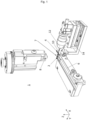
- Fig. 1 shows an embodiment of a device 1 for testing an outer conductor contact 2.
- the device 1 shown has at least one guide 6 with a feed for providing a carrier strip 4 with outer conductor contacts 2 at a fixing area 7.
- the carrier strip 4 can be provided from a storage device, such as a carrier strip roll.
- the fixing area 7 is the area on the device 1 at or in which an outer conductor contact 2 to be tested is fixed and then tested.
- the device 1 further comprises a fixing device 8 for fixing an outer conductor contact 2 to be tested to the fixing area 7.
- the fixing device 8 shown comprises at least one holding-down device.
- the fixing device 8 can comprise a support 9, onto which the outer conductor contact 2 to be tested is placed and subsequently fixed.
- the outer conductor contact 2 to be tested is clamped between the holding-down device 8 and the support 9 during fixing. Due to the clamped mounting, the outer conductor contact 2 to be tested is securely mounted and prevented from moving during the test.
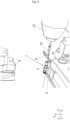
- the device 1 further comprises a test pin 10, which can be at least partially inserted into the outer conductor contact 2 (see Fig. 5 ).
- the Figs. 1 - 4 The test pin 10 shown is preferably mounted in a holder 12 and is interchangeable. Thus, depending on the outer conductor contact 2 to be tested, different test pins 10, i.e., in particular with different maximum diameters D1, can be used on the device 1.
- the holder 12 is preferably mounted on a displaceable base 14. By displacing the base 14 toward and away from the fixing area 7, the test pin 10, in particular with its test tip 11, can be moved onto or into the outer conductor contact 2 to be tested.
- the base 14 can be moved, for example, via an actuator.
- a predetermined voltage can be applied to the test pin 10, causing the test pin 10 to generate a predetermined electric field.
- the electric field is generated by a voltage at the test pin 10 in the range of 100–1000 V, more preferably in the range of 200–900 V, even more preferably in the range of 300–800 V, and most preferably in the range of 400–700 V. Due to the generated electric field, electrically conductive foreign bodies located within the outer conductor contact 2 cause a short circuit. This short circuit can be detected, thus providing information about foreign bodies in the outer conductor contact 2. If no short circuit occurs, the outer conductor contact 2 is classified as "good” and can be further processed. If a short circuit is detected, the tested outer conductor contact 2 is classified as "bad” or scrap and marked and/or further processed accordingly.
- a short circuit is primarily caused by foreign matter such as at least partially detached particles from the inner surface of the outer conductor contact.
- These at least partially detached particles can include flakes, chips, or fine hairs, which are usually still attached to one end of the inner surface of the outer conductor contact.
- the test pin 10 has a maximum diameter D1, which is present in particular at the test tip 11.
- the maximum diameter D1 of the test pin 10 is with respect to the outer conductor contact 2 is selected such that a sum of the maximum diameter D1 of the test pin 10 and twice the minimum clearance is smaller than an inner diameter D2 of the outer conductor contact 2 (see Fig. 6 ).
- maximum diameters D1 of the test pin 10 in the range of 1 - 2 mm, preferably in the range of 1.3 - 1.8 mm, are used.
- the simple minimum air gap designates a distance from the test pin 10 at which the electric field is so strong that an electrical body causes a flashover or short circuit to the test pin 10. Figuratively speaking, the simple minimum air gap surrounds the test pin 10 like an aura.
- the minimum air gap is preferably determined from a table at a predetermined degree of contamination. In practice, the minimum air distance can be determined from the standard VDE 0110-1/4.97 with a pollution degree of 1 - 4.
- Figures 2 - 4 show an embodiment of the method for testing an outer conductor contact 2.
- the method is preferably carried out before the outer conductor contact 2 is assembled onto a cable.
- the method is particularly suitable for automated testing of outer conductor contacts 2.
- the method comprises at least the following steps:
- an outer conductor contact 2 to be tested is provided at the fixing area 7 (see Fig. 2 ).
- the carrier strip 4 is moved in a feed direction X with the aid of the feed and the guide 6, so that each outer conductor contact 2 on the carrier strip 4 is arranged individually on the fixing area 7.
- the outer conductor contact 2 to be tested is placed on a Rest 9 is placed on the fixing area 7.
- the test pin 10 is held in the holder 12 and is arranged at a distance from the outer conductor contact 2.
- the outer conductor contact 2 is fixed to the fixing area 7.
- the fixing can be carried out by force and/or form closure with the aid of a fixing device 8.
- a fixing device 8 moves along a third direction Z toward the outer conductor contact 2 and clamps the outer conductor contact 2 between itself and the support 9.
- the test pin 10 is still arranged at a distance from the outer conductor contact 2.
- the test pin 10 can be moved simultaneously or with a time delay with the movement of the hold-down device 8 along a second direction Y toward the outer conductor contact 2.
- the test pin 10 is inserted at least partially into the outer conductor contact 2.
- the insertion preferably takes place via an opening 3 on the outer conductor contact 2, which is located on the future cable outgoing side, over which an inner conductor contact will later also be inserted. Later here means in a subsequent step or steps of the cable assembly.
- the test pin 10 is not live.
- the test pin 10 is nevertheless only energized when the test pin 10 has reached its end position in the outer conductor contact 2 in order to avoid unwanted short circuits due to an oblique movement.
- the end position can be freely selected.
- the test pin 10 is inserted until it stops on an insulator 5, which is arranged within the outer conductor contact 2 (see Fig. 6 ).
- the insulator 5 may already be arranged in the outer conductor contact 2 prior to the method described here.
- the test pin 10 is preferably spring-mounted in the holder 12 to prevent damage to the outer conductor contact 2 and/or the test pin 10.
- the test pin 10 After the test pin 10 is positioned in its final position in the outer conductor contact 2, a voltage is applied to the test pin 10.
- the voltage comprises a predetermined voltage value. Studies have shown that the number of false positives can be significantly reduced if a lower voltage is used, in particular significantly below 1000 V.
- the aim is to use a voltage in the range of 550 V - 650 V.
- test pin 10 While a voltage is applied to the test pin 10, a test is performed to determine whether a short circuit has occurred between the test pin 10 and at least one electrically conductive foreign body that may be located within the outer conductor contact 2.
- the test can be performed by an electrical measurement and/or an optical measurement.
- a voltage drop between the test pin 10 and the outer conductor contact 2 is detected by means of an electrical discharge.
- the test pin 10 and the outer conductor contact 2 must be connected to a measuring device via measuring contacts.
- the support 9, if made of an electrically conductive material can be connected to the measuring contact.
- a short circuit can also be detected optically, since a brief flash of light is generated during a short circuit.
- a flash of light within the outer conductor contact 2 can be detected and interpreted as a short circuit.
- the optical measuring method has the advantage over the electrical measuring method that it is used without contact.
- the outer conductor contact 2 is declared as rejected. This outer conductor contact 2 can then be marked accordingly and/or separated from the carrier strip 4 in a subsequent processing step. After the defective outer conductor contact 2 has been separated, the carrier strip 4 can then be reinserted, for example, onto a carrier strip reel. wound up, whereby the carrier strip 4 then only comprises outer conductor contacts 2 declared as "good goods".
Landscapes
- Physics & Mathematics (AREA)
- General Physics & Mathematics (AREA)
- Testing Of Short-Circuits, Discontinuities, Leakage, Or Incorrect Line Connections (AREA)
- Measuring Leads Or Probes (AREA)
Description
- Die Erfindung betrifft eine Vorrichtung sowie ein Verfahren zum Prüfen eines Außenleiterkontakts, wobei die Prüfung bevorzugt eine elektrische Prüfung umfasst und das Verfahren bevorzugt automatisiert abläuft.
- Bei der Herstellung von Außenleiterkontakten, insbesondere wie sie zur Konfektionierung von Koaxialleitungen eingesetzt werden, kann es vorkommen, dass sich auf Grund von starken Verformungen während des Stanzprozesses Material mit der Oberfläche nicht vollständig ablöst. Dieses Material bildet dann oftmals Späne oder feine Härchen, welche später einen ungewollten Kurzschluss in einem fertig konfektionierten Stecksystem verursachen können. Um solche Kurzschlüsse zu vermeiden, müssen die Späne oder Härchen gefunden und entfernt werden.
- Im Stand der Technik werden dazu elektrische Prüfverfahren an den fertig konfektionierten (Koaxial-)Leitungen durchgeführt. Insbesondere wird eine vorgegebene Spannung von zum Beispiel 500 V bei Koaxialleitungen auf den Innenleiterkontakt gelegt, um ein Überschlag, der durch elektrisch leitfähige Fremdkörper zwischen Innen- und Außenleiterkontakt hervorgerufen wird, auf den Außenleiterkontakt zu ermitteln. Da diese Prüfverfahren jedoch erst am Ende der Konfektionierung stattfinden, wird eine fehlerhafte Leitung erst dann als solche erkannt und als Ausschuss deklariert.
- Alternativ werden Außenleiterkontakte im Stand der Technik nach ihrem Fertigungsprozess bzw. Montagevorgang an eine Leitung optisch geprüft. Bei den optischen Prüfungen können Fremdbestandteile oder Kurzschlüsse allerdings je nach Lage und Erscheinung nicht zuverlässig detektiert werden.
- Relevanter Stand der Technik wird in
US 2020/072890 A1 veröffentlicht. - Es ist daher eine Aufgabe der vorliegenden Erfindung eine Vorrichtung und ein Verfahren zum effektiven Prüfen von Außenleiterkontakten bereitzustellen, um den Ausschuss zu reduzieren.
- Die oben genannte Aufgabe wird durch eine Vorrichtung nach Anspruch 1 und einem Verfahren nach Anspruch 6 gelöst. Weitere vorteilhafte Ausgestaltungsformen der Erfindung lassen sich den Unteransprüchen, der Beschreibung sowie den Zeichnungen entnehmen.
- Insbesondere wird die oben genannte Aufgabe gelöst durch eine Vorrichtung zum Prüfen eines Außenleiterkontakts aufweisend eine Führung mit einem Vorschub zum Bereitstellen eines Trägerstreifens mit Außenleiterkontakten an einem Fixierbereich, eine Fixiervorrichtung zum Fixieren eines zu prüfenden Außenleiterkontakts an dem Fixierbereich, und einen Prüfstift, der zumindest teilweise in den Außenleiterkontakt eingeführt werden kann und ein vorbestimmtes elektrisches Feld erzeugt, so dass elektrisch leitfähige Fremdkörper, die sich innerhalb des Außenleiterkontakts befinden, einen Kurzschluss verursachen.
- Mit der vorliegenden Vorrichtung ist es möglich auf einfache und zuverlässige Weise Außenleiterkontakte vor der Konfektionierung auf eine Leitung zu prüfen. Durch das Prüfen vor dem Konfektionieren kann ein defekter Außenleiterkontakt erkannt und von der weiteren Bearbeitung bzw. Konfektionierung ausgeschlossen werden. Das spart Zeit und Ressourcen, und reduziert den Ausschuss an konfektionierten Leitungen. Die Prüfung erfolgt bevorzugt im Hinblick auf Fremdkörper, die sich im Inneren des Außenleiters befinden, und die bei einem späteren Einsatz des Außenleiters in einem Steckverbinder zu einem ungewollten Kurzschluss führen. Weiterhin erkennt die vorliegende Vorrichtung Fremdkörper, wie feine metallische Haare oder Späne, die sich teilweise hinter anderen Bauteilen im Außenleiterkontakt, beispielsweise einem Isolator, verstecken und bei einem späteren Einsatz zu einem Kurzschluss führen.
- Bevorzugt wird das elektrische Feld durch eine Spannung am Prüfstift im Bereich von 100 - 1000 V, bevorzugter im Bereich von 200 - 900 V, noch bevorzugter im Bereich von 300 - 800 V, und am bevorzugtesten im Bereich von 400 - 700 V, erzeugt. Bei Spannungen über 1000 V sind besondere Sicherungsmaßnahmen erforderlich, wodurch die Vorrichtung komplizierter aufgebaut sein muss. Daher ist es wünschenswert in einem Spannungsbereich bis 1000 V zu prüfen. Darüber hinaus haben Tests gezeigt, dass je geringer die Spannung ist, die zum Prüfen verwendet wird, desto weniger Falschpositive ergeben sich.
- Bevorzugt ist ein maximaler Durchmesser des Prüfstifts in Bezug auf den Außenleiterkontakt so gewählt, dass eine Summe aus dem maximalen Durchmesser des Prüfstifts und einer doppelten Mindestluftstrecke kleiner ist als ein Innendurchmesser des Außenleiterkontakts. Befindet sich ein elektrisch leitfähiges Objekt, oder auch der Außenleiterkontakt selbst, im Bereich der Mindestluftstrecke zum Prüfstift, kommt es zum Kurzschluss. Um einen ungewollten Kurzschluss zwischen Außenleiterkontakt und Prüfstift zu vermeiden kann als eine Möglichkeit die genannte Bedingung erfüllt sein. So kann sichergestellt werden, dass lediglich Fremdkörper innerhalb des Außenleiterkontakts und nicht der Außenleiterkontakt selbst zum Kurzschluss führen.
- Bevorzugt wird die Mindestluftstrecke tabellarisch bei einem vorbestimmten Verschmutzungsgrad ermittelt. Die Mindestluftstrecken in Abhängigkeit einer angelegten Spannung am Prüfstift sind bekannt und können anhand von Tabellen einfach ermittelt werden. Sollten sich die Prüf- und/oder Einsatzbedingungen für einen Außenleiterkontakt oder Stecker ändern, kann das entsprechend anhand der Tabelleneinträge berücksichtigt werden.
- Bevorzugt wird ein Kurzschluss durch Fremdkörper wie zumindest teilweise gelöste Partikel einer Außenleiterkontaktinnenoberfläche ausgelöst. Das hat den Vorteil, dass insbesondere metallische Späne, Fäden und/oder Flitter, die bei der Herstellung der Außenleiterkontaktform auftreten, und die oft noch an der Innenoberfläche des Außenleiterkontakts haften, erkannt werden. Durch die Erkennung kann der betreffende Außenleiterkontakt als Ausschuss markiert werden, und von der weiteren Konfektionierung ausgeschlossen werden, wodurch ein späterer Kurzschluss in einer konfektionierten Leitung verhindert wird.
- Die oben genannte Aufgabe wird weiterhin insbesondere gelöst durch ein Verfahren zum Prüfen eines Außenleiterkontakts, wobei das Verfahren die folgenden Schritte aufweist: Bereitstellen eines Außenleiterkontakts an einem Fixierbereich, Fixieren des Außenleiterkontakts an dem Fixierbereich, Einführen eines Prüfstifts zumindest teilweise in den Außenleiterkontakt, wobei der Prüfstift keine Spannung aufweist, Anlegen einer Spannung an dem Prüfstift, und Prüfen, ob ein Kurzschluss zwischen dem Prüfstift und zumindest einem elektrisch leitfähigen Fremdkörper, der sich innerhalb des Außenleiterkontakts befinden kann, stattgefunden hat.
- Das vorliegende Verfahren hat den Vorteil, dass es automatisiert umgesetzt werden kann. Weiterhin ist bei dem vorliegenden Verfahren das Handling der Außenleiterkontakte an einem Trägerstreifen einfacher, als das Handling einer bereits konfektionierten Leitung. Wird ein Außenleiterkontakt als Ausschuss erkannt, kann er einfach nach dem Prüfen von dem Trägerstreifen getrennt werden und steht einer nachfolgenden Konfektionierung nicht mehr zur Verfügung. Dadurch wird das Prüfen, und insbesondere auch das nachfolgende Konfektionieren einer Leitung, viel effektiver als mit Verfahren aus dem Stand der Technik.
- Bevorzugt findet das Verfahren vor einer Konfektionierung des Außenleiterkontakts auf einer Leitung statt. Das Prüfen der Außenleiterkontakte vor der Konfektionierung auf einer Leitung hat die Vorteile, dass Ausschuss frühzeitig erkannt wird und unnötige Konfektionierungen entfallen. Dieses Vorgehen spart Zeit und Ressourcen.
- Bevorzugt wird das Einführen des Prüfstifts bis zum Anschlag an einem Isolator, der innerhalb des Außenleiterkontakts angeordnet ist, durchgeführt. Durch das Einführen des Prüfstifts bis zum Isolator wird der gesamte Bereich, der (später) für einen Kurzschluss (zwischen Innen- und Außenleiterkontakt) relevant ist, überprüft. Der Prüfstift wird jedoch auch nicht weiter als notwendig in den Außenleiterkontakt eingeführt, denn in dem Bereich des Isolators ist jeder Fremdkörper durch den Isolator verdeckt und würde nicht zu einem Kurzschluss führen. Indem erst geprüft wird, nachdem ein Isolator im Außenleiterkontakt angeordnet ist, wird Ausschuss reduziert, bei dem zwar Fremdkörper an der Innenoberfläche des Außenleiterkontakts auftreten, diese jedoch vom Isolator (vollständig) verdeckt sind. Das Prüfverfahren an sich ist unabhängig davon, ob ein Isolator bereits im Außenleiterkontakt angeordnet ist oder nicht.
- Bevorzugt wird das Prüfen durch eine elektrische Messung und/oder eine optische Messung durchgeführt. Elektrische und optische Messungen stellen voneinander unabhängige Messverfahren dar. Mit dem Einsatz beider Messverfahren zur gleichen Zeit sind redundante Messungen möglich. Durch redundante Messungen kann sich die Zuverlässigkeit der Messung erhöhen. Optische Messungen können einfacher aufgebaut sein, während elektrische Messungen genauer sein können.
- Bevorzugt erfolgt das Fixieren durch Kraft- und/oder Formschluss mit Hilfe einer Fixiervorrichtung. Der Kraft- und/oder Formschluss sind einfache Arten einen zu prüfenden Außenleiterkontakt sicher zu fixieren. Der Formschluss kann direkt auf einen bestimmten Außenleiterkontakt angepasst werden und ein Verrutschen des Außenleiterkontakts ausschließen.
- Die folgende Beschreibung von Ausführungsformen erfolgt unter Bezugnahme auf die begleitenden Figuren. Dabei zeigt:
- Fig. 1
- eine perspektivische Ansicht einer Ausführungsform einer Anlage zum Prüfen eines Außenleiterkontakts;
- Fig. 2
- eine Detailansicht von
Fig. 1 ; - Fig. 3
- die Detailansicht von
Fig. 2 mit fixiertem Außenleiter; - Fig. 4
- die Detailansicht von
Fig. 3 mit eingeführtem Prüfstift; - Fig. 5
- eine perspektivische Ansicht einer Ausführungsform eines Außenleiterkontakts mit eingeführtem Prüfstift; und
- Fig. 6
- eine Querschnittsansicht der Darstellung aus
Fig. 5 . - Im Folgenden werden bevorzugte Ausführungsformen im Detail mit Bezug auf die beigefügten Figuren beschrieben.
-
Fig. 1 zeigt eine Ausführungsform einer Vorrichtung 1 zum Prüfen eines Außenleiterkontakts 2. Die gezeigte Vorrichtung 1 weist zumindest eine Führung 6 mit einem Vorschub zum Bereitstellen eines Trägerstreifens 4 mit Außenleiterkontakten 2 an einem Fixierbereich 7 auf. Der Trägerstreifen 4 kann von einem Speicher, wie einer Trägerstreifenrolle, bereitgestellt werden. Der Fixierbereich 7 ist der Bereich an der Vorrichtung 1, an oder in dem ein zu prüfender Außenleiterkontakt 2 fixiert und dann geprüft wird. - Die Vorrichtung 1 weist weiterhin eine Fixiervorrichtung 8 zum Fixieren eines zu prüfenden Außenleiterkontakts 2 an dem Fixierbereich 7 auf. Die in den
Figuren 1 -4 dargestellte Fixiervorrichtung 8 umfasst zumindest einen Niederhalter. Weiterhin kann die Fixiervorrichtung 8 eine Auflage 9 umfassen, auf die der zu prüfende Außenleiterkontakt 2 abgelegt und später fixiert wird. Bevorzugt wird der zu prüfende Außenleiterkontakt 2 beim Fixieren zwischen dem Niederhalter 8 und der Auflage 9 geklemmt. Durch die geklemmte Lagerung ist der zu prüfende Außenleiterkontakt 2 während der Prüfung sicher und bewegungsgehindert gelagert. - Die Vorrichtung 1 umfasst weiterhin einen Prüfstift 10, der zumindest teilweise in den Außenleiterkontakt 2 eingeführt werden kann (s.
Fig. 5 ). Der inFigs. 1 - 4 dargestellte Prüfstift 10 ist bevorzugt in einer Halterung 12 gelagert und austauschbar. So können je nach zu prüfendem Außenleiterkontakt 2 verschiedene Prüfstifte 10, d.h. insbesondere mit verschiedenen maximalen Durchmessern D1, an der Vorrichtung 1 verwendet werden. Die Halterung 12 ist bevorzugt auf einer verschiebbaren Basis 14 gelagert. Über ein Verschieben der Basis 14 hin und weg von dem Fixierbereich 7 kann der Prüfstift 10, insbesondere mit seiner Prüfspitze 11, an oder in den zu prüfenden Außenleiterkontakt 2 bewegt werden. Die Basis 14 kann zum Beispiel über einen Aktuator bewegt werden. - An den Prüfstift 10 kann eine vorbestimmte Spannung angelegt werden, so dass der Prüfstift 10 ein vorbestimmtes elektrisches Feld erzeugt. Das elektrische Feld wird durch eine Spannung am Prüfstift 10 im Bereich von 100 - 1000 V, bevorzugter im Bereich von 200 - 900 V, noch bevorzugter im Bereich von 300 - 800 V, und am bevorzugtesten im Bereich von 400 - 700 V, erzeugt. Durch das erzeugte elektrische Feld verursachen elektrisch leitfähige Fremdkörper, die sich innerhalb des Außenleiterkontakts 2 befinden, einen Kurzschluss. Diesen Kurzschluss kann man detektieren und erhält somit Rückschluss auf Fremdkörper im Außenleiterkontakt 2. Findet kein Kurzschluss statt, wird der Außenleiterkontakt 2 als "Gutware" klassifiziert und kann weiterverarbeitet werden. Wird ein Kurzschluss detektiert wird der geprüfte Außenleiterkontakt 2 als "Schlechtware" oder Ausschuss klassifiziert und entsprechend markiert und/oder weiterbehandelt. Ein Kurzschluss wird in der Praxis hauptsächlich durch Fremdkörper wie zumindest teilweise gelöste Partikel einer Außenleiterkontaktinnenoberfläche ausgelöst. Die zumindest teilweise gelösten Partikel können Flitter, Späne oder feine Härchen umfassen, die in der Regel noch mit einem Ende an der Innenoberfläche des Außenleiterkontakts verbunden sind.
- Der Prüfstift 10 weist einen maximalen Durchmesser D1 auf, der insbesondere an der Prüfspitze 11 vorliegt. Der maximale Durchmesser D1 des Prüfstifts 10 ist dabei in Bezug auf den Außenleiterkontakt 2 so gewählt, dass eine Summe aus dem maximalen Durchmesser D1 des Prüfstifts 10 und einer doppelten Mindestluftstrecke kleiner ist als ein Innendurchmesser D2 des Außenleiterkontakts 2 (s.
Fig. 6 ). In der Praxis werden maximale Durchmesser D1 des Prüfstifts 10 im Bereich von 1 - 2 mm, bevorzugt im Bereich von 1,3 - 1,8 mm, verwendet. Die einfache Mindestluftstrecke benennt einen Abstand zum Prüfstift 10, in dem das elektrische Feld so stark wirkt, dass ein elektrischer Körper einen Überschlag oder Kurzschluss zum Prüfstift 10 verursacht. Bildlich gesprochen umgibt die einfache Mindestluftstrecke den Prüfstift 10 wie eine Aura. Im Durchmesser betrachtet man die doppelte Mindestluftstrecke, d.h. jeweils eine einfache Mindestluftstrecke auf beiden Seiten des Prüfstifts 10. Innerhalb dieser Aura, die wie ein vergrößerter Außenumfang des Prüfstift 10 wirkt, wirkt das elektrische Feld des Prüfstifts so stark, dass alle elektrisch leitfähigen Körper, die sich innerhalb der Aura oder Mindestluftstrecke befinden, einen Überschlag oder Kurzschluss erzeugen. Die Mindestluftstrecke wird bevorzugt tabellarisch bei einem vorbestimmten Verschmutzungsgrad ermittelt. In der Praxis kann die Mindestluftstrecke aus der Norm VDE 0110-1/4.97 mit einem Verschmutzungsgrad 1 - 4 tabellarisch ermittelt werden. -
Figuren 2 - 4 zeigen eine Ausführungsform des Verfahrens zum Prüfen eines Außenleiterkontakts 2. Das Verfahren wird bevorzugt vor einer Konfektionierung des Außenleiterkontakts 2 auf eine Leitung durchgeführt. Das Verfahren ist insbesondere für eine automatisierte Prüfung von Außenleiterkontakten 2 geeignet. Das Verfahren weist zumindest die folgenden Schritte auf: - In einem ersten Schritt erfolgt ein Bereitstellen eines zu prüfenden Außenleiterkontakts 2 an dem Fixierbereich 7 (s.
Fig. 2 ). Zum Bereitstellen wird der Trägerstreifen 4 mit Hilfe des Vorschubs und der Führung 6 in einer Vorschubrichtung X bewegt, so dass nacheinander jeder Außenleiterkontakt 2 an dem Trägerstreifen 4 einzeln an dem Fixierbereich 7 angeordnet wird. In der dargestellten Ausführungsform wird der zu prüfende Außenleiterkontakt 2 auf einer Auflage 9 am Fixierbereich 7 abgelegt. Der Prüfstift 10 wird in der Halterung 12 gehalten und ist vom Außenleiterkontakt 2 beabstandet angeordnet. - Nach dem Bereitstellen erfolgt ein Fixieren des Außenleiterkontakts 2 an dem Fixierbereich 7. Das Fixieren kann durch Kraft- und/oder Formschluss mit Hilfe einer Fixiervorrichtung 8 erfolgen. Eine Ausführungsform des Fixierens ist in
Fig. 3 gezeigt. In dieser Ausführungsform bewegt sich zum Fixieren ein Niederhalter 8 entlang einer dritten Richtung Z zum Außenleiterkontakt 2 und klemmt den Außenleiterkontakt 2 zwischen sich und der Auflage 9 ein. Der Prüfstift 10 ist dabei immer noch beabstandet zum Außenleiterkontakt 2 angeordnet. In einer alternativen Ausführungsform kann der Prüfstift 10 zeitgleich oder zeitversetzt mit der Bewegung des Niederhalters 8 entlang einer zweiten Richtung Y zum Außenleiterkontakt 2 bewegt werden. - Nachdem der zu prüfende Außenleiterkontakt 2 fixiert ist, erfolgt ein Einführen des Prüfstifts 10 zumindest teilweise in den Außenleiterkontakt 2. Das Einführen erfolgt bevorzugt über eine Öffnung 3 am Außenleiterkontakt 2, die sich auf der späteren Kabelabgangsseite befindet, über welche später auch ein Innenleiterkontakt gefügt wird. Später meint dabei in einem nachfolgenden Schritt oder Schritten der Kabelkonfektion. Während des Einführens weist der Prüfstift 10 keine Spannung auf. Obwohl der Außenleiterkontakt 2 mit seiner Mittelachse M in der Praxis so ausgerichtet ist, dass sich der Prüfstift 10 entlang dieser Mittelachse M in oder aus dem Außenleiterkontakt 2 bewegt, wird der Prüfstift 10 dennoch erst unter Spannung gesetzt, wenn der Prüfstift 10 seine Endposition im Außenleiterkontakt 2 erreicht hat, um ungewollte Kurzschlüsse aufgrund einer schiefen Bewegung zu vermeiden. Die Endposition ist frei wählbar. Bevorzugt erfolgt das Einführen des Prüfstifts 10 bis zum Anschlag an einem Isolator 5, der innerhalb des Außenleiterkontakts 2 angeordnet ist (s.
Fig. 6 ). Der Isolator 5 kann vor dem hier beschriebenen Verfahren bereits in dem Außenleiterkontakt 2 angeordnet sein. Der Prüfstift 10 ist bevorzugt federnd in der Halterung 12 gelagert, damit es zu keiner Beschädigung am Außenleiterkontakt 2 und/oder Prüfstift 10 kommt. - Nachdem der Prüfstift 10 in seiner Endposition im Außenleiterkontakt 2 angeordnet ist, erfolgt ein Anlegen einer Spannung an dem Prüfstift 10. Die Spannung umfasst einen vorbestimmten Spannungswert. In Untersuchungen hat sich ergeben, dass die Anzahl an Falschpositiven deutlich gesenkt werden kann, wenn eine geringere Spannung, insbesondere deutlich unter 1000 V, verwendet wird. Angestrebt wird eine Spannung im Bereich von 550 V - 650 V zu verwenden.
- Während eine Spannung an dem Prüfstift 10 angelegt wird, erfolgt ein Prüfen, ob ein Kurzschluss zwischen dem Prüfstift 10 und zumindest einem elektrisch leitfähigen Fremdkörper, der sich innerhalb des Außenleiterkontakts 2 befinden kann, stattgefunden hat. Das Prüfen kann dabei durch eine elektrische Messung und/oder eine optische Messung durchgeführt werden. Bei einer elektrischen Messung wird ein Spannungsabfall zwischen dem Prüfstift 10 und dem Außenleiterkontakt 2 anhand einer elektrischen Ableitung detektiert. Für das elektrische Messverfahren müssen Prüfstift 10 und Außenleiterkontakt 2 über Messkontakte mit einer Messvorrichtung verbunden sein. Optional kann anstatt den Außenleiterkontakt 2 mit einem Messkontakt zu verbinden, die Auflage 9, wenn sie aus einem elektrisch leitfähigen Material gebildet ist, mit dem Messkontakt verbunden werden. Unabhängig von dem elektrischen Messverfahren kann ein Kurzschluss auch optisch detektiert werden, da sich beim Kurzschluss ein kurzer Lichtblitz bildet. Mit einer/einem optischen Messvorrichtung/Messverfahren kann ein Lichtblitz innerhalb des Außenleiterkontakts 2 erkannt werden und auf einen Kurzschluss zurückgedeutet werden. Das optische Messverfahren hat gegenüber dem elektrischen Messverfahren den Vorteil, dass es kontaktierungsfrei verwendet wird.
- Tritt während des Prüfens ein Kurzschluss auf, so wird der Außenleiterkontakt 2 als Ausschuss deklariert. Dieser Außenleiterkontakt 2 kann dann entsprechend markiert werden und/oder in einem nachfolgenden Bearbeitungsschritt vom Trägerstreifen 4 getrennt werden. Nach der Abtrennung des fehlerhaften Außenleiterkontakts 2 kann der Trägerstreifen 4 abschließend zum Beispiel wieder auf eine Trägerstreifenrolle aufgewickelt werden, wobei der Trägerstreifen 4 dann nur noch als "Gutware" deklarierte Außenleiterkontakte 2 umfasst.
-
- 1
- Vorrichtung
- 2
- Außenleiterkontakt
- 3
- Öffnung
- 4
- Trägerstreifen
- 5
- Isolator
- 6
- Führung
- 7
- Fixierbereich
- 8
- Fixiervorrichtung
- 9
- Auflage
- 10
- Prüfstift
- 11
- Prüfspitze
- 12
- Halterung
- 14
- Basis
- D1
- maximaler Durchmesser
- D2
- Innendurchmesser
- M
- Mittelachse
- X
- Vorschubrichtung
- Y
- zweite Richtung
- Z
- dritte Richtung
Claims (10)
- Vorrichtung (1) zum Prüfen eines Außenleiterkontakts (2) aufweisend:a) eine Führung (6) mit einem Vorschub zum Bereitstellen eines Trägerstreifens (4) mit Außenleiterkontakten (2) an einem Fixierbereich (7);b) eine Fixiervorrichtung (8) zum Fixieren eines zu prüfenden Außenleiterkontakts (2) an dem Fixierbereich (7);
gekennzeichnet durchc) einen Prüfstift (10), der zumindest teilweise in den Außenleiterkontakt (2) eingeführt werden kann und ausgebildet ist, ein vorbestimmtes elektrisches Feld zu erzeugen, so dass elektrisch leitfähige Fremdkörper, die sich innerhalb des Außenleiterkontakts (2) befinden, einen Kurzschluss verursachen. - Vorrichtung (1) nach Anspruch 1, bei dem das elektrische Feld durch eine Spannung am Prüfstift (10) im Bereich von 100 - 1000 V, bevorzugter im Bereich von 200 - 900 V, noch bevorzugter im Bereich von 300 - 800 V, und am bevorzugtesten im Bereich von 400 - 700 V, erzeugt wird.
- Vorrichtung (1) nach Anspruch 1 oder 2, bei dem ein maximaler Durchmesser (D1) des Prüfstifts (10) in Bezug auf den Außenleiterkontakt (2) so gewählt ist, dass eine Summe aus dem maximalen Durchmesser (D1) des Prüfstifts (10) und einer doppelten Mindestluftstrecke kleiner ist als ein Innendurchmesser (D2) des Außenleiterkontakts (2).
- Vorrichtung (1) nach Anspruch 3, bei dem die Mindestluftstrecke tabellarisch bei einem vorbestimmten Verschmutzungsgrad ermittelt wird.
- Vorrichtung (1) nach einem der Ansprüche 1 - 4, bei dem ein Kurzschluss durch Fremdkörper wie zumindest teilweise gelöste Partikel einer Außenleiterkontaktinnenoberfläche ausgelöst wird.
- Verfahren zum Prüfen eines Außenleiterkontakts (2), wobei das Verfahren die folgenden Schritte aufweist:a) Bereitstellen eines Außenleiterkontakts (2) an einem Fixierbereich (7);b) Fixieren des Außenleiterkontakts (2) an dem Fixierbereich (7);c) Einführen eines Prüfstifts (10) zumindest teilweise in den Außenleiterkontakt (2), wobei der Prüfstift (10) keine Spannung aufweist;d) Anlegen einer Spannung an dem Prüfstift (10); unde) Prüfen, ob ein Kurzschluss zwischen dem Prüfstift (10) und zumindest einem elektrisch leitfähigen Fremdkörper, der sich innerhalb des Außenleiterkontakts (2) befinden kann, stattgefunden hat.
- Verfahren nach Anspruch 6, bei dem das Verfahren vor einer Konfektionierung des Außenleiterkontakts (2) auf einer Leitung stattfindet.
- Verfahren nach Anspruch 6 oder 7, bei dem das Einführen des Prüfstifts (10) bis zum Anschlag an einem Isolator (5), der innerhalb des Außenleiterkontakts (2) angeordnet ist, durchgeführt wird.
- Verfahren nach einem der Ansprüche 6 - 8, bei dem das Prüfen durch eine elektrische Messung und/oder eine optische Messung durchgeführt wird.
- Verfahren nach einem der Ansprüche 6 - 9, bei dem das Fixieren durch Kraft- und/oder Formschluss mit Hilfe einer Fixiervorrichtung (8) erfolgt.
Applications Claiming Priority (1)
| Application Number | Priority Date | Filing Date | Title |
|---|---|---|---|
| DE102023106422.3A DE102023106422A1 (de) | 2023-03-15 | 2023-03-15 | Vorrichtung und Verfahren zum Prüfen eines Außenleiterkontakts |
Publications (2)
| Publication Number | Publication Date |
|---|---|
| EP4431957A1 EP4431957A1 (de) | 2024-09-18 |
| EP4431957B1 true EP4431957B1 (de) | 2025-06-04 |
Family
ID=89164320
Family Applications (1)
| Application Number | Title | Priority Date | Filing Date |
|---|---|---|---|
| EP23215193.6A Active EP4431957B1 (de) | 2023-03-15 | 2023-12-08 | Vorrichtung und verfahren zum prüfen eines aussenleiterkontakts |
Country Status (4)
| Country | Link |
|---|---|
| EP (1) | EP4431957B1 (de) |
| CN (1) | CN118671645A (de) |
| DE (1) | DE102023106422A1 (de) |
| MX (1) | MX2024002114A (de) |
Family Cites Families (5)
| Publication number | Priority date | Publication date | Assignee | Title |
|---|---|---|---|---|
| DE202004019162U1 (de) * | 2004-12-07 | 2005-03-03 | Md Elektronik Gmbh Kabelkonfektion & Kunststofftechnik | Prüfgerät für einen elektrischen Kraftfahrzeugstecker |
| CN110031693A (zh) * | 2018-01-12 | 2019-07-19 | 康普技术有限责任公司 | 用于测试同轴连接器的无源互调的测试工装和方法 |
| JP6892422B2 (ja) * | 2018-09-04 | 2021-06-23 | 矢崎総業株式会社 | 同軸ケーブルの端子状態測定装置 |
| CN110376496A (zh) * | 2019-08-12 | 2019-10-25 | 嘉兴翼波电子有限公司 | 用于射频同轴电缆组件耐压测试的端口转接及测试装置 |
| DE102022107798A1 (de) * | 2022-04-01 | 2023-10-05 | Md Elektronik Gmbh | Werkzeug, Anlage und Verfahren zur Kabelkonfektion |
-
2023
- 2023-03-15 DE DE102023106422.3A patent/DE102023106422A1/de active Pending
- 2023-12-08 EP EP23215193.6A patent/EP4431957B1/de active Active
-
2024
- 2024-02-01 CN CN202410148277.2A patent/CN118671645A/zh active Pending
- 2024-02-15 MX MX2024002114A patent/MX2024002114A/es unknown
Also Published As
| Publication number | Publication date |
|---|---|
| CN118671645A (zh) | 2024-09-20 |
| DE102023106422A1 (de) | 2024-09-19 |
| EP4431957A1 (de) | 2024-09-18 |
| MX2024002114A (es) | 2024-09-16 |
Similar Documents
| Publication | Publication Date | Title |
|---|---|---|
| DE3408704C2 (de) | Verfahren zum Prüfen von starren oder flexiblen elektrischen Verbindungsnetzwerk-Schaltungen und Vorrichtung zur Durchführung des Verfahrens | |
| EP2083260B1 (de) | Vorrichtung und Verfahren zur Untersuchung der Oberfläche eines Bauteils | |
| DE2360801A1 (de) | Pruefeinrichtung mit kontaktiereinrichtung | |
| EP4231006A1 (de) | Vorrichtung und verfahren zum prüfen einer innenwandfläche eines rohrs | |
| DE102023203537A1 (de) | Verfahren sowie Anlage zur Überprüfung der Spannungsfestigkeit einer Isolierung eines elektrischen Kabelsatzes | |
| DE69110176T2 (de) | Fehlerfeststellung und -isolierung in einem Automobilkabelbaum. | |
| DE10039928A1 (de) | Vorrichtung zum automatisierten Testen, Kalibrieren und Charakterisieren von Testadaptern | |
| DE2653590C3 (de) | Vorrichtung zum Ermitteln von Fehlern in flächenhaften Mustern, insbesondere in Photomasken | |
| DE102018105507B4 (de) | Vorrichtung zum Prüfen einer Kontaktkraft einer elektromechanischen Verbindung und Ladevorrichtung für ein Elektrofahrzeug | |
| DE19525229A1 (de) | Verfahren und Vorrichtung zum Prüfen eines Kabelbaums | |
| EP4431957A1 (de) | Vorrichtung und verfahren zum prüfen eines aussenleiterkontakts | |
| WO2020200828A1 (de) | Vorrichtung, verfahren und system zur konfektionierung eines elektrischen kabels | |
| DE19739923C2 (de) | Verfahren und Vorrichtung zur gepulsten Hochstrombelastung integrierter Schaltungen und Strukturen | |
| DE10131665B4 (de) | Verfahren und Vorrichtung zur Inspektion des Randbereichs eines Halbleiterwafers | |
| WO2020070187A1 (de) | Prüfvorrichtung und verfahren zum prüfen eines übergangswiderstandes an mindestens einem stiftkontakt eines steckverbinders | |
| DE19654231A1 (de) | Bauelement-Handler mit Dreharm und Bauelement-Halter | |
| DE102019108831B3 (de) | Kontaktstift und prüfadapter zum überprüfen eines elektrischen steckverbinders | |
| EP0427661A2 (de) | Werkzeugidentifikation | |
| EP1920263B1 (de) | VERFAHREN ZUM TESTEN VON UNBESTÜCKTEN, GROßFLÄCHIGEN LEITERPLATTEN MIT EINEM FINGERTESTER | |
| EP1912296A1 (de) | Einrichtung und Verfahren zur Bestimmung der Lage einer Kabelbestückung an einem Kabel | |
| DE68915781T2 (de) | Elektrische testsonde. | |
| EP4141377B1 (de) | Anlage und prüfverfahren für die kabelkonfektion | |
| EP3014291B1 (de) | Teilleiterschlussprüfung von ständerstäben elektrischer maschinen | |
| DE69934604T2 (de) | Vorrichtung zur prüfung von kondomen | |
| DE102018208073B3 (de) | Verfahren zum Testen eines Audiokommunikationssystems eines Luftfahrzeugs sowie Luftfahrzeug mit einem Audiokommunikationssystem |
Legal Events
| Date | Code | Title | Description |
|---|---|---|---|
| PUAI | Public reference made under article 153(3) epc to a published international application that has entered the european phase |
Free format text: ORIGINAL CODE: 0009012 |
|
| STAA | Information on the status of an ep patent application or granted ep patent |
Free format text: STATUS: THE APPLICATION HAS BEEN PUBLISHED |
|
| AK | Designated contracting states |
Kind code of ref document: A1 Designated state(s): AL AT BE BG CH CY CZ DE DK EE ES FI FR GB GR HR HU IE IS IT LI LT LU LV MC ME MK MT NL NO PL PT RO RS SE SI SK SM TR |
|
| STAA | Information on the status of an ep patent application or granted ep patent |
Free format text: STATUS: REQUEST FOR EXAMINATION WAS MADE |
|
| 17P | Request for examination filed |
Effective date: 20240925 |
|
| RBV | Designated contracting states (corrected) |
Designated state(s): AL AT BE BG CH CY CZ DE DK EE ES FI FR GB GR HR HU IE IS IT LI LT LU LV MC ME MK MT NL NO PL PT RO RS SE SI SK SM TR |
|
| GRAP | Despatch of communication of intention to grant a patent |
Free format text: ORIGINAL CODE: EPIDOSNIGR1 |
|
| STAA | Information on the status of an ep patent application or granted ep patent |
Free format text: STATUS: GRANT OF PATENT IS INTENDED |
|
| INTG | Intention to grant announced |
Effective date: 20250124 |
|
| GRAS | Grant fee paid |
Free format text: ORIGINAL CODE: EPIDOSNIGR3 |
|
| GRAA | (expected) grant |
Free format text: ORIGINAL CODE: 0009210 |
|
| STAA | Information on the status of an ep patent application or granted ep patent |
Free format text: STATUS: THE PATENT HAS BEEN GRANTED |
|
| AK | Designated contracting states |
Kind code of ref document: B1 Designated state(s): AL AT BE BG CH CY CZ DE DK EE ES FI FR GB GR HR HU IE IS IT LI LT LU LV MC ME MK MT NL NO PL PT RO RS SE SI SK SM TR |
|
| REG | Reference to a national code |
Ref country code: GB Ref legal event code: FG4D Free format text: NOT ENGLISH |
|
| REG | Reference to a national code |
Ref country code: CH Ref legal event code: EP |
|
| REG | Reference to a national code |
Ref country code: DE Ref legal event code: R096 Ref document number: 502023001096 Country of ref document: DE |
|
| REG | Reference to a national code |
Ref country code: IE Ref legal event code: FG4D Free format text: LANGUAGE OF EP DOCUMENT: GERMAN |
|
| REG | Reference to a national code |
Ref country code: NL Ref legal event code: MP Effective date: 20250604 |
|
| PG25 | Lapsed in a contracting state [announced via postgrant information from national office to epo] |
Ref country code: ES Free format text: LAPSE BECAUSE OF FAILURE TO SUBMIT A TRANSLATION OF THE DESCRIPTION OR TO PAY THE FEE WITHIN THE PRESCRIBED TIME-LIMIT Effective date: 20250604 Ref country code: FI Free format text: LAPSE BECAUSE OF FAILURE TO SUBMIT A TRANSLATION OF THE DESCRIPTION OR TO PAY THE FEE WITHIN THE PRESCRIBED TIME-LIMIT Effective date: 20250604 |
|
| REG | Reference to a national code |
Ref country code: LT Ref legal event code: MG9D |
|
| PG25 | Lapsed in a contracting state [announced via postgrant information from national office to epo] |
Ref country code: NO Free format text: LAPSE BECAUSE OF FAILURE TO SUBMIT A TRANSLATION OF THE DESCRIPTION OR TO PAY THE FEE WITHIN THE PRESCRIBED TIME-LIMIT Effective date: 20250904 Ref country code: GR Free format text: LAPSE BECAUSE OF FAILURE TO SUBMIT A TRANSLATION OF THE DESCRIPTION OR TO PAY THE FEE WITHIN THE PRESCRIBED TIME-LIMIT Effective date: 20250905 |
|
| PG25 | Lapsed in a contracting state [announced via postgrant information from national office to epo] |
Ref country code: PL Free format text: LAPSE BECAUSE OF FAILURE TO SUBMIT A TRANSLATION OF THE DESCRIPTION OR TO PAY THE FEE WITHIN THE PRESCRIBED TIME-LIMIT Effective date: 20250604 |
|
| PG25 | Lapsed in a contracting state [announced via postgrant information from national office to epo] |
Ref country code: HR Free format text: LAPSE BECAUSE OF FAILURE TO SUBMIT A TRANSLATION OF THE DESCRIPTION OR TO PAY THE FEE WITHIN THE PRESCRIBED TIME-LIMIT Effective date: 20250604 |
|
| PG25 | Lapsed in a contracting state [announced via postgrant information from national office to epo] |
Ref country code: RS Free format text: LAPSE BECAUSE OF FAILURE TO SUBMIT A TRANSLATION OF THE DESCRIPTION OR TO PAY THE FEE WITHIN THE PRESCRIBED TIME-LIMIT Effective date: 20250904 |
|
| PG25 | Lapsed in a contracting state [announced via postgrant information from national office to epo] |
Ref country code: LV Free format text: LAPSE BECAUSE OF FAILURE TO SUBMIT A TRANSLATION OF THE DESCRIPTION OR TO PAY THE FEE WITHIN THE PRESCRIBED TIME-LIMIT Effective date: 20250604 |
|
| PG25 | Lapsed in a contracting state [announced via postgrant information from national office to epo] |
Ref country code: NL Free format text: LAPSE BECAUSE OF FAILURE TO SUBMIT A TRANSLATION OF THE DESCRIPTION OR TO PAY THE FEE WITHIN THE PRESCRIBED TIME-LIMIT Effective date: 20250604 |
|
| PG25 | Lapsed in a contracting state [announced via postgrant information from national office to epo] |
Ref country code: PT Free format text: LAPSE BECAUSE OF FAILURE TO SUBMIT A TRANSLATION OF THE DESCRIPTION OR TO PAY THE FEE WITHIN THE PRESCRIBED TIME-LIMIT Effective date: 20251006 |
|
| PG25 | Lapsed in a contracting state [announced via postgrant information from national office to epo] |
Ref country code: IS Free format text: LAPSE BECAUSE OF FAILURE TO SUBMIT A TRANSLATION OF THE DESCRIPTION OR TO PAY THE FEE WITHIN THE PRESCRIBED TIME-LIMIT Effective date: 20251004 |
|
| PGFP | Annual fee paid to national office [announced via postgrant information from national office to epo] |
Ref country code: DE Payment date: 20251211 Year of fee payment: 3 |
|
| PG25 | Lapsed in a contracting state [announced via postgrant information from national office to epo] |
Ref country code: SM Free format text: LAPSE BECAUSE OF FAILURE TO SUBMIT A TRANSLATION OF THE DESCRIPTION OR TO PAY THE FEE WITHIN THE PRESCRIBED TIME-LIMIT Effective date: 20250604 |
|
| PGFP | Annual fee paid to national office [announced via postgrant information from national office to epo] |
Ref country code: AT Payment date: 20260113 Year of fee payment: 3 |
|
| PGFP | Annual fee paid to national office [announced via postgrant information from national office to epo] |
Ref country code: CZ Payment date: 20251202 Year of fee payment: 3 |
|
| PGFP | Annual fee paid to national office [announced via postgrant information from national office to epo] |
Ref country code: BG Payment date: 20251219 Year of fee payment: 3 |
|
| PG25 | Lapsed in a contracting state [announced via postgrant information from national office to epo] |
Ref country code: EE Free format text: LAPSE BECAUSE OF FAILURE TO SUBMIT A TRANSLATION OF THE DESCRIPTION OR TO PAY THE FEE WITHIN THE PRESCRIBED TIME-LIMIT Effective date: 20250604 |
|
| PG25 | Lapsed in a contracting state [announced via postgrant information from national office to epo] |
Ref country code: SK Free format text: LAPSE BECAUSE OF FAILURE TO SUBMIT A TRANSLATION OF THE DESCRIPTION OR TO PAY THE FEE WITHIN THE PRESCRIBED TIME-LIMIT Effective date: 20250604 |
|
| PG25 | Lapsed in a contracting state [announced via postgrant information from national office to epo] |
Ref country code: IT Free format text: LAPSE BECAUSE OF FAILURE TO SUBMIT A TRANSLATION OF THE DESCRIPTION OR TO PAY THE FEE WITHIN THE PRESCRIBED TIME-LIMIT Effective date: 20250604 |
|
| REG | Reference to a national code |
Ref country code: DE Ref legal event code: R097 Ref document number: 502023001096 Country of ref document: DE |
|
| PG25 | Lapsed in a contracting state [announced via postgrant information from national office to epo] |
Ref country code: RO Free format text: LAPSE BECAUSE OF FAILURE TO SUBMIT A TRANSLATION OF THE DESCRIPTION OR TO PAY THE FEE WITHIN THE PRESCRIBED TIME-LIMIT Effective date: 20250604 |
|
| PLBE | No opposition filed within time limit |
Free format text: ORIGINAL CODE: 0009261 |
|
| STAA | Information on the status of an ep patent application or granted ep patent |
Free format text: STATUS: NO OPPOSITION FILED WITHIN TIME LIMIT |
|
| PG25 | Lapsed in a contracting state [announced via postgrant information from national office to epo] |
Ref country code: DK Free format text: LAPSE BECAUSE OF FAILURE TO SUBMIT A TRANSLATION OF THE DESCRIPTION OR TO PAY THE FEE WITHIN THE PRESCRIBED TIME-LIMIT Effective date: 20250604 |
|
| REG | Reference to a national code |
Ref country code: CH Ref legal event code: L10 Free format text: ST27 STATUS EVENT CODE: U-0-0-L10-L00 (AS PROVIDED BY THE NATIONAL OFFICE) Effective date: 20260416 |
|
| 26N | No opposition filed |
Effective date: 20260305 |