EP4431684A1 - Gleitschienenmechanismus und einstellvorrichtung dafür - Google Patents
Gleitschienenmechanismus und einstellvorrichtung dafür Download PDFInfo
- Publication number
- EP4431684A1 EP4431684A1 EP23184168.5A EP23184168A EP4431684A1 EP 4431684 A1 EP4431684 A1 EP 4431684A1 EP 23184168 A EP23184168 A EP 23184168A EP 4431684 A1 EP4431684 A1 EP 4431684A1
- Authority
- EP
- European Patent Office
- Prior art keywords
- rail
- adjustment device
- driving member
- slide rail
- auxiliary device
- Prior art date
- Legal status (The legal status is an assumption and is not a legal conclusion. Google has not performed a legal analysis and makes no representation as to the accuracy of the status listed.)
- Granted
Links
Images




Classifications
-
- E—FIXED CONSTRUCTIONS
- E05—LOCKS; KEYS; WINDOW OR DOOR FITTINGS; SAFES
- E05B—LOCKS; ACCESSORIES THEREFOR; HANDCUFFS
- E05B65/00—Locks or fastenings for special use
- E05B65/46—Locks or fastenings for special use for drawers
- E05B65/462—Locks or fastenings for special use for drawers for two or more drawers
- E05B65/463—Drawer interlock or anti-tilt mechanisms, i.e. when one drawer is open, at least one of the remaining drawers is locked
- E05B65/464—Drawer interlock or anti-tilt mechanisms, i.e. when one drawer is open, at least one of the remaining drawers is locked comprising two or more lock elements aligned in end-to-end abutting relation
-
- E—FIXED CONSTRUCTIONS
- E05—LOCKS; KEYS; WINDOW OR DOOR FITTINGS; SAFES
- E05B—LOCKS; ACCESSORIES THEREFOR; HANDCUFFS
- E05B65/00—Locks or fastenings for special use
- E05B65/46—Locks or fastenings for special use for drawers
- E05B65/462—Locks or fastenings for special use for drawers for two or more drawers
- E05B65/463—Drawer interlock or anti-tilt mechanisms, i.e. when one drawer is open, at least one of the remaining drawers is locked
- E05B65/465—Drawer interlock or anti-tilt mechanisms, i.e. when one drawer is open, at least one of the remaining drawers is locked with rotary locking bars
-
- A—HUMAN NECESSITIES
- A47—FURNITURE; DOMESTIC ARTICLES OR APPLIANCES; COFFEE MILLS; SPICE MILLS; SUCTION CLEANERS IN GENERAL
- A47B—TABLES; DESKS; OFFICE FURNITURE; CABINETS; DRAWERS; GENERAL DETAILS OF FURNITURE
- A47B88/00—Drawers for tables, cabinets or like furniture; Guides for drawers
- A47B88/40—Sliding drawers; Slides or guides therefor
- A47B88/44—Sequencing or synchronisation of drawer slides or functional units
- A47B88/447—Simultaneous movement of rails within drawer slides, i.e. with a coordination of movement with all rail elements moving at the same time
-
- A—HUMAN NECESSITIES
- A47—FURNITURE; DOMESTIC ARTICLES OR APPLIANCES; COFFEE MILLS; SPICE MILLS; SUCTION CLEANERS IN GENERAL
- A47B—TABLES; DESKS; OFFICE FURNITURE; CABINETS; DRAWERS; GENERAL DETAILS OF FURNITURE
- A47B88/00—Drawers for tables, cabinets or like furniture; Guides for drawers
- A47B88/40—Sliding drawers; Slides or guides therefor
- A47B88/49—Sliding drawers; Slides or guides therefor with double extensible guides or parts
-
- A—HUMAN NECESSITIES
- A47—FURNITURE; DOMESTIC ARTICLES OR APPLIANCES; COFFEE MILLS; SPICE MILLS; SUCTION CLEANERS IN GENERAL
- A47B—TABLES; DESKS; OFFICE FURNITURE; CABINETS; DRAWERS; GENERAL DETAILS OF FURNITURE
- A47B97/00—Furniture or accessories for furniture, not provided for in other groups of this subclass
-
- E—FIXED CONSTRUCTIONS
- E05—LOCKS; KEYS; WINDOW OR DOOR FITTINGS; SAFES
- E05B—LOCKS; ACCESSORIES THEREFOR; HANDCUFFS
- E05B63/00—Locks or fastenings with special structural characteristics
- E05B63/0056—Locks with adjustable or exchangeable lock parts
-
- A—HUMAN NECESSITIES
- A47—FURNITURE; DOMESTIC ARTICLES OR APPLIANCES; COFFEE MILLS; SPICE MILLS; SUCTION CLEANERS IN GENERAL
- A47B—TABLES; DESKS; OFFICE FURNITURE; CABINETS; DRAWERS; GENERAL DETAILS OF FURNITURE
- A47B97/00—Furniture or accessories for furniture, not provided for in other groups of this subclass
- A47B2097/008—Anti-tip devices
-
- A—HUMAN NECESSITIES
- A47—FURNITURE; DOMESTIC ARTICLES OR APPLIANCES; COFFEE MILLS; SPICE MILLS; SUCTION CLEANERS IN GENERAL
- A47B—TABLES; DESKS; OFFICE FURNITURE; CABINETS; DRAWERS; GENERAL DETAILS OF FURNITURE
- A47B2210/00—General construction of drawers, guides and guide devices
- A47B2210/0002—Guide construction for drawers
- A47B2210/0064—Guide sequencing or synchronisation
- A47B2210/007—Three slide synchronisation
-
- A—HUMAN NECESSITIES
- A47—FURNITURE; DOMESTIC ARTICLES OR APPLIANCES; COFFEE MILLS; SPICE MILLS; SUCTION CLEANERS IN GENERAL
- A47B—TABLES; DESKS; OFFICE FURNITURE; CABINETS; DRAWERS; GENERAL DETAILS OF FURNITURE
- A47B67/00—Chests; Dressing-tables; Medicine cabinets or the like; Cabinets characterised by the arrangement of drawers
- A47B67/04—Chests of drawers; Cabinets characterised by the arrangement of drawers
-
- A—HUMAN NECESSITIES
- A47—FURNITURE; DOMESTIC ARTICLES OR APPLIANCES; COFFEE MILLS; SPICE MILLS; SUCTION CLEANERS IN GENERAL
- A47B—TABLES; DESKS; OFFICE FURNITURE; CABINETS; DRAWERS; GENERAL DETAILS OF FURNITURE
- A47B88/00—Drawers for tables, cabinets or like furniture; Guides for drawers
- A47B88/50—Safety devices or the like for drawers
Definitions
- the present invention relates to a slide rail mechanism and an adjustment device according to the pre-characterizing clauses of claims 1 and 11.
- U.S. Patent No. US 5,333,949 discloses a drawer interlock mechanism, which is used for a cabinet including a plurality of drawers.
- the interlock mechanism prevents multiple drawers from being pulled-open at the same time, thereby preventing the cabinet from toppling over.
- the interlock mechanism includes a plurality of control rods; when one of the drawers is pulled-open, the control rods are activated to prevent the other drawers from being pulled out of the cabinet.
- the control rods achieve a tightening effect in a specific direction through at least one spring.
- the present invention aims at providing a slide rail mechanism and an adjustment device for solving above drawbacks.
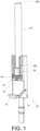
- an adjustment device 20 can include a base 22, a driving member 24 and an adjusting member 26.
- the adjustment device 20 can be applied for a working member 28, and the working member 28 can be a rod body; however, application of the working member 28 is not limited to the foresaid embodiment, and depends on a design demand.
- the adjusting member 26 and/or the driving member 24 can be arranged on the base 22; therefore, in one possible embodiment, the adjusting member 26 and the driving member 24 can be both arranged on the base 22.
- the base 22 can include a space configured to accommodate the driving member 24 and the adjusting member 26.
- the space can include a first space portion S1 and a second space portion S2 communicated with each other.
- the first space portion S1 can be used to accommodate the driving member 24 and a part of the working member 28, such as an end portion or a first end portion 28a of the working member 28.
- the second space portion S2 can be used to accommodate a part of the adjusting member 26.
- the first end portion 28a of the working member 28 can correspond to or align with the driving member 24; moreover, the first end portion 28a of the working member 28 can abut against the driving member 24.
- the first end portion 28a of the working member 28 can be connected with the driving member 24 (such as in a fixed manner).
- Application of the first end portion 28a of the working member 28 and the driving member 24 is not limited to the foresaid embodiments, and depends on the design demand.
- the adjusting member 26 can be screwed to the driving member 24.
- the adjusting member 26 can include a connecting portion 30 and an adjusting portion 32, and the adjusting portion 32 can be connected to the connecting portion 30;
- the driving member 24 can include a corresponding portion 34 configured to be screwed to the connecting portion 30 of the adjusting member 26.
- the corresponding portion 34 of the driving member 24 and the connecting portion 30 of the adjusting member 26 can have screwed features that can be engaged with each other.
- the adjusting portion 32 of the adjusting member 26 can be accommodated inside the second space portion S2, and the connecting portion 30 of the adjusting member 26 can be accommodated inside the first space portion S1.
- the base 22 can further include a mounting portion 29, and the adjusting member 26 can further include a stretching portion 33 configured to pierce through the mounting portion 29.
- the adjusting portion 32 can be located between the stretching portion 33 and the connecting portion 30.
- the first space portion S1 can be a channel with a predefined length, and the first space portion S1 can be formed by a first preset wall 36, a second preset wall 38 and a middle wall 40 of the base 22.
- the middle wall 40 can be located between the first preset wall 36 and the second preset wall 38, and the first preset wall 36 and the second preset wall 38 can be substantially connected to the middle wall 40 in a vertical manner.
- the base 22 can include at least one constraining portion 42 configured to constrain a movement of the driving member 24, and the at least one constraining portion 42 can be located on one of the first preset wall 36, the second preset wall 38 and the middle wall 40.
- the at least one constraining portion 42 is located on middle wall 40; however, application of position of the at least one constraining portion 42 is not limited to the foresaid embodiment, and depends on the design demand.
- the at least one constraining portion 42 can be a protrusion; moreover, the at least one constraining portion 42 can be the protrusion of a resilient arm 43, and the resilient arm 43 can be arranged on the middle wall 40; application of the resilient arm 43 is not limited to the foresaid embodiment, and depends on the design demand.
- the resilient arm 43 can further include a guiding section 45, and the guiding section 45 can be an inclined surface or an arc surface, which can be shown in FIG. 5 .
- the resilient arm 43 can be pressed by the driving member 24 via guide of the guiding section 45, and the resilient arm 43 can store a resilient force; when the driving member 24 is shifted across the resilient arm 43, the resilient force of the resilient arm 43 can be released, and the driving member 24 can be constrained inside the first space portion S 1 by the at least one constraining portion 42, so that the driving member 24 can be only allowed to move within a specific range.
- the adjusting member 26 can be configured to adjust the movement of the driving member 24.
- the adjusting member can adjust the movement of the driving member 24 in a rotatable manner.
- the user can apply a force to the adjusting portion 32, and the adjusting member 26 can be rotated in a first rotation direction R1 and configured to move the driving member 24 with respect to the base 22 from a first preset position P1 (which can be shown in FIG. 3 ) in a first direction D1, such as moving to a second preset position P2 (which can be shown in FIG. 4 and FIG.
- the driving member 24 can be shifted in a linear manner.
- the at least one constraining portion 42 can be configured to block the driving member 24 at the second preset position P2 (which can be shown in FIG. 5 ) for constraint effect.
- first preset position P1 and the second preset position P2 can be two extreme positions of the driving member 24; moreover, the first preset position P1 and the second preset position P2 can be any two possible positions within an activity range of the driving member 24.
- Application of the first preset position P1 and the second preset position P2 is not limited to the foresaid embodiment, and depends on the design demand.
- the working member 28 can be arranged between the adjustment device 20 and an auxiliary device 44.
- the first end portion 28a of the working member 28 can be connected to the adjustment device 20, and another end portion or a second end portion 28b of the working member 28 can be connected to the auxiliary device 44.
- Position of the second end portion 28b can correspond to position of the first end portion 28a.
- the adjustment device 20 can have structural configuration substantially the same as structural configuration of the auxiliary device 44, and principle of the auxiliary device 44 for moving the working member 28 in the first direction D1 or in the second direction D2 can be substantially the same as principle of the adjustment device 20 for adjusting the working member 28, which can be shown in FIG. 3 and FIG. 4 , and therefore a detailed description can be omitted herein for simplicity; that is to say, the auxiliary device 44 can be interpreted as another adjustment device.
- the user can adjust the working member 28 to move in the first direction D1 or in the second direction D2 via the adjustment device 20 (or the adjusting member 26) arranged on the first end portion 28a of the working member 28; further, the user can adjust the working member 28 to move in the first direction D1 or in the second direction D2 via the auxiliary device 44 (or the adjusting member 46) arranged on the second end portion 28b of the working member 28, so that the adjustment device 20 and the auxiliary device 44 can have an advantage of convenient operation.
- the adjustment device 20, the working member 28 and the auxiliary device 44 can be preferably configured to form an interlock mechanism.
- the interlock mechanism can be applied for the slide rail mechanism 48, and one slide rail assembly of the slide rail mechanism 48 can be locked due to a movement of another slide rail assembly of the slide rail mechanism 48, which means the slide rail mechanism 48 can have an interlock function.
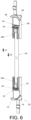
- the slide rail mechanism 48 can include a first slide rail assembly 50, a second slide rail assembly 52, the adjustment device 20, the working member 28 and the auxiliary device 44.
- the first slide rail assembly 50 can include a first rail 54 and a second rail 56, and the second rail 56 can be shiftable with respect to the first rail 54 in a longitudinal direction; preferably, the first slide rail assembly 50 can further include a first middle rail 58 movably mounted between the first rail 54 and the second rail 56.
- the second slide rail assembly 52 can include a third rail 60 and a fourth rail 62, and the fourth rail 62 can be shiftable with respect to the third rail 60 in the longitudinal direction; preferably, the second slide rail assembly 52 can further include a second middle rail 64 movably mounted between the third rail 60 and the fourth rail 62.
- the adjustment device 20 can be movably mounted on the first slide rail assembly 50.
- the first rail 54 can include a first wall 66a, a second wall 66b and a vertical wall 68.
- the vertical wall 68 can be connected between the first wall 66a and the second wall 66b of the first rail 54.
- the first rail 54 can have a first end 54a and a second end 54b, such as a front end and a rear end, and application of the foresaid ends can depend on the design demand.
- the first rail 54 can further include a first accommodating space K1 configured to accommodate the adjustment device 20.
- the first accommodating space K1 can be arranged by the first wall 66a, the second wall 66b and the vertical wall 68 of the first rail 54, the first accommodating space K1 can be adjacent to the first end 54a of the first rail 54, and the adjustment device 20 can be adjacent to the first wall 66a of the first rail 54.
- the base 22 of the adjustment device 20 can include a first constraining feature 70 configured to correspond to the first wall 66a of the first rail 54, and further to constrain the movement of the adjustment device 20 with respect to the first rail 54 at an extreme position.
- one of the second rail 56 and the adjustment device 20 can include a guiding feature, such as the inclined surface or the arc surface, and application of the guiding feature can depend on the design demand. Therefore, in one possible example, a first guiding feature 72 can be arranged on the second rail 56, and the base 22 of the adjustment device 20 can include a second guiding feature 74.
- the auxiliary device 44 can be movably mounted on the second slide rail assembly 52.
- the third rail 60 can include a first wall 76a, a second wall 76b and a vertical wall 78.
- the vertical wall 78 can be connected between the first wall 76a and the second wall 76b of the third rail 60.
- the third rail 60 can have a first end 60a and a second end 60b, such as the front end and the rear end, and application of the foresaid ends can depend on the design demand.
- the third rail 60 can further include a second accommodating space K2 configured to accommodate the auxiliary device 44.
- the second accommodating space K2 can be arranged by the first wall 76a, the second wall 76b and the vertical wall 78 of the third rail 60, the second accommodating space K2 can be adjacent to the first end 60a of the third rail 60, and the auxiliary device 44 can be adjacent to the second wall 76b of the third rail 60.
- the base 80 of the auxiliary device 44 can include a second constraining feature 82 configured to correspond to the second wall 76b of the third rail 60, and further to constrain the movement of the auxiliary device 44 with respect to the third rail 60 at the extreme position.
- one of the fourth rail 62 and the auxiliary device 44 can include the guiding feature, such as the inclined surface or the arc surface, and application of the guiding feature can depend on the design demand. Therefore, in one possible example, a third guiding feature 84 can be arranged on the fourth rail 62, and the base 80 of the auxiliary device 44 can include a fourth guiding feature 86.
- the interlock mechanism can be located at a first position J1. Further, when the second rail 56 is set in the retracted position with respect to the first rail 54, and the fourth rail 62 is set in the retracted position with respect to the third rail 60, the interlock mechanism can be located at the first position J1; in the meantime, the fourth rail 62 of the second slide rail assembly 52 is not blocked by the auxiliary device 44.
- the adjustment device 20 and the working member 28 and the auxiliary device 44 are linked for utilizing the auxiliary device 44 to block the fourth rail 62 (which can be shown in FIG. 8 ), so as to prevent the fourth rail 62 from being shifted with respect to the third rail 60 in the actuation direction E.
- the first guiding feature 72 of the second rail 56 can abut against the adjustment device 20 (such as abutting against the second guiding feature 74) to generate a force for driving the adjustment device 20, the working member 28 and the auxiliary device 44 from the first position J1 (which can be shown in FIG. 7 ) to a second position J2 (which can be shown in FIG. 8 ) in the first direction D1.
- the auxiliary device 44 and the fourth rail 62 can be blocked by each other at the second position J2, for example, the fourth guiding feature 86 of the auxiliary device 44 can be configured to block the third guiding feature 84 of the fourth rail 62, so as to prevent the fourth rail 62 from being shifted with respect to the third rail 60 from the retracted position in the actuation direction E.
- the second rail 56 (or a wall 88 of the first middle rail 58) can be configured to hold the adjustment device 20 and further to keep the interlock mechanism at the second position J2 (which can be shown in FIG. 8 ), and therefore the fourth guiding feature 86 of the auxiliary device 44 can be used to block the third guiding feature 84 of the fourth rail 62.
- the adjustment device 20 (or the auxiliary device 44) of the embodiment can have an adjustment mechanism configured to adjust the movement of the working member 28 for eliminating tolerance effect.
- the working member 28 can be drivable in response to the movement of the adjusting member 26 of the adjustment device 20.
- the user can apply the force to the adjusting portion 32 of the adjusting member 26, for adjusting the movement of the driving member 24 with respect to the base 22.
- the driving member 24 can be shifted from the first preset position P1 (which can be shown in FIG. 8 ) in the first direction D1 (which can be shown in FIG. 9 ), and the working member 28 can be shifted from the first corresponding position in the first direction D1, so that the auxiliary device 44 and the fourth rail 62 can be blocked by each other more tightly.
- P1 which can be shown in FIG. 8
- D1 which can be shown in FIG. 9
- the fourth guiding feature 86 of the auxiliary device 44 (which is shown in FIG. 9 ) can be near to the third guiding feature 84 of the fourth rail 62; besides, the user may apply another force to the adjusting portion 32 of the adjusting member 26 for adjusting the movement of the driving member 24 with respect to the base 22 in the second direction D2, and the working member 28 can be shifted in the second direction D2, so that contact between the auxiliary device 44 and the fourth rail 62 can be gradually weakened.
- the fourth guiding feature 86 of the auxiliary device 44 (which is shown in FIG. 8 ) can be distant from the third guiding feature 84 of the fourth rail 62. Therefore, the interlock mechanism of the present application can be more reliable due to foresaid description.
- the auxiliary device 44 of the interlock mechanism which is located at the first position J1 can be pressed by the fourth rail 62 (or the second middle rail 64) of the second slide rail assembly 52, so that the second rail 56(or the related first guiding feature 72) of the first slide rail assembly 50 can be blocked by the adjustment device 20 (or the related second guiding feature 74), so as to prevent the second rail 56 from being shifted with respect to the first rail 54 from the retracted position in the actuation direction E.
- the user can utilize the auxiliary device 44 (or the related adjusting member 46) to adjust the movement of the working member 28, so as to accordingly adjust tightness between the adjustment device 20 (or the related second guiding feature 74) and the second rail 56 (or the related first guiding feature 72), for making the interlock mechanism more reliable in the same way as mentioned above; thus, the detailed description is omitted herein for simplicity.
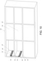
- the first slide rail assembly 50 and the second slide rail assembly 52 can be arranged on a cabinet 90.
- the cabinet 90 can include a plurality of holders 92 (such as drawers).
- the first rail 54 o the first slide rail assembly 50 can be fixed onto the cabinet 90, and the second rail 56 can be configured to hold a first holder (such as a first drawer not shown in the figures).
- the third rail 60 of the second slide rail assembly 52 can be fixed onto the cabinet 90, and the fourth rail 62 can be configured to hold a second holder (such as a second drawer not shown in the figures).
- the adjustment device 20, the working member 28 and the auxiliary device 44 can be located between the first slide rail assembly 50 and the second slide rail assembly 52 for operation of the interlock mechanism, and one of the adjustment device 20 and the auxiliary device 44 can be configured to adjust the movement of the working member 28; principle of the foresaid members is disclosed in FIG. 7 to FIG. 9 , and the detailed description is omitted herein for simplicity.
- the adjusting member 26 of the adjustment device 20 (or the adjusting member 46 of the auxiliary device 44) can be configured to adjust the movement of the working member 28, so as to avoid functional quality of the interlock mechanism from being affected by the length tolerance of the working member 28, or further to adjust the tightness between the interlock mechanism and the slide rail assembly that is blocked by each other; it is to say, product quality of the interlock mechanism and the slide rail assembly can be improved accordingly.
- the slide rail mechanism and the adjustment device provided by the embodiment of the present application can have following advantages:
Landscapes
- Engineering & Computer Science (AREA)
- Structural Engineering (AREA)
- Drawers Of Furniture (AREA)
- Seats For Vehicles (AREA)
- Forklifts And Lifting Vehicles (AREA)
- Manipulator (AREA)
Applications Claiming Priority (1)
| Application Number | Priority Date | Filing Date | Title |
|---|---|---|---|
| TW112110145A TWI822613B (zh) | 2023-03-16 | 2023-03-16 | 滑軌機構及其調整裝置 |
Publications (2)
| Publication Number | Publication Date |
|---|---|
| EP4431684A1 true EP4431684A1 (de) | 2024-09-18 |
| EP4431684B1 EP4431684B1 (de) | 2025-09-10 |
Family
ID=87196202
Family Applications (1)
| Application Number | Title | Priority Date | Filing Date |
|---|---|---|---|
| EP23184168.5A Active EP4431684B1 (de) | 2023-03-16 | 2023-07-07 | Gleitschienenmechanismus und einstellvorrichtung dafür |
Country Status (4)
| Country | Link |
|---|---|
| US (1) | US12366093B2 (de) |
| EP (1) | EP4431684B1 (de) |
| JP (1) | JP7547716B1 (de) |
| TW (1) | TWI822613B (de) |
Families Citing this family (2)
| Publication number | Priority date | Publication date | Assignee | Title |
|---|---|---|---|---|
| CN220889859U (zh) * | 2023-08-28 | 2024-05-03 | 昆山湖华金属制品有限公司 | 用于多层式抽屉家具的连环锁机构 |
| TWI863863B (zh) | 2024-05-06 | 2024-11-21 | 川湖科技股份有限公司 | 滑軌機構及其調整裝置 |
Citations (4)
| Publication number | Priority date | Publication date | Assignee | Title |
|---|---|---|---|---|
| US5333949A (en) | 1992-10-05 | 1994-08-02 | Krueger International, Inc. | File drawer interlock mechanism |
| EP3064680A1 (de) * | 2009-04-08 | 2016-09-07 | Paul Hettich GmbH & Co. KG | Verriegelungsanordnung und möbel |
| CN217510123U (zh) * | 2022-04-01 | 2022-09-30 | 清远市星徽精密制造有限公司 | 一种具有自锁互锁功能的抽屉导轨 |
| CN218074140U (zh) * | 2022-07-23 | 2022-12-20 | 清远市星徽精密制造有限公司 | 一种具有调节互锁松紧度功能的双锁式导轨 |
Family Cites Families (20)
| Publication number | Priority date | Publication date | Assignee | Title |
|---|---|---|---|---|
| US533949A (en) | 1895-02-12 | fogebty | ||
| JPH08906Y2 (ja) | 1991-12-13 | 1996-01-17 | 高橋金物株式会社 | 引出しの化粧板調整部材 |
| US6296332B1 (en) * | 1996-07-12 | 2001-10-02 | Accuride International, Inc. | File interlock system and mechanism |
| DE69715980T2 (de) | 1996-07-12 | 2003-01-30 | Accuride International, Inc. | Verriegelungssystem mit Stangenverschluss für Schubladen |
| GB2380516B (en) * | 2001-10-05 | 2005-07-27 | Accuride Int Ltd | Rear interlock |
| US6543318B1 (en) * | 2001-11-15 | 2003-04-08 | Kennametal Inc. | Locking assembly |
| DE10212476B4 (de) * | 2002-03-20 | 2004-06-17 | Niemann, Hans Dieter | Verstelleinrichtung eines Drehbandes von Türen oder Fenstern |
| US7334293B2 (en) * | 2005-02-16 | 2008-02-26 | Newell Operating Company | Vertically adjustable hinge |
| US7101001B1 (en) * | 2005-06-13 | 2006-09-05 | I Hsiang Chiu | Coupling device preventing two drawers from being pulled out simultaneously |
| US7695080B2 (en) * | 2007-06-05 | 2010-04-13 | King Slide Works Co., Ltd. | Securing device for a drawer slide |
| FR2921683B1 (fr) * | 2007-09-28 | 2012-08-24 | Tordo Belgrano Sa | Dispositif de montage d'une patte d'articulation pour vantail sur un gond. |
| US7823992B2 (en) | 2007-12-19 | 2010-11-02 | King Slide Works Co., Ltd. | Drawer interlock mechanism |
| US8308251B2 (en) * | 2010-05-20 | 2012-11-13 | King Slide Works Co., Ltd. | Elastic force adjustment device for slide assembly |
| US8540328B2 (en) * | 2011-01-05 | 2013-09-24 | King Slide Works Co., Ltd. | Control mechanism for drawer slide assembly |
| JP3236470U (ja) | 2021-12-22 | 2022-02-18 | 怡君 陳 | スライドレールロックロッド式の引き出しにおける転倒防止安全装置 |
| CN115104867A (zh) * | 2022-04-01 | 2022-09-27 | 清远市星徽精密制造有限公司 | 一种具有自锁互锁功能的抽屉导轨 |
| CN116115023A (zh) * | 2022-09-08 | 2023-05-16 | 清远市星徽精密制造有限公司 | 一种具有锁住功能的抽屉互锁导轨 |
| TWI849709B (zh) * | 2023-01-19 | 2024-07-21 | 川湖科技股份有限公司 | 滑軌機構 |
| CN118415458A (zh) * | 2023-02-01 | 2024-08-02 | 川湖科技股份有限公司 | 滑轨机构 |
| CN116831400B (zh) * | 2023-06-09 | 2026-04-28 | 佛山市瑞易德塑料五金制品有限公司 | 一种具有抽屉互锁功能的家具 |
-
2023
- 2023-03-16 TW TW112110145A patent/TWI822613B/zh active
- 2023-05-24 US US18/201,721 patent/US12366093B2/en active Active
- 2023-06-16 JP JP2023099391A patent/JP7547716B1/ja active Active
- 2023-07-07 EP EP23184168.5A patent/EP4431684B1/de active Active
Patent Citations (4)
| Publication number | Priority date | Publication date | Assignee | Title |
|---|---|---|---|---|
| US5333949A (en) | 1992-10-05 | 1994-08-02 | Krueger International, Inc. | File drawer interlock mechanism |
| EP3064680A1 (de) * | 2009-04-08 | 2016-09-07 | Paul Hettich GmbH & Co. KG | Verriegelungsanordnung und möbel |
| CN217510123U (zh) * | 2022-04-01 | 2022-09-30 | 清远市星徽精密制造有限公司 | 一种具有自锁互锁功能的抽屉导轨 |
| CN218074140U (zh) * | 2022-07-23 | 2022-12-20 | 清远市星徽精密制造有限公司 | 一种具有调节互锁松紧度功能的双锁式导轨 |
Also Published As
| Publication number | Publication date |
|---|---|
| US20240309681A1 (en) | 2024-09-19 |
| US12366093B2 (en) | 2025-07-22 |
| TWI822613B (zh) | 2023-11-11 |
| EP4431684B1 (de) | 2025-09-10 |
| TW202437959A (zh) | 2024-10-01 |
| JP2024132776A (ja) | 2024-10-01 |
| JP7547716B1 (ja) | 2024-09-10 |
Similar Documents
| Publication | Publication Date | Title |
|---|---|---|
| EP4431684A1 (de) | Gleitschienenmechanismus und einstellvorrichtung dafür | |
| EP3387952B1 (de) | Gleitschienenanordnung | |
| US8430889B2 (en) | Puncture needle holder | |
| KR102012573B1 (ko) | 가구 구동 장치 | |
| EP3932257B1 (de) | Möbelsystem | |
| US7883162B2 (en) | Device for influencing the movement of furniture parts which can be moved with respect to one another, and piece of furniture | |
| JP5566311B2 (ja) | 家具用の引き込み装置 | |
| EP3372117B1 (de) | Kopplungsmechanismus und gleitschienenanordnung mit dämpfungsfunktion | |
| EP3332670B1 (de) | Vorrichtung für die verstellbare halterung von ausziehführungen an schubladen | |
| US10470569B2 (en) | Coupling mechanism and slide rail assembly for furniture part | |
| CN101248244A (zh) | 缓冲元件 | |
| EP4321053B1 (de) | Schienenanordnung | |
| EP3530147B1 (de) | Gleitschienenanordnung | |
| EP3372115B1 (de) | Kopplungsmechanismus und gleitschienenanordnung für möbelteil | |
| CN116783361A (zh) | 用于相对于家具主体引导至少一个门扇的引导系统 | |
| EP3372116B1 (de) | Möbel mit einzugsmechanismus | |
| CN118686499A (zh) | 滑轨机构及其调整装置 | |
| CN107581807B (zh) | 安装机构 | |
| CN119697935B (zh) | 滑轨总成 | |
| CN106820676A (zh) | 安装机构 | |
| EP3449767B1 (de) | Vorrichtung für die verstellbare halterung von ausziehführungen an schubladen | |
| GB2338646A (en) | Backrest slider mechanism | |
| EP4736711A1 (de) | Gleitschienenanordnung | |
| US12064113B2 (en) | Anti-buckling actuation members for a surgical instrument | |
| EP4581983A1 (de) | Gleitschienenmechanismus |
Legal Events
| Date | Code | Title | Description |
|---|---|---|---|
| PUAI | Public reference made under article 153(3) epc to a published international application that has entered the european phase |
Free format text: ORIGINAL CODE: 0009012 |
|
| STAA | Information on the status of an ep patent application or granted ep patent |
Free format text: STATUS: REQUEST FOR EXAMINATION WAS MADE |
|
| 17P | Request for examination filed |
Effective date: 20240812 |
|
| AK | Designated contracting states |
Kind code of ref document: A1 Designated state(s): AL AT BE BG CH CY CZ DE DK EE ES FI FR GB GR HR HU IE IS IT LI LT LU LV MC ME MK MT NL NO PL PT RO RS SE SI SK SM TR |
|
| GRAP | Despatch of communication of intention to grant a patent |
Free format text: ORIGINAL CODE: EPIDOSNIGR1 |
|
| STAA | Information on the status of an ep patent application or granted ep patent |
Free format text: STATUS: GRANT OF PATENT IS INTENDED |
|
| RIC1 | Information provided on ipc code assigned before grant |
Ipc: E05B 65/464 20170101ALI20250328BHEP Ipc: A47B 88/40 20170101ALI20250328BHEP Ipc: E05B 63/00 20060101AFI20250328BHEP |
|
| INTG | Intention to grant announced |
Effective date: 20250502 |
|
| GRAS | Grant fee paid |
Free format text: ORIGINAL CODE: EPIDOSNIGR3 |
|
| GRAA | (expected) grant |
Free format text: ORIGINAL CODE: 0009210 |
|
| STAA | Information on the status of an ep patent application or granted ep patent |
Free format text: STATUS: THE PATENT HAS BEEN GRANTED |
|
| AK | Designated contracting states |
Kind code of ref document: B1 Designated state(s): AL AT BE BG CH CY CZ DE DK EE ES FI FR GB GR HR HU IE IS IT LI LT LU LV MC ME MK MT NL NO PL PT RO RS SE SI SK SM TR |
|
| REG | Reference to a national code |
Ref country code: GB Ref legal event code: FG4D |
|
| REG | Reference to a national code |
Ref country code: CH Ref legal event code: EP |
|
| REG | Reference to a national code |
Ref country code: DE Ref legal event code: R096 Ref document number: 602023006511 Country of ref document: DE |
|
| REG | Reference to a national code |
Ref country code: IE Ref legal event code: FG4D |
|
| PG25 | Lapsed in a contracting state [announced via postgrant information from national office to epo] |
Ref country code: NO Free format text: LAPSE BECAUSE OF FAILURE TO SUBMIT A TRANSLATION OF THE DESCRIPTION OR TO PAY THE FEE WITHIN THE PRESCRIBED TIME-LIMIT Effective date: 20251210 |
|
| REG | Reference to a national code |
Ref country code: LT Ref legal event code: MG9D |
|
| PG25 | Lapsed in a contracting state [announced via postgrant information from national office to epo] |
Ref country code: FI Free format text: LAPSE BECAUSE OF FAILURE TO SUBMIT A TRANSLATION OF THE DESCRIPTION OR TO PAY THE FEE WITHIN THE PRESCRIBED TIME-LIMIT Effective date: 20250910 |
|
| REG | Reference to a national code |
Ref country code: NL Ref legal event code: MP Effective date: 20250910 |
|
| PG25 | Lapsed in a contracting state [announced via postgrant information from national office to epo] |
Ref country code: HR Free format text: LAPSE BECAUSE OF FAILURE TO SUBMIT A TRANSLATION OF THE DESCRIPTION OR TO PAY THE FEE WITHIN THE PRESCRIBED TIME-LIMIT Effective date: 20250910 |
|
| PG25 | Lapsed in a contracting state [announced via postgrant information from national office to epo] |
Ref country code: GR Free format text: LAPSE BECAUSE OF FAILURE TO SUBMIT A TRANSLATION OF THE DESCRIPTION OR TO PAY THE FEE WITHIN THE PRESCRIBED TIME-LIMIT Effective date: 20251211 |
|
| PG25 | Lapsed in a contracting state [announced via postgrant information from national office to epo] |
Ref country code: SE Free format text: LAPSE BECAUSE OF FAILURE TO SUBMIT A TRANSLATION OF THE DESCRIPTION OR TO PAY THE FEE WITHIN THE PRESCRIBED TIME-LIMIT Effective date: 20250910 |
|
| PG25 | Lapsed in a contracting state [announced via postgrant information from national office to epo] |
Ref country code: LV Free format text: LAPSE BECAUSE OF FAILURE TO SUBMIT A TRANSLATION OF THE DESCRIPTION OR TO PAY THE FEE WITHIN THE PRESCRIBED TIME-LIMIT Effective date: 20250910 |
|
| PG25 | Lapsed in a contracting state [announced via postgrant information from national office to epo] |
Ref country code: BG Free format text: LAPSE BECAUSE OF FAILURE TO SUBMIT A TRANSLATION OF THE DESCRIPTION OR TO PAY THE FEE WITHIN THE PRESCRIBED TIME-LIMIT Effective date: 20250910 Ref country code: PL Free format text: LAPSE BECAUSE OF FAILURE TO SUBMIT A TRANSLATION OF THE DESCRIPTION OR TO PAY THE FEE WITHIN THE PRESCRIBED TIME-LIMIT Effective date: 20250910 |
|
| PG25 | Lapsed in a contracting state [announced via postgrant information from national office to epo] |
Ref country code: RS Free format text: LAPSE BECAUSE OF FAILURE TO SUBMIT A TRANSLATION OF THE DESCRIPTION OR TO PAY THE FEE WITHIN THE PRESCRIBED TIME-LIMIT Effective date: 20251210 |
|
| PG25 | Lapsed in a contracting state [announced via postgrant information from national office to epo] |
Ref country code: ES Free format text: LAPSE BECAUSE OF FAILURE TO SUBMIT A TRANSLATION OF THE DESCRIPTION OR TO PAY THE FEE WITHIN THE PRESCRIBED TIME-LIMIT Effective date: 20250910 |
|
| REG | Reference to a national code |
Ref country code: AT Ref legal event code: MK05 Ref document number: 1836041 Country of ref document: AT Kind code of ref document: T Effective date: 20250910 |
|
| PG25 | Lapsed in a contracting state [announced via postgrant information from national office to epo] |
Ref country code: NL Free format text: LAPSE BECAUSE OF FAILURE TO SUBMIT A TRANSLATION OF THE DESCRIPTION OR TO PAY THE FEE WITHIN THE PRESCRIBED TIME-LIMIT Effective date: 20250910 |
|
| PG25 | Lapsed in a contracting state [announced via postgrant information from national office to epo] |
Ref country code: SM Free format text: LAPSE BECAUSE OF FAILURE TO SUBMIT A TRANSLATION OF THE DESCRIPTION OR TO PAY THE FEE WITHIN THE PRESCRIBED TIME-LIMIT Effective date: 20250910 |
|
| PG25 | Lapsed in a contracting state [announced via postgrant information from national office to epo] |
Ref country code: AT Free format text: LAPSE BECAUSE OF FAILURE TO SUBMIT A TRANSLATION OF THE DESCRIPTION OR TO PAY THE FEE WITHIN THE PRESCRIBED TIME-LIMIT Effective date: 20250910 |
|
| PG25 | Lapsed in a contracting state [announced via postgrant information from national office to epo] |
Ref country code: IT Free format text: LAPSE BECAUSE OF FAILURE TO SUBMIT A TRANSLATION OF THE DESCRIPTION OR TO PAY THE FEE WITHIN THE PRESCRIBED TIME-LIMIT Effective date: 20250910 |
|
| PG25 | Lapsed in a contracting state [announced via postgrant information from national office to epo] |
Ref country code: IS Free format text: LAPSE BECAUSE OF FAILURE TO SUBMIT A TRANSLATION OF THE DESCRIPTION OR TO PAY THE FEE WITHIN THE PRESCRIBED TIME-LIMIT Effective date: 20260110 |
|
| PG25 | Lapsed in a contracting state [announced via postgrant information from national office to epo] |
Ref country code: PT Free format text: LAPSE BECAUSE OF FAILURE TO SUBMIT A TRANSLATION OF THE DESCRIPTION OR TO PAY THE FEE WITHIN THE PRESCRIBED TIME-LIMIT Effective date: 20260112 Ref country code: CZ Free format text: LAPSE BECAUSE OF FAILURE TO SUBMIT A TRANSLATION OF THE DESCRIPTION OR TO PAY THE FEE WITHIN THE PRESCRIBED TIME-LIMIT Effective date: 20250910 |
|
| PG25 | Lapsed in a contracting state [announced via postgrant information from national office to epo] |
Ref country code: EE Free format text: LAPSE BECAUSE OF FAILURE TO SUBMIT A TRANSLATION OF THE DESCRIPTION OR TO PAY THE FEE WITHIN THE PRESCRIBED TIME-LIMIT Effective date: 20250910 Ref country code: SK Free format text: LAPSE BECAUSE OF FAILURE TO SUBMIT A TRANSLATION OF THE DESCRIPTION OR TO PAY THE FEE WITHIN THE PRESCRIBED TIME-LIMIT Effective date: 20250910 |