EP4431666A1 - Work machine - Google Patents
Work machine Download PDFInfo
- Publication number
- EP4431666A1 EP4431666A1 EP22892494.0A EP22892494A EP4431666A1 EP 4431666 A1 EP4431666 A1 EP 4431666A1 EP 22892494 A EP22892494 A EP 22892494A EP 4431666 A1 EP4431666 A1 EP 4431666A1
- Authority
- EP
- European Patent Office
- Prior art keywords
- pattern
- lever
- switching lever
- switch
- switching
- Prior art date
- Legal status (The legal status is an assumption and is not a legal conclusion. Google has not performed a legal analysis and makes no representation as to the accuracy of the status listed.)
- Pending
Links
Images







Classifications
-
- E—FIXED CONSTRUCTIONS
- E02—HYDRAULIC ENGINEERING; FOUNDATIONS; SOIL SHIFTING
- E02F—DREDGING; SOIL-SHIFTING
- E02F3/00—Dredgers; Soil-shifting machines
- E02F3/04—Dredgers; Soil-shifting machines mechanically-driven
- E02F3/28—Dredgers; Soil-shifting machines mechanically-driven with digging tools mounted on a dipper- or bucket-arm, i.e. there is either one arm or a pair of arms, e.g. dippers, buckets
- E02F3/30—Dredgers; Soil-shifting machines mechanically-driven with digging tools mounted on a dipper- or bucket-arm, i.e. there is either one arm or a pair of arms, e.g. dippers, buckets with a dipper-arm pivoted on a cantilever beam, i.e. boom
- E02F3/32—Dredgers; Soil-shifting machines mechanically-driven with digging tools mounted on a dipper- or bucket-arm, i.e. there is either one arm or a pair of arms, e.g. dippers, buckets with a dipper-arm pivoted on a cantilever beam, i.e. boom working downwardly and towards the machine, e.g. with backhoes
- E02F3/325—Backhoes of the miniature type
-
- E—FIXED CONSTRUCTIONS
- E02—HYDRAULIC ENGINEERING; FOUNDATIONS; SOIL SHIFTING
- E02F—DREDGING; SOIL-SHIFTING
- E02F9/00—Component parts of dredgers or soil-shifting machines, not restricted to one of the kinds covered by groups E02F3/00 - E02F7/00
- E02F9/16—Cabins, platforms, or the like, for drivers
- E02F9/166—Cabins, platforms, or the like, for drivers movable, tiltable or pivoting, e.g. movable seats, dampening arrangements of cabins
-
- E—FIXED CONSTRUCTIONS
- E02—HYDRAULIC ENGINEERING; FOUNDATIONS; SOIL SHIFTING
- E02F—DREDGING; SOIL-SHIFTING
- E02F9/00—Component parts of dredgers or soil-shifting machines, not restricted to one of the kinds covered by groups E02F3/00 - E02F7/00
- E02F9/20—Drives; Control devices
- E02F9/2004—Control mechanisms, e.g. control levers
-
- E—FIXED CONSTRUCTIONS
- E02—HYDRAULIC ENGINEERING; FOUNDATIONS; SOIL SHIFTING
- E02F—DREDGING; SOIL-SHIFTING
- E02F9/00—Component parts of dredgers or soil-shifting machines, not restricted to one of the kinds covered by groups E02F3/00 - E02F7/00
- E02F9/20—Drives; Control devices
- E02F9/2004—Control mechanisms, e.g. control levers
- E02F9/2012—Setting the functions of the control levers, e.g. changing assigned functions among operations levers, setting functions dependent on the operator or seat orientation
-
- E—FIXED CONSTRUCTIONS
- E02—HYDRAULIC ENGINEERING; FOUNDATIONS; SOIL SHIFTING
- E02F—DREDGING; SOIL-SHIFTING
- E02F9/00—Component parts of dredgers or soil-shifting machines, not restricted to one of the kinds covered by groups E02F3/00 - E02F7/00
- E02F9/20—Drives; Control devices
- E02F9/22—Hydraulic or pneumatic drives
- E02F9/2203—Arrangements for controlling the attitude of actuators, e.g. speed, floating function
-
- E—FIXED CONSTRUCTIONS
- E02—HYDRAULIC ENGINEERING; FOUNDATIONS; SOIL SHIFTING
- E02F—DREDGING; SOIL-SHIFTING
- E02F9/00—Component parts of dredgers or soil-shifting machines, not restricted to one of the kinds covered by groups E02F3/00 - E02F7/00
- E02F9/20—Drives; Control devices
- E02F9/22—Hydraulic or pneumatic drives
- E02F9/2278—Hydraulic circuits
- E02F9/2285—Pilot-operated systems
-
- E—FIXED CONSTRUCTIONS
- E02—HYDRAULIC ENGINEERING; FOUNDATIONS; SOIL SHIFTING
- E02F—DREDGING; SOIL-SHIFTING
- E02F9/00—Component parts of dredgers or soil-shifting machines, not restricted to one of the kinds covered by groups E02F3/00 - E02F7/00
- E02F9/20—Drives; Control devices
- E02F9/22—Hydraulic or pneumatic drives
- E02F9/2221—Control of flow rate; Load sensing arrangements
- E02F9/2225—Control of flow rate; Load sensing arrangements using pressure-compensating valves
Definitions
- the present invention relates to a working machine.
- Patent Literature 1 A working machine disclosed in Patent Literature 1 (PTL 1) is known.
- the working machine disclosed in PTL 1 is provided with a plurality of hydraulic actuators.
- a manual operator that operates the plurality of hydraulic actuators is provided beside an operator's seat mounted on a machine body.
- a pattern switch that switches an operation pattern of the manual operator for the plurality of hydraulic actuators between a plurality of operation patterns is provided on the machine body. The pattern switch is provided below the operator's seat.
- an object of the present invention is to provide a working machine which has space for placement of a pattern switch even if the working machine is compact.
- a working machine is a working machine provided with a plurality of hydraulic actuators, the working machine including a machine body, an operator's seat on the machine body, a console extending upward from the machine body in front of the operator's seat; a manual operator to operate the plurality of hydraulic actuators, and a pattern switch to switch an operation pattern in which the manual operator is used to operate the plurality of hydraulic actuators between a plurality of operation patterns, wherein the console includes therein a switch placement portion for placement of the pattern switch.
- the working machine may further include a traveling device to support the machine body such that the machine body is allowed to travel, and a traveling lever to operate the traveling device, the traveling lever being provided at a substantially central portion in a machine-body width direction of an upper portion of the console.
- the console may include a support frame attached to the machine body, a cover member to cover the support frame, and a traveling lever support provided at an upper portion of the support frame to support the traveling lever.
- the switch placement portion may be located, inside the cover member, at the upper portion of the support frame such that the switch placement portion is located beside the traveling lever support in the machine-body width direction.
- the working machine may further include a control valve unit including a plurality of control valves to control the plurality of hydraulic actuators.
- the support frame may include a first side plate and a second side plate facing each other with a space therebetween in the machine-body width direction, and a coupling plate to connect upper portions of the first side plate and the second side plate.
- the control valve unit may be located below the coupling plate such that the control valve unit is located between the first side plate and the second side plate.
- the traveling lever support may be provided at a substantially central portion in the machine-body width direction of the coupling plate.
- the switch placement portion may be provided between the traveling lever support and the first side plate or the second side plate on the coupling plate.
- the console may include, in the cover member, an opening at a position corresponding to the pattern switch, and a lid member to open and close the opening.
- the plurality of operation patterns may include a first operation pattern and a second operation pattern that differs from the first operation pattern.
- the pattern switch may include a switching lever pivotable between a first operation position in which the first operation pattern is selected and a second operation position in which the second operation pattern is selected.
- the switching lever may be, in each of the first and second operation positions, movable between an extended state in which the switching lever projects through the opening and a retracted state in which the switching lever is retracted within the lid member.
- a working machine is a working machine provided with a plurality of hydraulic actuators, the working machine including a machine body, a cover member on the machine body, a manual operator to operate the plurality of hydraulic actuators, and a pattern switch to switch an operation pattern in which the manual operator is used to operate the plurality of hydraulic actuators between a plurality of operation patterns, the pattern switch being housed inside the cover member, wherein the cover member includes an opening at a position corresponding to the pattern switch, and a lid member to open and close the opening, the plurality of operation patterns include a first operation pattern and a second operation pattern, the pattern switch includes a switching lever pivotable between a first operation position in which the first operation pattern is selected and a second operation position in which the second operation pattern is selected, and the switching lever is, in each of the first and second operation positions, movable between an extended state in which the switching lever projects through the opening and a retracted state in which the switching lever is retracted within the lid member.
- the working machine may further include a contact member to, when the switching lever is within a pivoting range between the first operation position and the second operation position and is moved in a direction from the extended state toward the retracted state, come into contact with the switching lever such that the switching lever projects through the opening to stop the switching lever from moving.
- the working machine may further include a plurality of control valves to be pilot-operated by the manual operator, the plurality of control valves being provided such that the plurality of control valves correspond to the plurality of hydraulic actuators to control the plurality of hydraulic actuators.
- the pattern switch may include a pattern switching valve to switch between the plurality of operation patterns by changing a direction of a flow of pilot fluid to pilot-operate the control valves by operation of the manual operator, a pivot shaft about which the switching lever is to be pivoted, a swing arm supported such that the swing arm is pivotable about the pivot shaft and including a switching lever support to support the switching lever such that the switching lever is movable between the extended state and the retracted state, and an interlock mechanism to interlock the swing arm and a valve element of the pattern switching valve.
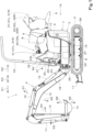
- FIG. 1 is a schematic side view of a working machine 1 according to the present embodiment.
- a compact backhoe which is a swivel working machine, is illustrated as an example of the working machine 1.
- the working machine 1 includes a travel unit 1A and a working device 4 provided on the travel unit 1A.
- the travel unit 1A includes a traveling device 3 and a machine body (swivel base) 2 on the traveling device 3.
- An operator's seat 5 on which an operator is seated is provided on the machine body 2.
- the front (direction of arrow K1 in FIG. 1 ) of the operator seated on the operator's seat 5 is described as forward
- the rear (direction of arrow K2 in FIG. 1 ) of the operator is described as rearward
- the left (near side in FIG. 1 ) of the operator is described as leftward
- the right (far side in FIG. 1 ) of the operator is described as rightward
- the direction along arrow K3 in FIG. 1 is described as a front-rear direction (machine-body front-rear direction)
- a horizontal direction perpendicular to the front-rear direction K3 is described as a machine-body width direction (width direction of the machine body 2).
- a direction from a central portion to a right portion or to a left portion along the width direction of the machine body 2 is described as a machine-body outward side (an outward side in the machine-body width direction). That is, the machine-body outward direction is one of the machine-body width directions and is a direction away from the widthwise center of the machine body 2.
- a direction opposite to the machine-body outward direction is described as a machine-body inward direction (inward direction along the machine-body width direction). That is, the machine-body inward direction is one of the machine-body width directions and is a direction toward the widthwise center of the machine body 2.
- the machine body 2 is supported by the traveling device 3 such that the machine body 2 is rotatable about a vertical axis (an axis extending in an up-down direction).
- the machine body 2 includes a swivel base plate 6 that defines a bottom portion of the machine body 2, and a weight 7 attached to a rear portion of the swivel base plate 6.
- the swivel base plate 6 is supported on a frame of the traveling device 3 via a bearing body 19 such that the swivel base plate 6 is rotatable about the vertical axis, and rotates leftward or rightward by being driven by a turning motor M1 including a hydraulic motor (hydraulic actuator).
- a step plate 26 on which the operator seated on the operator's seat 5 places their foot is located above the swivel base plate 6.
- the space between the swivel base plate 6 and the step plate 26 is covered with a side cover 27.
- the working device 4 is attached to a front portion of the machine body 2.
- the weight 7 is a counterweight to balance the weight with the working device 4.
- a ROPS 24 to protect the operator seated on the operator's seat 5 is provided above the machine body 2.
- a hood 8 is located above a rear portion of the machine body 2.
- the operator's seat 5 is located above the hood 8.
- the hood 8 can open by rotating rearward.
- the hood 8 houses therein a prime mover 10 as a drive source, a hydraulic fluid tank 9 which stores a hydraulic fluid to drive hydraulic actuators such as hydraulic cylinder(s), hydraulic motor(s), and/or the like provided in the working machine 1, a hydraulic pump (not illustrated) to suck and deliver the hydraulic fluid from the hydraulic fluid tank 9, and the like.
- a diesel engine is used as the prime mover 10 in the present embodiment, however the prime mover 10 is not limited to the diesel engine.
- the prime mover 10 may be another internal combustion engine such as a gasoline engine, or may include an electric motor and/or the like.
- the traveling device 3 is a crawler traveling device and is provided below each of right and left portions of the machine body 2. Such traveling devices 3 are driven by traveling motors 28 including hydraulic motors.
- a dozer 11 is provided at front portions of the traveling devices 3. The dozer 11 is driven by a dozer cylinder (not illustrated).
- the working device 4 includes a boom 12, an arm 13, and a bucket 14 as a working tool.
- the working device 4 further includes, as mechanisms to drive the boom and the like, a boom cylinder 15, an arm cylinder 16, and a bucket cylinder 17 as a working tool cylinder.
- the boom cylinder 15, the arm cylinder 16, the bucket cylinder 17, and the dozer cylinder include hydraulic cylinders (hydraulic actuators). These hydraulic cylinders are driven by hydraulic fluid supplied from the hydraulic fluid tank 9 via the hydraulic pump.
- the working device 4 is operated using a manipulating lever 31 (described later).
- a proximal end portion of the boom 12 is pivotally supported by a swing bracket 18 provided at the front portion of the machine body 2 such that the boom 12 is swingable about a horizontal axis.
- the swing bracket 18 is pivotally supported by a support bracket 29 provided at the machine body 2 such that the swing bracket 18 is swingable about a vertical axis.
- a swing cylinder (not illustrated) including a hydraulic cylinder is attached to the machine body 2, and the swing bracket 18 swings by being driven by the swing cylinder.
- a proximal end portion of the arm 13 is pivotally supported by a distal end portion of the boom 12 such that the arm 13 is swingable about a horizontal axis.
- the bucket 14 is attached to a distal end portion of the arm 13.
- the boom cylinder 15 couples the swing bracket 18 and a middle portion of the boom 12.
- the boom 12 swings upward/downward by extension/retraction of the boom cylinder 15.
- the boom 12 swings in a boom raising direction D1 by the retraction of the boom cylinder 15, and the boom 12 swings in a boom lowering direction D2 by the extension of the boom cylinder 15.
- the arm cylinder 16 couples the middle portion of the boom 12 and the proximal end portion of the arm 13.
- the arm 13 swings upward/downward by extension/retraction of the arm cylinder 16.
- the arm 13 swings in an arm raising direction (arm dump direction) D3 by the retraction of the arm cylinder 16, and swings in an arm lowering direction (arm crowd direction) D4 by the extension of the arm cylinder 16.
- the bucket cylinder 17 couples the proximal end portion of the arm 13 and an attachment of the bucket 14.
- the bucket 14 performs shoveling/dumping by extension/retraction of the bucket cylinder 17.
- the bucket 14 swings in a dump direction (bucket dump direction) D5 by the retraction of the bucket cylinder 17, and the bucket 14 swings in a shovel direction (bucket crowd direction) D6 by the extension of the bucket cylinder 17.
- manipulator bases 30 are provided on the left and right sides of the operator's seat 5.
- the manipulator base 30 located leftward of the operator's seat 5 is referred to as a first manipulator base 30L
- the manipulator base 30 located rightward of the operator's seat 5 is referred to as a second manipulator base 30R.
- the first manipulator base 30L has attached thereto a manual operator 31 (first manipulating lever 31L) to operate a plurality of hydraulic actuators, a remote control valve 21 (first remote control valve 21L) that is a pilot valve operated by the first manipulating lever 31L, and a first operating lever 43L to swing the first manipulator base 30L in the up-down direction.
- a manual operator 31 first manipulating lever 31L
- a remote control valve 21 first remote control valve 21L
- first operating lever 43L to swing the first manipulator base 30L in the up-down direction.
- the first manipulating lever 31L can be used to operate two objects provided in the working machine 1. Specifically, the first manipulating lever 31L can be pivoted forward, rearward, leftward, and rightward, and is used to operate one object by the forward/rearward pivot and operate another object by the leftward/rightward pivot.
- the first manipulating lever 31L is operable to, by operating the first remote control valve 21L, pilot-operate a control valve (pilot-operated switching valve) to control the corresponding object.
- a pilot fluid corresponding to the pivot amount degree of pivot of the lever
- the second manipulator base 30R has attached thereto a manual operator 31 (second manipulating lever 31R) to operate a plurality of hydraulic actuators, a remote control valve 21 (second remote control valve 21R) that is a pilot valve operated by the second manipulating lever 31R, and a second operating lever 43R to swing the second manipulator base 30R in the up-down direction.
- a manual operator 31 second manipulating lever 31R
- a remote control valve 21 second remote control valve 21R
- second operating lever 43R to swing the second manipulator base 30R in the up-down direction.
- the second manipulating lever 31R also can be used to operate two objects provided in the working machine 1. Specifically, the second manipulating lever 31R also can be pivoted forward, rearward, leftward, and rightward, and is used to operate one object by the forward/rearward pivot and operate another object by the leftward/rightward pivot.
- the second manipulating lever 31R is operable to, by operating the second remote control valve 21R, pilot-operate a control valve (pilot-operated switching valve) to control the corresponding object.
- a pilot fluid corresponding to the pivot amount is output from the second remote control valve 21R to the control valve that controls the corresponding object.
- the objects to be operated by the first manipulating lever 31L and the second manipulating lever 31R are, for example, the turning motor M1 (machine body 2), the boom cylinder 15 (boom 12), the arm cylinder 16 (arm 13), and the bucket cylinder 17 (bucket 14). That is, the manual operator 31 can be used to rotate the machine body 2, swing the boom 12, swing the arm 13, and swing the bucket 14.
- a console 20 is provided at a front portion of the step plate 26.
- the console 20 extends upward from the machine body 2 in front of the operator's seat 5 and the hood 8.
- Various operation members (operators) are attached to the console 20.
- the various operation members include a pair of traveling levers 22, a dozer lever 60, an accelerator lever 61, a swing pedal 32, a speed-change pedal 33, an SP pedal 34, and/or the like.
- the pair of traveling levers 22 are used to operate the traveling devices 3 (traveling motors 28).
- the dozer lever 60 is used to operate the dozer 11 (dozer cylinder).
- the accelerator lever 61 is used to control rotation of the prime mover 10.
- the swing pedal 32 is used to operate the swing bracket 18 (swing cylinder).
- the speed-change pedal 33 is used to change the speed stage of the traveling devices 3 between a first speed stage and a second speed stage higher than the first speed.
- the SP pedal 34 is a pedal used to operate another working tool (hydraulic attachment) which is attached instead of or in addition to the bucket 14 and which can be driven by a hydraulic actuator.
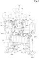
- the console 20 includes a support frame 36 attached to the machine body 2, and a cover member 37 to cover the support frame 36.
- the support frame 36 includes a first side plate 36A, a second side plate 36B, a coupling plate 36C, and fixed plates 36D.
- the first side plate 36A and the second side plate 36B are formed of plate members elongated in the up-down direction, and are arranged such that they face each other with a space therebetween in the machine-body width direction with their plate surfaces facing in the machine-body width direction.
- the coupling plate 36C is located between upper portions of the first side plate 36A and the second side plate 36B, and couples the upper portions of the first side plate 36A and the second side plate 36B to each other.
- the fixed plates 36D are fixed to a lower end of the first side plate 36A and a lower end of the second side plate 36B, and are fixed to the machine body 2 (step plate 26) by bolt(s) and/or the like.
- the cover member 37 includes two portions, that is, a front cover 37A and a rear cover 37B.
- the pair of traveling levers 22 are arranged in the machine-body width direction at a substantially central portion in the machine-body width direction of the console 20.
- the proximal portions of the traveling levers 22 are located in the cover member 37, and are supported by a traveling lever support 38 provided at a substantially central portion in the machine-body width direction of the coupling plate 36C (console 20) such that the traveling levers 22 are swingable in the front-rear direction K3.
- the upper portions of the pair of traveling levers 22 project upward from the cover member 37.
- a control valve unit 23 is provided inside the console 20.
- the control valve unit 23 is located below the coupling plate 36C such that the control valve unit 23 is located between the first side plate 36A and the second side plate 36B, and is attached to the first side plate 36A and the second side plate 36B. That is, the control valve unit 23 is attached to the support frame 36.
- the control valve unit 23 is an assembly of a plurality of control valves V1 to V10 to control hydraulic actuators provided in or on the working machine 1 (including hydraulic actuator(s) provided later). Specifically, the control valve unit 23 is a valve unit including the plurality of control valves V1 to V10 arranged in the machine-body width direction and connected to each other. Note that the control valve unit 23 may include a common valve body and a plurality of control valves incorporated in the common valve body.
- the control valves included in the control valve unit 23 are direct-acting spool direction switching valves to change the direction of hydraulic fluid to actuate hydraulic actuator(s).
- the control include a speed-change control valve V1, a turn control valve V2, an arm control valve V3, a first travel control valve V4, a dozer control valve V5, an auxiliary control valve V6, a second travel control valve V7, a swing control valve V8, a bucket control valve V9, and a boom control valve V10.
- the speed-change control valve V1 is operated by the speed-change pedal 33 to control, for example, a swash plate angle cylinder to change the tilt angle of the swash plate of the traveling motor 28.
- the turn control valve V2 controls the turning motor M1.
- the arm control valve V3 controls the arm cylinder 16.
- the first travel control valve V4 is operated by the left traveling lever 22 to control the traveling motor 28 of the left traveling device 3.
- the dozer control valve V5 is operated by the dozer lever 60 to control the dozer cylinder.
- the auxiliary control valve V6 is operated by the SP pedal 34 to control a hydraulic attachment.
- the second travel control valve V7 is operated by the right traveling lever 22 to control the traveling motor 28 of the right traveling device 3.
- the swing control valve V8 is operated by the swing pedal 32 to control the swing cylinder.
- the bucket control valve V9 controls the bucket cylinder 17.
- the boom control valve V10 controls the boom cylinder 15.
- the turn control valve V2, the arm control valve V3, the bucket control valve V9, and the boom control valve V10 are pilot-operated switching valves to be pilot-operated by the first manipulating lever 31L (first remote control valve 21L) and the second manipulating lever 31R (second remote control valve 21R).
- the speed-change control valve V1, the first travel control valve V4, the dozer control valve V5, the auxiliary control valve V6, the second travel control valve V7, and the swing control valve V8 are control valves (other control valves) to control the objects to be operated using operation members (speed-change pedal 33, traveling lever 22, dozer lever 60, SP pedal 34, swing pedal 32) attached to the console 20.
- control valves in the control valve unit 23 is an example, and is not limited to the example illustrated in the drawings.
- a first tube 39A and a second tube 39B which are flexible tubes are guided at a lower end of a left portion of the hood 8.
- the first tube 39A extends from a back surface of the first remote control valve 21L, and is guided to a lower end of a left portion of the console 20 through the inside of the machine body 2 (see FIG. 3 ).
- a plurality of pilot hoses connected to the first remote control valve 21L are bundled and inserted (housed) in the first tube 39A.
- the second tube 39B extends from a back surface of the second remote control valve 21R, and is guided to the lower end of the left portion of the console 20 through the inside of the machine body 2 (see FIG. 3 ).
- a plurality of pilot hoses connected to the second remote control valve 21R are bundled and inserted (housed) in the second tube 39B.
- the console 20 houses therein a pattern switch 41 to switch a pattern in which the manual operator 31 (first manipulating lever 31L, second manipulating lever 31R) is used to operate a plurality of hydraulic actuators (boom cylinder 15, arm cylinder 16, bucket cylinder 17, turning motor M1) (such a pattern is hereinafter referred to as "operation pattern") between a plurality of operation patterns.
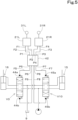
- the pattern switch 41 includes a pattern switching valve 42 to switch the operation pattern by changing the direction of the flow of pilot fluid caused by the manual operator 31 to pilot-operate the control valve.
- the pattern switching valve 42 is provided at an intermediate portion of a pilot circuit connecting the first remote control valve 21L and the second remote control valve 21R with the boom control valve V10 and the arm control valve V3.
- the first remote control valve 21L is connected to the pattern switching valve 42 by a first pilot fluid passage F1 and a second pilot fluid passage F2.
- the second remote control valve 21R is connected to the pattern switching valve 42 by a third pilot fluid passage F3 and a fourth pilot fluid passage F4.
- the arm control valve V3 includes a dump pressure receiver 44a and a crowd pressure receiver 44b, the dump pressure receiver 44a is connected to the pattern switching valve 42 via a fifth pilot fluid passage F5, and the crowd pressure receiver 44b is connected to the pattern switching valve 42 via a sixth pilot fluid passage F6.
- the boom control valve V10 includes a lowering pressure receiver 45a and a raising pressure receiver 45b, the lowering pressure receiver 45a is connected to the pattern switching valve 42 via a seventh pilot fluid passage F7, and the raising pressure receiver 45b is connected to the pattern switching valve 42 via an eighth pilot fluid passage F8.
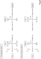
- the operation patterns to be switched by the pattern switch 41 include a first operation pattern and a second operation pattern illustrated in FIG. 6 .
- the arm 13 is caused to swing by pivoting the first manipulating lever 31L forward or rearward, and the machine body 2 is caused to turn by pivoting the first manipulating lever 31L leftward or rightward.
- the boom 12 is caused to swing by pivoting the second manipulating lever 31R forward or rearward, and the bucket 14 is caused to swing by pivoting the second manipulating lever 31R leftward or rightward.
- the boom 12 is caused to swing by pivoting the first manipulating lever 31L forward or rearward, and the machine body 2 is caused to turn by pivoting the first manipulating lever 31L leftward or rightward.
- the arm 13 is caused to swing by pivoting the second manipulating lever 31R forward or rearward, and the bucket 14 is caused to swing by pivoting the second manipulating lever 31R leftward or rightward.
- the arm 13 is operated by pivoting the first manipulating lever 31L forward or rearward, and the boom 12 is operated by pivoting the second manipulating lever 31R forward or rearward, whereas in the second operation pattern, the boom 12 is operated by pivoting the first manipulating lever 31L forward or rearward, and the arm 13 is operated by pivoting the second manipulating lever 31R forward or rearward.
- a pilot pressure acts on the dump pressure receiver 44a through the first pilot fluid passage F1, the pattern switching valve 42, and then the fifth pilot fluid passage F5, so that the arm cylinder 16 retracts and the arm 13 performs a dumping action.
- the pilot pressure acts on the crowd pressure receiver 44b through the second pilot fluid passage F2, the pattern switching valve 42, and then the sixth pilot fluid passage F6, so that the arm cylinder 16 extends and the arm 13 performs a crowding action.
- the pilot pressure acts on the lowering pressure receiver 45a through the third pilot fluid passage F3, the pattern switching valve 42, and then the seventh pilot fluid passage F7, so that the boom cylinder 15 extends and the boom is lowered.
- the pilot pressure acts on the raising pressure receiver 45b through the fourth pilot fluid passage F4, the pattern switching valve 42, and then the eighth pilot fluid passage F8, so that the boom cylinder 15 retracts and the boom 12 is raised.
- the pilot pressure acts on the lowering pressure receiver 45a through the first pilot fluid passage F1, the pattern switching valve 42, and then the seventh pilot fluid passage F7, so that the boom cylinder 15 extends and the boom 12 is lowered.
- the pilot pressure acts on the raising pressure receiver 45b through the second pilot fluid passage F2, the pattern switching valve 42, and then the eighth pilot fluid passage F8, so that the boom cylinder 15 retracts and the boom 12 is raised.
- the pilot pressure acts on the dump pressure receiver 44a through the third pilot fluid passage F3, the pattern switching valve 42, and then the fifth pilot fluid passage F5, so that the arm cylinder 16 retracts and the arm 13 performs a dumping action.
- the pilot pressure acts on the crowd pressure receiver 44b through the fourth pilot fluid passage F4, the pattern switching valve 42, and then the sixth pilot fluid passage F6, so that the arm cylinder 16 extends and the arm 13 performs a crowding action.
- the number of operation patterns to be switched by the pattern switch 41 may be three or more, and the control valves switched by the pattern switch 41 are not limited to the boom control valve V10 and the arm control valve V3.
- the pattern switch 41 is provided at an upper portion of the console 20.
- the pattern switch 41 since the pilot hoses guided from the first remote control valve 21L and the second remote control valve 21R to the console 20 are inserted through the lower end of the left portion of the console 20, the pattern switch 41 is provided at a left portion of the upper portion of the console 20 so that the pilot hoses can be easily guided.
- the pattern switch 41 may be provided at a right portion of the upper portion of the console 20.
- the pattern switch 41 is provided at an upper portion of the support frame 36 inside the cover member 37 such that the pattern switch 41 is located beside the traveling lever support 38 in the machine-body width direction.
- the console 20 includes therein a switch placement portion 46 for placement of the pattern switch 41, and the switch placement portion 46 is located, inside the cover member 37, at the upper portion of the support frame 36 such that the switch placement portion 46 is located beside the traveling lever support 38 in the machine-body width direction.
- the switch placement portion 46 is provided between the traveling lever support 38 and the first side plate 36A, on the coupling plate 36C.
- the switch placement portion 46 may be provided between the traveling lever support 38 and the second side plate 36B, on the coupling plate 36C.
- the pattern switch 41 includes a valve bracket 47 to which the pattern switching valve 42 is attached, the pattern switching valve 42, an operation mechanism 48 to operate the pattern switching valve 42, and a contact member 49.
- the operation mechanism 48 includes a pivot shaft 52, a swing arm 53, a switching lever 54, and an interlock mechanism 55.
- the swing arm 53 includes a support piece 53a, a switching lever support 53b, and an arm portion 53c.
- the support piece 53a is supported by the pivot shaft 52 such that it is rotatable about an axis of the pivot shaft 52.
- the support piece 53a has a rotational resistance applied thereto by a disk spring 57 fitted on the pivot shaft 52 and superposed on the support piece 53a and by a lock nut 58 screwed onto the pivot shaft 52 above the disk spring 57.
- the switching lever support 53b is provided at a lower end of an extension 53d extending downward from the support piece 53a.
- the switching lever support 53b is in a tubular shape (cylindrical shape).
- the arm portion 53c extends from the support piece 53a toward the first side plate 36A.
- the switching lever 54 is an operation member used to switch the operation pattern between the first operation pattern and the second operation pattern.
- the switching lever 54 includes a lever shaft 54A and a lever grip 54B.
- the lever shaft 54A includes a rod member (round rod member) and is inserted in the switching lever support 53b such that it is movable in an axial direction.
- the lever grip 54B is provided on a rear portion (proximal portion) of the lever shaft 54A.
- a stopper 59 is provided at a distal end portion of the lever shaft 54A. The stopper 59 comes into contact with the switching lever support 53b to prevent the lever shaft 54A from coming off the switching lever support 53b.
- the interlock mechanism 55 includes a first link 55A and a second link 55B.
- One end portion of the first link 55A is pivotally coupled to a left end portion of the arm portion 53c of the swing arm 53 via a first pivot 62A.
- One end portion of the second link 55B is fixed to an upper surface of the valve element 42b by bolt(s) 63.
- the opposite portion of the first link 55A and the opposite end portion of the second link 55B are pivotally coupled together via a second pivot 62B.
- the contact member 49 is located at an upper rear portion of a right side surface of the vertical wall 47b of the valve bracket 47.
- the contact member 49 includes a rod member (round rod member) and includes a first portion 49a and a second portion 49b.
- the first portion 49a is fixed to the right side surface of the vertical wall 47b and extends in the machine-body width direction (rightward from the vertical wall 47b).
- the second portion 49b extends upward from the right end of the first portion 49a.
- the second portion 49b and the vertical wall 47b define a space which allows passage of the lever shaft 54A of the switching lever 54.
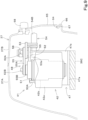
- the console 20 has, in the cover member 37, an opening 64 at a position corresponding to the pattern switch 41, and a lid member 65 to open and close the opening 64.
- the opening 64 and the lid member 65 are provided in an upper left portion of a back surface (the surface facing the operator's seat 5) of the cover member 37.
- a lower portion of the lid member 65 is supported by a support 66 such that the lid member 65 is rotatable about an axis of a support shaft 67 extending in the machine-body width direction.
- lid member 65 An upper portion of the lid member 65 is held in a closed state by a fixing member 68 that is screwed to the cover member 37 when in the closed state.
- a fixing member 68 that is screwed to the cover member 37 when in the closed state.
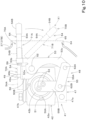
- the pattern switch 41 is configured such that, when the first operation pattern is selected, the switching lever 54 is in a first operation position 70A in which the switching lever 54 extends in the front-rear direction.
- the switching lever 54 In the first operation position 70A, the switching lever 54 is movable between an extended state (first extended state) 71A in which the switching lever 54 is extended rearward to a position in which the stopper 59 is in contact with the switching lever support 53b as indicated by solid lines in FIG. 10 , and a retracted state (first retracted state) 72A in which the switching lever 54 is retracted forward to a position in which the lever grip 54B is in contact with the switching lever support 53b as indicated by dot-dot-dash lines in FIG. 10 .
- the switching lever 54 projects through the opening 64 in the first extended state 71A.
- the switching lever 54 is housed inside the lid member 65 (in the cover member 37) in the first retracted state 72A.
- the switching lever 54 does not hinder the operator from getting on/off the working machine 1 or using operation members attached to the console 20.
- the switching lever 54 extends between the second portion 49b of the contact member 49 and the vertical wall 47b, and an end of the switching lever 54 is located forward of the contact member 49.
- the arm portion 53c extends leftward from the pivot shaft 52, the first link 55A is inclined rightward as the first link 55A extends forward, and the second link 55B projects leftward from the valve element 42b (extends in the machine-body width direction).
- the contact portion 51 is in contact with the first restrictor 50A from the right.
- the pattern switch 41 is configured such that, when the second operation pattern is selected, the switching lever 54 is in the second operation position 70B in which the switching lever 54 extends diagonally forward and rightward.
- the switching lever 54 In the second operation position 70B, the switching lever 54 is movable between an extended state (second extended state) 71B in which the switching lever 54 is pulled rearward to a position in which the stopper 59 is in contact with the switching lever support 53b as indicated by solid lines in FIG. 11 , and a retracted state (second retracted state) 72B in which the switching lever 54 is pushed forward to a position in which the lever grip 54B is in contact with the switching lever support 53b as indicated by dot-dot-dash lines in FIG. 11 .
- the switching lever 54 projects through the opening 64 in the second extended state 71B.
- the switching lever 54 is housed inside the lid member 65 (in the cover member 37) in the second retracted state 72B. With this, the switching lever 54 does not hinder the operator from getting on/off the working machine 1 or using operation members attached to the console 20.
- an end portion of the switching lever 54 is located rightward of the second portion 49b of the contact member 49.
- the switching between the first operation pattern and the second operation pattern is not performed at the point in time at which the switching lever 54 reached the first operation position 70A or the second operation position 70B, but is performed before the switching lever 54 reaches the first operation position 70A or the second operation position 70B. That is, when the switching lever 54 is pivoted from the first operation position 70A to the second operation position 70B, the first operation pattern is switched to the second operation pattern before the switching lever 54 reaches the second operation position 70B, and when the switching lever 54 is pivoted from the second operation position 70B to the first operation position 70A, the second operation pattern is switched to the first operation pattern before the switching lever 54 reaches the first operation position 70A.
- the switching lever 54 when the switching lever 54 is in the first operation position 70A or the second operation position 70B, the switching lever 54 does not come into contact with the contact member 49 (second portion 49b) even when the switching lever 54 enters the retracted state (first retracted state 72A, second retracted state 72B).
- the switching lever 54 when the switching lever 54 is within a pivoting range 73 between the first operation position 70A and the second operation position 70B (on the same side of the first operation position 70A as the second operation position 70B, and on the same side of the second operation position 70B as the first operation position 70A) and is moved in a direction 74 from the extended state to the retracted state, the switching lever 54 comes into contact with the contact member 49 (second portion 49b) such that the switching lever 54 projects through the opening 64 to stop the switching lever 54 from moving.
- the switching lever 54 when the switching lever 54 is located at a position between the first operation position 70A and the second operation position 70B, the switching lever 54 is not brought into the retracted state, and the lid member 65 cannot be closed. That is, while the operation patterns are being switched, the switching lever 54 cannot be housed in the cover member 37, and the lid member 65 cannot be closed. Thus, it is possible to allow the operator to recognize that the operation patterns are being switched.
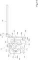
- FIGS. 14 and 15 illustrate another embodiment of the pattern switch 41.
- the pattern switch 41 according to another embodiment is substantially the same as the pattern switch 41 according to the above-described embodiment, except that the switching lever 54 is attachable and detachable to and from the switching lever support 53b.
- the switching lever support 53b is in a rectangular block shape, and includes a screw hole 75 (a hole having an internal thread in an inner peripheral surface).
- the switching lever 54 includes an external thread portion 76 (a portion having an external thread in an outer peripheral surface) at an end portion thereof.
- the switching lever 54 can be attached to the switching lever support 53b by screwing the external thread portion 76 into the screw hole 75.
- the switching lever 54 projects through the opening 64.
- the switching lever 54 By rotating the switching lever 54 to unthread the threaded portions, the switching lever 54 can be removed from the switching lever support 53b, so that the opening 64 can be closed by the lid member 65.
- a holder to hold the switching lever 54 is provided at the cover member 37 or the like.
- a working machine 1 is a working machine 1 provided with a plurality of hydraulic actuators (turning motor M1, boom cylinder 15, arm cylinder 16, bucket cylinder 17), the working machine 1 including a machine body 2, an operator's seat 5 on the machine body 2, a console 20 extending upward from the machine body 2 in front of the operator's seat 5, a manual operator 31 to operate the plurality of hydraulic actuators, and a pattern switch 41 to switch an operation pattern in which the manual operator 31 is used to operate the plurality of hydraulic actuators between a plurality of operation patterns, wherein the console 20 includes therein a switch placement portion 46 for placement of the pattern switch 41.
- a plurality of hydraulic actuators turning motor M1, boom cylinder 15, arm cylinder 16, bucket cylinder 17
- the working machine 1 including a machine body 2, an operator's seat 5 on the machine body 2, a console 20 extending upward from the machine body 2 in front of the operator's seat 5, a manual operator 31 to operate the plurality of hydraulic actuators, and a pattern switch 41 to switch an operation pattern in which the
- the working machine 1 further includes a traveling device 3 to support the machine body 2 such that the machine body 2 is allowed to travel, and a traveling lever 22 to operate the traveling device 3, the traveling lever 22 being provided at a substantially central portion in a machine-body width direction of an upper portion of the console 20.
- the console 20 includes a support frame 36 attached to the machine body 2, a cover member 37 to cover the support frame 36, and a traveling lever support 38 provided at an upper portion of the support frame 36 to support the traveling lever 22.
- the switch placement portion 46 is located, inside the cover member 37, at the upper portion of the support frame 36 such that the switch placement portion 46 is located beside the traveling lever support 38 in the machine-body width direction.
- the working machine 1 further includes a control valve unit 23 including a plurality of control valves (turn control valve V2, arm control valve V3, bucket control valve V9, boom control valve V10) to control the plurality of hydraulic actuators.
- the support frame 36 includes a first side plate 36A and a second side plate 36B facing each other with a space therebetween in the machine-body width direction, and a coupling plate 36C to connect upper portions of the first side plate 36A and the second side plate 36B.
- the control valve unit 23 is located below the coupling plate 36C such that the control valve unit 23 is located between the first side plate 36A and the second side plate 36B.
- the traveling lever support 38 is provided at a substantially central portion in the machine-body width direction of the coupling plate 36C.
- the switch placement portion 46 is provided between the traveling lever support 38 and the first side plate 36A or the second side plate 36B on the coupling plate 36C.
- the console 20 includes, in the cover member 37, an opening 64 at a position corresponding to the pattern switch 41, and a lid member 65 to open and close the opening 64.
- the plurality of operation patterns include a first operation pattern and a second operation pattern that differs from the first operation pattern.
- the pattern switch 41 includes a switching lever 54 pivotable between a first operation position 70A in which the first operation pattern is selected and a second operation position 70B in which the second operation pattern is selected.
- the switching lever 54 is, in each of the first and second operation positions 70A and 70B, movable between an extended state (first extended state 71A, second extended state 71B) in which the switching lever 54 projects through the opening 64 and a retracted state (first retracted state 72A, second retracted state 72B) in which the switching lever 54 is retracted within the lid member 65.
- a working machine 1 is a working machine 1 provided with a plurality of hydraulic actuators (turning motor M1, boom cylinder 15, arm cylinder 16, bucket cylinder 17), the working machine 1 including a machine body 2, a cover member 37 on the machine body 2, a manual operator 31 to operate the plurality of hydraulic actuators, and a pattern switch 41 to switch an operation pattern in which the manual operator 31 is used to operate the plurality of hydraulic actuators between a plurality of operation patterns, the pattern switch 41 being housed inside the cover member 37, the cover member 37 includes an opening 64 at a position corresponding to the pattern switch 41, and a lid member 65 to open and close the opening 64, the plurality of operation patterns include a first operation pattern and a second operation pattern, the pattern switch 41 includes a switching lever 54 pivotable between a first operation position 70A in which the first operation pattern is selected and a second operation position 70B in which the second operation pattern is selected, and the switching lever 54 is, in each of the first and second operation positions 70A and 70B, movable between an extended state (first extended
- the working machine 1 further includes a contact member 49 to, when the switching lever 54 is within a pivoting range 73 between the first operation position 70A and the second operation position 70B and is moved in a direction 74 from the extended state toward the retracted state, come into contact with the switching lever 54 such that the switching lever 54 projects through the opening 64 to stop the switching lever 54 from moving.
- the working machine 1 further includes a plurality of control valves to be pilot-operated by the manual operator 31, the plurality of control valves being provided such that the plurality of control valves correspond to the plurality of hydraulic actuators to control the plurality of hydraulic actuators.
- the pattern switch 41 includes a pattern switching valve 42 to switch between the plurality of operation patterns by changing a direction of a flow of pilot fluid to pilot-operate the control valves by operation of the manual operator 31, a pivot shaft 52 about which the switching lever 54 is to be pivoted, a swing arm 53 supported such that the swing arm 53 is pivotable about the pivot shaft 52 and including a switching lever support 53b to support the switching lever 54 such that the switching lever 54 is movable between the extended state and the retracted state, and an interlock mechanism 55 to interlock the swing arm 53 and a valve element 42b of the pattern switching valve 42.
Landscapes
- Engineering & Computer Science (AREA)
- Mining & Mineral Resources (AREA)
- Civil Engineering (AREA)
- General Engineering & Computer Science (AREA)
- Structural Engineering (AREA)
- Mechanical Engineering (AREA)
- Operation Control Of Excavators (AREA)
Abstract
Description
- The present invention relates to a working machine.
- A working machine disclosed in Patent Literature 1 (PTL 1) is known.
- The working machine disclosed in
PTL 1 is provided with a plurality of hydraulic actuators. A manual operator that operates the plurality of hydraulic actuators is provided beside an operator's seat mounted on a machine body. Furthermore, a pattern switch that switches an operation pattern of the manual operator for the plurality of hydraulic actuators between a plurality of operation patterns is provided on the machine body. The pattern switch is provided below the operator's seat. - PTL 1:
Japanese Unexamined Patent Application Publication No. 2014-32462 - Compact working machines have an issue in that it is difficult to place the pattern switch below the operator's seat in terms of space.
- In view of the above-described issue, an object of the present invention is to provide a working machine which has space for placement of a pattern switch even if the working machine is compact.
- A working machine according to an aspect of the present invention is a working machine provided with a plurality of hydraulic actuators, the working machine including a machine body, an operator's seat on the machine body, a console extending upward from the machine body in front of the operator's seat; a manual operator to operate the plurality of hydraulic actuators, and a pattern switch to switch an operation pattern in which the manual operator is used to operate the plurality of hydraulic actuators between a plurality of operation patterns, wherein the console includes therein a switch placement portion for placement of the pattern switch.
- The working machine may further include a traveling device to support the machine body such that the machine body is allowed to travel, and a traveling lever to operate the traveling device, the traveling lever being provided at a substantially central portion in a machine-body width direction of an upper portion of the console. The console may include a support frame attached to the machine body, a cover member to cover the support frame, and a traveling lever support provided at an upper portion of the support frame to support the traveling lever. The switch placement portion may be located, inside the cover member, at the upper portion of the support frame such that the switch placement portion is located beside the traveling lever support in the machine-body width direction.
- The working machine may further include a control valve unit including a plurality of control valves to control the plurality of hydraulic actuators. The support frame may include a first side plate and a second side plate facing each other with a space therebetween in the machine-body width direction, and a coupling plate to connect upper portions of the first side plate and the second side plate. The control valve unit may be located below the coupling plate such that the control valve unit is located between the first side plate and the second side plate. The traveling lever support may be provided at a substantially central portion in the machine-body width direction of the coupling plate. The switch placement portion may be provided between the traveling lever support and the first side plate or the second side plate on the coupling plate.
- The console may include, in the cover member, an opening at a position corresponding to the pattern switch, and a lid member to open and close the opening. The plurality of operation patterns may include a first operation pattern and a second operation pattern that differs from the first operation pattern. The pattern switch may include a switching lever pivotable between a first operation position in which the first operation pattern is selected and a second operation position in which the second operation pattern is selected. The switching lever may be, in each of the first and second operation positions, movable between an extended state in which the switching lever projects through the opening and a retracted state in which the switching lever is retracted within the lid member.
- A working machine according to an aspect of the present invention is a working machine provided with a plurality of hydraulic actuators, the working machine including a machine body, a cover member on the machine body, a manual operator to operate the plurality of hydraulic actuators, and a pattern switch to switch an operation pattern in which the manual operator is used to operate the plurality of hydraulic actuators between a plurality of operation patterns, the pattern switch being housed inside the cover member, wherein the cover member includes an opening at a position corresponding to the pattern switch, and a lid member to open and close the opening, the plurality of operation patterns include a first operation pattern and a second operation pattern, the pattern switch includes a switching lever pivotable between a first operation position in which the first operation pattern is selected and a second operation position in which the second operation pattern is selected, and the switching lever is, in each of the first and second operation positions, movable between an extended state in which the switching lever projects through the opening and a retracted state in which the switching lever is retracted within the lid member.
- The working machine may further include a contact member to, when the switching lever is within a pivoting range between the first operation position and the second operation position and is moved in a direction from the extended state toward the retracted state, come into contact with the switching lever such that the switching lever projects through the opening to stop the switching lever from moving.
- The working machine may further include a plurality of control valves to be pilot-operated by the manual operator, the plurality of control valves being provided such that the plurality of control valves correspond to the plurality of hydraulic actuators to control the plurality of hydraulic actuators. The pattern switch may include a pattern switching valve to switch between the plurality of operation patterns by changing a direction of a flow of pilot fluid to pilot-operate the control valves by operation of the manual operator, a pivot shaft about which the switching lever is to be pivoted, a swing arm supported such that the swing arm is pivotable about the pivot shaft and including a switching lever support to support the switching lever such that the switching lever is movable between the extended state and the retracted state, and an interlock mechanism to interlock the swing arm and a valve element of the pattern switching valve.
- With the above-described working machine, it is possible to save space for placement of a pattern switch even if the working machine is compact.
-
- [
FIG. 1] FIG. 1 is a side view of a working machine. - [
FIG. 2] FIG. 2 is a perspective view of an operator's seat and the vicinity of the operator's seat. - [
FIG. 3] FIG. 3 is a perspective view of a console. - [
FIG. 4] FIG. 4 is a perspective view of the inside of the console. - [
FIG. 5] FIG. 5 is a fluid circuit diagram. - [
FIG. 6] FIG. 6 illustrates examples of operation patterns. - [
FIG. 7] FIG. 7 is a perspective view of a pattern switch as viewed from the front. - [
FIG. 8] FIG. 8 is a perspective view of the pattern switch as viewed from the rear. - [
FIG. 9] FIG. 9 is a side sectional view of the portion where the pattern switch is provided. - [
FIG. 10] FIG. 10 is a plan view of the pattern switch when a first operation pattern is elected. - [
FIG. 11] FIG. 11 is a plan view of the pattern switch when a second operation pattern is selected. - [
FIG. 12] FIG. 12 is a perspective view of the console with a lid member open. - [
FIG. 13] FIG. 13 is a plan view illustrating positions of a switching lever. - [
FIG. 14] FIG. 14 is a plan view of a pattern switch according to another embodiment. - [
FIG. 15] FIG. 15 is a perspective view of the pattern switch according to another embodiment. - The following description discusses embodiments of the present invention with reference to the drawings as appropriate.
-
FIG. 1 is a schematic side view of aworking machine 1 according to the present embodiment. In the present embodiment, a compact backhoe, which is a swivel working machine, is illustrated as an example of theworking machine 1. - As illustrated in
FIG. 1 , theworking machine 1 includes atravel unit 1A and aworking device 4 provided on thetravel unit 1A. Thetravel unit 1A includes atraveling device 3 and a machine body (swivel base) 2 on thetraveling device 3. An operator'sseat 5 on which an operator is seated is provided on themachine body 2. - In the present embodiment, the front (direction of arrow K1 in
FIG. 1 ) of the operator seated on the operator'sseat 5 is described as forward, the rear (direction of arrow K2 inFIG. 1 ) of the operator is described as rearward, the left (near side inFIG. 1 ) of the operator is described as leftward, and the right (far side inFIG. 1 ) of the operator is described as rightward. Also, the direction along arrow K3 inFIG. 1 is described as a front-rear direction (machine-body front-rear direction), and a horizontal direction perpendicular to the front-rear direction K3 is described as a machine-body width direction (width direction of the machine body 2). A direction from a central portion to a right portion or to a left portion along the width direction of themachine body 2 is described as a machine-body outward side (an outward side in the machine-body width direction). That is, the machine-body outward direction is one of the machine-body width directions and is a direction away from the widthwise center of themachine body 2. A direction opposite to the machine-body outward direction is described as a machine-body inward direction (inward direction along the machine-body width direction). That is, the machine-body inward direction is one of the machine-body width directions and is a direction toward the widthwise center of themachine body 2. - As illustrated in
FIG. 1 , themachine body 2 is supported by thetraveling device 3 such that themachine body 2 is rotatable about a vertical axis (an axis extending in an up-down direction). Themachine body 2 includes aswivel base plate 6 that defines a bottom portion of themachine body 2, and aweight 7 attached to a rear portion of theswivel base plate 6. Theswivel base plate 6 is supported on a frame of thetraveling device 3 via a bearingbody 19 such that theswivel base plate 6 is rotatable about the vertical axis, and rotates leftward or rightward by being driven by a turning motor M1 including a hydraulic motor (hydraulic actuator). Astep plate 26 on which the operator seated on the operator'sseat 5 places their foot is located above theswivel base plate 6. The space between theswivel base plate 6 and thestep plate 26 is covered with aside cover 27. The workingdevice 4 is attached to a front portion of themachine body 2. Theweight 7 is a counterweight to balance the weight with the workingdevice 4. AROPS 24 to protect the operator seated on the operator'sseat 5 is provided above themachine body 2. - A
hood 8 is located above a rear portion of themachine body 2. The operator'sseat 5 is located above thehood 8. As indicated by dot-dot-dash lines inFIG. 1 , thehood 8 can open by rotating rearward. Thehood 8 houses therein aprime mover 10 as a drive source, ahydraulic fluid tank 9 which stores a hydraulic fluid to drive hydraulic actuators such as hydraulic cylinder(s), hydraulic motor(s), and/or the like provided in the workingmachine 1, a hydraulic pump (not illustrated) to suck and deliver the hydraulic fluid from thehydraulic fluid tank 9, and the like. Note that a diesel engine is used as theprime mover 10 in the present embodiment, however theprime mover 10 is not limited to the diesel engine. For example, theprime mover 10 may be another internal combustion engine such as a gasoline engine, or may include an electric motor and/or the like. - As illustrated in
FIG. 1 , the travelingdevice 3 is a crawler traveling device and is provided below each of right and left portions of themachine body 2.Such traveling devices 3 are driven by travelingmotors 28 including hydraulic motors. Adozer 11 is provided at front portions of the travelingdevices 3. Thedozer 11 is driven by a dozer cylinder (not illustrated). - As illustrated in
FIG. 1 , the workingdevice 4 includes aboom 12, anarm 13, and abucket 14 as a working tool. The workingdevice 4 further includes, as mechanisms to drive the boom and the like, aboom cylinder 15, anarm cylinder 16, and abucket cylinder 17 as a working tool cylinder. Theboom cylinder 15, thearm cylinder 16, thebucket cylinder 17, and the dozer cylinder include hydraulic cylinders (hydraulic actuators). These hydraulic cylinders are driven by hydraulic fluid supplied from thehydraulic fluid tank 9 via the hydraulic pump. The workingdevice 4 is operated using a manipulating lever 31 (described later). - A proximal end portion of the
boom 12 is pivotally supported by aswing bracket 18 provided at the front portion of themachine body 2 such that theboom 12 is swingable about a horizontal axis. Theswing bracket 18 is pivotally supported by asupport bracket 29 provided at themachine body 2 such that theswing bracket 18 is swingable about a vertical axis. A swing cylinder (not illustrated) including a hydraulic cylinder is attached to themachine body 2, and theswing bracket 18 swings by being driven by the swing cylinder. A proximal end portion of thearm 13 is pivotally supported by a distal end portion of theboom 12 such that thearm 13 is swingable about a horizontal axis. Thebucket 14 is attached to a distal end portion of thearm 13. - The
boom cylinder 15 couples theswing bracket 18 and a middle portion of theboom 12. Theboom 12 swings upward/downward by extension/retraction of theboom cylinder 15. In the present embodiment, theboom 12 swings in a boom raising direction D1 by the retraction of theboom cylinder 15, and theboom 12 swings in a boom lowering direction D2 by the extension of theboom cylinder 15. - The
arm cylinder 16 couples the middle portion of theboom 12 and the proximal end portion of thearm 13. Thearm 13 swings upward/downward by extension/retraction of thearm cylinder 16. In the present embodiment, thearm 13 swings in an arm raising direction (arm dump direction) D3 by the retraction of thearm cylinder 16, and swings in an arm lowering direction (arm crowd direction) D4 by the extension of thearm cylinder 16. - The
bucket cylinder 17 couples the proximal end portion of thearm 13 and an attachment of thebucket 14. Thebucket 14 performs shoveling/dumping by extension/retraction of thebucket cylinder 17. In the present embodiment, thebucket 14 swings in a dump direction (bucket dump direction) D5 by the retraction of thebucket cylinder 17, and thebucket 14 swings in a shovel direction (bucket crowd direction) D6 by the extension of thebucket cylinder 17. - As illustrated in
FIG. 2 , manipulator bases 30 are provided on the left and right sides of the operator'sseat 5. Themanipulator base 30 located leftward of the operator'sseat 5 is referred to as afirst manipulator base 30L, and themanipulator base 30 located rightward of the operator'sseat 5 is referred to as asecond manipulator base 30R. - The
first manipulator base 30L has attached thereto a manual operator 31 (first manipulatinglever 31L) to operate a plurality of hydraulic actuators, a remote control valve 21 (firstremote control valve 21L) that is a pilot valve operated by the first manipulatinglever 31L, and afirst operating lever 43L to swing thefirst manipulator base 30L in the up-down direction. - The first manipulating
lever 31L can be used to operate two objects provided in the workingmachine 1. Specifically, the first manipulatinglever 31L can be pivoted forward, rearward, leftward, and rightward, and is used to operate one object by the forward/rearward pivot and operate another object by the leftward/rightward pivot. The first manipulatinglever 31L is operable to, by operating the firstremote control valve 21L, pilot-operate a control valve (pilot-operated switching valve) to control the corresponding object. Specifically, by pivoting the first manipulatinglever 31L forward/rearward or rightward/leftward, a pilot fluid corresponding to the pivot amount (degree of pivot of the lever) is output from the firstremote control valve 21L to the control valve to control the corresponding object. - The
second manipulator base 30R has attached thereto a manual operator 31 (second manipulatinglever 31R) to operate a plurality of hydraulic actuators, a remote control valve 21 (secondremote control valve 21R) that is a pilot valve operated by the second manipulatinglever 31R, and asecond operating lever 43R to swing thesecond manipulator base 30R in the up-down direction. - The second manipulating
lever 31R also can be used to operate two objects provided in the workingmachine 1. Specifically, the second manipulatinglever 31R also can be pivoted forward, rearward, leftward, and rightward, and is used to operate one object by the forward/rearward pivot and operate another object by the leftward/rightward pivot. The second manipulatinglever 31R is operable to, by operating the secondremote control valve 21R, pilot-operate a control valve (pilot-operated switching valve) to control the corresponding object. Specifically, by pivoting the second manipulatinglever 31R forward/rearward or rightward/leftward, a pilot fluid corresponding to the pivot amount is output from the secondremote control valve 21R to the control valve that controls the corresponding object. - The objects to be operated by the first manipulating
lever 31L and the second manipulatinglever 31R are, for example, the turning motor M1 (machine body 2), the boom cylinder 15 (boom 12), the arm cylinder 16 (arm 13), and the bucket cylinder 17 (bucket 14). That is, themanual operator 31 can be used to rotate themachine body 2, swing theboom 12, swing thearm 13, and swing thebucket 14. - As illustrated in
FIG. 1 , aconsole 20 is provided at a front portion of thestep plate 26. Theconsole 20 extends upward from themachine body 2 in front of the operator'sseat 5 and thehood 8. Various operation members (operators) are attached to theconsole 20. - As illustrated in
FIG. 3 , the various operation members include a pair of travelinglevers 22, adozer lever 60, anaccelerator lever 61, aswing pedal 32, a speed-change pedal 33, anSP pedal 34, and/or the like. The pair of travelinglevers 22 are used to operate the traveling devices 3 (traveling motors 28). Thedozer lever 60 is used to operate the dozer 11 (dozer cylinder). Theaccelerator lever 61 is used to control rotation of theprime mover 10. Theswing pedal 32 is used to operate the swing bracket 18 (swing cylinder). The speed-change pedal 33 is used to change the speed stage of the travelingdevices 3 between a first speed stage and a second speed stage higher than the first speed. TheSP pedal 34 is a pedal used to operate another working tool (hydraulic attachment) which is attached instead of or in addition to thebucket 14 and which can be driven by a hydraulic actuator. - As illustrated in
FIG. 4 , theconsole 20 includes asupport frame 36 attached to themachine body 2, and acover member 37 to cover thesupport frame 36. - The
support frame 36 includes afirst side plate 36A, asecond side plate 36B, acoupling plate 36C, and fixedplates 36D. Thefirst side plate 36A and thesecond side plate 36B are formed of plate members elongated in the up-down direction, and are arranged such that they face each other with a space therebetween in the machine-body width direction with their plate surfaces facing in the machine-body width direction. Thecoupling plate 36C is located between upper portions of thefirst side plate 36A and thesecond side plate 36B, and couples the upper portions of thefirst side plate 36A and thesecond side plate 36B to each other. The fixedplates 36D are fixed to a lower end of thefirst side plate 36A and a lower end of thesecond side plate 36B, and are fixed to the machine body 2 (step plate 26) by bolt(s) and/or the like. - As illustrated in
FIG. 3 , thecover member 37 includes two portions, that is, afront cover 37A and arear cover 37B. - As illustrated in
FIG. 4 , the pair of travelinglevers 22 are arranged in the machine-body width direction at a substantially central portion in the machine-body width direction of theconsole 20. The proximal portions of the travelinglevers 22 are located in thecover member 37, and are supported by a travelinglever support 38 provided at a substantially central portion in the machine-body width direction of thecoupling plate 36C (console 20) such that the travelinglevers 22 are swingable in the front-rear direction K3. The upper portions of the pair of travelinglevers 22 project upward from thecover member 37. - A
control valve unit 23 is provided inside theconsole 20. Thecontrol valve unit 23 is located below thecoupling plate 36C such that thecontrol valve unit 23 is located between thefirst side plate 36A and thesecond side plate 36B, and is attached to thefirst side plate 36A and thesecond side plate 36B. That is, thecontrol valve unit 23 is attached to thesupport frame 36. - The
control valve unit 23 is an assembly of a plurality of control valves V1 to V10 to control hydraulic actuators provided in or on the working machine 1 (including hydraulic actuator(s) provided later). Specifically, thecontrol valve unit 23 is a valve unit including the plurality of control valves V1 to V10 arranged in the machine-body width direction and connected to each other. Note that thecontrol valve unit 23 may include a common valve body and a plurality of control valves incorporated in the common valve body. - The control valves included in the
control valve unit 23 are direct-acting spool direction switching valves to change the direction of hydraulic fluid to actuate hydraulic actuator(s). Specifically, the control include a speed-change control valve V1, a turn control valve V2, an arm control valve V3, a first travel control valve V4, a dozer control valve V5, an auxiliary control valve V6, a second travel control valve V7, a swing control valve V8, a bucket control valve V9, and a boom control valve V10. - The speed-change control valve V1 is operated by the speed-
change pedal 33 to control, for example, a swash plate angle cylinder to change the tilt angle of the swash plate of the travelingmotor 28. The turn control valve V2 controls the turning motor M1. The arm control valve V3 controls thearm cylinder 16. The first travel control valve V4 is operated by theleft traveling lever 22 to control the travelingmotor 28 of theleft traveling device 3. The dozer control valve V5 is operated by thedozer lever 60 to control the dozer cylinder. The auxiliary control valve V6 is operated by theSP pedal 34 to control a hydraulic attachment. The second travel control valve V7 is operated by theright traveling lever 22 to control the travelingmotor 28 of theright traveling device 3. The swing control valve V8 is operated by theswing pedal 32 to control the swing cylinder. The bucket control valve V9 controls thebucket cylinder 17. The boom control valve V10 controls theboom cylinder 15. - The turn control valve V2, the arm control valve V3, the bucket control valve V9, and the boom control valve V10 are pilot-operated switching valves to be pilot-operated by the first manipulating
lever 31L (firstremote control valve 21L) and the second manipulatinglever 31R (secondremote control valve 21R). - The speed-change control valve V1, the first travel control valve V4, the dozer control valve V5, the auxiliary control valve V6, the second travel control valve V7, and the swing control valve V8 are control valves (other control valves) to control the objects to be operated using operation members (speed-
change pedal 33, travelinglever 22,dozer lever 60,SP pedal 34, swing pedal 32) attached to theconsole 20. - Note that the arrangement of the control valves in the
control valve unit 23 is an example, and is not limited to the example illustrated in the drawings. - As illustrated in
FIG. 2 , afirst tube 39A and asecond tube 39B which are flexible tubes are guided at a lower end of a left portion of thehood 8. Thefirst tube 39A extends from a back surface of the firstremote control valve 21L, and is guided to a lower end of a left portion of theconsole 20 through the inside of the machine body 2 (seeFIG. 3 ). A plurality of pilot hoses connected to the firstremote control valve 21L are bundled and inserted (housed) in thefirst tube 39A. Thesecond tube 39B extends from a back surface of the secondremote control valve 21R, and is guided to the lower end of the left portion of theconsole 20 through the inside of the machine body 2 (seeFIG. 3 ). A plurality of pilot hoses connected to the secondremote control valve 21R are bundled and inserted (housed) in thesecond tube 39B. - As illustrated in
FIGS. 3 and4 , theconsole 20 houses therein apattern switch 41 to switch a pattern in which the manual operator 31 (first manipulatinglever 31L, second manipulatinglever 31R) is used to operate a plurality of hydraulic actuators (boom cylinder 15,arm cylinder 16,bucket cylinder 17, turning motor M1) (such a pattern is hereinafter referred to as "operation pattern") between a plurality of operation patterns. The pattern switch 41 includes apattern switching valve 42 to switch the operation pattern by changing the direction of the flow of pilot fluid caused by themanual operator 31 to pilot-operate the control valve. - As illustrated in
FIG. 5 , in the present embodiment, thepattern switching valve 42 is provided at an intermediate portion of a pilot circuit connecting the firstremote control valve 21L and the secondremote control valve 21R with the boom control valve V10 and the arm control valve V3. Specifically, the firstremote control valve 21L is connected to thepattern switching valve 42 by a first pilot fluid passage F1 and a second pilot fluid passage F2. The secondremote control valve 21R is connected to thepattern switching valve 42 by a third pilot fluid passage F3 and a fourth pilot fluid passage F4. The arm control valve V3 includes adump pressure receiver 44a and acrowd pressure receiver 44b, thedump pressure receiver 44a is connected to thepattern switching valve 42 via a fifth pilot fluid passage F5, and thecrowd pressure receiver 44b is connected to thepattern switching valve 42 via a sixth pilot fluid passage F6. The boom control valve V10 includes a loweringpressure receiver 45a and a raisingpressure receiver 45b, the loweringpressure receiver 45a is connected to thepattern switching valve 42 via a seventh pilot fluid passage F7, and the raisingpressure receiver 45b is connected to thepattern switching valve 42 via an eighth pilot fluid passage F8. - In the present embodiment, the operation patterns to be switched by the
pattern switch 41 include a first operation pattern and a second operation pattern illustrated inFIG. 6 . - As illustrated in
FIG. 6 , in the first operation pattern, thearm 13 is caused to swing by pivoting the first manipulatinglever 31L forward or rearward, and themachine body 2 is caused to turn by pivoting the first manipulatinglever 31L leftward or rightward. Theboom 12 is caused to swing by pivoting the second manipulatinglever 31R forward or rearward, and thebucket 14 is caused to swing by pivoting the second manipulatinglever 31R leftward or rightward. - In the second operation pattern, the
boom 12 is caused to swing by pivoting the first manipulatinglever 31L forward or rearward, and themachine body 2 is caused to turn by pivoting the first manipulatinglever 31L leftward or rightward. Thearm 13 is caused to swing by pivoting the second manipulatinglever 31R forward or rearward, and thebucket 14 is caused to swing by pivoting the second manipulatinglever 31R leftward or rightward. - As described above, in the present embodiment, in the first operation pattern, the
arm 13 is operated by pivoting the first manipulatinglever 31L forward or rearward, and theboom 12 is operated by pivoting the second manipulatinglever 31R forward or rearward, whereas in the second operation pattern, theboom 12 is operated by pivoting the first manipulatinglever 31L forward or rearward, and thearm 13 is operated by pivoting the second manipulatinglever 31R forward or rearward. - Specifically, in the first operation pattern, when the first manipulating
lever 31L is pivoted forward, a pilot pressure acts on thedump pressure receiver 44a through the first pilot fluid passage F1, thepattern switching valve 42, and then the fifth pilot fluid passage F5, so that thearm cylinder 16 retracts and thearm 13 performs a dumping action. When the first manipulatinglever 31L is pivoted rearward, the pilot pressure acts on thecrowd pressure receiver 44b through the second pilot fluid passage F2, thepattern switching valve 42, and then the sixth pilot fluid passage F6, so that thearm cylinder 16 extends and thearm 13 performs a crowding action. When the second manipulatinglever 31R is pivoted forward, the pilot pressure acts on the loweringpressure receiver 45a through the third pilot fluid passage F3, thepattern switching valve 42, and then the seventh pilot fluid passage F7, so that theboom cylinder 15 extends and the boom is lowered. When the second manipulatinglever 31R is pivoted rearward, the pilot pressure acts on the raisingpressure receiver 45b through the fourth pilot fluid passage F4, thepattern switching valve 42, and then the eighth pilot fluid passage F8, so that theboom cylinder 15 retracts and theboom 12 is raised. - In the second operation pattern, when the first manipulating
lever 31L is pivoted forward, the pilot pressure acts on the loweringpressure receiver 45a through the first pilot fluid passage F1, thepattern switching valve 42, and then the seventh pilot fluid passage F7, so that theboom cylinder 15 extends and theboom 12 is lowered. When the first manipulatinglever 31L is pivoted rearward, the pilot pressure acts on the raisingpressure receiver 45b through the second pilot fluid passage F2, thepattern switching valve 42, and then the eighth pilot fluid passage F8, so that theboom cylinder 15 retracts and theboom 12 is raised. When the second manipulatinglever 31R is pivoted forward, the pilot pressure acts on thedump pressure receiver 44a through the third pilot fluid passage F3, thepattern switching valve 42, and then the fifth pilot fluid passage F5, so that thearm cylinder 16 retracts and thearm 13 performs a dumping action. When the second manipulatinglever 31R is pivoted rearward, the pilot pressure acts on thecrowd pressure receiver 44b through the fourth pilot fluid passage F4, thepattern switching valve 42, and then the sixth pilot fluid passage F6, so that thearm cylinder 16 extends and thearm 13 performs a crowding action. - Note that the number of operation patterns to be switched by the
pattern switch 41 may be three or more, and the control valves switched by thepattern switch 41 are not limited to the boom control valve V10 and the arm control valve V3. - As illustrated in
FIGS. 3 and4 , thepattern switch 41 is provided at an upper portion of theconsole 20. In the present embodiment, since the pilot hoses guided from the firstremote control valve 21L and the secondremote control valve 21R to theconsole 20 are inserted through the lower end of the left portion of theconsole 20, thepattern switch 41 is provided at a left portion of the upper portion of theconsole 20 so that the pilot hoses can be easily guided. However, thepattern switch 41 may be provided at a right portion of the upper portion of theconsole 20. - As illustrated in
FIG. 4 , thepattern switch 41 is provided at an upper portion of thesupport frame 36 inside thecover member 37 such that thepattern switch 41 is located beside the travelinglever support 38 in the machine-body width direction. In other words, theconsole 20 includes therein aswitch placement portion 46 for placement of thepattern switch 41, and theswitch placement portion 46 is located, inside thecover member 37, at the upper portion of thesupport frame 36 such that theswitch placement portion 46 is located beside the travelinglever support 38 in the machine-body width direction. Specifically, theswitch placement portion 46 is provided between the travelinglever support 38 and thefirst side plate 36A, on thecoupling plate 36C. Theswitch placement portion 46 may be provided between the travelinglever support 38 and thesecond side plate 36B, on thecoupling plate 36C. - As illustrated in
FIGS. 7 and8 , thepattern switch 41 includes avalve bracket 47 to which thepattern switching valve 42 is attached, thepattern switching valve 42, anoperation mechanism 48 to operate thepattern switching valve 42, and acontact member 49. - The
valve bracket 47 includes anattachment wall 47a located on thecoupling plate 36C and attached to thecoupling plate 36C by bolt(s) and/or the like, and avertical wall 47b extending upward from a right edge (one of the edges closer to the traveling lever support 38) of theattachment wall 47a. - As illustrated in
FIG. 9 , thepattern switching valve 42 includes a rotary valve, and includes avalve body 42a and avalve element 42b. - As illustrated in
FIGS. 7 and8 , thevalve body 42a is located above theattachment wall 47a and leftward of thevertical wall 47b of thevalve bracket 47, and is fixed to thevertical wall 47b by bolt(s) and/or the like. - As illustrated in
FIG. 9 , thevalve element 42b is in a substantially columnar shape and is inserted in thevalve body 42a such that thevalve element 42b is rotatable about an axis extending in the up-down direction. An upper portion of thevalve element 42b projects upward from thevalve body 42a. - As illustrated in
FIG. 7 , thevalve body 42a includes, in a front surface thereof, ports (first port P1, second port P2, third port P3, and fourth port P4) connected to the remote control valve(s) 21 (firstremote control valve 21L, secondremote control valve 21R). For example, as illustrated inFIG. 5 , the first pilot fluid passage F1 is connected to the first port P1, the second pilot fluid passage F2 is connected to the second port P2, and the third pilot fluid passage F3 is connected to the third port P3. The fourth pilot fluid passage F4 is connected to the fourth port P4. - As illustrated in
FIG. 8 , thevalve body 42a includes, in a back surface thereof, ports (fifth port P5, sixth port P6, seventh port P7, and eighth port P8) connected to the control valves (boom control valve V10, arm control valve V3). For example, as illustrated inFIG. 5 , the fifth pilot fluid passage F5 is connected to the fifth port P5, the sixth pilot fluid passage F6 is connected to the sixth port P6, the seventh pilot fluid passage F7 is connected to the seventh port P7, and the eighth pilot fluid passage F8 is connected to the eighth port P8. - As illustrated in
FIG. 7 , afirst restrictor 50A and asecond restrictor 50B are provided on an upper surface of thevalve body 42a. Thefirst restrictor 50A and thesecond restrictor 50B each include a pin. Thefirst restrictor 50A is provided on a front portion of the upper surface of thevalve body 42a (forward of an upper portion of thevalve element 42b). Thesecond restrictor 50B is provided on a right portion of the upper surface of thevalve body 42a (rightward of the upper portion of thevalve element 42b). - As illustrated in
FIG. 7 , acontact portion 51 is provided at the upper portion of thevalve element 42b. Thecontact portion 51 includes a pin. Thecontact portion 51 is provided such that it projects radially outward from thevalve element 42b. As illustrated inFIG. 10 , thecontact portion 51 comes into contact with thefirst restrictor 50A from the right to restrict counterclockwise rotation of thevalve element 42b. Also, as illustrated inFIG. 11 , thecontact portion 51 comes into contact with thesecond restrictor 50B from the front to restrict clockwise rotation of thevalve element 42b. Thus, thevalve element 42b can be switched between a position in which thecontact portion 51 is in contact with thefirst restrictor 50A and a position in which thecontact portion 51 is in contact with thesecond restrictor 50B.FIG. 10 illustrates the state of thepattern switch 41 when the operation pattern is the first operation pattern, andFIG. 11 illustrates the state of thepattern switch 41 when the operation pattern is the second operation pattern. - As illustrated in
FIGS. 7 and8 , theoperation mechanism 48 includes apivot shaft 52, aswing arm 53, a switchinglever 54, and aninterlock mechanism 55. - As illustrated in
FIGS. 10 and11 , thepivot shaft 52 is located above a rear right portion of thepattern switching valve 42 such that it extends in the up-down direction. A lower portion of thepivot shaft 52 is fixed to asupport stay 56 fixed to an upper portion of thevertical wall 47b of the valve bracket 47 (seeFIG. 9 ). - As illustrated in
FIGS. 7 ,8 , and10 , theswing arm 53 includes asupport piece 53a, a switchinglever support 53b, and anarm portion 53c. Thesupport piece 53a is supported by thepivot shaft 52 such that it is rotatable about an axis of thepivot shaft 52. Thus, theswing arm 53 can swing forward and rearward about the axis of thepivot shaft 52. Thesupport piece 53a has a rotational resistance applied thereto by adisk spring 57 fitted on thepivot shaft 52 and superposed on thesupport piece 53a and by alock nut 58 screwed onto thepivot shaft 52 above thedisk spring 57. - As illustrated in
FIG. 8 , the switchinglever support 53b is provided at a lower end of anextension 53d extending downward from thesupport piece 53a. The switchinglever support 53b is in a tubular shape (cylindrical shape). - As illustrated in
FIGS. 7 and8 , thearm portion 53c extends from thesupport piece 53a toward thefirst side plate 36A. - As illustrated in
FIGS. 7 ,8 , and10 , the switchinglever 54 is an operation member used to switch the operation pattern between the first operation pattern and the second operation pattern. The switchinglever 54 includes alever shaft 54A and alever grip 54B. Thelever shaft 54A includes a rod member (round rod member) and is inserted in the switchinglever support 53b such that it is movable in an axial direction. Thelever grip 54B is provided on a rear portion (proximal portion) of thelever shaft 54A. Astopper 59 is provided at a distal end portion of thelever shaft 54A. Thestopper 59 comes into contact with the switchinglever support 53b to prevent thelever shaft 54A from coming off the switchinglever support 53b. - As illustrated in
FIGS. 7 ,8 , and10 , theinterlock mechanism 55 includes afirst link 55A and asecond link 55B. One end portion of thefirst link 55A is pivotally coupled to a left end portion of thearm portion 53c of theswing arm 53 via afirst pivot 62A. One end portion of thesecond link 55B is fixed to an upper surface of thevalve element 42b by bolt(s) 63. The opposite portion of thefirst link 55A and the opposite end portion of thesecond link 55B are pivotally coupled together via asecond pivot 62B. - As illustrated in
FIGS. 7 ,8 , and10 , thecontact member 49 is located at an upper rear portion of a right side surface of thevertical wall 47b of thevalve bracket 47. Thecontact member 49 includes a rod member (round rod member) and includes afirst portion 49a and asecond portion 49b. Thefirst portion 49a is fixed to the right side surface of thevertical wall 47b and extends in the machine-body width direction (rightward from thevertical wall 47b). Thesecond portion 49b extends upward from the right end of thefirst portion 49a. Thesecond portion 49b and thevertical wall 47b define a space which allows passage of thelever shaft 54A of the switchinglever 54. - As illustrated in
FIGS. 9 ,10 , and11 , theconsole 20 has, in thecover member 37, anopening 64 at a position corresponding to thepattern switch 41, and alid member 65 to open and close theopening 64. In the present embodiment, as illustrated inFIG. 3 , theopening 64 and thelid member 65 are provided in an upper left portion of a back surface (the surface facing the operator's seat 5) of thecover member 37. A lower portion of thelid member 65 is supported by asupport 66 such that thelid member 65 is rotatable about an axis of asupport shaft 67 extending in the machine-body width direction. An upper portion of thelid member 65 is held in a closed state by a fixingmember 68 that is screwed to thecover member 37 when in the closed state. Thus, as indicated by a dot-dot-dash line inFIG. 12 , thelid member 65 is rotated downward to open theopening 64 by removing the fixingmember 68. - As illustrated in
FIG. 10 , thepattern switch 41 is configured such that, when the first operation pattern is selected, the switchinglever 54 is in afirst operation position 70A in which the switchinglever 54 extends in the front-rear direction. In thefirst operation position 70A, the switchinglever 54 is movable between an extended state (first extended state) 71A in which the switchinglever 54 is extended rearward to a position in which thestopper 59 is in contact with the switchinglever support 53b as indicated by solid lines inFIG. 10 , and a retracted state (first retracted state) 72A in which the switchinglever 54 is retracted forward to a position in which thelever grip 54B is in contact with the switchinglever support 53b as indicated by dot-dot-dash lines inFIG. 10 . - As illustrated in
FIGS. 10 and12 , the switchinglever 54 projects through theopening 64 in the firstextended state 71A. Thus, it possible to easily switch operation patterns (operate the lever). As illustrated inFIG. 10 , the switchinglever 54 is housed inside the lid member 65 (in the cover member 37) in the first retractedstate 72A. Thus, the switchinglever 54 does not hinder the operator from getting on/off the workingmachine 1 or using operation members attached to theconsole 20. Furthermore, in the first retractedstate 72A, the switchinglever 54 extends between thesecond portion 49b of thecontact member 49 and thevertical wall 47b, and an end of the switchinglever 54 is located forward of thecontact member 49. - In the state illustrated in
FIG. 10 , thearm portion 53c extends leftward from thepivot shaft 52, thefirst link 55A is inclined rightward as thefirst link 55A extends forward, and thesecond link 55B projects leftward from thevalve element 42b (extends in the machine-body width direction). Thecontact portion 51 is in contact with thefirst restrictor 50A from the right. - When the switching
lever 54 is pivoted leftward about the axis of thepivot shaft 52 to a position (second operation position 70B) indicated by dot-dot-dash lines X1 from the state illustrated inFIG. 10 , thearm portion 53c swings forward about the axis of thepivot shaft 52 to push thefirst link 55A forward as illustrated inFIG. 11 . Then, thefirst link 55A pushes the opposite end of thesecond link 55B forward, and thevalve element 42b rotates clockwise. Then, when thecontact portion 51 comes into contact with thesecond restrictor 50B from the front, the rotation of thevalve element 42b, the swing of theswing arm 53, and the pivot of the switchinglever 54 are restricted. With this, the operation pattern is switched from the first operation pattern to the second operation pattern. - As illustrated in
FIG. 11 , thepattern switch 41 is configured such that, when the second operation pattern is selected, the switchinglever 54 is in thesecond operation position 70B in which the switchinglever 54 extends diagonally forward and rightward. In thesecond operation position 70B, the switchinglever 54 is movable between an extended state (second extended state) 71B in which the switchinglever 54 is pulled rearward to a position in which thestopper 59 is in contact with the switchinglever support 53b as indicated by solid lines inFIG. 11 , and a retracted state (second retracted state) 72B in which the switchinglever 54 is pushed forward to a position in which thelever grip 54B is in contact with the switchinglever support 53b as indicated by dot-dot-dash lines inFIG. 11 . - As illustrated in
FIGS. 11 and12 , the switchinglever 54 projects through theopening 64 in the secondextended state 71B. Thus, it possible to easily switch between operation patterns (operate the lever). As illustrated inFIG. 11 , the switchinglever 54 is housed inside the lid member 65 (in the cover member 37) in the second retractedstate 72B. With this, the switchinglever 54 does not hinder the operator from getting on/off the workingmachine 1 or using operation members attached to theconsole 20. Furthermore, in the second retractedstate 72B, an end portion of the switchinglever 54 is located rightward of thesecond portion 49b of thecontact member 49. - When the switching
lever 54 is pivoted leftward about the axis of thepivot shaft 52 to thefirst operation position 70A indicated by the dot-dot-dash lines from the state illustrated inFIG. 11 , the operation pattern is switched from the second operation pattern to the first operation pattern. - Note that the switching between the first operation pattern and the second operation pattern is not performed at the point in time at which the switching
lever 54 reached thefirst operation position 70A or thesecond operation position 70B, but is performed before the switchinglever 54 reaches thefirst operation position 70A or thesecond operation position 70B. That is, when the switchinglever 54 is pivoted from thefirst operation position 70A to thesecond operation position 70B, the first operation pattern is switched to the second operation pattern before the switchinglever 54 reaches thesecond operation position 70B, and when the switchinglever 54 is pivoted from thesecond operation position 70B to thefirst operation position 70A, the second operation pattern is switched to the first operation pattern before the switchinglever 54 reaches thefirst operation position 70A. - As illustrated in
FIG. 13 , when the switchinglever 54 is in thefirst operation position 70A or thesecond operation position 70B, the switchinglever 54 does not come into contact with the contact member 49 (second portion 49b) even when the switchinglever 54 enters the retracted state (first retractedstate 72A, second retractedstate 72B). However, when the switchinglever 54 is within apivoting range 73 between thefirst operation position 70A and thesecond operation position 70B (on the same side of thefirst operation position 70A as thesecond operation position 70B, and on the same side of thesecond operation position 70B as thefirst operation position 70A) and is moved in adirection 74 from the extended state to the retracted state, the switchinglever 54 comes into contact with the contact member 49 (second portion 49b) such that the switchinglever 54 projects through theopening 64 to stop the switchinglever 54 from moving. Thus, when the switchinglever 54 is located at a position between thefirst operation position 70A and thesecond operation position 70B, the switchinglever 54 is not brought into the retracted state, and thelid member 65 cannot be closed. That is, while the operation patterns are being switched, the switchinglever 54 cannot be housed in thecover member 37, and thelid member 65 cannot be closed. Thus, it is possible to allow the operator to recognize that the operation patterns are being switched. -
FIGS. 14 and15 illustrate another embodiment of thepattern switch 41. - The pattern switch 41 according to another embodiment is substantially the same as the
pattern switch 41 according to the above-described embodiment, except that the switchinglever 54 is attachable and detachable to and from the switchinglever support 53b. - Specifically, the switching
lever support 53b is in a rectangular block shape, and includes a screw hole 75 (a hole having an internal thread in an inner peripheral surface). The switchinglever 54 includes an external thread portion 76 (a portion having an external thread in an outer peripheral surface) at an end portion thereof. The switchinglever 54 can be attached to the switchinglever support 53b by screwing theexternal thread portion 76 into thescrew hole 75. When the switchinglever 54 is attached to the switchinglever support 53b, the switchinglever 54 projects through theopening 64. By rotating the switchinglever 54 to unthread the threaded portions, the switchinglever 54 can be removed from the switchinglever support 53b, so that theopening 64 can be closed by thelid member 65. In such a case, for example, a holder to hold the switchinglever 54 is provided at thecover member 37 or the like. - A working
machine 1 according to one or more embodiments is a workingmachine 1 provided with a plurality of hydraulic actuators (turning motor M1,boom cylinder 15,arm cylinder 16, bucket cylinder 17), the workingmachine 1 including amachine body 2, an operator'sseat 5 on themachine body 2, aconsole 20 extending upward from themachine body 2 in front of the operator'sseat 5, amanual operator 31 to operate the plurality of hydraulic actuators, and apattern switch 41 to switch an operation pattern in which themanual operator 31 is used to operate the plurality of hydraulic actuators between a plurality of operation patterns, wherein theconsole 20 includes therein aswitch placement portion 46 for placement of thepattern switch 41. - With this configuration, it is possible to make room for placement of the
pattern switch 41 even in a compact workingmachine 1. - The working
machine 1 further includes a travelingdevice 3 to support themachine body 2 such that themachine body 2 is allowed to travel, and a travelinglever 22 to operate the travelingdevice 3, the travelinglever 22 being provided at a substantially central portion in a machine-body width direction of an upper portion of theconsole 20. Theconsole 20 includes asupport frame 36 attached to themachine body 2, acover member 37 to cover thesupport frame 36, and a travelinglever support 38 provided at an upper portion of thesupport frame 36 to support the travelinglever 22. Theswitch placement portion 46 is located, inside thecover member 37, at the upper portion of thesupport frame 36 such that theswitch placement portion 46 is located beside the travelinglever support 38 in the machine-body width direction. - With this configuration, it is possible to make room for the
pattern switch 41 within theconsole 20. - The working
machine 1 further includes acontrol valve unit 23 including a plurality of control valves (turn control valve V2, arm control valve V3, bucket control valve V9, boom control valve V10) to control the plurality of hydraulic actuators. Thesupport frame 36 includes afirst side plate 36A and asecond side plate 36B facing each other with a space therebetween in the machine-body width direction, and acoupling plate 36C to connect upper portions of thefirst side plate 36A and thesecond side plate 36B. Thecontrol valve unit 23 is located below thecoupling plate 36C such that thecontrol valve unit 23 is located between thefirst side plate 36A and thesecond side plate 36B. The travelinglever support 38 is provided at a substantially central portion in the machine-body width direction of thecoupling plate 36C. Theswitch placement portion 46 is provided between the travelinglever support 38 and thefirst side plate 36A or thesecond side plate 36B on thecoupling plate 36C. - With this configuration, it is easy to guide hydraulic hoses connecting the
pattern switch 41 and the control valves. - The
console 20 includes, in thecover member 37, anopening 64 at a position corresponding to thepattern switch 41, and alid member 65 to open and close theopening 64. The plurality of operation patterns include a first operation pattern and a second operation pattern that differs from the first operation pattern. The pattern switch 41 includes a switchinglever 54 pivotable between afirst operation position 70A in which the first operation pattern is selected and asecond operation position 70B in which the second operation pattern is selected. The switchinglever 54 is, in each of the first andsecond operation positions extended state 71A, secondextended state 71B) in which the switchinglever 54 projects through theopening 64 and a retracted state (first retractedstate 72A, second retractedstate 72B) in which the switchinglever 54 is retracted within thelid member 65. - With this configuration, it is possible to easily move the
pattern switch 41 provided in thecover member 37 and, after switching operation patterns, possible to eliminate or reduce the likelihood that the switchinglever 54 will obstruct the operator. - A working machine 1 is a working machine 1 provided with a plurality of hydraulic actuators (turning motor M1, boom cylinder 15, arm cylinder 16, bucket cylinder 17), the working machine 1 including a machine body 2, a cover member 37 on the machine body 2, a manual operator 31 to operate the plurality of hydraulic actuators, and a pattern switch 41 to switch an operation pattern in which the manual operator 31 is used to operate the plurality of hydraulic actuators between a plurality of operation patterns, the pattern switch 41 being housed inside the cover member 37, the cover member 37 includes an opening 64 at a position corresponding to the pattern switch 41, and a lid member 65 to open and close the opening 64, the plurality of operation patterns include a first operation pattern and a second operation pattern, the pattern switch 41 includes a switching lever 54 pivotable between a first operation position 70A in which the first operation pattern is selected and a second operation position 70B in which the second operation pattern is selected, and the switching lever 54 is, in each of the first and second operation positions 70A and 70B, movable between an extended state (first extended state 71A, second extended state 71B) in which the switching lever 54 projects through the opening 64 and a retracted state (first retracted state 72A, second retracted state 72B) in which the switching lever 54 is retracted within the lid member 65.
- With this configuration, it is possible to easily move the
pattern switch 41 provided in thecover member 37 and, after switching operation patterns, possible to eliminate or reduce the likelihood that the switchinglever 54 will obstruct the operator. - The working
machine 1 further includes acontact member 49 to, when the switchinglever 54 is within apivoting range 73 between thefirst operation position 70A and thesecond operation position 70B and is moved in adirection 74 from the extended state toward the retracted state, come into contact with the switchinglever 54 such that the switchinglever 54 projects through theopening 64 to stop the switchinglever 54 from moving. - With this configuration, while the operation pattern is being switched, the switching
lever 54 cannot be housed in thecover member 37, and thelid member 65 cannot be closed. Thus, it is possible to allow the operator to recognize that the operation pattern is being switched. - The working
machine 1 further includes a plurality of control valves to be pilot-operated by themanual operator 31, the plurality of control valves being provided such that the plurality of control valves correspond to the plurality of hydraulic actuators to control the plurality of hydraulic actuators. The pattern switch 41 includes apattern switching valve 42 to switch between the plurality of operation patterns by changing a direction of a flow of pilot fluid to pilot-operate the control valves by operation of themanual operator 31, apivot shaft 52 about which the switchinglever 54 is to be pivoted, aswing arm 53 supported such that theswing arm 53 is pivotable about thepivot shaft 52 and including a switchinglever support 53b to support the switchinglever 54 such that the switchinglever 54 is movable between the extended state and the retracted state, and aninterlock mechanism 55 to interlock theswing arm 53 and avalve element 42b of thepattern switching valve 42. - With this, it is possible to achieve a simple configuration of the operation mechanism to operate the
pattern switching valve 42. - While embodiments of the present invention have been described above, it is to be understood that the embodiments disclosed herein are considered as examples in all aspects and are not considered as limitations. The scope of the present invention is to be determined not by the foregoing description but by the claims, and is intended to include all variations and modifications within the scope of the claims and their equivalents.
-
- 2
- machine body
- 3
- traveling device
- 5
- operator's seat
- 15
- hydraulic actuator (boom cylinder)
- 16
- hydraulic actuator (arm cylinder)
- 17
- hydraulic actuator (bucket cylinder)
- 20
- console
- 22
- traveling lever
- 23
- control valve unit
- 31
- manual operator
- 36
- support frame
- 36A
- first side plate
- 36B
- second side plate
- 36C
- coupling plate
- 37
- cover member
- 38
- traveling lever support
- 41
- pattern switch
- 42
- pattern switching valve
- 42b
- valve element
- 46
- switch placement portion
- 49
- contact member
- 52
- pivot shaft
- 53
- swing arm
- 53b
- switching lever support
- 54
- switching lever
- 55
- interlock mechanism
- 64
- opening
- 65
- lid member
- 70A
- first operation position
- 70B
- second operation position
- 71A
- extended state (first extended state)
- 71B
- extended state (second extended state)
- 72A
- retracted state (first retracted state)
- 72B
- retracted state (second retracted state)
- 73
- pivoting range
- 74
- direction
- M1
- hydraulic actuator (turning motor)
- V2
- control valve (turn control valve)
- V3
- control valve (arm control valve)
- V9
- control valve (bucket control valve)
- V10
- control valve (boom control valve)
Claims (7)
- A working machine provided with a plurality of hydraulic actuators, the working machine comprising:a machine body;an operator's seat on the machine body;a console extending upward from the machine body in front of the operator's seat;a manual operator to operate the plurality of hydraulic actuators; anda pattern switch to switch an operation pattern in which the manual operator is used to operate the plurality of hydraulic actuators between a plurality of operation patterns; whereinthe console includes therein a switch placement portion for placement of the pattern switch.
- The working machine according to claim 1, further comprising:a traveling device to support the machine body such that the machine body is allowed to travel; anda traveling lever to operate the traveling device, the traveling lever being provided at a substantially central portion in a machine-body width direction of an upper portion of the console; whereinthe console includes:a support frame attached to the machine body;a cover member to cover the support frame; anda traveling lever support provided at an upper portion of the support frame to support the traveling lever; andthe switch placement portion is located, inside the cover member, at the upper portion of the support frame such that the switch placement portion is located beside the traveling lever support in the machine-body width direction.
- The working machine according to claim 2, further comprising:a control valve unit including a plurality of control valves to control the plurality of hydraulic actuators; whereinthe support frame includes:a first side plate and a second side plate facing each other with a space therebetween in the machine-body width direction; anda coupling plate to connect upper portions of the first side plate and the second side plate;the control valve unit is located below the coupling plate such that the control valve unit is located between the first side plate and the second side plate,the traveling lever support is provided at a substantially central portion in the machine-body width direction of the coupling plate, andthe switch placement portion is provided between the traveling lever support and the first side plate or the second side plate on the coupling plate.
- The working machine according to claim 2 or 3, whereinthe console includes:in the cover member, an opening at a position corresponding to the pattern switch; anda lid member to open and close the opening;the plurality of operation patterns include a first operation pattern and a second operation pattern that differs from the first operation pattern;the pattern switch includes a switching lever pivotable between a first operation position in which the first operation pattern is selected and a second operation position in which the second operation pattern is selected; andthe switching lever is, in each of the first and second operation positions, movable between an extended state in which the switching lever projects through the opening and a retracted state in which the switching lever is retracted within the lid member.
- A working machine provided with a plurality of hydraulic actuators, the working machine comprising:a machine body;a cover member on the machine body;a manual operator to operate the plurality of hydraulic actuators; anda pattern switch to switch an operation pattern in which the manual operator is used to operate the plurality of hydraulic actuators between a plurality of operation patterns, the pattern switch being housed inside the cover member; whereinthe cover member includes:an opening at a position corresponding to the pattern switch; anda lid member to open and close the opening;the plurality of operation patterns include a first operation pattern and a second operation pattern;the pattern switch includes a switching lever pivotable between a first operation position in which the first operation pattern is selected and a second operation position in which the second operation pattern is selected; andthe switching lever is, in each of the first and second operation positions, movable between an extended state in which the switching lever projects through the opening and a retracted state in which the switching lever is retracted within the lid member.
- The working machine according to claim 4 or 5, further comprising a contact member to, when the switching lever is within a pivoting range between the first operation position and the second operation position and is moved in a direction from the extended state toward the retracted state, come into contact with the switching lever such that the switching lever projects through the opening to stop the switching lever from moving.
- The working machine according to any one of claims 4 to 6, further comprising:a plurality of control valves to be pilot-operated by the manual operator, the plurality of control valves being provided such that the plurality of control valves correspond to the plurality of hydraulic actuators to control the plurality of hydraulic actuators; whereinthe pattern switch includes:a pattern switching valve to switch between the plurality of operation patterns by changing a direction of a flow of pilot fluid to pilot-operate the control valves by operation of the manual operator;a pivot shaft about which the switching lever is to be pivoted;a swing arm supported such that the swing arm is pivotable about the pivot shaft and including a switching lever support to support the switching lever such that the switching lever is movable between the extended state and the retracted state; andan interlock mechanism to interlock the swing arm and a valve element of the pattern switching valve.
Applications Claiming Priority (2)
| Application Number | Priority Date | Filing Date | Title |
|---|---|---|---|
| JP2021184106 | 2021-11-11 | ||
| PCT/JP2022/038429 WO2023084994A1 (en) | 2021-11-11 | 2022-10-14 | Work machine |
Publications (2)
| Publication Number | Publication Date |
|---|---|
| EP4431666A1 true EP4431666A1 (en) | 2024-09-18 |
| EP4431666A4 EP4431666A4 (en) | 2025-10-29 |
Family
ID=86335688
Family Applications (1)
| Application Number | Title | Priority Date | Filing Date |
|---|---|---|---|
| EP22892494.0A Pending EP4431666A4 (en) | 2021-11-11 | 2022-10-14 | Work machine |
Country Status (4)
| Country | Link |
|---|---|
| US (1) | US20240287761A1 (en) |
| EP (1) | EP4431666A4 (en) |
| JP (1) | JP7802821B2 (en) |
| WO (1) | WO2023084994A1 (en) |
Family Cites Families (6)
| Publication number | Priority date | Publication date | Assignee | Title |
|---|---|---|---|---|
| JPH10195928A (en) * | 1997-01-16 | 1998-07-28 | Hitachi Constr Mach Co Ltd | Operation lever device for work equipment |
| JPH11100866A (en) * | 1997-09-26 | 1999-04-13 | Kubota Corp | Operation pattern switching device for turning work vehicles |
| JP3622889B2 (en) * | 1998-09-19 | 2005-02-23 | コベルコ建機株式会社 | Construction machine operation pattern switching device |
| JP4727527B2 (en) * | 2006-07-28 | 2011-07-20 | 日立建機株式会社 | Locking device for operation pattern selection valve |
| JP4758400B2 (en) * | 2007-07-19 | 2011-08-24 | 日立建機株式会社 | Construction machinery |
| JP5841913B2 (en) | 2012-08-01 | 2016-01-13 | 株式会社クボタ | Operation pattern switching device |
-
2022
- 2022-10-14 JP JP2023559501A patent/JP7802821B2/en active Active
- 2022-10-14 WO PCT/JP2022/038429 patent/WO2023084994A1/en not_active Ceased
- 2022-10-14 EP EP22892494.0A patent/EP4431666A4/en active Pending
-
2024
- 2024-05-08 US US18/658,204 patent/US20240287761A1/en active Pending
Also Published As
| Publication number | Publication date |
|---|---|
| US20240287761A1 (en) | 2024-08-29 |
| JP7802821B2 (en) | 2026-01-20 |
| JPWO2023084994A1 (en) | 2023-05-19 |
| EP4431666A4 (en) | 2025-10-29 |
| WO2023084994A1 (en) | 2023-05-19 |
Similar Documents
| Publication | Publication Date | Title |
|---|---|---|
| EP3535458B1 (en) | System and method for defining a zone of operation for a lift arm | |
| CN103046608B (en) | The control control frame of Work machine | |
| CA2486037C (en) | Pattern selector valve for control levers of a work vehicle | |
| US20060064221A1 (en) | Operator selectable control pattern | |
| US7740254B2 (en) | Wheeled work machine | |
| US8167077B2 (en) | Wheeled work machine | |
| US10934686B2 (en) | Working machine | |
| US9033002B2 (en) | Operation pattern switching device | |
| JP5997191B2 (en) | Construction machinery | |
| US20240287761A1 (en) | Working machine | |
| JP6770013B2 (en) | Demolition machine with clamp arm | |
| CN101415889B (en) | Wheel loaders | |
| JPH0533359A (en) | Small-sized back hoe of full swing type | |
| JPH09242123A (en) | Operating equipment for construction machinery | |
| JP2569788Y2 (en) | Backhoe rotary type switching valve mounting structure | |
| JP7713398B2 (en) | Working Equipment | |
| JPS5828040Y2 (en) | backhoe work machine | |
| JP4627000B2 (en) | Working machine hydraulic system | |
| JPS5828042Y2 (en) | excavation work vehicle | |
| JPH06264464A (en) | Power shovel | |
| US12129875B2 (en) | Flow path switching valve, and construction machine equipped with same | |
| JP3023449B2 (en) | Work machine operation speed switching device | |
| JPH0732901A (en) | Traveling equipment for construction machinery | |
| JP2026047729A (en) | Demolition system | |
| JPH0324688Y2 (en) |
Legal Events
| Date | Code | Title | Description |
|---|---|---|---|
| STAA | Information on the status of an ep patent application or granted ep patent |
Free format text: STATUS: THE INTERNATIONAL PUBLICATION HAS BEEN MADE |
|
| PUAI | Public reference made under article 153(3) epc to a published international application that has entered the european phase |
Free format text: ORIGINAL CODE: 0009012 |
|
| STAA | Information on the status of an ep patent application or granted ep patent |
Free format text: STATUS: REQUEST FOR EXAMINATION WAS MADE |
|
| 17P | Request for examination filed |
Effective date: 20240515 |
|
| AK | Designated contracting states |
Kind code of ref document: A1 Designated state(s): AL AT BE BG CH CY CZ DE DK EE ES FI FR GB GR HR HU IE IS IT LI LT LU LV MC ME MK MT NL NO PL PT RO RS SE SI SK SM TR |
|
| DAV | Request for validation of the european patent (deleted) | ||
| DAX | Request for extension of the european patent (deleted) | ||
| A4 | Supplementary search report drawn up and despatched |
Effective date: 20250925 |
|
| RIC1 | Information provided on ipc code assigned before grant |
Ipc: E02F 9/16 20060101AFI20250919BHEP Ipc: E02F 3/32 20060101ALI20250919BHEP Ipc: E02F 9/20 20060101ALI20250919BHEP Ipc: E02F 9/22 20060101ALI20250919BHEP |