EP4431473B1 - Gehärtete glasflasche mit dünner wanddicke - Google Patents
Gehärtete glasflasche mit dünner wanddicke Download PDFInfo
- Publication number
- EP4431473B1 EP4431473B1 EP24163785.9A EP24163785A EP4431473B1 EP 4431473 B1 EP4431473 B1 EP 4431473B1 EP 24163785 A EP24163785 A EP 24163785A EP 4431473 B1 EP4431473 B1 EP 4431473B1
- Authority
- EP
- European Patent Office
- Prior art keywords
- section
- mpa
- stress layer
- compression stress
- tempered
- Prior art date
- Legal status (The legal status is an assumption and is not a legal conclusion. Google has not performed a legal analysis and makes no representation as to the accuracy of the status listed.)
- Active
Links
Images

Classifications
-
- C—CHEMISTRY; METALLURGY
- C03—GLASS; MINERAL OR SLAG WOOL
- C03B—MANUFACTURE, SHAPING, OR SUPPLEMENTARY PROCESSES
- C03B27/00—Tempering or quenching glass products
- C03B27/04—Tempering or quenching glass products using gas
- C03B27/06—Tempering or quenching glass products using gas for glass products other than flat or bent glass plates, e.g. hollow glassware, lenses
- C03B27/065—Stresses, e.g. patterns, values or formulae
-
- B—PERFORMING OPERATIONS; TRANSPORTING
- B65—CONVEYING; PACKING; STORING; HANDLING THIN OR FILAMENTARY MATERIAL
- B65D—CONTAINERS FOR STORAGE OR TRANSPORT OF ARTICLES OR MATERIALS, e.g. BAGS, BARRELS, BOTTLES, BOXES, CANS, CARTONS, CRATES, DRUMS, JARS, TANKS, HOPPERS, FORWARDING CONTAINERS; ACCESSORIES, CLOSURES, OR FITTINGS THEREFOR; PACKAGING ELEMENTS; PACKAGES
- B65D1/00—Rigid or semi-rigid containers having bodies formed in one piece, e.g. by casting metallic material, by moulding plastics, by blowing vitreous material, by throwing ceramic material, by moulding pulped fibrous material or by deep-drawing operations performed on sheet material
- B65D1/02—Bottles or similar containers with necks or like restricted apertures, designed for pouring contents
- B65D1/0207—Bottles or similar containers with necks or like restricted apertures, designed for pouring contents characterised by material, e.g. composition, physical features
-
- B—PERFORMING OPERATIONS; TRANSPORTING
- B65—CONVEYING; PACKING; STORING; HANDLING THIN OR FILAMENTARY MATERIAL
- B65D—CONTAINERS FOR STORAGE OR TRANSPORT OF ARTICLES OR MATERIALS, e.g. BAGS, BARRELS, BOTTLES, BOXES, CANS, CARTONS, CRATES, DRUMS, JARS, TANKS, HOPPERS, FORWARDING CONTAINERS; ACCESSORIES, CLOSURES, OR FITTINGS THEREFOR; PACKAGING ELEMENTS; PACKAGES
- B65D1/00—Rigid or semi-rigid containers having bodies formed in one piece, e.g. by casting metallic material, by moulding plastics, by blowing vitreous material, by throwing ceramic material, by moulding pulped fibrous material or by deep-drawing operations performed on sheet material
- B65D1/02—Bottles or similar containers with necks or like restricted apertures, designed for pouring contents
- B65D1/0223—Bottles or similar containers with necks or like restricted apertures, designed for pouring contents characterised by shape
-
- C—CHEMISTRY; METALLURGY
- C03—GLASS; MINERAL OR SLAG WOOL
- C03B—MANUFACTURE, SHAPING, OR SUPPLEMENTARY PROCESSES
- C03B27/00—Tempering or quenching glass products
- C03B27/04—Tempering or quenching glass products using gas
- C03B27/06—Tempering or quenching glass products using gas for glass products other than flat or bent glass plates, e.g. hollow glassware, lenses
Definitions
- the present invention relates to a glass container having a tempered section with a small wall thickness.
- Glass bottles and containers for consumer products form and the ecological alternative to lightweight plastic containers and bottles.
- bottles and containers made of glass bear the risk to splinter, if the glass container falls on the ground.
- shards of a fallen glass container may cause injuries.
- glass bottles may function as returnable bottles.
- the glass bottles are prone to scuffing which means, that the softer surface areas of the glass bottles are scratched, so that the optical appearance of the glass bottle becomes less attractive from refilling cycle to refilling cycle.
- an increase of the used material for the glass containers in order to increase the resistance of a respective glass container causes an increase of weight of the glass container which leads to an uncomfortable weight for the consumer.
- a glass container comprising a wall section and a bottom section, wherein wall section and the bottom section surround an inner volume.
- At least the wall section comprises a tempered section having a wall thickness between 1,1 mm and 2,3 mm.
- the bottom section comprises a bottom tempered section, wherein a thickness relation between the wall thickness of the wall tempered section and the bottom thickness of the bottom tempered section is between 2 and 4,5.
- a method for manufacturing a glass container as described above comprises the steps of providing a glass container with a wall section and a bottom section, wherein the wall section and the bottom section surround an inner volume, and forming a tempered section at least in the wall section by thermal treatment, wherein the tempered section comprises a wall thickness between 1,1 mm and 2,3 mm.
- the bottom section comprises a bottom tempered section, wherein a thickness relation between the wall thickness of the wall tempered section and the bottom thickness of the bottom tempered section is between 2 and 4,5.
- the glass container according to the present invention may describe glass bottles or other glass packages for liquid or solid material, such as beverages or other solid food articles.
- the glass container is made of the respective wall section and a bottom section which surround the respective inner volume for storing the material restored. Additionally, the glass container may comprise an opening for filling the container.
- the glass container may comprise a bottleneck in which the opening is formed.
- At least the wall section comprises the tempered section.
- the complete wall section forms the tempered section.
- the wall section and the bottom section forms the tempered section.
- only a section of the wall section is tempered.
- the tempered section is harder than surrounding glass sections.
- the tempered section of the glass bottle comprises a glass section which is treated in a tempering process for increasing the resistance of the glass material and the tempered section, respectively.
- the tempering process comprises a heating of the tempered section to a temperature of 610°C to 650°C and a subsequently rapid cooling to a temperature of approximately 150°C to 250 °C within a cooling duration of 1 minute to 4 minutes.
- ambient air may be blown into the inner volume and around the glass containers in order to provide a continuous cooling between the inner surface and outer surface of the glass container.
- the cooling is provided by blowing pressurized air with a temperature of 15°C to 25 °C inside the glass container and from outside against the glass container.
- the present approach of the present invention it has found out, that by providing for the tempered section with a wall thickness between 1,1 mm and 2,3 mm, in particular between 1,3mm and 2,0 mm, the internal stress of the glass bottle during cooling is reduced so that a tempered section can be provided having less inner defects and at the same time providing proper resistance against mechanical damage.
- a first wall thickness and a opposite second wall thickness of the tempered section at a predefined distance to the bottom section comprises a relation of 1:2, in particular 1:1,5.
- the wall section forms a hollow cylinder which is closed by the bottom section on one side.
- the bottom section may form a cylindrical, rectangle or polygonal of the cylindrical wall section.
- the wall thickness of a first wall section at a certain distance to the bottom section may differ to the wall thickness of a second wall section being located at the same distance to the bottom section.
- the tempered section forms a sandwich structure comprising an outer compression stress layer and an inner tensile stress layer.
- the cooling of the inner and outer surface of the tempered section by controlling the cooling of the inner and outer surface of the tempered section, specific layers having different prestressed characteristics can be generated.
- specific layers having different prestressed characteristics can be generated in the tempered section, and in the layer facing to the inner volume may be prestressed by tensile stress and may form the inner tensile stress layer and an outer layer facing to the environment of the tempered section may be prestressed by a compression stress and may form the outer compression stress layer.
- the interaction between the outer compression stress layer and the inner tensile stress layer forms a robust sandwich structure similar to a composite material.
- the outer compression stress layer has a wall thickness of 300 ⁇ m to 400 ⁇ m, in particular 340 ⁇ m to 360 ⁇ m.
- the inner tensile stress layer has a wall thickness of 700 ⁇ m to 1600 ⁇ m, in particular 900 ⁇ m to 1200 ⁇ m.
- the thickness of the specific layers can be adjusted by respective cooling power applied to the inner side or the other side of the glass container during tempering. It has found out, that by providing the inner tensile stress layer thicker, in particular by the above-mentioned values, with respect to the thinner outer compression stress layer, a robust sandwich and tempered section, respectively, can be achieved.
- the outer compression stress layer comprises a pretensioned compression stress of -80 MPa to -5 MPa, in particular -70 to -20 MPa, more in particular -60 MPa to -50 MPa.
- the inner tensile stress layer comprises a pretensioned tensile stress of 10 MPa to 70 MPa, in particular 15 to 50 MPa more in particular 20 MPa to 30 MPa. It has found out during tests, in particular internal pressure tests and impact tests, that by providing the tensile stress in the inner tensile stress layer and the compression stress in the compression stress layer within the above-mentioned ranges, a most robust sandwich and tempered section, respectively, can be achieved.
- the values for the tensile stress and the compression stress define the maximum stress values within a respective layer. Specifically, the compression stress of a compression layer reduces in the direction to the tension layer and vice versa. At a transition section between a compression stress layer and a tensile stress layer, the value for the stress is 0.
- the sandwich structure further comprises an inner compression stress layer, wherein the inner tensile stress layer is arranged between the outer compression stress layer and the inner compression stress layer.
- the above-mentioned central structure can be generated, specifically a sandwich structure having the central inner compression stress layer covered by the outer and inner tensile stress layer.
- the inner tensile stress layer is prone to external impacts.
- the central tensile stress layer is fully covered and protected by the surrounding compression stress layers.
- the inner compression stress layer faces the inner volume and is in particular in contact with the inner volume of the glass container.
- the inner compression stress layer has a wall thickness of 20 ⁇ m to 100 ⁇ m, in particular 40 ⁇ m to 60 ⁇ m and wherein the inner compression stress layer comprises a pretensioned compression stress of -60 MPa to -5 MPa, in particular -50 to -15 MPa, more in particular -30 MPa to -20 MPa.
- the thickness of the specific layers can be adjusted by respective cooling power applied to the inner side or the other side of the glass container during tempering. It has found out, that by providing the inner compression stress layer thinner than the outer compression stress layer according to the ranges as described above, a good robustness against impacts can be achieved. Specifically, it has found out, that by providing the inner tension stress layer thicker than the outer and the inner compression stress layer, a robust sandwich and tempered section, respectively, can be achieved.
- the bottom section comprises a bottom thickness between 2 mm and 5 mm, in particular 2,5 mm to 4 mm.
- the thickness of the bottom section interacts as well with the tempered section since due to the cooling speed of the glass container during tempering, respective stress in the temper section affected by the thickness of the bottom section can appear.
- good results with respect to the robustness of the tempered section have been found by providing a bottom thickness having the above-mentioned ranges.
- a thickness relation between the wall thickness of the wall tempered section and the bottom thickness of the bottom tempered section is between 2,5 and 3,5.
- the bottom tempered section forms a bottom sandwich structure comprising a bottom outer compression stress layer and a bottom inner tensile stress layer.
- the bottom outer compression stress layer has a wall thickness of 300 ⁇ m to 400 ⁇ m, in particular 340 ⁇ m to 360 ⁇ m.
- the bottom inner tensile stress layer has a wall thickness of 700 ⁇ m to 4700 ⁇ m, in particular 900 ⁇ m to 4000 ⁇ m.
- the bottom outer compression stress layer comprises a pretensioned compression stress of -80 MPa to -5 MPa, in particular -70 to -20 MPa, more in particular -60 MPa to -50 MPa.
- the bottom inner tensile stress layer comprises a pretensioned tensile stress of 10 MPa to 70 MPa, in particular 15 MPa to 50 MPa more in particular 20 MPa to 30 MPa.
- the thickness of the specific layers can be adjusted by respective cooling power applied to the inner side or the other side of the glass container during tempering.
- the cooling rate of the bottom sandwich structure may be controlled by a temperature-controlled cooling plate to which the glass container may be adjusted during tempering. Specifically, by applying one of the above-mentioned parameters for the bottom structure, good results with respect to the robustness of the tempered section and the bottom sandwich can be achieved.
- the bottom sandwich structure further comprises a bottom inner compression stress layer, the inner tensile stress layer is arranged between the outer compression stress layer and the inner compression stress layer, wherein the bottom inner compression stress layer has a bottom wall thickness of 20 ⁇ m to 100 ⁇ m, in particular 40 ⁇ m to 60 ⁇ m wherein the bottom inner compression stress layer comprises a pretensioned compression stress of -60 MPa to -5 MPa, in particular -50 to -15 MPa, more in particular -30 MPa to -20 MPa.
- the bottom inner compression stress layer thinner than the bottom outer compression stress layer according to the ranges as described above, a good robustness against impacts can be achieved.
- a robust sandwich and tempered section can be achieved.
- the glass container further comprises a bottleneck section comprising an opening between the environment and the inner volume.
- the walls section is formed between the bottom section and the bottleneck section, wherein the bottleneck section comprises a bottom tempered section forming a bottleneck sandwich structure comprising a bottleneck outer compression stress layer and a bottleneck inner tensile stress layer.
- the bottleneck sandwich structure further comprises in particular a bottleneck inner compression stress layer.
- the thickness of the bottleneck section interacts as well with the tempered section since due to the cooling speed of the glass container during tempering, respective stress in the temper section affected by the thickness and the structure of the bottleneck section can appear. Hence, good results with respect to the robustness of the tempered section have been found by providing also a bottleneck sandwich structure as described above.
- the material of the glass container comprises more than at least 10%, in particular more than 12 %, sodium carbonate.
- sodium carbonate By adding sodium carbonate, the melting point of the raw glass material is reduced so it can be transformed into glass at lower temperatures. It has found out that by providing the above-described sodium carbonate concentration, an proper tempering process can be provided, since lower start temperatures and hence a respectively adapted cooling rate during tempering has a positive effect on the robustness of the tempered glass containers.
- a glass container having a higher robustness and a higher durability. Furthermore, improved abrasion and scratch resistance ( scuffing ) is provided. As an additional effect, due to the more robust glass container, less material may be used so that an up to 30% lighter glass container can be provided (especially for returnable bottles).
- the tempered glass container with the respective thicknesses and in particular with the sandwich structure according to the present invention an improved internal pressure resistance, improved impact resistance, improved thermal shock resistance is provided. Furthermore, it has shown than high resistance and an improved drop test performance in drop tests of glass containers from a height of 4 to 5 meters are achieved by the presented glass containers. Furthermore, by the described glass container, shards of broken glass containers according to the present invention are not too small and thus visible and easy to clean from the ground for the consumer.
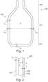
- Fig. 1 shows a schematical view of a glass container 100 according to an exemplary embodiment of the present invention.
- the glass container 100 comprises wall section 101 and a bottom section 102, wherein the wall section 101 and the bottom section 102 surround an inner volume Vi, wherein at least the wall section 101 comprises a tempered section 103 having a wall thickness tw between 1,1 mm and 2,3 mm.
- the glass container 100 describes in the shown embodiment a glass bottle for liquid or solid material, such as beverages or other disclose or solid food articles. Additionally, the glass container 100 comprises a bottleneck section 104 having an opening for filling the container 100.
- At least the wall section 101 comprises the tempered section 103.
- the complete wall 101 section forms the tempered section 103.
- the tempered section 104 has a wall thickness between 1,1 mm and 2,3 mm. Hence, the internal stress of the glass container 100 during cooling is reduced so that a tempered section 104 can be provided having less inner defects and at the same time providing proper impact resistance.
- a first wall thickness tw1 and an opposite second wall thickness tw2 of the tempered section 103 at a predefined distance to the bottom section comprises a relation of 1:2.
- the wall section 101 forms a hollow cylinder which is close by the bottom section 102.
- the bottom section 102 may form a cylindrical, rectangle or polygonal base/ground area of the cylindrical wall section 101.
- the wall thickness tw1 of a first wall section at a certain distance to the bottom section 102 differs to the wall thickness tw2 of a second wall section being located at the same distance to the bottom section 102.
- the bottom section 102 comprises also a bottom tempered section, wherein a thickness relation between the wall thickness tw1, tw2 of the wall tempered section 103 and the bottom thickness tB of the bottom tempered section is between 2 and 4,5.
- the bottom section 102 comprises a bottom thickness tb between 2 mm and 5 mm. Specifically, the thickness tb of the bottom section 102 interacts as well with the tempered section 103 since due to the cooling speed of the glass container 100 during tempering, respective stress in the temper section 103 affected by the thickness of the bottom section 102 can appear.
- the material of the glass container 100 comprises more than at least 10%, in particular more than 12 %, sodium carbonate.
- Fig. 2 shows a schematic overview a sandwich structure of a glass container 1000 according to an exemplary embodiment of the present invention.
- the tempered section 103 forms a sandwich structure 200 comprising an outer compression stress layer 201 and an inner tensile stress layer 202. Specifically, by controlling the cooling of the inner and outer surface of the tempered section 103, specific layers 201, 202, 203 having different prestressed characteristics can be generated.
- the sandwich structure comprises an inner compression stress layer 203, wherein the inner tensile stress layer 202 is arranged between the outer compression stress layer 201 and the inner compression stress layer 203.
- the shown structure can be generated, specifically a sandwich structure 200 having the central inner compression stress layer 202 covered by the outer and inner tensile stress layer 201, 203.
- the central tensile stress layer 202 is fully covered and protected by the surrounding compression stress layers 201, 203.
- the inner compression stress layer 203 faces the inner volume Vi and is in particular in contact with the inner volume Vi of the glass container.
- the interaction between the outer compression stress layer 201, the inner tensile stress layer 202 and the inner compression stress layer 203 forms a robust sandwich structure 200.
- the outer compression stress layer 201 has a wall thickness to of 300 ⁇ m to 400 ⁇ m.
- the inner tensile stress layer 202 has a wall thickness tm of 700 ⁇ m to 1600 ⁇ m.
- the inner compression stress layer 203 has a wall thickness ti of 20 ⁇ m to 100 ⁇ m.
- the thickness of the specific layers 201, 202, 203 can be adjusted by respective cooling power applied to the inner side or the other side of the glass container 100 during tempering. It has found out, that by providing the inner tensile stress layer 202 thicker, in particular by the above-mentioned values, with respect to the thinner outer compression stress layers 201, 203, a robust sandwich 200 and tempered section 103, respectively, can be achieved.
- the bottom section 2 may also form a bottom sandwich structure comprising a bottom outer compression stress layer and a bottom inner tensile stress layer similar as shown in Fig. 2 .
- the bottom outer compression stress layer has a wall thickness of 300 ⁇ m to 400 ⁇ m
- a bottom inner tensile stress layer has a wall thickness of 700 ⁇ m to 4700 ⁇ m
- a bottom inner compression stress layer has a bottom wall thickness of 20 ⁇ m to 100 ⁇ m.
- Fig. 3 illustrates a diagram of respective pretensioned compressing layers 201, 203 and a tension layer 202 according to an exemplary embodiment of the present invention.
- the wall thickness is defined at a location where the smallest thickness of the wall section is existent.
- the y-axis describes the measured pretensioned stress level of the layers 201, 202, 203, wherein the tensile stress has a positive sign and the compression stress has a negative sign.
- the outer compression stress layer 201 comprises a maximum pretensioned compression stress -55 MPa.
- the inner tensile stress layer 202 comprises a maximum pretensioned tensile stress of 25 MPa.
- the inner compression stress layer 203 comprises a maximum pretensioned compression stress of -25 MPa.
- the maximum compression stress of the outer compression stress layer 201 and inner compression stress layer 203 as formed at the outer surfaces of the tempered section 103.
- the maximum tensile stress of the inner compression stress layer 202 is formed in the center (regarding the thickness of the tempered section 103) of the inner tensile stress layer 202.
- the values for the tensile stress and the compression stress define the maximum stress values within a respective layer.
- the compression stress of a compression stress layers 201, 203 reduces in the direction to the inner tensile stress layer 202 and vice versa.
- the value for the pretensioned stress is 0.
Landscapes
- Engineering & Computer Science (AREA)
- Chemical & Material Sciences (AREA)
- Physics & Mathematics (AREA)
- Ceramic Engineering (AREA)
- Mechanical Engineering (AREA)
- Thermal Sciences (AREA)
- Materials Engineering (AREA)
- Organic Chemistry (AREA)
- Mathematical Physics (AREA)
- Details Of Rigid Or Semi-Rigid Containers (AREA)
- Surface Treatment Of Glass (AREA)
- Containers Having Bodies Formed In One Piece (AREA)
Claims (15)
- Glasbehälter (100), aufweisend:
einen Wandabschnitt (101) und einen Bodenabschnitt (102),wobei der Wandabschnitt (101) und der Bodenabschnitt (102) ein Innenvolumen umgeben,wobei zumindest der Wandabschnitt (101) einen gehärteten Abschnitt (103) mit einer Wanddicke (tw) zwischen 1,1 mm und 2,3 mm aufweist,wobei der Bodenabschnitt (102) einen gehärteten Bodenabschnitt aufweist,wobei ein Dickenverhältnis zwischen der Wanddicke (tw) des gehärteten Wandabschnitts (103) und der Bodendicke des gehärteten Bodenabschnitts zwischen 2 und 4,5 liegt. - Glasbehälter (100) nach Anspruch 1,
wobei der gehärtete Abschnitt (103) eine Wanddicke (tw) zwischen 1,3 mm und 2 mm aufweist. - Glasbehälter (100) nach Anspruch 1 oder 2,
wobei eine erste Wanddicke (t1) und eine entgegengesetzte zweite Wanddicke (t2) des gehärteten Abschnitts (103) in einem vorgegebenen Abstand zum Bodenabschnitt (102) ein Verhältnis von 1:2, insbesondere 1:1,5, aufweisen. - Glasbehälter (100) nach einem der Ansprüche 1 bis 3,
wobei der gehärtete Abschnitt (103) eine Sandwichstruktur (200) bildet, die eine äußere Druckspannungsschicht (201) und eine innere Zugspannungsschicht (202) aufweist. - Glasbehälter (100) nach Anspruch 4,wobei die äußere Druckspannungsschicht (201) eine Wanddicke (to) von 300 µm bis 400 µm, insbesondere 340 µm bis 360 µm, aufweist, und/oderwobei die innere Zugspannungsschicht (202) eine Wanddicke (tm) von 700 µm bis 1600 µm, insbesondere 900 µm bis 1200 µm, aufweist.
- Glasbehälter (100) nach Anspruch 4 oder 5,wobei die äußere Druckspannungsschicht (201) eine vorgespannte Druckspannung von -80 MPa bis -5 MPa, insbesondere -70 bis -20 MPa, weiter insbesondere -60 MPa bis -50 MPa, aufweist, und/oderwobei die innere Zugspannungsschicht (202) eine vorgespannte Zugspannung von 10 MPa bis 70 MPa, insbesondere 15 bis 50 MPa, weiter insbesondere 20 MPa bis 30 MPa, aufweist.
- Glasbehälter (100) nach einem der Ansprüche 4 bis 6,wobei die Sandwichstruktur (200) ferner eine innere Druckspannungsschicht (203) aufweist,wobei die innere Zugspannungsschicht (202) zwischen der äußeren Druckspannungsschicht (201) und der inneren Druckspannungsschicht (203) angeordnet ist.
- Glasbehälter (100) nach Anspruch 7,wobei die innere Druckspannungsschicht (203) eine Wanddicke (ti) von 20 µm bis 100 µm, insbesondere 40 µm bis 60 µm, aufweist,wobei die innere Druckspannungsschicht (203) eine vorgespannte Druckspannung von -60 MPa bis -5 MPa, insbesondere -50 bis -15 MPa, weiter insbesondere -30 MPa bis -20 MPa, aufweist.
- Glasbehälter (100) nach einem der Ansprüche 1 bis 8,
wobei der Bodenabschnitt (102) eine Bodendicke zwischen 2 mm und 5 mm, insbesondere 2,5 mm bis 4 mm, aufweist. - Glasbehälter (100) nach einem der Ansprüche 1 bis 9,
wobei ein Dickenverhältnis zwischen der Wanddicke (tw) des gehärteten Wandabschnitts (103) und der Bodendicke des gehärteten Bodenabschnitts zwischen 2,5 und 3,5 liegt. - Glasbehälter (100) nach Anspruch 10,wobei der gehärtete Bodenabschnitt eine Bodensandwichstruktur bildet, die eine äußere Bodendruckspannungsschicht (201) und eine innere Bodenzugspannungsschicht (202) aufweist,wobei die äußere Bodendruckspannungsschicht (201) eine Wanddicke (to) von 300 µm bis 400 µm, insbesondere 340 µm bis 360 µm, aufweist, und/oder wobei die innere Bodenzugspannungsschicht (202) eine Wanddicke (tm) von 700 µm bis 4700 µm, insbesondere 900 µm bis 4000 µm, aufweist, und/oder wobei die äußere Bodendruckspannungsschicht (201) eine vorgespannte Druckspannung von -80 MPa bis -5 MPa, insbesondere -70 bis -20 MPa, weiter insbesondere -60 MPa bis -50 MPa, aufweist, und/oderwobei die innere Bodenzugspannungsschicht (202) eine vorgespannte Zugspannung von 10 MPa bis 70 MPa, insbesondere 15 MPa bis 50 MPa, weiter insbesondere 20 MPa bis 30 MPa, aufweist.
- Glasbehälter (100) nach Anspruch 11,wobei die Bodensandwichstruktur ferner eine innere Bodendruckspannungsschicht (203) aufweist,wobei die innere Bodenzugspannungsschicht (202) zwischen der äußeren Bodendruckspannungsschicht (201) und der inneren Bodendruckspannungsschicht (203) angeordnet ist,wobei die innere Bodendruckspannungsschicht (203) eine Bodenwanddicke (ti) von 20 µm bis 100 µm, insbesondere 40 µm bis 60 µm, aufweist,wobei die innere Bodendruckspannungsschicht (203) eine vorgespannte Druckspannung von -60 MPa bis -5 MPa, insbesondere -50 bis -15 MPa, weiter insbesondere -30 MPa bis -20 MPa, aufweist.
- Glasbehälter (100) nach einem der Ansprüche 1 bis 12, ferner aufweisend:
einen Flaschenhalsabschnitt (104), der eine Öffnung zwischen der Umgebung und dem Innenvolumen (Vi) aufweist,wobei der Wandabschnitt zwischen dem Bodenabschnitt (102) und dem Flaschenhalsabschnitt (104) ausgebildet ist,wobei der Flaschenhalsabschnitt (104) einen gehärteten Bodenabschnitt aufweist, der eine Flaschenhalssandwichstruktur bildet, die eine äußere Flaschenhalsdruckspannungsschicht (201) und eine innere Flaschenhalszugspannungsschicht (202) aufweist,wobei die Flaschenhalssandwichstruktur ferner insbesondere eine innere Flaschenhalsdruckspannungsschicht (203) aufweist. - Glasbehälter (100) nach einem der Ansprüche 1 bis 13,
wobei das Material des Glasbehälters (100) mehr als mindestens 10 %, insbesondere mehr als 12 %, Natriumcarbonat aufweist. - Verfahren zum Herstellen eines Glasbehälters (100) nach einem der Ansprüche 1 bis 14, das Verfahren aufweisend:Bereitstellen eines Glasbehälters (100) mit einem Wandabschnitt (101) und einem Bodenabschnitt (102),
wobei der Wandabschnitt (101) und der Bodenabschnitt (102) ein Innenvolumen (Vi) umgeben,Bilden eines gehärteten Abschnitts (103) zumindest in dem Wandabschnitt (101) durch thermische Behandlung,wobei der gehärtete Abschnitt (103) eine Wanddicke (tw) zwischen 1,1 mm und 2,3 mm aufweist,wobei der Bodenabschnitt (102) einen gehärteten Bodenabschnitt aufweist,wobei ein Dickenverhältnis zwischen der Wanddicke (tw) des gehärteten Wandabschnitts (103) und der Bodendicke des gehärteten Bodenabschnitts zwischen 2 und 4,5 liegt.
Priority Applications (1)
| Application Number | Priority Date | Filing Date | Title |
|---|---|---|---|
| HRP20251082TT HRP20251082T1 (hr) | 2023-03-17 | 2024-03-15 | Boca od kaljenog stakla s tankom debljinom stijenke |
Applications Claiming Priority (1)
| Application Number | Priority Date | Filing Date | Title |
|---|---|---|---|
| EP23162639.1A EP4431471A1 (de) | 2023-03-17 | 2023-03-17 | Gehärtete glasflasche mit dünner wanddicke |
Publications (3)
| Publication Number | Publication Date |
|---|---|
| EP4431473A1 EP4431473A1 (de) | 2024-09-18 |
| EP4431473B1 true EP4431473B1 (de) | 2025-06-25 |
| EP4431473C0 EP4431473C0 (de) | 2025-06-25 |
Family
ID=85704663
Family Applications (2)
| Application Number | Title | Priority Date | Filing Date |
|---|---|---|---|
| EP23162639.1A Pending EP4431471A1 (de) | 2023-03-17 | 2023-03-17 | Gehärtete glasflasche mit dünner wanddicke |
| EP24163785.9A Active EP4431473B1 (de) | 2023-03-17 | 2024-03-15 | Gehärtete glasflasche mit dünner wanddicke |
Family Applications Before (1)
| Application Number | Title | Priority Date | Filing Date |
|---|---|---|---|
| EP23162639.1A Pending EP4431471A1 (de) | 2023-03-17 | 2023-03-17 | Gehärtete glasflasche mit dünner wanddicke |
Country Status (9)
| Country | Link |
|---|---|
| EP (2) | EP4431471A1 (de) |
| AU (1) | AU2024238982A1 (de) |
| ES (1) | ES3036517T3 (de) |
| HR (1) | HRP20251082T1 (de) |
| HU (1) | HUE073019T2 (de) |
| MD (1) | MD20250042A2 (de) |
| MX (1) | MX2025010907A (de) |
| PL (1) | PL4431473T3 (de) |
| WO (1) | WO2024194184A1 (de) |
Citations (9)
| Publication number | Priority date | Publication date | Assignee | Title |
|---|---|---|---|---|
| JPH03285836A (ja) | 1990-04-02 | 1991-12-17 | Ishizuka Glass Co Ltd | 耐熱性ガラス容器の製造方法 |
| WO2011150065A2 (en) | 2010-05-25 | 2011-12-01 | Emhart Glass S.A. | Bottom cooler for a post-manufacture glass container thermal strengthening station |
| KR20130068315A (ko) | 2011-12-15 | 2013-06-26 | 한국세라믹기술원 | 소다라임계 저팽창 내열유리 및 그 제조방법 |
| US20150147497A1 (en) | 2013-11-25 | 2015-05-28 | Owens-Brockway Glass Container Inc. | Soda-Lime Glass from 100% Recycled Glass-Forming Materials |
| CN106746634A (zh) | 2016-12-21 | 2017-05-31 | 柳州市昌泉贸易有限公司 | 一种玻璃瓶及其制作方法 |
| US9850162B2 (en) | 2012-02-29 | 2017-12-26 | Corning Incorporated | Glass packaging ensuring container integrity |
| US20210060256A1 (en) | 2019-09-04 | 2021-03-04 | Schott Schweiz Ag | Dead end container and container assembly with dead end container |
| US20220017399A1 (en) | 2020-07-20 | 2022-01-20 | Corning Incorporated | Stress features for crack redirection and protection in glass containers |
| US11279647B2 (en) | 2017-11-30 | 2022-03-22 | Corning Incorporated | Glass articles made from laminated glass tubing and systems and methods for converting laminated glass tubing into the glass articles |
Family Cites Families (6)
| Publication number | Priority date | Publication date | Assignee | Title |
|---|---|---|---|---|
| DE102016123147A1 (de) * | 2016-11-30 | 2018-05-30 | Schott Ag | Haltestruktur zum gleichzeitigen Halten einer Mehrzahl von Vials, Verwendung hiervon sowie Verfahren zur Behandlung solcher Vials |
| CN108218222A (zh) * | 2016-12-14 | 2018-06-29 | 江苏浦亚照明科技股份有限公司 | 一种绿色玻璃灯罩的制造方法 |
| CN106630609A (zh) * | 2016-12-21 | 2017-05-10 | 柳州市昌泉贸易有限公司 | 一种艺术玻璃瓶及其制作方法 |
| US12338164B2 (en) * | 2017-08-02 | 2025-06-24 | National Research Council Of Canada | Boron nitride nanotube-silicate glass composites |
| US20190161399A1 (en) * | 2017-11-30 | 2019-05-30 | Corning Incorporated | Glass articles with low-friction coatings and methods for coating glass articles |
| EP3842025B1 (de) * | 2019-12-20 | 2025-03-19 | SCHOTT Pharma AG & Co. KGaA | Glasbehälter mit einem glasboden mit verbesserten eigenschaften |
-
2023
- 2023-03-17 EP EP23162639.1A patent/EP4431471A1/de active Pending
-
2024
- 2024-03-15 HU HUE24163785A patent/HUE073019T2/hu unknown
- 2024-03-15 HR HRP20251082TT patent/HRP20251082T1/hr unknown
- 2024-03-15 MD MDA20250042A patent/MD20250042A2/ro unknown
- 2024-03-15 WO PCT/EP2024/056978 patent/WO2024194184A1/en not_active Ceased
- 2024-03-15 PL PL24163785.9T patent/PL4431473T3/pl unknown
- 2024-03-15 AU AU2024238982A patent/AU2024238982A1/en active Pending
- 2024-03-15 ES ES24163785T patent/ES3036517T3/es active Active
- 2024-03-15 EP EP24163785.9A patent/EP4431473B1/de active Active
-
2025
- 2025-09-15 MX MX2025010907A patent/MX2025010907A/es unknown
Patent Citations (9)
| Publication number | Priority date | Publication date | Assignee | Title |
|---|---|---|---|---|
| JPH03285836A (ja) | 1990-04-02 | 1991-12-17 | Ishizuka Glass Co Ltd | 耐熱性ガラス容器の製造方法 |
| WO2011150065A2 (en) | 2010-05-25 | 2011-12-01 | Emhart Glass S.A. | Bottom cooler for a post-manufacture glass container thermal strengthening station |
| KR20130068315A (ko) | 2011-12-15 | 2013-06-26 | 한국세라믹기술원 | 소다라임계 저팽창 내열유리 및 그 제조방법 |
| US9850162B2 (en) | 2012-02-29 | 2017-12-26 | Corning Incorporated | Glass packaging ensuring container integrity |
| US20150147497A1 (en) | 2013-11-25 | 2015-05-28 | Owens-Brockway Glass Container Inc. | Soda-Lime Glass from 100% Recycled Glass-Forming Materials |
| CN106746634A (zh) | 2016-12-21 | 2017-05-31 | 柳州市昌泉贸易有限公司 | 一种玻璃瓶及其制作方法 |
| US11279647B2 (en) | 2017-11-30 | 2022-03-22 | Corning Incorporated | Glass articles made from laminated glass tubing and systems and methods for converting laminated glass tubing into the glass articles |
| US20210060256A1 (en) | 2019-09-04 | 2021-03-04 | Schott Schweiz Ag | Dead end container and container assembly with dead end container |
| US20220017399A1 (en) | 2020-07-20 | 2022-01-20 | Corning Incorporated | Stress features for crack redirection and protection in glass containers |
Non-Patent Citations (8)
| Title |
|---|
| "Doctoral Thesis, University of Leicester", 1 February 2016, article EARP RICHARD W: "The Effect of Thermal Tempering Processes on the Sharpness and Injury Potential of Pint Glasses", XP093383132 |
| ANONYMOUS: "AMALFI - Invitation au farniente", DURALEX (VIA THE WAYBACK MACHINE), 28 March 2016 (2016-03-28), XP093383135, Retrieved from the Internet <URL:https://web.archive.org/web/20160328040747/http://www.duralex.com/amalfi.html > |
| ANONYMOUS: "Bormioli Rocco Lyon verre à eau 21cl, empilable, trempée, 6 verres", AMAZON, 22 March 2019 (2019-03-22), XP093383134, Retrieved from the Internet <URL:https://www.amazon.fr/Bormioli-Rocco-empilable-tremp%25C3%25A9e-verres/dp/B005AFBEI2?language=fr_FR> |
| ANONYMOUS: "Nonic Pint Glass", DIMENSIONS.COM (VIA THE WAYBACK MACHINE), 18 August 2022 (2022-08-18), XP093383083, Retrieved from the Internet <URL:https://web.archive.org/web/20220818071621/www.dimensions.com/element/nonic-pint-glass> |
| D13 - mesures Bormioli Rocco. verre identique a celui presente dans E3 |
| D15 - mesures Duralex Picardie collection Amalfi |
| D16 - DURALEX: "Gobelet 9 cl", 28 March 2016 (2016-03-28), Retrieved from the Internet <URL:https://web.archive.org/web/20160328035045/http://www.duralex.com/?fon> [retrieved on 20260324] |
| D17 - mesures Duralex Picardie Collection Picardie |
Also Published As
| Publication number | Publication date |
|---|---|
| HUE073019T2 (hu) | 2025-12-28 |
| MD20250042A2 (ro) | 2026-01-31 |
| EP4431473A1 (de) | 2024-09-18 |
| WO2024194184A1 (en) | 2024-09-26 |
| EP4431471A1 (de) | 2024-09-18 |
| PL4431473T3 (pl) | 2025-09-29 |
| AU2024238982A1 (en) | 2025-09-11 |
| MX2025010907A (es) | 2026-01-07 |
| HRP20251082T1 (hr) | 2025-11-07 |
| ES3036517T3 (en) | 2025-09-19 |
| EP4431473C0 (de) | 2025-06-25 |
Similar Documents
| Publication | Publication Date | Title |
|---|---|---|
| KR101938446B1 (ko) | 용기의 무결성을 보장하는 유리 포장 | |
| CN116655262A (zh) | 具有高储能的应力分布的玻璃基制品及制造方法 | |
| KR20180036746A (ko) | 열적으로 강화된 자동차 유리 | |
| CN113232386A (zh) | 具有确定模量对比的层压玻璃制品及其形成方法 | |
| KR20110061516A (ko) | 글래스 롤 및 글래스 롤의 제조 방법 | |
| KR102512668B1 (ko) | 높은 접촉 저항성 가요성 초박형 유리 | |
| US12084373B2 (en) | Glass carriers for fan-out packaging having target coefficients of thermal expansion and methods for making the same | |
| JP2018512367A (ja) | レーザを用いてガラスを分断するための方法ならびに本発明により製造されたガラス製品 | |
| KR20200015456A (ko) | 높은 접촉 저항을 갖는 가요성 초박형 유리 | |
| EP0526263B1 (de) | Verbundscheibe und Verfahren zur ihrer Herstellung | |
| EP4431472B1 (de) | Gehärtete glasflasche mit sandwichstruktur | |
| US20190002330A1 (en) | Thermally strengthened automotive glass | |
| EP4431471A1 (de) | Gehärtete glasflasche mit dünner wanddicke | |
| CN112424136A (zh) | 用于微电子制造的载体 | |
| WO2025101449A1 (en) | Designed bottom and flange ring-off breakage of strengthened glass containers via geometrical features | |
| US11994700B2 (en) | Band-pass near-infrared (NIR) filter, method of production of a band-pass NIR filter and uses thereof | |
| Dingwall | Exploding Bottles | |
| KR20250121562A (ko) | 강화 유리 기반 물품 | |
| JP2003146677A (ja) | 照明用ガラス管 | |
| LaCourse et al. | Containers for the 21st century: Opportunities for lightweighting | |
| Jaime et al. | A comparison of the performance of lightweight glass containers manufactured by the P&B and B&B processes | |
| US12286262B2 (en) | Glass vessel | |
| Ghering | Improving the Strength of Glass Containers Through Design | |
| JPH02208239A (ja) | 薄肉強化ガラス製品の製造方法 | |
| US20230127792A1 (en) | Glass container with a protective coating of acrylate urethane polymer deposited on an exterior surface of the glass container; method of producing such glass container and use of such glass container |
Legal Events
| Date | Code | Title | Description |
|---|---|---|---|
| REG | Reference to a national code |
Ref country code: HR Ref legal event code: TUEP Ref document number: P20251082T Country of ref document: HR |
|
| PUAI | Public reference made under article 153(3) epc to a published international application that has entered the european phase |
Free format text: ORIGINAL CODE: 0009012 |
|
| STAA | Information on the status of an ep patent application or granted ep patent |
Free format text: STATUS: THE APPLICATION HAS BEEN PUBLISHED |
|
| STAA | Information on the status of an ep patent application or granted ep patent |
Free format text: STATUS: REQUEST FOR EXAMINATION WAS MADE |
|
| AK | Designated contracting states |
Kind code of ref document: A1 Designated state(s): AL AT BE BG CH CY CZ DE DK EE ES FI FR GB GR HR HU IE IS IT LI LT LU LV MC ME MK MT NL NO PL PT RO RS SE SI SK SM TR |
|
| 17P | Request for examination filed |
Effective date: 20240911 |
|
| RBV | Designated contracting states (corrected) |
Designated state(s): AL AT BE BG CH CY CZ DE DK EE ES FI FR GB GR HR HU IE IS IT LI LT LU LV MC ME MK MT NL NO PL PT RO RS SE SI SK SM TR |
|
| GRAP | Despatch of communication of intention to grant a patent |
Free format text: ORIGINAL CODE: EPIDOSNIGR1 |
|
| STAA | Information on the status of an ep patent application or granted ep patent |
Free format text: STATUS: GRANT OF PATENT IS INTENDED |
|
| INTG | Intention to grant announced |
Effective date: 20250131 |
|
| GRAS | Grant fee paid |
Free format text: ORIGINAL CODE: EPIDOSNIGR3 |
|
| GRAA | (expected) grant |
Free format text: ORIGINAL CODE: 0009210 |
|
| STAA | Information on the status of an ep patent application or granted ep patent |
Free format text: STATUS: THE PATENT HAS BEEN GRANTED |
|
| AK | Designated contracting states |
Kind code of ref document: B1 Designated state(s): AL AT BE BG CH CY CZ DE DK EE ES FI FR GB GR HR HU IE IS IT LI LT LU LV MC ME MK MT NL NO PL PT RO RS SE SI SK SM TR |
|
| REG | Reference to a national code |
Ref country code: GB Ref legal event code: FG4D |
|
| REG | Reference to a national code |
Ref country code: CH Ref legal event code: EP |
|
| REG | Reference to a national code |
Ref country code: CH Ref legal event code: EP |
|
| REG | Reference to a national code |
Ref country code: IE Ref legal event code: FG4D |
|
| REG | Reference to a national code |
Ref country code: DE Ref legal event code: R096 Ref document number: 602024000240 Country of ref document: DE |
|
| U01 | Request for unitary effect filed |
Effective date: 20250725 |
|
| U07 | Unitary effect registered |
Designated state(s): AT BE BG DE DK EE FI FR IT LT LU LV MT NL PT RO SE SI Effective date: 20250801 |
|
| REG | Reference to a national code |
Ref country code: ES Ref legal event code: FG2A Ref document number: 3036517 Country of ref document: ES Kind code of ref document: T3 Effective date: 20250919 |
|
| PG25 | Lapsed in a contracting state [announced via postgrant information from national office to epo] |
Ref country code: NO Free format text: LAPSE BECAUSE OF FAILURE TO SUBMIT A TRANSLATION OF THE DESCRIPTION OR TO PAY THE FEE WITHIN THE PRESCRIBED TIME-LIMIT Effective date: 20250925 |
|
| PG25 | Lapsed in a contracting state [announced via postgrant information from national office to epo] |
Ref country code: RS Free format text: LAPSE BECAUSE OF FAILURE TO SUBMIT A TRANSLATION OF THE DESCRIPTION OR TO PAY THE FEE WITHIN THE PRESCRIBED TIME-LIMIT Effective date: 20250925 |
|
| REG | Reference to a national code |
Ref country code: SK Ref legal event code: T3 Ref document number: E 47033 Country of ref document: SK |
|
| REG | Reference to a national code |
Ref country code: GR Ref legal event code: EP Ref document number: 20250401901 Country of ref document: GR Effective date: 20251009 |
|
| REG | Reference to a national code |
Ref country code: HR Ref legal event code: T1PR Ref document number: P20251082 Country of ref document: HR |
|
| REG | Reference to a national code |
Ref country code: HU Ref legal event code: AG4A Ref document number: E073019 Country of ref document: HU |
|
| PG25 | Lapsed in a contracting state [announced via postgrant information from national office to epo] |
Ref country code: IS Free format text: LAPSE BECAUSE OF FAILURE TO SUBMIT A TRANSLATION OF THE DESCRIPTION OR TO PAY THE FEE WITHIN THE PRESCRIBED TIME-LIMIT Effective date: 20251025 |
|
| PG25 | Lapsed in a contracting state [announced via postgrant information from national office to epo] |
Ref country code: SM Free format text: LAPSE BECAUSE OF FAILURE TO SUBMIT A TRANSLATION OF THE DESCRIPTION OR TO PAY THE FEE WITHIN THE PRESCRIBED TIME-LIMIT Effective date: 20250625 |
|
| PLBI | Opposition filed |
Free format text: ORIGINAL CODE: 0009260 |
|
| REG | Reference to a national code |
Ref country code: CH Ref legal event code: L10 Free format text: ST27 STATUS EVENT CODE: U-0-0-L10-L00 (AS PROVIDED BY THE NATIONAL OFFICE) Effective date: 20260409 |
|
| REG | Reference to a national code |
Ref country code: HR Ref legal event code: ODRP Ref document number: P20251082 Country of ref document: HR Payment date: 20260313 Year of fee payment: 3 |
|
| PGFP | Annual fee paid to national office [announced via postgrant information from national office to epo] |
Ref country code: IE Payment date: 20260316 Year of fee payment: 3 |
|
| PGFP | Annual fee paid to national office [announced via postgrant information from national office to epo] |
Ref country code: HR Payment date: 20260313 Year of fee payment: 3 |
|
| PGFP | Annual fee paid to national office [announced via postgrant information from national office to epo] |
Ref country code: CZ Payment date: 20260313 Year of fee payment: 3 |
|
| PGFP | Annual fee paid to national office [announced via postgrant information from national office to epo] |
Ref country code: GR Payment date: 20260318 Year of fee payment: 3 Ref country code: PL Payment date: 20260313 Year of fee payment: 3 |
|
| PGFP | Annual fee paid to national office [announced via postgrant information from national office to epo] |
Ref country code: SK Payment date: 20260313 Year of fee payment: 3 |
|
| U20 | Renewal fee for the european patent with unitary effect paid |
Year of fee payment: 3 Effective date: 20260325 |
|
| 26 | Opposition filed |
Opponent name: SOYLU PATENT A.S. Effective date: 20260325 Opponent name: VERALLIA PACKAGING Effective date: 20260325 |
|
| PLAX | Notice of opposition and request to file observation + time limit sent |
Free format text: ORIGINAL CODE: EPIDOSNOBS2 |