EP4431418A1 - Sicherheitsklappe zum verschliessen eines unterirdischen behälterfutters - Google Patents
Sicherheitsklappe zum verschliessen eines unterirdischen behälterfutters Download PDFInfo
- Publication number
- EP4431418A1 EP4431418A1 EP23215896.4A EP23215896A EP4431418A1 EP 4431418 A1 EP4431418 A1 EP 4431418A1 EP 23215896 A EP23215896 A EP 23215896A EP 4431418 A1 EP4431418 A1 EP 4431418A1
- Authority
- EP
- European Patent Office
- Prior art keywords
- hatch
- casing
- pedal
- axis
- container
- Prior art date
- Legal status (The legal status is an assumption and is not a legal conclusion. Google has not performed a legal analysis and makes no representation as to the accuracy of the status listed.)
- Pending
Links
- 230000005484 gravity Effects 0.000 claims abstract description 20
- 239000002699 waste material Substances 0.000 claims description 16
- 230000002093 peripheral effect Effects 0.000 claims description 8
- 230000000903 blocking effect Effects 0.000 claims description 2
- 230000000694 effects Effects 0.000 description 5
- 238000000605 extraction Methods 0.000 description 4
- 238000003780 insertion Methods 0.000 description 4
- 230000037431 insertion Effects 0.000 description 4
- 240000008042 Zea mays Species 0.000 description 2
- 230000008901 benefit Effects 0.000 description 2
- 230000002441 reversible effect Effects 0.000 description 2
- 241001080024 Telles Species 0.000 description 1
- 238000004140 cleaning Methods 0.000 description 1
- 238000006073 displacement reaction Methods 0.000 description 1
- 230000007613 environmental effect Effects 0.000 description 1
- 238000012423 maintenance Methods 0.000 description 1
- 238000004519 manufacturing process Methods 0.000 description 1
- 239000002184 metal Substances 0.000 description 1
- 230000000750 progressive effect Effects 0.000 description 1
- 239000002994 raw material Substances 0.000 description 1
- 230000000007 visual effect Effects 0.000 description 1
- XLYOFNOQVPJJNP-UHFFFAOYSA-N water Substances O XLYOFNOQVPJJNP-UHFFFAOYSA-N 0.000 description 1
Images
Classifications
-
- B—PERFORMING OPERATIONS; TRANSPORTING
- B65—CONVEYING; PACKING; STORING; HANDLING THIN OR FILAMENTARY MATERIAL
- B65F—GATHERING OR REMOVAL OF DOMESTIC OR LIKE REFUSE
- B65F1/00—Refuse receptacles; Accessories therefor
- B65F1/14—Other constructional features; Accessories
- B65F1/1426—Housings, cabinets or enclosures for refuse receptacles
- B65F1/1447—Housings, cabinets or enclosures for refuse receptacles located underground
-
- B—PERFORMING OPERATIONS; TRANSPORTING
- B65—CONVEYING; PACKING; STORING; HANDLING THIN OR FILAMENTARY MATERIAL
- B65F—GATHERING OR REMOVAL OF DOMESTIC OR LIKE REFUSE
- B65F2210/00—Equipment of refuse receptacles
- B65F2210/148—Locking means
Definitions
- the present invention relates to waste management and more particularly to waste containers, placed at predetermined locations in sites dedicated to waste collection, and which the competent authorities must empty at regular intervals. Since the regions, municipalities, etc., in charge of managing waste collection points are sensitive to solutions that do not harm the visual harmony of the places, there is a generalization of sites in which the containers are buried, with only external filling mouths remaining visible.
- the waste containers are therefore placed invisibly underground, placed in underground volumes located below ground level and equipped to receive and house them.
- the underground volume is in practice equipped with a fixed casing remaining in the ground, constituting the walls of the underground volume and in which the waste container is placed.
- a safety system is provided whose function is to automatically close the upper opening of the casing, at ground level, as soon as the waste container is removed.
- the safety system does not have any elements at or near the bottom of the casing, which often contains waste and/or water that could alter the operation of such a system, to the detriment of the safety of the workers. This also makes it easier to maintain the system.
- the present invention is therefore also developed with a view to reducing the resources used.
- the present design voluntarily departs from certain conventional solutions in this field, for example by limiting the use of counterweight systems.
- EP 2 336 053 discloses a closure system which has these characteristics, but which is based on a complex configuration comprising in particular mechanical parts requiring maintenance, some of the parts being moreover liable to break following normal wear.
- the design of the invention is much simpler and, in practice, much more robust.
- the mechanical locking/unlocking device comprises at least one gravity mechanism provided with at least one member movable by gravity in a first direction actuating a lock blocking the hatch when it is in the closed position, and configured so that when the bottom of the container is placed on the hatch, said bottom of the container actuates said at least one movable member of the gravity mechanism in a direction opposite to the first direction capable of unlocking the hatch.
- the mechanism is further designed so that reverse movements/displacements of these components are possible as soon as the container, even empty, is placed in contact with them, in order to allow unlocking of each hatch.
- the lock is also actuated in the opposite direction, in the direction of unlocking the hatch.
- the gravity mechanism comprises a movable pedal integrated into the hatch, freely articulated relative to the hatch along an axis of rotation positioned between two asymmetrical parts of the pedal and making it capable of tilting by gravity between a first position inclined relative to the hatch when the latter is in the horizontal closing position, and a second position integrated into the hatch, flush with its external surface, when the hatch is in the vertical open position in the vicinity of the walls of the casing.
- the lock then consists of a rod articulated to one of the parts of said pedal and having a free end capable of being housed in a housing secured to the casing when the pedal is in its first position inclined relative to the hatch in the closing position.
- the axis of rotation of the pedal is oriented in an oblique direction relative to the sides of the rectangular trapdoor. This direction facilitates the implementation of the locking by the rod, as will appear more clearly in the rest of the description.
- the rod forming a lock may be provided parallel to the longitudinal direction of the pedal and articulated in the vicinity of the free end of the part of the pedal which pivots under the trapdoor, the pivot axis of said rod being parallel to the axis of rotation of the pedal.
- the tilting of the pedal is then at least partially transformed into a rectilinear movement of the rod towards its locking housing.
- the rod is guided in the trapdoor, at its free end, by an orifice made in an edge of the trapdoor perpendicular to the axis of rotation of the trapdoor.
- the trapdoor When the trapdoor is in the horizontal closed position, the free end of said rod - guided by this orifice - protrudes towards a window secured to the casing and placed in the vicinity of the opening of the latter, in order to be housed in said window, for example oblong.
- two pedals are provided in each hatch, arranged symmetrically with respect to a median axis of said hatch perpendicular to the axis of rotation of the hatch and in the vicinity of the corners of said hatch distal to said axis of rotation.
- the pedals are placed near the two free corners of each hatch, so that the locking rods protrude from the side edges towards the casing in the vicinity of these corners.
- the closing system comprises in practice two homologous hatches whose axes of rotation are placed opposite each other. There is then symmetry of the configuration with respect to a plane passing between and in the middle of the two free end edges of the hatches.
- each hatch is rotatably mounted in a rectangular frame fitted to the upper opening of the casing.
- This is a frame, for example made of metal, which covers the upper mouth of the casing and is held fixed there without necessarily being mechanically fixed there.
- each hatch has two pivot hinges connecting it to the frame, a cylinder constituting the means for returning the hatch to its closed position being arranged between the hinges.
- this frame which has windows allowing the housing of the free ends of the rods articulated to the pedals, which are inserted there to lock the hatches in the horizontal closing position.
- This rectangular frame also fulfills additional functions: thus, it includes a support rim on the peripheral edge of the upper opening of the casing, and two truncated pyramid sections, a first proximal section of the rim widening towards said rim and a second inverted distal section distal to the rim widening towards the bottom of the casing. These two sections act as means of guiding the waste container during its movements, since they allow in particular the centering of said container when inserted into the casing for the first, and when extracted for the second.
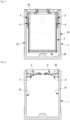
- the casing 1 is designed so that a container 2 can be placed there (present only in figure 1 ), associated with an external mouth (not shown) by means of which users pour their waste into the container 2.
- the hatches 3, 3' of the closing system are pressed against the walls of the container 2 by the action of the jacks 4, 4'.
- these hatches 3, 3' are returned to the horizontal position of closing of the casing 1 by jacks 4, 4', and blocked in this position by a gravity locking mechanism which is the subject of the present invention.
- the locked closing position of the hatches 3, 3' also appears in figure 3 .
- FIG 4 also shows more precisely the configuration of the closing hatches 3, 3' and their articulation to a frame 20 also appearing partially in figure 7 and in full in figure 8 , and which is placed around the perimeter of the upper opening of the casing 1.
- the hatches 3, 3' are made up of rectangular panels hinged in two places to said frame 20, so as to be able to pivot around a horizontal axis between at least their opening position as shown in figure 4 and their closing position appearing in figure 3 This latter position makes it possible to obstruct the underground cavity delimited by the casing 1 during the emptying of the container 2, and therefore prevents any accident.
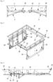
- each pedal pivots about an axis 31, on either side of which it has an asymmetrical configuration which precisely allows it to tilt under the effect of gravity. This may result from parts having shapes which are different on each side of the axis 31, as in the figures, in which the pedal 30 has a substantially triangular configuration in longitudinal section, or from an offset positioning of the axis 31 relative to the middle of the pedal 30.
- the heaviest portion of the pedal (here the one which includes the base of the triangle) causes it to tilt in the direction F. Its lightest portion protrudes from the surface of the upper face (as in figures 3, 5 And 6 ), while its heaviest portion sinks (the most important of the triangle in section) below the lower face of the hatch 3, 3'.
- a rod 33 is articulated about an axis 32 placed at the free end of the heaviest part which plunges under the hatch 3, 3'.
- This rod is, at its end opposite the articulation 32, guided in an orifice 34 made in one of the lateral edges 35 of the hatch 3, 3'.
- Each hatch 3, 3' comprises in the example illustrated two corner pedals 30, so that when the two hatches 3, 3' are returned by the jacks to the horizontal position, four pedals form protuberances protruding from the upper face of the double hatch 3, 3' which is in a position obstructing the upper opening of the casing 1.
- the ends of the rods 33 lock the hatches in the windows 21.
- this "floor” consisting of the hatches 3, 3' must be able to support a load of 150 kg at any point without opening.
- the solution presented does not, however, prevent the empty container, carried by the crane, from being lowered again, since its flat-looking bottom 28 (see in figure 1 ) lowers the parts of the pedals 30 which protrude from said "ground”, thereby causing all the pedals 30 to pivot in the opposite direction simultaneously, in the direction of the arrow F'.
- This gravity system with pedal 30 and locking/unlocking rod 33 is not perpendicular to the housing - that is to say to the window 21 made in the peripheral frame 20 - in which it is locked.
- the rod 33 forms an angle with the wall of the frame 20 having the housing/window 21, as does the pedal 30, the angle being provided sufficient so that said pedal 30 can benefit from the gravitational effect and therefore position itself under the effect of gravity parallel and flush with the outer surface of the safety hatches 3, 3' when the latter are in a vertical position inside the casing 1. If the pedal 30 and the rod 33 were oriented perpendicular to the proximal wall of the frame 20, controlling the movements of the pedal 30 and the movements of the rod 33 would be complicated to manage. If the pedal 30 is oriented perpendicular to the axis of rotation of the hatch 3, 3', managing the rod 33 acting as a lock is impossible in the configuration presented.
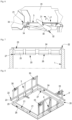
- the hatches 3, 3' are fixed on the frame 20 arranged on the upper periphery of the fixed casing 1.
- This frame 20 has a particular profile, for example visible in Figures 7 and 8 (but also in Figures 4 and 5 ), comprising in section different segments with different orientations in particular so that in three dimensions, certain functions of the frame 20 are ensured.
- this frame is designed to facilitate the guiding of the container 2 during insertion as well as extraction.
- the frame comprises, in a vertical direction, inclined portions which make it somewhat frustoconical from top to bottom but also from bottom to top.
- these “truncated” portions are in reality pyramid truncates, in this case separated by a vertical portion and oriented opposite to each other. They make it possible to guide the waste container 2 when the latter is replaced downhill in its fixed casing 1, but also to prevent the lower part of the buried container 2 from catching the frame 20 too abruptly when the waste container 2 is lifted to be emptied.
- the profile of the frame 20 first comprises a horizontal flat edge 22 which rests on the upper peripheral edge of the casing, followed by a small portion 23 in an upper vertical strip which fits inside said casing 1 and allows good positioning of the frame 20 there.
- a first portion in the shape of a truncated pyramid 24 forming a sort of “cone” for guiding insertion is separated by a median vertical strip 25 from the second portion in the shape of a truncated pyramid 26 oriented in an inverted manner in order to guide extraction.
- a lower edge/skirt 27 rises towards the walls of the casing 1.
- the assembly forming the frame 20 is in reality simply placed on said fixed casing 1.
- the small clearances between the interior vertical walls of the casing 1 and the vertical strip 23 on the one hand and the free edge of the lower border 27 on the other hand mean that it is not necessary to fix the frame 20 to prevent it from being disengaged when the container 2 is lifted. If disengagement forces are applied to it, the profile of the frame 20 is in fact designed in such a way that it reacts by bracing itself in the fixed casing 1, in particular at the level of the peripheral skirt 27, and remains in place.
Landscapes
- Engineering & Computer Science (AREA)
- Mechanical Engineering (AREA)
- Pressure Vessels And Lids Thereof (AREA)
- Catching Or Destruction (AREA)
- Closures For Containers (AREA)
- Refuse Receptacles (AREA)
Applications Claiming Priority (1)
| Application Number | Priority Date | Filing Date | Title |
|---|---|---|---|
| FR2302288A FR3146668B1 (fr) | 2023-03-13 | 2023-03-13 | Trappe(s) de sécurité pour fermer un cuvelage de conteneur enterré |
Publications (1)
| Publication Number | Publication Date |
|---|---|
| EP4431418A1 true EP4431418A1 (de) | 2024-09-18 |
Family
ID=86604155
Family Applications (1)
| Application Number | Title | Priority Date | Filing Date |
|---|---|---|---|
| EP23215896.4A Pending EP4431418A1 (de) | 2023-03-13 | 2023-12-12 | Sicherheitsklappe zum verschliessen eines unterirdischen behälterfutters |
Country Status (2)
| Country | Link |
|---|---|
| EP (1) | EP4431418A1 (de) |
| FR (1) | FR3146668B1 (de) |
Citations (5)
| Publication number | Priority date | Publication date | Assignee | Title |
|---|---|---|---|---|
| EP1714915A1 (de) * | 2005-04-19 | 2006-10-25 | Pel Ariesen | Automatische Verschlussvorrichtung für eine Grube |
| ES2301315B1 (es) * | 2005-11-30 | 2009-05-01 | Mbe Sotkon, S.L. | Sistema de seguridad para contenedores soterrados. |
| EP2336053A2 (de) | 2009-12-17 | 2011-06-22 | Koninklijke Bammens B.V. | Vorrichtung zum Verschliessen einer ebenerdigen Öffnung sowie Verfahren zum Heben eines Unterflurmüllbehälters in und aus einer ebenerdigen Öffnung |
| FR3058133A3 (fr) * | 2016-10-28 | 2018-05-04 | Fabrez S L | Dispositif d'ouverture et de fermeture pour plates-formes de securite de conteneurs souterrains |
| EP3733559A1 (de) * | 2019-04-30 | 2020-11-04 | Vconsyst Participaties B.V. | Abfallsammelvorrichtung, entladevorrichtung und verfahren zum entleeren der abfallsammeleinrichtung in die entladevorrichtung |
-
2023
- 2023-03-13 FR FR2302288A patent/FR3146668B1/fr active Active
- 2023-12-12 EP EP23215896.4A patent/EP4431418A1/de active Pending
Patent Citations (5)
| Publication number | Priority date | Publication date | Assignee | Title |
|---|---|---|---|---|
| EP1714915A1 (de) * | 2005-04-19 | 2006-10-25 | Pel Ariesen | Automatische Verschlussvorrichtung für eine Grube |
| ES2301315B1 (es) * | 2005-11-30 | 2009-05-01 | Mbe Sotkon, S.L. | Sistema de seguridad para contenedores soterrados. |
| EP2336053A2 (de) | 2009-12-17 | 2011-06-22 | Koninklijke Bammens B.V. | Vorrichtung zum Verschliessen einer ebenerdigen Öffnung sowie Verfahren zum Heben eines Unterflurmüllbehälters in und aus einer ebenerdigen Öffnung |
| FR3058133A3 (fr) * | 2016-10-28 | 2018-05-04 | Fabrez S L | Dispositif d'ouverture et de fermeture pour plates-formes de securite de conteneurs souterrains |
| EP3733559A1 (de) * | 2019-04-30 | 2020-11-04 | Vconsyst Participaties B.V. | Abfallsammelvorrichtung, entladevorrichtung und verfahren zum entleeren der abfallsammeleinrichtung in die entladevorrichtung |
Also Published As
| Publication number | Publication date |
|---|---|
| FR3146668A1 (fr) | 2024-09-20 |
| FR3146668B1 (fr) | 2025-03-14 |
Similar Documents
| Publication | Publication Date | Title |
|---|---|---|
| EP1081063A1 (de) | Vorrichtung zum automatisch durch Schwerkraft Verriegeln und Entriegeln des Deckels eines Behälters sowie Behälter mit einer derartigen Vorrichtung | |
| EP0509932A1 (de) | Verriegelungsvorrichtung für einen Behälter mit Deckel und Behälter mit einer solchen Vorrichtung | |
| EP1941821A1 (de) | Verteiler von nebeneinander angeordneten Rollen, der mit einer unteren Schiebeverschlussklappe ausgestattet ist | |
| EP1818458B1 (de) | Vorrichtung zum Verschliessen eines Schachts unter Verwendung einer auf dem Schacht montierten Platte | |
| FR2988707A1 (fr) | Poubelle enterree a barriere mobile. | |
| EP4431418A1 (de) | Sicherheitsklappe zum verschliessen eines unterirdischen behälterfutters | |
| EP0233090B1 (de) | Altglasbehälter | |
| FR2759680A1 (fr) | Conteneur de stockage d'objets | |
| EP2559822B1 (de) | Leuchtkasten mit beweglichem inneren Rahmen | |
| FR2983183A1 (fr) | Conteneur de collecte | |
| EP2743211B1 (de) | Einwurfschleuse für einen unterirdischen Behälter sowie Behälter mit einer solchen Einwurfschleuse | |
| FR2882735A1 (fr) | Benne amovible a echelles integrees pour le stockage et le transport de materiaux | |
| FR3058133A3 (fr) | Dispositif d'ouverture et de fermeture pour plates-formes de securite de conteneurs souterrains | |
| FR2579187A1 (fr) | Dispositif automatique de verrouillage/deverrouillage de la trappe de vidange d'une tremie et conteneur equipe d'un tel dispositif | |
| FR2728883A1 (fr) | Dispositif mecanique de securite pour l'utilisateur d'elevateur entre deux niveaux | |
| EP1564138B1 (de) | Übergangstreppe zwischen einer oberen und einer unteren Ebene eines Flugzeuges, und damit ausgerüstetes Flugzeug | |
| EP1091046A1 (de) | Verschlusseinrichtung eines Manlochs bzw. eines Inspektionschachtes | |
| FR2978960A1 (fr) | Conteneur de collecte des dechets dote d'un systeme d'actionnement de trappes perfectionne | |
| EP2159168A1 (de) | Müllschlucker zum automatischen und getrennten Sammeln von Müll | |
| FR2471334A1 (fr) | Conteneur notamment pour la collecte et le transfert de detritus ou autres objets perdus ou reutilisables | |
| FR2899253A1 (fr) | Dispositif de securite pour l'acces a une chambre technique situee sous une chaussee ou analogue | |
| FR2857948A1 (fr) | Conteneur destine a la collecte des dechets et enceinte le refermant | |
| FR3072953B1 (fr) | Systeme de collecte et de vidange de dechets. | |
| EP3400190B1 (de) | Stationärer schutzraum zur aufbewahrung von mindestens einer stromspeichereinheit | |
| FR2594712A1 (fr) | Destructeur de documents avec infrastructure similaire a une armoire |
Legal Events
| Date | Code | Title | Description |
|---|---|---|---|
| PUAI | Public reference made under article 153(3) epc to a published international application that has entered the european phase |
Free format text: ORIGINAL CODE: 0009012 |
|
| STAA | Information on the status of an ep patent application or granted ep patent |
Free format text: STATUS: THE APPLICATION HAS BEEN PUBLISHED |
|
| AK | Designated contracting states |
Kind code of ref document: A1 Designated state(s): AL AT BE BG CH CY CZ DE DK EE ES FI FR GB GR HR HU IE IS IT LI LT LU LV MC ME MK MT NL NO PL PT RO RS SE SI SK SM TR |
|
| STAA | Information on the status of an ep patent application or granted ep patent |
Free format text: STATUS: REQUEST FOR EXAMINATION WAS MADE |
|
| P01 | Opt-out of the competence of the unified patent court (upc) registered |
Free format text: CASE NUMBER: APP_62684/2024 Effective date: 20241125 |
|
| 17P | Request for examination filed |
Effective date: 20241212 |