EP4431366B1 - Rückkopplungssteuerung - Google Patents
Rückkopplungssteuerung Download PDFInfo
- Publication number
- EP4431366B1 EP4431366B1 EP23162286.1A EP23162286A EP4431366B1 EP 4431366 B1 EP4431366 B1 EP 4431366B1 EP 23162286 A EP23162286 A EP 23162286A EP 4431366 B1 EP4431366 B1 EP 4431366B1
- Authority
- EP
- European Patent Office
- Prior art keywords
- hydraulic
- vehicle
- hydraulic steering
- steering system
- siu
- Prior art date
- Legal status (The legal status is an assumption and is not a legal conclusion. Google has not performed a legal analysis and makes no representation as to the accuracy of the status listed.)
- Active
Links
Images


Classifications
-
- B—PERFORMING OPERATIONS; TRANSPORTING
- B62—LAND VEHICLES FOR TRAVELLING OTHERWISE THAN ON RAILS
- B62D—MOTOR VEHICLES; TRAILERS
- B62D6/00—Arrangements for automatically controlling steering depending on driving conditions sensed and responded to, e.g. control circuits
- B62D6/008—Control of feed-back to the steering input member, e.g. simulating road feel in steer-by-wire applications
-
- B—PERFORMING OPERATIONS; TRANSPORTING
- B62—LAND VEHICLES FOR TRAVELLING OTHERWISE THAN ON RAILS
- B62D—MOTOR VEHICLES; TRAILERS
- B62D5/00—Power-assisted or power-driven steering
- B62D5/001—Mechanical components or aspects of steer-by-wire systems, not otherwise provided for in this maingroup
- B62D5/005—Mechanical components or aspects of steer-by-wire systems, not otherwise provided for in this maingroup means for generating torque on steering wheel or input member, e.g. feedback
-
- B—PERFORMING OPERATIONS; TRANSPORTING
- B62—LAND VEHICLES FOR TRAVELLING OTHERWISE THAN ON RAILS
- B62D—MOTOR VEHICLES; TRAILERS
- B62D5/00—Power-assisted or power-driven steering
- B62D5/06—Power-assisted or power-driven steering fluid, i.e. using a pressurised fluid for most or all the force required for steering a vehicle
-
- B—PERFORMING OPERATIONS; TRANSPORTING
- B62—LAND VEHICLES FOR TRAVELLING OTHERWISE THAN ON RAILS
- B62D—MOTOR VEHICLES; TRAILERS
- B62D5/00—Power-assisted or power-driven steering
- B62D5/06—Power-assisted or power-driven steering fluid, i.e. using a pressurised fluid for most or all the force required for steering a vehicle
- B62D5/062—Details, component parts
- B62D5/063—Pump driven by vehicle engine
-
- B—PERFORMING OPERATIONS; TRANSPORTING
- B62—LAND VEHICLES FOR TRAVELLING OTHERWISE THAN ON RAILS
- B62D—MOTOR VEHICLES; TRAILERS
- B62D5/00—Power-assisted or power-driven steering
- B62D5/001—Mechanical components or aspects of steer-by-wire systems, not otherwise provided for in this maingroup
- B62D5/005—Mechanical components or aspects of steer-by-wire systems, not otherwise provided for in this maingroup means for generating torque on steering wheel or input member, e.g. feedback
- B62D5/006—Mechanical components or aspects of steer-by-wire systems, not otherwise provided for in this maingroup means for generating torque on steering wheel or input member, e.g. feedback power actuated
-
- B—PERFORMING OPERATIONS; TRANSPORTING
- B62—LAND VEHICLES FOR TRAVELLING OTHERWISE THAN ON RAILS
- B62D—MOTOR VEHICLES; TRAILERS
- B62D5/00—Power-assisted or power-driven steering
- B62D5/06—Power-assisted or power-driven steering fluid, i.e. using a pressurised fluid for most or all the force required for steering a vehicle
- B62D5/09—Power-assisted or power-driven steering fluid, i.e. using a pressurised fluid for most or all the force required for steering a vehicle characterised by means for actuating valves
- B62D5/091—Hydraulic steer-by-wire systems, e.g. the valve being actuated by an electric motor
-
- B—PERFORMING OPERATIONS; TRANSPORTING
- B62—LAND VEHICLES FOR TRAVELLING OTHERWISE THAN ON RAILS
- B62D—MOTOR VEHICLES; TRAILERS
- B62D5/00—Power-assisted or power-driven steering
- B62D5/06—Power-assisted or power-driven steering fluid, i.e. using a pressurised fluid for most or all the force required for steering a vehicle
- B62D5/30—Safety devices, e.g. alternate emergency power supply or transmission means to ensure steering upon failure of the primary steering means
Definitions
- the disclosure relates generally to steer-by-wire systems.
- the disclosure relates to controlling a feedback torque of a vehicle.
- the disclosure can be applied to heavy-duty vehicles, such as trucks, buses, and construction equipment, among other vehicle types.
- heavy-duty vehicles such as trucks, buses, and construction equipment, among other vehicle types.
- the disclosure may be described with respect to a particular vehicle, the disclosure is not restricted to any particular vehicle.
- Hydraulic steering is generally governed by a hydraulic pump and a hydraulic system and control of the hydraulic steering is provided by control of the hydraulic pump and/or the hydraulic system.
- a steering system of a road vehicle generally comprise transfer of a mechanical torque between a steering input unit (SIU) and a steering strut. This means that, depending on e.g. a force acting upon the steering strut via wheels of the vehicle and the road, a feedback torque will be provided to the SIU.
- SIU steering input unit
- a hydraulic steering system of a heavy-duty equipment is generally electronic. This means that there will be no torque autonomously provided to the SIU.
- the feedback torque is advantageous as it e.g., prevents an operator of the SIU from rotating the SIU too fast.
- a correctly applied feedback torque assists the operator in controlling the vehicle in a safe and smooth manner.
- a controller is connected to sensors on a steering wheel and vehicle steering wheels.
- the controller is connected to a manual power controller and can control actuators like hydraulic or electric units to steer the wheels. It can also influence brakes and suspension.
- the controller aims to detect forces on the steering wheels early to control steering sensitivity.
- US 2004/211618 A1 describes a steer-by-wire system and control program that prevents excessive turning of a steering handle by increasing steering reaction force when drive electric current to a steering actuator is restrained.
- a hydraulic steering system comprising a steering input unit, SIU, and a processing circuitry.
- the processing circuitry is configured to control a haptic feedback exerted by the SIU.
- the processing circuitry is configured to obtain an available hydraulic steering capacity of the hydraulic steering system, and control the haptic feedback exerted on the SIU based on the obtained hydraulic steering capacity.
- the first aspect of the disclosure may seek to improve the haptic feedback provided by an SIU of a vehicle with a hydraulic steering system.
- a technical benefit may include reducing a risk that a current steering angle of the SIU is not reflected by a current steering angle of the vehicle.
- obtaining the available hydraulic steering capacity comprises obtaining hydraulic operational data of the hydraulic steering system, and determining the available hydraulic steering capacity based on the hydraulic operational data. This is advantageous as it enables a more accurate, safe and/or comfortable steering of a vehicle utilizing the hydraulic steering system.
- the hydraulic operational data comprises a current hydraulic power of the hydraulic steering system. This is advantageous as it enables a more accurate, safe and/or comfortable steering of a vehicle utilizing the hydraulic steering system.
- the hydraulic operational data comprises a current hydraulic flow of the hydraulic steering system. This is advantageous as it enables a more accurate, safe and/or comfortable steering of a vehicle utilizing the hydraulic steering system.
- the hydraulic operational data comprises a current speed of a hydraulic pump driving the hydraulic steering system. This is advantageous as it enables a more accurate, safe and/or comfortable steering of a vehicle utilizing the hydraulic steering system.
- the hydraulic steering system is a steer by wire (SBW) system.
- SBW steer by wire
- This is beneficial as SBW systems allows for precise control over steering, enabling operators to make smaller adjustments and fine-tune their steering inputs.
- SBW eliminates a need for a mechanical steering linkage, which may be heavy and take up valuable space in the vehicle's design.
- electronic signals to control the steering the system can be much lighter and more compact, allowing for greater flexibility in vehicle design and reduced fuel consumption due to the reduced weight.
- control of the haptic feedback comprises controlling a torque exerted on the SIU.
- the processing circuitry is further configured to obtain environmental data and control the haptic feedback exerted on the SIU also based on the environmental data.
- the environmental data comprises one or more of a road condition, a weather condition and/or topology data. This is advantageous as it enables a more accurate, safe and/or comfortable steering of a vehicle utilizing the hydraulic steering system.
- a vehicle comprising a hydraulic steering system comprising a steering input unit, SIU, and a processing circuitry configured to control a haptic feedback exerted by the SIU.
- the processing circuitry is configured to obtain an available hydraulic steering capacity of the vehicle, and to control the haptic feedback exerted on the SIU based on the obtained hydraulic steering capacity.
- the hydraulic steering system is the hydraulic steering system of the first aspect.
- the hydraulic steering system comprises at least one hydraulic pump arranged to be driven by a propulsion source of the vehicle.
- At least one hydraulic pump is driven proportionally to a ground speed of the vehicle and the hydraulic operational data comprises a current ground speed of the vehicle.
- At least one hydraulic pump is driven proportionally to a rotational speed of the propulsion source and the hydraulic operational data comprises a current rotational speed of the propulsion source.
- the vehicle is an articulated vehicle.
- a method of determining a haptic feedback exerted by a SIU of a hydraulic steering system comprises obtaining an available hydraulic steering capacity of the vehicle, and controlling the haptic feedback exerted on the SIU based on the obtained hydraulic steering capacity.
- obtaining the available hydraulic steering capacity comprises obtaining hydraulic operational data of the hydraulic steering system, and determining the available hydraulic steering capacity based on the hydraulic operational data.
- the hydraulic operational data comprises at least one of a current hydraulic power of the hydraulic steering system, a current hydraulic flow of the hydraulic steering system and/or a current speed of a hydraulic pump driving the hydraulic steering system.
- a feedback force of a steering input unit is a force operating in a reverse direction of a rotational force applied to the SIU.
- SIU steering input unit
- a general vehicle such as a car
- SBW steer by wire system
- SBW feedback torque to the SIU will be in the form of haptic feedback.
- the form of the haptic feedback may depend on a type of SIU utilized. To exemplify, if the SIU is a steering wheel, the haptic feedback may be in the form a feedback torque. If the SIU is a joystick or other controlled, the haptic feedback may be in the form a feedback force.
- Providing a correct haptic feedback to an SIU is important not only in order to facilitate control of the vehicle, but also to provide a good working environment for an operator of the vehicle. If a haptic feedback is too high, steering of the vehicle will be heavy, and the vehicle will be uncomfortable to operate. As mentioned, if the haptic feedback is too low, there is a risk of overcompensation of the steering causing unstable and shaky steering of the vehicle.
- the steering of a heavy-duty vehicle is a safety critical function.
- An operator of a heavy-duty vehicle shall be in full control of steering of the vehicle at all times.
- the steering is advantageously such that the vehicle will react smoothly and responsively to input from the operator.
- Smoothness is advantageous as it provides an ergonomically sound working environment.
- Responsiveness is advantageous as it provides full control to the operator.
- smoothness and responsiveness may be contradictive for some use cases.
- the inventors behind the present disclosure have identified the requirements of above and, through inventive thinking, realized that there is an opportunity to determine haptic feedback in a hydraulic steering system in a manner that is improved or, at least different, from how haptic feedback has been previously determined.
- the present disclosure is concerned with haptic feedback of hydraulic steering systems.
- a haptic feedback of a SBW system generally depends on the rotation speed of the SIU.
- the hydraulic steering system is assumed to always have a same steering capacity, which is not the case. For instance, when an engine driving a hydraulic pump of a hydraulic steering system in a vehicle is running at idle speed, a maximum hydraulic power is generally lower compared to higher engine speed. In this example, the vehicle will have a reduced maximum articulation speed. If the haptic feedback, i.e. a feedback force, of the SIU is not sufficiently high, the vehicle will rotate slower than the SIU indicates. In other words, a current steering angle indicated by the SIU will differ from a current steering angle of the vehicle. To include a factor indicating an available hydraulic steering capacity (e.g.
- a haptic feedback provided to an SIU of an SBW system is determined as a function of a difference between a current angle of the SIU and a current articulation angle of the vehicle. This methodology is blunt and does not provide an accurate haptic feedback.
- the feedback force of the SIU should therefore also be dependent on the vehicle velocity to increase the feedback force when accelerating.
- the teachings may be applied to any vehicle utilizing a hydraulic steering system exemplified by the heavy-duty vehicle 10 in the form a truck shown in FIG. 1A .
- the vehicle 10 comprises at least one propulsion source 12.
- the propulsion source 12 may be an engine and/or a motor arranged to propel the vehicle 10.
- the vehicle 10 according to the present disclosure further comprises a hydraulic steering system 100.
- the hydraulic steering system 100 is configured to control steering of the vehicle 10.
- the hydraulic steering system 100 will be further explained throughout the present disclosure.
- FIG. 1B another example of the heavy-duty vehicle 10 is shown.
- the heavy-duty vehicle 10 is an articulated vehicle.
- An articulated vehicle is a vehicle which has a permanent or semi-permanent pivot j oint in its construction. This pivot j oint allows the articulated vehicle to turn more sharply.
- There are many kinds of articulated vehicles e.g. heavy-duty equipment, buses, trams, trains etc.
- the articulated vehicle is exemplified by an articulated hauler. When articulated vehicles are mentioned, articulated vehicles in general are referred to and not specifically articulated hualers.
- the vehicle 10 of FIG. 1B also comprises at least one propulsion source 12 as above and the hydraulic steering system 100.
- the hydraulic steering system 100 comprises a processor circuit 110.
- the processor circuit 110 may be any suitable processor circuit 110 and may be a distributed or local circuit and may comprise one or more processor devices or control units.
- the processing circuit 110 is operatively connected to an SIU 120.
- the processor circuit 110 is configured to control a haptic feedback of the SIU 120.
- the SIU 120 may, in some examples, form part of the hydraulic steering system 100.
- the SIU 120 may be provided with an SIU interface 125 configured to facilitate communication between the processor circuit 110 and the SIU.
- the hydraulic steering system 100 further comprises one or more hydraulic pumps 130. These hydraulic pumps 130 are configured to drive the hydraulic steering system 100. That is to say, the hydraulic pumps 130 are configured to control a flow of hydraulic fluid in the hydraulic system 100. As will be further explained in later sections, the hydraulic pump 130 or hydraulic pumps 130 may be driven by any suitable power source of the vehicle 10.
- the hydraulic steering system 100 is configured to control an articulated joint 140 of the vehicle 10.
- the hydraulic steering system 100 is hydraulically connected to the articulated joint 140.
- the articulated joint 140 is comprised in the hydraulic steering system 100.
- the articulated joint 140 may be any suitable articulated joint 140 arranged to control a steering of a vehicle 10.
- the articulated joint 140 may be an articulation joint of the truck 10 of FIG. 1A arranged to control a steering angle of wheel of the truck 10.
- the articulated joint 140 may be an articulation joint of the articulated vehicle 10 of FIG. 1B arranged to control an articulation of the articulated vehicle 10.
- the hydraulic steering system 100 may further comprise an oil sump 150.
- the oil sump 150 may serves as a reservoir for hydraulic fluid, ensuring that there is a sufficient supply of oil available to the hydraulic steering system 100. This is beneficial at it helps prevent loss of steering control due to low fluid levels.
- the oil in the oil sump 150 also contributes to cooling the hydraulic steering system 100 by dissipating heat generated by the movement of the hydraulic fluid through the system. This can help prevent overheating and damage to the hydraulic steering system 100.
- the oil sump 150 may be provided with one or more filtration devices 153.
- the filtration device 153 is advantageously arranged to filter the hydraulic fluid, i.e. the oil.
- the filter device 153 may be arranged to filter the oil upon entry and/or exit from the oil sump 150.
- the filter device 153 is advantageously configured to remove contaminants from the oil, such as dirt, debris, and/or metal shavings. This helps to protect the components of the hydraulic steering system 100 from damage and prolongs their life.
- the hydraulic steering system 100 may further comprise one or more sensor devices 160.
- the sensor devices 160 may be any suitable sensor devices configured to sense, measure, detect or otherwise obtain operational data indicative of operational parameters of the hydraulic steering system. The operational data may will be further explained in further section of the present disclosure.
- the hydraulic steering system 100 presented herein is simplified for efficiency of disclosure.
- the SIU 120 is generally provided with a suitable torque providing device (e.g. a linear motor etc.).
- gearings, valves etc. may be provided in the hydraulic steering system 100.
- the skilled person knows how to design a hydraulic steering system and understands what to include in a hydraulic steering system despite it not being mentioned herein.
- the features mentioned herein are features that contribute to the detailed understanding of the improving features presented herein.
- haptic feedback of the SIU may be controlled based on a capacity of the hydraulic steering system 100. That is to say, the haptic feedback may depend on a current ability of the hydraulic system 100 to control the articulated joint 140.
- an available hydraulic steering capacity 115 (see FIG. 4 ) will be substantially zero, that is to say, the hydraulic steering system 100 will not be able to provide any torque to the articulated joint 140.
- the haptic feedback is advantageously infinite, or at least at a maximum value.
- the available hydraulic steering capacity 115 may be a measure of an amount of hydraulic power currently available in the hydraulic steering system 100.
- the available hydraulic steering capacity 115 may be determined based one or more factors relating to the operation of the hydraulic steering system 100. As seen in FIG. 4 , the available hydraulic steering capacity 115 may depend on one or more factors in the form of operational data 112 of the hydraulic steering system 100.
- One exemplary operational data 112 may be a current hydraulic pressure (Pa).
- a hydraulic pressure that the hydraulic steering system 100 is currently operating at is a factor that may determine the amount of hydraulic power (steering capacity) available. An increase in hydraulic pressure increases the steering capacity.
- Another exemplary operational data 112 may be a current hydraulic flow rate (cm 3 /s).
- a current hydraulic flow rate that the hydraulic steering system 100 is currently operating at is a factor that may determine the amount of hydraulic power (steering capacity) available.
- An increase in hydraulic flow rate increases the steering capacity.
- Another exemplary operational data 112 may be a current capacity of the hydraulic pump 130.
- the current capacity of the hydraulic pump 130 is one factor that may determine the amount of hydraulic power that is available in a hydraulic system.
- the pump capacity may be indicated in terms of the hydraulic flow rate and the hydraulic pressure. The higher the pump capacity, the more hydraulic power (steering capacity) is available.
- a current fluid viscosity is another exemplary operational data 112.
- the fluid viscosity, or thickness, of the hydraulic fluid used in the hydraulic steering system 100 may affect the amount of hydraulic power available. Thicker fluids may reduce the flow rate and increase resistance, which can reduce the amount of hydraulic power (steering capacity) available.
- the fluid viscosity may be affected by a temperature of the fluid.
- a current temperature of the hydraulic fluid is another exemplary operational data 112.
- an increase in temperature yields a decreased fluid viscosity which may reduce the amount of hydraulic power (steering capacity) available.
- the available hydraulic steering capacity 115 may, as indicated above, depend on current operation of the hydraulic pump 130.
- the hydraulic pump steering system 100 may comprise more than one hydraulic pump 130A, 130B.
- a first hydraulic pump 130A may be driven by a crankshaft 12' (or any other suitable member that rotates proportionally to a rotational speed of the propulsion source 12 ) of the vehicle 10 and second hydraulic pump 130 B may be driven by a driveshaft 12'' (or any other suitable member that rotates proportionally to a ground speed of the vehicle 10 ) of the vehicle 10.
- the driveshaft 12'' is connected to a gearbox 13 of the vehicle 10 and located downstream from the gearbox 13 such that the gearbox 13 is arranged between the driveshaft 12" and the propulsion source 12.
- the first hydraulic pump 130a will provide a hydraulic pressure proportional to a rotational speed of the propulsion source 12. The higher the rotational speed of the propulsion source 12, the higher the steering capacity 115 of the hydraulic steering system 100 (and vice versa).
- the second hydraulic pump 130b will provide a hydraulic pressure proportional to a ground speed of the vehicle 10. The faster the vehicle 10 travels, the higher the steering capacity 115 of the hydraulic steering system 100 (and vice versa).
- the first hydraulic pump 130A may generally be considered a primary hydraulic pump 130A as this will provide a steering capacity 115 as long as the propulsion source is running, even if the vehicle 10 is stationary.
- the second hydraulic pump 130B may generally be considered a secondary hydraulic pump 130B as this will only provide a steering capacity 115 when the vehicle 10 is moving.
- the secondary hydraulic pump 130B will ensure that a moving vehicle 10 may be controlled even if the primary hydraulic pump 130A malfunctions.
- only one of the first hydraulic pump 130A or the second hydraulic pump 130B is present.
- the available hydraulic steering capacity 115 may be determined based on operational data 112 relating to the propulsion source 12.
- the operational data 112 may comprise a rotational speed (rpm) of the propulsion source 12 of the vehicle 10.
- the available hydraulic steering capacity 115 may be determined based on operational data 112 relating to a ground speed of the vehicle 10.
- the operational data 112 may comprise a current ground speed of the vehicle 10.
- the hydraulic operational data 112 may be comprise data obtained from e.g. the vehicle 10 in general, the propulsion source 12 of the vehicle 10, the hydraulic steering system 100 in general, the hydraulic pump 130 of the hydraulic steering system 100, the articulated joint 140 of the vehicle 10 etc.
- the hydraulic operational data 112 is utilized to determine the available hydraulic steering capacity 115 of the vehicle 10 and the available hydraulic steering capacity 115 is utilized to determine the haptic feedback of the SIU 120.
- Such data may, as shown in FIG. 5 , comprise environmental data 117.
- the environmental data 117 may be any suitable data describing a current environment of the vehicle.
- the environmental data 117 may be obtained from one or more sensors or devices on board the vehicle 10.
- Such sensors or devices may be an anti-spin circuitry, a temperature sensor, an inclination sensor, road condition sensor etc.
- the environmental data 117 may comprise weather data obtained by e.g. a communications device 14 of the vehicle 10 and/or one or more sensors or devices of the vehicle 10.
- the environmental data 117 may comprise topology data 15 obtained by e.g. the communications device 14 of the vehicle 10 and/or one or more sensors or devices on board the vehicle 10.
- the haptic feedback functionality of an SBW system is advantageously used to provide an operator of the vehicle 10 with information on a current status of the steering. That is to say, what the current capabilities of the vehicle are and to ensure that the operator is controlling the vehicle 10 in a harmless way.
- the present disclosure has taught the skilled person to comprise more data when determining the haptic feedback in order to give the operator a better understanding of how the vehicle 10 may, and should, be handled in every situation.
- To just base the haptic feedback on the rotational speed of the SIU 120 has been tested, evaluated and deemed to be insufficient for most use cases.
- the steering capacity 115 significantly increases the quality of the haptic feedback and reduces, or even removes, a risk that the current steering angle of the SIU does not reflect a current steering angle of the vehicle 10.
- a rotational speed of the SIU 120 as d ⁇ t dt
- a haptic feedback i.e. a feedback torque as ⁇ fb
- a current hydraulic flow as Q hyd ( t )
- the current hydraulic power as P hyd ( t )
- the vehicle velocity as v ( t )
- the hydraulic flow and power depends on a speed of the propulsion source 12.
- the hydraulic power and flow are used to indicate the hydraulic capacity 115 at each time point.
- the steering capacity 115 may be defined from the hydraulic flow and power.
- the haptic feedback to be provided to the SIU 120 may be determined further based on surrounding conditions, i.e. environmental data 117. That is to say, the environmental data 117 may describe that the vehicle 10 is currently in deep mud which may cause an increase in haptic feedback.
- an exemplary method 200 of determining the haptic feedback exerted by an SIU 120 is shown.
- the method 200 may be performed by any suitable means.
- a processor circuit 110 as the one previously presented may be configured to cause execution of one or more features of the method 200.
- the processor circuit 110 is configured to execute one or more of the features of the method 200.
- the method 200 will be briefly described outlining the main features of the method 200. However, it should be mentioned that the method 200 may be amended to comprise any suitable feature or example presented herein.
- the method 200 comprises obtaining 230 the available hydraulic steering capacity 115 of the vehicle 10.
- the available hydraulic steering capacity 115 may comprise any indicator and/or data relevant for the steering of the vehicle 10 as presented herein.
- the available hydraulic steering capacity 115 may be obtained in any suitable means presented herein.
- the method further comprises controlling 240 the haptic feedback exerted on the SIU 120 based on the obtained hydraulic steering capacity 115.
- the control of the haptic feedback exerted on the SIU 120 may, as previously indicated, be provided by any suitable means acting upon the SIU 120.
- the method 200 may further comprise obtaining 210 hydraulic operational data 112 of the hydraulic steering system 100, and determining 220 the available hydraulic steering capacity 115 based on the hydraulic operational data 112.
- the hydraulic operational data 112 may be any suitable hydraulic operational data 112 as indicated in the present disclosure.
- the method 200 is shown in a specific order but this is for illustrative purposes only. The skilled person will appreciate that the order of some features of the method 200 may be suitably interchanged.
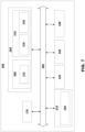
- FIG. 7 is a schematic diagram of a computer system 300 for implementing examples disclosed herein.
- the computer system 300 is adapted to execute instructions from a computer-readable medium to perform these and/or any of the functions or processing described herein.
- the computer system 300 may be connected (e.g., networked) to other machines in a LAN, an intranet, an extranet, or the Internet. While only a single device is illustrated, the computer system 300 may include any collection of devices that individually or jointly execute a set (or multiple sets) of instructions to perform any one or more of the methodologies discussed herein.
- any reference in the disclosure and/or claims to a computer system, computing system, computer device, computing device, control system, control unit, electronic control unit (ECU), processor device, processing circuitry, etc. includes reference to one or more such devices to individually or jointly execute a set (or multiple sets) of instructions to perform any one or more of the methodologies discussed herein.
- control system may include a single control unit or a plurality of control units connected or otherwise communicatively coupled to each other, such that any performed function may be distributed between the control units as desired.
- such devices may communicate with each other or other devices by various system architectures, such as directly or via a Controller Area Network (CAN) bus, etc.
- CAN Controller Area Network
- the computer system 300 may comprise at least one computing device or electronic device capable of including firmware, hardware, and/or executing software instructions to implement the functionality described herein.
- the computer system 300 may include processing circuitry 110 (e.g., processing circuitry including one or more processor devices or control units), a memory 304, and a system bus 306.
- the computer system 300 may include at least one computing device having the processing circuitry 110.
- the system bus 306 provides an interface for system components including, but not limited to, the memory 304 and the processing circuitry 110.
- the processing circuitry 110 may include any number of hardware components for conducting data or signal processing or for executing computer code stored in memory 304.
- the processing circuitry 110 may, for example, include a general-purpose processor, an application specific processor, a Digital Signal Processor (DSP), an Application Specific Integrated Circuit (ASIC), a Field Programmable Gate Array (FPGA), a circuit containing processing components, a group of distributed processing components, a group of distributed computers configured for processing, or other programmable logic device, discrete gate or transistor logic, discrete hardware components, or any combination thereof designed to perform the functions described herein.
- the processing circuitry 110 may further include computer executable code that controls operation of the programmable device.
- the system bus 306 may be any of several types of bus structures that may further interconnect to a memory bus (with or without a memory controller), a peripheral bus, and/or a local bus using any of a variety of bus architectures.
- the memory 304 may be one or more devices for storing data and/or computer code for completing or facilitating methods described herein.
- the memory 304 may include database components, object code components, script components, or other types of information structure for supporting the various activities herein. Any distributed or local memory device may be utilized with the systems and methods of this description.
- the memory 304 may be communicably connected to the processing circuitry 110 (e.g., via a circuit or any other wired, wireless, or network connection) and may include computer code for executing one or more processes described herein.
- the memory 304 may include non-volatile memory 308 (e.g., read-only memory (ROM), erasable programmable read-only memory (EPROM), electrically erasable programmable read-only memory (EEPROM), etc.), and volatile memory 310 (e.g., random-access memory (RAM)), or any other medium which can be used to carry or store desired program code in the form of machine-executable instructions or data structures and which can be accessed by a computer or other machine with processing circuitry 110.
- a basic input/output system (BIOS) 312 may be stored in the non-volatile memory 308 and can include the basic routines that help to transfer information between elements within the computer system 300.
- Computer-code which is hard or soft coded may be provided in the form of one or more modules.
- the module(s) can be implemented as software and/or hard-coded in circuitry to implement the functionality described herein in whole or in part.
- the modules may be stored in the storage device 314 and/or in the volatile memory 310, which may include an operating system 316 and/or one or more program modules 318. All or a portion of the examples disclosed herein may be implemented as a computer program 320 stored on a transitory or non-transitory computer-usable or computer-readable storage medium (e.g., single medium or multiple media), such as the storage device 314, which includes complex programming instructions (e.g., complex computer-readable program code) to cause the processing circuitry 110 to carry out actions described herein.
- complex programming instructions e.g., complex computer-readable program code
- the computer-readable program code of the computer program 320 can comprise software instructions for implementing the functionality of the examples described herein when executed by the processing circuitry 110.
- the storage device 314 may be a computer program product (e.g., readable storage medium) storing the computer program 320 thereon, where at least a portion of a computer program 320 may be loadable (e.g., into a processor) for implementing the functionality of the examples described herein when executed by the processing circuitry 110.
- the processing circuitry 110 may serve as a controller or control system for the computer system 300 that is to implement the functionality described herein.
- the computer system 300 may include an input device interface 322 configured to receive input and selections to be communicated to the computer system 300 when executing instructions, such as from a keyboard, mouse, touch-sensitive surface, etc. Such input devices may be connected to the processing circuitry 110 through the input device interface 322 coupled to the system bus 306 but can be connected through other interfaces, such as a parallel port, an Institute of Electrical and Electronic Engineers (IEEE) 1394 serial port, a Universal Serial Bus (USB) port, an IR interface, and the like.
- the computer system 300 may include an output device interface 324 configured to forward output, such as to a display, a video display unit (e.g., a liquid crystal display (LCD) or a cathode ray tube (CRT)).
- the computer system 300 may include a communications interface 326 suitable for communicating with a network as appropriate or desired.
- Relative terms such as “below” or “above” or “upper” or “lower” or “horizontal” or “vertical” may be used herein to describe a relationship of one element to another element as illustrated in the Figures. It will be understood that these terms and those discussed above are intended to encompass different orientations of the device in addition to the orientation depicted in the Figures. It will be understood that when an element is referred to as being “connected” or “coupled” to another element, it can be directly connected or coupled to the other element, or intervening elements may be present. In contrast, when an element is referred to as being “directly connected” or “directly coupled” to another element, there are no intervening elements present.
Landscapes
- Engineering & Computer Science (AREA)
- Chemical & Material Sciences (AREA)
- Combustion & Propulsion (AREA)
- Transportation (AREA)
- Mechanical Engineering (AREA)
- Steering Control In Accordance With Driving Conditions (AREA)
Claims (15)
- Hydraulisches Lenksystem (100), umfassend eine Lenkeingangseinheit, SIU, (120) und eine Verarbeitungsschaltung (110), die konfiguriert ist, um eine von der SIU (120) ausgeübte haptische Rückmeldung zu steuern, dadurch gekennzeichnet, dass die Verarbeitungsschaltung (110) zu Folgendem konfiguriert ist:Erlangen einer verfügbaren hydraulischen Lenkkapazität (115) des hydraulischen Lenksystems (100), undSteuern der haptischen Rückmeldung, die auf die SIU (120) ausgeübt wird, basierend auf der erlangten hydraulischen Lenkkapazität (115).
- Hydraulisches Lenksystem (100) nach Anspruch 1, wobei das Erlangen der verfügbaren hydraulischen Lenkkapazität (115) Folgendes umfasst:Erlangen von hydraulischen Betriebsdaten (112) des hydraulischen Lenksystems (100), undBestimmen der verfügbaren hydraulischen Lenkkapazität (115) basierend auf den hydraulischen Betriebsdaten (112).
- Hydraulisches Lenksystem (100) nach Anspruch 2, wobei die hydraulischen Betriebsdaten (112) eine aktuelle hydraulische Leistung des hydraulischen Lenksystems (100) umfassen.
- Hydraulisches Lenksystem (100) nach Anspruch 2 oder 3, wobei die hydraulischen Betriebsdaten (112) einen aktuellen Hydraulikfluss des hydraulischen Lenksystems (100) umfassen.
- Hydraulisches Lenksystem (100) nach einem der Ansprüche 2 bis 4, wobei die hydraulischen Betriebsdaten (112) eine aktuelle Drehzahl einer Hydraulikpumpe (130) umfassen, die das hydraulische Lenksystem (100) antreibt.
- Hydraulisches Lenksystem (100) nach einem der vorherigen Ansprüche, wobei das hydraulische Lenksystem (100) ein Steer-by-Wire-System (SBW) ist.
- Hydraulisches Lenksystem (100) nach einem der vorherigen Ansprüche, wobei ein Steuern der haptischen Rückmeldung ein Steuern eines Drehmoments umfasst, das auf die SIU (120) ausgeübt wird.
- Hydraulisches Lenksystem (100) nach einem der vorherigen Ansprüche, wobei die Verarbeitungsschaltung (110) ferner konfiguriert ist, um Umgebungsdaten (117) zu erlangen und die auf die SIU (120) ausgeübte haptische Rückmeldung auch basierend auf den Umgebungsdaten (117) zu steuern, wobei die Umgebungsdaten (117) eines oder mehrere von einem Straßenzustand, einer Wetterbedingung und/oder Topologiedaten umfassen.
- Fahrzeug (10), umfassend ein hydraulisches Lenksystem (100), umfassend eine Lenkeingangseinheit, SIU, (120) und eine Verarbeitungsschaltung (110), die konfiguriert ist, um eine von der SIU (120) ausgeübte haptische Rückmeldung zu steuern, dadurch gekennzeichnet, dass die Verarbeitungsschaltung zu Folgendem konfiguriert ist:Erlangen einer verfügbaren hydraulischen Lenkkapazität (115) des Fahrzeugs (10), undSteuern der haptischen Rückmeldung, die auf die SIU (120) ausgeübt wird, basierend auf der erlangten hydraulischen Lenkkapazität (115).
- Fahrzeug (10) nach Anspruch 9, wobei das hydraulische Lenksystem (100) das hydraulische Lenksystem (100) nach einem der Ansprüche 2 bis 8 ist.
- Fahrzeug (10) nach Anspruch 9 oder 10, wobei das hydraulische Lenksystem (100) mindestens eine Hydraulikpumpe (130) umfasst, die angeordnet ist, um von einer Antriebsquelle (12) des Fahrzeugs (10) angetrieben zu werden; wobei mindestens eine Hydraulikpumpe (130) proportional zu einer Fahrgeschwindigkeit des Fahrzeugs (10) angetrieben wird und die hydraulischen Betriebsdaten (112) eine aktuelle Fahrgeschwindigkeit des Fahrzeugs (10) umfassen, und/oder mindestens eine Hydraulikpumpe (130) proportional zu einer Drehgeschwindigkeit der Antriebsquelle (12) angetrieben wird und die hydraulischen Betriebsdaten (112) eine aktuelle Drehgeschwindigkeit der Antriebsquelle (12) umfassen.
- Fahrzeug (10) nach einem der Ansprüche 9 bis 11, wobei das Fahrzeug ein Gelenkfahrzeug ist.
- Verfahren (200) zum Bestimmen einer haptischen Rückmeldung, die von einer Lenkeingangseinheit, SIU, (120) eines hydraulischen Lenksystems (100) ausgeübt wird, das Verfahren (200) umfassend:Erlangen (230) einer verfügbaren hydraulischen Lenkkapazität (115) des Fahrzeugs (10), undSteuern (240) der haptischen Rückmeldung, die auf die SIU (120) ausgeübt wird, basierend auf der erlangten hydraulischen Lenkkapazität (115).
- Verfahren (200) nach Anspruch 13, wobei das Erlangen der verfügbaren hydraulischen Lenkkapazität (115) Folgendes umfasst:Erlangen (210) von hydraulischen Betriebsdaten (112) des hydraulischen Lenksystems (100), undBestimmen (220) der verfügbaren hydraulischen Lenkkapazität (115) basierend auf den hydraulischen Betriebsdaten (112).
- Verfahren nach Anspruch 14, wobei die hydraulischen Betriebsdaten (112) mindestens eines von einer aktuellen hydraulischen Leistung des hydraulischen Lenksystems (100), einem aktuellen hydraulischen Durchfluss des hydraulischen Lenksystems (100) und/oder einer aktuellen Drehzahl einer Hydraulikpumpe (130), die das hydraulische Lenksystem (100) antreibt, umfasst.
Priority Applications (3)
| Application Number | Priority Date | Filing Date | Title |
|---|---|---|---|
| EP23162286.1A EP4431366B1 (de) | 2023-03-16 | 2023-03-16 | Rückkopplungssteuerung |
| CN202410177156.0A CN118665581A (zh) | 2023-03-16 | 2024-02-08 | 反馈控制 |
| US18/441,641 US12441397B2 (en) | 2023-03-16 | 2024-02-14 | Feedback control |
Applications Claiming Priority (1)
| Application Number | Priority Date | Filing Date | Title |
|---|---|---|---|
| EP23162286.1A EP4431366B1 (de) | 2023-03-16 | 2023-03-16 | Rückkopplungssteuerung |
Publications (2)
| Publication Number | Publication Date |
|---|---|
| EP4431366A1 EP4431366A1 (de) | 2024-09-18 |
| EP4431366B1 true EP4431366B1 (de) | 2025-06-25 |
Family
ID=85704027
Family Applications (1)
| Application Number | Title | Priority Date | Filing Date |
|---|---|---|---|
| EP23162286.1A Active EP4431366B1 (de) | 2023-03-16 | 2023-03-16 | Rückkopplungssteuerung |
Country Status (3)
| Country | Link |
|---|---|
| US (1) | US12441397B2 (de) |
| EP (1) | EP4431366B1 (de) |
| CN (1) | CN118665581A (de) |
Family Cites Families (12)
| Publication number | Priority date | Publication date | Assignee | Title |
|---|---|---|---|---|
| DE19650475C1 (de) * | 1996-12-05 | 1998-04-16 | Daimler Benz Ag | Fahrzeuglenkung |
| JP3827844B2 (ja) * | 1997-12-19 | 2006-09-27 | 株式会社小松製作所 | 建設機械の制御方法および制御装置 |
| JP3875209B2 (ja) * | 2003-04-22 | 2007-01-31 | 株式会社ジェイテクト | ステアバイワイヤシステム及びその制御プログラム |
| JP4446822B2 (ja) * | 2004-07-13 | 2010-04-07 | 日立建機株式会社 | 作業車両の油圧駆動装置 |
| JP4270505B2 (ja) * | 2004-08-11 | 2009-06-03 | 株式会社小松製作所 | 作業車両のエンジンの負荷制御装置 |
| DE102010039509A1 (de) * | 2010-08-19 | 2012-02-23 | Deere & Company | Hydraulische Anordnung |
| US9050999B2 (en) | 2013-01-25 | 2015-06-09 | Caterpillar Inc | System with smart steering force feedback |
| US20140343697A1 (en) | 2013-05-17 | 2014-11-20 | Caterpillar Inc. | Selectable Operating Modes for Machine Operator Input Devices |
| US11167791B2 (en) | 2016-05-31 | 2021-11-09 | Komatsu Ltd. | Work vehicle and method for controlling work vehicle |
| EP3486140B1 (de) | 2017-11-20 | 2021-01-20 | Steering Solutions IP Holding Corporation | Sichtbasiertes aktives lenksystem |
| IT201900010539A1 (it) * | 2019-07-01 | 2021-01-01 | Ognibene Power Spa | Gruppo di sterzatura idrostatico |
| CN116443097A (zh) * | 2023-04-20 | 2023-07-18 | 浙江吉利控股集团有限公司 | 液压转向系统的控制方法、液压转向系统及可读存储介质 |
-
2023
- 2023-03-16 EP EP23162286.1A patent/EP4431366B1/de active Active
-
2024
- 2024-02-08 CN CN202410177156.0A patent/CN118665581A/zh active Pending
- 2024-02-14 US US18/441,641 patent/US12441397B2/en active Active
Also Published As
| Publication number | Publication date |
|---|---|
| US20240308578A1 (en) | 2024-09-19 |
| EP4431366A1 (de) | 2024-09-18 |
| US12441397B2 (en) | 2025-10-14 |
| CN118665581A (zh) | 2024-09-20 |
Similar Documents
| Publication | Publication Date | Title |
|---|---|---|
| US9522697B2 (en) | Control method for electrohydraulic power steering system | |
| CN103429875B (zh) | 作业车辆的驱动控制装置 | |
| CN107792168A (zh) | 一种套筒电机线控转向装置及控制方法 | |
| CN103958904B (zh) | 基于温度控制液压系统的系统和方法 | |
| JP6434128B2 (ja) | ハイブリッド式作業車両 | |
| US20090025661A1 (en) | Cooling fan drive system for travel type working machine | |
| US10106192B2 (en) | Method for teaching permissible steering angles in a steering device of a motor vehicle | |
| EP3372734B1 (de) | System und verfahren zur reduzierung des kraftstoffverbrauchs eines arbeitsfahrzeugs | |
| CN107963118B (zh) | 马达驱动动力转向系统的控制方法 | |
| JP4485802B2 (ja) | 油圧式サーボ操舵装置 | |
| SE525774C2 (sv) | Förfarande, anordning samt datorprogramprodukt för styrning av ett fordon | |
| US20170241542A1 (en) | Control module | |
| CN207523780U (zh) | 一种汽车线控转向执行机构及汽车转向装置 | |
| EP4431366B1 (de) | Rückkopplungssteuerung | |
| US10011173B2 (en) | Powertrain system for maintaining rimpull performance of machine | |
| JP2008505795A (ja) | 油圧式パワーステアリング及びステアリングトルクを算定する方法 | |
| EP4180305B1 (de) | Schätzung des hydraulikflusses in einem lenksystem eines gelenkfahrzeugs | |
| CN109466629A (zh) | 确定动力转向系统的辅助转矩的方法 | |
| SE534530C2 (sv) | Hastighetsstyrning hos en motor och drivkraftöverföring | |
| US20090127018A1 (en) | Component combination for a hydrostatically driven vehicle | |
| US20190270480A1 (en) | Apparatus and method for turning steerable vehicle wheels | |
| EP1697201B1 (de) | Verfahren und rechnerprodukt in einer lenkanordnung für ein fahrzeug | |
| US20240208569A1 (en) | Method for changing a steering angle of a steered wheel of a vehicle | |
| CN206926718U (zh) | 一种电液混合式无人驾驶汽车转向系统 | |
| EP4682023A1 (de) | Servolenksystem |
Legal Events
| Date | Code | Title | Description |
|---|---|---|---|
| PUAI | Public reference made under article 153(3) epc to a published international application that has entered the european phase |
Free format text: ORIGINAL CODE: 0009012 |
|
| STAA | Information on the status of an ep patent application or granted ep patent |
Free format text: STATUS: THE APPLICATION HAS BEEN PUBLISHED |
|
| AK | Designated contracting states |
Kind code of ref document: A1 Designated state(s): AL AT BE BG CH CY CZ DE DK EE ES FI FR GB GR HR HU IE IS IT LI LT LU LV MC ME MK MT NL NO PL PT RO RS SE SI SK SM TR |
|
| STAA | Information on the status of an ep patent application or granted ep patent |
Free format text: STATUS: REQUEST FOR EXAMINATION WAS MADE |
|
| 17P | Request for examination filed |
Effective date: 20240926 |
|
| RBV | Designated contracting states (corrected) |
Designated state(s): AL AT BE BG CH CY CZ DE DK EE ES FI FR GB GR HR HU IE IS IT LI LT LU LV MC ME MK MT NL NO PL PT RO RS SE SI SK SM TR |
|
| GRAP | Despatch of communication of intention to grant a patent |
Free format text: ORIGINAL CODE: EPIDOSNIGR1 |
|
| STAA | Information on the status of an ep patent application or granted ep patent |
Free format text: STATUS: GRANT OF PATENT IS INTENDED |
|
| INTG | Intention to grant announced |
Effective date: 20250210 |
|
| GRAS | Grant fee paid |
Free format text: ORIGINAL CODE: EPIDOSNIGR3 |
|
| GRAA | (expected) grant |
Free format text: ORIGINAL CODE: 0009210 |
|
| STAA | Information on the status of an ep patent application or granted ep patent |
Free format text: STATUS: THE PATENT HAS BEEN GRANTED |
|
| AK | Designated contracting states |
Kind code of ref document: B1 Designated state(s): AL AT BE BG CH CY CZ DE DK EE ES FI FR GB GR HR HU IE IS IT LI LT LU LV MC ME MK MT NL NO PL PT RO RS SE SI SK SM TR |
|
| REG | Reference to a national code |
Ref country code: GB Ref legal event code: FG4D |
|
| REG | Reference to a national code |
Ref country code: CH Ref legal event code: EP |
|
| REG | Reference to a national code |
Ref country code: CH Ref legal event code: EP |
|
| REG | Reference to a national code |
Ref country code: IE Ref legal event code: FG4D |
|
| REG | Reference to a national code |
Ref country code: DE Ref legal event code: R096 Ref document number: 602023004186 Country of ref document: DE |
|
| PG25 | Lapsed in a contracting state [announced via postgrant information from national office to epo] |
Ref country code: FI Free format text: LAPSE BECAUSE OF FAILURE TO SUBMIT A TRANSLATION OF THE DESCRIPTION OR TO PAY THE FEE WITHIN THE PRESCRIBED TIME-LIMIT Effective date: 20250625 |
|
| REG | Reference to a national code |
Ref country code: LT Ref legal event code: MG9D |
|
| PG25 | Lapsed in a contracting state [announced via postgrant information from national office to epo] |
Ref country code: NO Free format text: LAPSE BECAUSE OF FAILURE TO SUBMIT A TRANSLATION OF THE DESCRIPTION OR TO PAY THE FEE WITHIN THE PRESCRIBED TIME-LIMIT Effective date: 20250925 Ref country code: GR Free format text: LAPSE BECAUSE OF FAILURE TO SUBMIT A TRANSLATION OF THE DESCRIPTION OR TO PAY THE FEE WITHIN THE PRESCRIBED TIME-LIMIT Effective date: 20250926 |
|
| PG25 | Lapsed in a contracting state [announced via postgrant information from national office to epo] |
Ref country code: BG Free format text: LAPSE BECAUSE OF FAILURE TO SUBMIT A TRANSLATION OF THE DESCRIPTION OR TO PAY THE FEE WITHIN THE PRESCRIBED TIME-LIMIT Effective date: 20250625 |
|
| PG25 | Lapsed in a contracting state [announced via postgrant information from national office to epo] |
Ref country code: HR Free format text: LAPSE BECAUSE OF FAILURE TO SUBMIT A TRANSLATION OF THE DESCRIPTION OR TO PAY THE FEE WITHIN THE PRESCRIBED TIME-LIMIT Effective date: 20250625 |
|
| PG25 | Lapsed in a contracting state [announced via postgrant information from national office to epo] |
Ref country code: RS Free format text: LAPSE BECAUSE OF FAILURE TO SUBMIT A TRANSLATION OF THE DESCRIPTION OR TO PAY THE FEE WITHIN THE PRESCRIBED TIME-LIMIT Effective date: 20250925 |
|
| PG25 | Lapsed in a contracting state [announced via postgrant information from national office to epo] |
Ref country code: LV Free format text: LAPSE BECAUSE OF FAILURE TO SUBMIT A TRANSLATION OF THE DESCRIPTION OR TO PAY THE FEE WITHIN THE PRESCRIBED TIME-LIMIT Effective date: 20250625 |
|
| REG | Reference to a national code |
Ref country code: NL Ref legal event code: MP Effective date: 20250625 |
|
| PG25 | Lapsed in a contracting state [announced via postgrant information from national office to epo] |
Ref country code: NL Free format text: LAPSE BECAUSE OF FAILURE TO SUBMIT A TRANSLATION OF THE DESCRIPTION OR TO PAY THE FEE WITHIN THE PRESCRIBED TIME-LIMIT Effective date: 20250625 |
|
| PG25 | Lapsed in a contracting state [announced via postgrant information from national office to epo] |
Ref country code: PT Free format text: LAPSE BECAUSE OF FAILURE TO SUBMIT A TRANSLATION OF THE DESCRIPTION OR TO PAY THE FEE WITHIN THE PRESCRIBED TIME-LIMIT Effective date: 20251027 |
|
| REG | Reference to a national code |
Ref country code: AT Ref legal event code: MK05 Ref document number: 1806199 Country of ref document: AT Kind code of ref document: T Effective date: 20250625 |
|
| PG25 | Lapsed in a contracting state [announced via postgrant information from national office to epo] |
Ref country code: IS Free format text: LAPSE BECAUSE OF FAILURE TO SUBMIT A TRANSLATION OF THE DESCRIPTION OR TO PAY THE FEE WITHIN THE PRESCRIBED TIME-LIMIT Effective date: 20251025 |
|
| PG25 | Lapsed in a contracting state [announced via postgrant information from national office to epo] |
Ref country code: AT Free format text: LAPSE BECAUSE OF FAILURE TO SUBMIT A TRANSLATION OF THE DESCRIPTION OR TO PAY THE FEE WITHIN THE PRESCRIBED TIME-LIMIT Effective date: 20250625 Ref country code: SM Free format text: LAPSE BECAUSE OF FAILURE TO SUBMIT A TRANSLATION OF THE DESCRIPTION OR TO PAY THE FEE WITHIN THE PRESCRIBED TIME-LIMIT Effective date: 20250625 |
|
| PG25 | Lapsed in a contracting state [announced via postgrant information from national office to epo] |
Ref country code: CZ Free format text: LAPSE BECAUSE OF FAILURE TO SUBMIT A TRANSLATION OF THE DESCRIPTION OR TO PAY THE FEE WITHIN THE PRESCRIBED TIME-LIMIT Effective date: 20250625 |
|
| PG25 | Lapsed in a contracting state [announced via postgrant information from national office to epo] |
Ref country code: PL Free format text: LAPSE BECAUSE OF FAILURE TO SUBMIT A TRANSLATION OF THE DESCRIPTION OR TO PAY THE FEE WITHIN THE PRESCRIBED TIME-LIMIT Effective date: 20250625 |
|
| PG25 | Lapsed in a contracting state [announced via postgrant information from national office to epo] |
Ref country code: EE Free format text: LAPSE BECAUSE OF FAILURE TO SUBMIT A TRANSLATION OF THE DESCRIPTION OR TO PAY THE FEE WITHIN THE PRESCRIBED TIME-LIMIT Effective date: 20250625 |
|
| PG25 | Lapsed in a contracting state [announced via postgrant information from national office to epo] |
Ref country code: SK Free format text: LAPSE BECAUSE OF FAILURE TO SUBMIT A TRANSLATION OF THE DESCRIPTION OR TO PAY THE FEE WITHIN THE PRESCRIBED TIME-LIMIT Effective date: 20250625 |
|
| PG25 | Lapsed in a contracting state [announced via postgrant information from national office to epo] |
Ref country code: ES Free format text: LAPSE BECAUSE OF FAILURE TO SUBMIT A TRANSLATION OF THE DESCRIPTION OR TO PAY THE FEE WITHIN THE PRESCRIBED TIME-LIMIT Effective date: 20250625 |
|
| PG25 | Lapsed in a contracting state [announced via postgrant information from national office to epo] |
Ref country code: DK Free format text: LAPSE BECAUSE OF FAILURE TO SUBMIT A TRANSLATION OF THE DESCRIPTION OR TO PAY THE FEE WITHIN THE PRESCRIBED TIME-LIMIT Effective date: 20250625 |
|
| PGFP | Annual fee paid to national office [announced via postgrant information from national office to epo] |
Ref country code: DE Payment date: 20260320 Year of fee payment: 4 |
|
| PG25 | Lapsed in a contracting state [announced via postgrant information from national office to epo] |
Ref country code: IT Free format text: LAPSE BECAUSE OF FAILURE TO SUBMIT A TRANSLATION OF THE DESCRIPTION OR TO PAY THE FEE WITHIN THE PRESCRIBED TIME-LIMIT Effective date: 20250625 |
|
| PLBE | No opposition filed within time limit |
Free format text: ORIGINAL CODE: 0009261 |
|
| STAA | Information on the status of an ep patent application or granted ep patent |
Free format text: STATUS: NO OPPOSITION FILED WITHIN TIME LIMIT |