EP4430596B1 - Elektronische musiktastatur - Google Patents
Elektronische musiktastatur Download PDFInfo
- Publication number
- EP4430596B1 EP4430596B1 EP22799992.7A EP22799992A EP4430596B1 EP 4430596 B1 EP4430596 B1 EP 4430596B1 EP 22799992 A EP22799992 A EP 22799992A EP 4430596 B1 EP4430596 B1 EP 4430596B1
- Authority
- EP
- European Patent Office
- Prior art keywords
- key
- keyboard
- sound
- microcontroller
- electronic music
- Prior art date
- Legal status (The legal status is an assumption and is not a legal conclusion. Google has not performed a legal analysis and makes no representation as to the accuracy of the status listed.)
- Active
Links
Images


Classifications
-
- G—PHYSICS
- G10—MUSICAL INSTRUMENTS; ACOUSTICS
- G10H—ELECTROPHONIC MUSICAL INSTRUMENTS; INSTRUMENTS IN WHICH THE TONES ARE GENERATED BY ELECTROMECHANICAL MEANS OR ELECTRONIC GENERATORS, OR IN WHICH THE TONES ARE SYNTHESISED FROM A DATA STORE
- G10H1/00—Details of electrophonic musical instruments
- G10H1/18—Selecting circuits
- G10H1/183—Channel-assigning means for polyphonic instruments
- G10H1/185—Channel-assigning means for polyphonic instruments associated with key multiplexing
- G10H1/186—Microprocessor-controlled keyboard and assigning means
-
- G—PHYSICS
- G10—MUSICAL INSTRUMENTS; ACOUSTICS
- G10H—ELECTROPHONIC MUSICAL INSTRUMENTS; INSTRUMENTS IN WHICH THE TONES ARE GENERATED BY ELECTROMECHANICAL MEANS OR ELECTRONIC GENERATORS, OR IN WHICH THE TONES ARE SYNTHESISED FROM A DATA STORE
- G10H1/00—Details of electrophonic musical instruments
- G10H1/0008—Associated control or indicating means
-
- G—PHYSICS
- G10—MUSICAL INSTRUMENTS; ACOUSTICS
- G10H—ELECTROPHONIC MUSICAL INSTRUMENTS; INSTRUMENTS IN WHICH THE TONES ARE GENERATED BY ELECTROMECHANICAL MEANS OR ELECTRONIC GENERATORS, OR IN WHICH THE TONES ARE SYNTHESISED FROM A DATA STORE
- G10H1/00—Details of electrophonic musical instruments
- G10H1/02—Means for controlling the tone frequencies, e.g. attack or decay; Means for producing special musical effects, e.g. vibratos or glissandos
- G10H1/04—Means for controlling the tone frequencies, e.g. attack or decay; Means for producing special musical effects, e.g. vibratos or glissandos by additional modulation
- G10H1/053—Means for controlling the tone frequencies, e.g. attack or decay; Means for producing special musical effects, e.g. vibratos or glissandos by additional modulation during execution only
- G10H1/055—Means for controlling the tone frequencies, e.g. attack or decay; Means for producing special musical effects, e.g. vibratos or glissandos by additional modulation during execution only by switches with variable impedance elements
- G10H1/0555—Means for controlling the tone frequencies, e.g. attack or decay; Means for producing special musical effects, e.g. vibratos or glissandos by additional modulation during execution only by switches with variable impedance elements using magnetic or electromagnetic means
-
- G—PHYSICS
- G10—MUSICAL INSTRUMENTS; ACOUSTICS
- G10H—ELECTROPHONIC MUSICAL INSTRUMENTS; INSTRUMENTS IN WHICH THE TONES ARE GENERATED BY ELECTROMECHANICAL MEANS OR ELECTRONIC GENERATORS, OR IN WHICH THE TONES ARE SYNTHESISED FROM A DATA STORE
- G10H1/00—Details of electrophonic musical instruments
- G10H1/02—Means for controlling the tone frequencies, e.g. attack or decay; Means for producing special musical effects, e.g. vibratos or glissandos
- G10H1/06—Circuits for establishing the harmonic content of tones, or other arrangements for changing the tone colour
- G10H1/14—Circuits for establishing the harmonic content of tones, or other arrangements for changing the tone colour during execution
-
- G—PHYSICS
- G10—MUSICAL INSTRUMENTS; ACOUSTICS
- G10H—ELECTROPHONIC MUSICAL INSTRUMENTS; INSTRUMENTS IN WHICH THE TONES ARE GENERATED BY ELECTROMECHANICAL MEANS OR ELECTRONIC GENERATORS, OR IN WHICH THE TONES ARE SYNTHESISED FROM A DATA STORE
- G10H1/00—Details of electrophonic musical instruments
- G10H1/32—Constructional details
- G10H1/34—Switch arrangements, e.g. keyboards or mechanical switches specially adapted for electrophonic musical instruments
- G10H1/344—Structural association with individual keys
-
- G—PHYSICS
- G10—MUSICAL INSTRUMENTS; ACOUSTICS
- G10H—ELECTROPHONIC MUSICAL INSTRUMENTS; INSTRUMENTS IN WHICH THE TONES ARE GENERATED BY ELECTROMECHANICAL MEANS OR ELECTRONIC GENERATORS, OR IN WHICH THE TONES ARE SYNTHESISED FROM A DATA STORE
- G10H2220/00—Input/output interfacing specifically adapted for electrophonic musical tools or instruments
- G10H2220/155—User input interfaces for electrophonic musical instruments
- G10H2220/221—Keyboards, i.e. configuration of several keys or key-like input devices relative to one another
-
- G—PHYSICS
- G10—MUSICAL INSTRUMENTS; ACOUSTICS
- G10H—ELECTROPHONIC MUSICAL INSTRUMENTS; INSTRUMENTS IN WHICH THE TONES ARE GENERATED BY ELECTROMECHANICAL MEANS OR ELECTRONIC GENERATORS, OR IN WHICH THE TONES ARE SYNTHESISED FROM A DATA STORE
- G10H2220/00—Input/output interfacing specifically adapted for electrophonic musical tools or instruments
- G10H2220/155—User input interfaces for electrophonic musical instruments
- G10H2220/265—Key design details; Special characteristics of individual keys of a keyboard; Key-like musical input devices, e.g. finger sensors, pedals, potentiometers, selectors
- G10H2220/271—Velocity sensing for individual keys, e.g. by placing sensors at different points along the kinematic path for individual key velocity estimation by delay measurement between adjacent sensor signals
-
- G—PHYSICS
- G10—MUSICAL INSTRUMENTS; ACOUSTICS
- G10H—ELECTROPHONIC MUSICAL INSTRUMENTS; INSTRUMENTS IN WHICH THE TONES ARE GENERATED BY ELECTROMECHANICAL MEANS OR ELECTRONIC GENERATORS, OR IN WHICH THE TONES ARE SYNTHESISED FROM A DATA STORE
- G10H2220/00—Input/output interfacing specifically adapted for electrophonic musical tools or instruments
- G10H2220/155—User input interfaces for electrophonic musical instruments
- G10H2220/265—Key design details; Special characteristics of individual keys of a keyboard; Key-like musical input devices, e.g. finger sensors, pedals, potentiometers, selectors
- G10H2220/275—Switching mechanism or sensor details of individual keys, e.g. details of key contacts, hall effect or piezoelectric sensors used for key position or movement sensing purposes; Mounting thereof
-
- G—PHYSICS
- G10—MUSICAL INSTRUMENTS; ACOUSTICS
- G10H—ELECTROPHONIC MUSICAL INSTRUMENTS; INSTRUMENTS IN WHICH THE TONES ARE GENERATED BY ELECTROMECHANICAL MEANS OR ELECTRONIC GENERATORS, OR IN WHICH THE TONES ARE SYNTHESISED FROM A DATA STORE
- G10H2220/00—Input/output interfacing specifically adapted for electrophonic musical tools or instruments
- G10H2220/461—Transducers, i.e. details, positioning or use of assemblies to detect and convert mechanical vibrations or mechanical strains into an electrical signal, e.g. audio, trigger or control signal
- G10H2220/521—Hall effect transducers or similar magnetic field sensing semiconductor devices, e.g. for string vibration sensing or key movement sensing
Definitions
- the present invention relates to the field of electronic music instruments, and particularly to an electronic music keyboard.
- any electronic music instruments provided with a keyboard it is necessary to determine when the action of pressing a key on the keyboard is to be considered valid for the production of an audio signal capable of reproducing the note intended to be played. Having determined the entire mechanically permissible stroke of the key, it is necessary to determine which position of the stroke is to be associated with the generation of the note.
- FIG. 1 Another example of a real music instrument for which the keyboard covered by such a patent is advantageous is the electromechanical organ represented by the well-known Hammond organ in which a series of phonic wheels placed in front of respective pickups generates as many notes.
- the phonic wheels are connected to each key on the keyboard by means of controls called “drawbars". More precisely, 9 phonic wheels are connected to each key by means of 9 drawbars that individually adjust the intensity of each phonic wheel.
- the inventor of the Hammond organ designed a complicated mechanism consisting of 9 switches for switching on the 9 phonic wheels connected to each key. Such a mechanism was supposed to enable the 9 phonic wheels to provide their signal all at the same instant, but this was not possible and therefore the 9 wheels are switched on in a succession determined by constructive mechanics, in a very small time span. During a typical use, it is not so easy to distinguish the temporal succession of the switching on of the phonic wheels, but, just like all defects in real instruments, such a characteristic has become a distinctive feature of this instrument. Again, the possibility of emulating such a behavior will add realism to the electronic simulation.
- switches are placed under each key to detect when the key is pressed.
- the switches consist in conductive rubber bubbles mounted on a printed circuit board (PCB).
- PCB printed circuit board
- the bubbles produce a contact on the PCB.
- the key presses the bubble, which is deformed, touching two conductive graphite pads disposed on the PCB in such a way to activate a contact because of the conductive rubber.
- a single bubble i.e. a single switch, is used when it is simply necessary to establish the note activation event. Such a case (single contact) has now completely disappeared.
- two bubbles are used that are located at different distances and are activated at two different positions of the key stroke, that is to say at two different time moments, considering that the musician presses the key from its rest position to the end stroke position.
- a Hammond organ with phonic wheels it is necessary to know the position of the key instant by instant in order to continuously determine which of the 9 contacts of the phonic wheels are closed or open. Also in such a case, a skilled organist playing an electromechanical Hammond organ, based on the position of the key can control the opening of the 9 contacts of the phonic wheels at will so as to achieve music effects of considerable interest. Moreover, in the real Hammond organ, the opening and closing of the contacts is highly variable key by key, both in terms of the spatial position of the key and the succession of the phonic wheels that are activated.
- JP205092057 discloses an electronic keyboard that uses a Hall sensor-magnet coupling exclusively to detect the velocity of the key. Otherwise said, the sensor detects only two positions of the key to calculate the velocity of the key. Therefore, such a keyboard is not suitable for emulating a sound of a Hammond organ or of a pipe organ sound or finding a solution for the detection of a repeated note in a piano.
- JPH0439695 and JP205092057 relate to an electronic keyboard dedicated to emulating a piano and consider the use of a magnet-sensor coupling as an improvement of the prior art based on two or three contacts made of conductive rubber.
- the purpose of said patents is to measure the velocity of the key as an indirect measure of the impact force of the hammer on the string, which in itself is not an exactly equivalent measure because the impact force may also be dependent on the acceleration imparted by the pianist's hand during the movement of the key.
- the measured velocity is an average velocity in the measurement section between two positions and is not an instantaneous velocity at the end of travel.
- the purpose of the present invention is to eliminate the drawbacks of the prior art by providing an electronic music keyboard that is capable of recognizing the position of each key, instant by instant.
- Another purpose is to provide such an electronic music keyboard capable of emulating the sound of mechanical (pipe organ) and electromechanical (phonic wheel organ) music instruments, in which the sound effect varies according to the position of the key.
- Still another purpose of the present invention is to provide such an electronic music keyboard that is reliable and capable of generating a sound signal as faithful as possible to conventional mechanical instruments and to improve the management of repeated notes on the piano.
- the electronic music keyboard according to the invention uses magnetic flux density sensors to detect the position of each key.
- a magnetic sensor is a magnetic flux density sensor (also known as magnetic induction field).
- Hall sensors are used to produce a linearly variable voltage at the output depending on an applied magnetic field.
- Such sensors are relatively inexpensive, require no mechanical interaction, are long-lasting and wear-free, unlike mechanical switches.
- magnetic sensors are unaffected by the presence of dust, light, and humidity.
- Such sensors are equipped with compensation circuits for changes in sensitivity upon a temperature change.
- a permanent magnet equipped with north and south poles that must be properly located, is inserted under each key of the keyboard and a PCB is that houses a Hall sensor for each key is provided.
- the magnet When the key is pressed, the magnet is moved closer to the sensor, causing the magnetic induction field to increase and the sensor to produce a variable voltage at its output, the value of which is directly and linearly related to the position of the key during its travel.
- a control microcontroller hereafter referred to as a microcontroller, equipped with as many analog/digital acquisition lines as the sensors to be acquired, it is possible to monitor the voltage output from the various sensors placed under the keys in real time and to determine their position at any instant due to the direct proportionality between voltage and magnet position, i.e. its distance from the sensor.
- the keyboard includes:
- the microcontroller scans the signal lines at regular intervals and determines the voltage supplied by each sensor at each scanning instant; the voltage is converted into position of each individual key; the position is communicated by the microcontroller to a music signal generation system, such as a Digital Signal Processor (DSP).
- DSP Digital Signal Processor
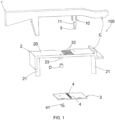
- the keyboard (100) comprises a plurality of keys (1) mounted on a frame (2).
- the keys (1) are hinged to the frame (2) by means of hinges (C).
- Spring means are interposed between the frame (2) and each key (1) to hold the keys in a horizontal position ( Fig. 2 ) when the keys are in rest position.
- the key is tilted downward ( Fig. 3 ) against the action of the spring means.
- the spring means bring the key back to the rest position.
- the keyboard (100) comprises a printed circuit board (PCB) (3) on which a plurality of magnetic sensors (4) equal to the number of keys (1) on the keyboard is mounted.
- Each magnetic sensor (4) can be a Hall sensor.
- the magnetic sensors (4) are aligned along a row.
- a magnet (5) having an effective magnetic pole facing a respective magnetic sensor (4) is mounted in each key (1).
- the second distance (d2) may be small, but the magnet (5) must not contact the magnetic sensor (4) to prevent physical contact from breaking the sensor due to pressure.
- the frame (2) comprises a plate (20) arranged on legs (21) so as to maintain itself along a horizontal plane.
- the PCB (3) is attached to the frame (2) under the plate (20), so that the magnetic sensors (4) of the PCB are in register with the slots (22) of the plate (20).
- Spacers (D) keep the PCB (3) spaced from the plate (20) of the frame.
- the PCB (3) is attached to the plate (20) by means of screw means (41) that are screwed in the spacers (D) and in tangs (23) that protrude inferiorly from the plate (20).
- the keys (1) are mounted above the plate (20) of the frame.
- Each key (1) has a fork (10) that protrudes inferiorly and is suitable for passing through a respective slot (22) of the plate of the frame.
- the holder (11) is suitable for supporting the magnet (5) so that the magnet protrudes inferiorly from the support (11).
- the magnet (5) can have a cylindrical shape.
- the effective pole of the magnet (5) of each key is located under the plate (20) of the frame, near a respective magnetic sensor (4).
- each magnetic sensor (4) generates a voltage signal (V) at the output, which is of analog type, and inversely proportional to the distance between the magnet (5) and the magnetic sensor (4); that is to say, the voltage signal (V) varies from a minimum value when the key (1) is in the rest position, to a maximum value when the key (1) is in the end stroke position.
- the analog voltage signal (V) from each magnetic sensor (4) is continuously digitized by means of a respective analog-to-digital (A/D) converter (6), which generates digital values (V1, .... Vn) of the voltage signal generated by the sensor as an output.
- A/D analog-to-digital
- Each A/D converter (6) is connected to a microcontroller (7) that receives the digital values (V1, .... Vn) of the voltage signal (V) detected by each sensor (4) and converts them into position values indicative of the position of the key.
- A/D converters (6) must be at least 8-bit converters in order to have sufficient resolution of the voltage and consequently of the position for the purposes to be achieved.
- the microcontroller (7) will be able to convert 256 key position values from the rest position to the end stroke position. Therefore, the key positions can be divided into 256 positions from the rest position to the end stroke position
- the microcontroller (7) comprises selection means (70) according to the type of music instrument to be emulated. From among the possible 256 key position values, the selection means (70) select a plurality of useful key positions values (P1, ... Pm) indicative of useful positions of the key (1) in which certain sound signals are to be activated according to the music instrument to be emulated, and thus exclude the other key position values that do not correspond to the useful positions.
- Each useful key position value (P1, ... Pm) is associated with a certain sound signal (S*, S1 ... Sk) according to the instrument to be emulated or an appropriate parameterization of the computational synthesis model of the music signal.
- the microcontroller (7) outputs the corresponding useful key position value (P1, ... Pm) associated with a corresponding sound signal (S*, S1 ... Sk) to be emitted.
- the microcontroller (7) is connected to a digital signal processor (DSP) (8) suitable for modifying a synthesized sound signal (S') according to the useful key position values (P1, ... Pm) sent by the microcontroller (7).
- DSP digital signal processor
- the synthesized sound signal (S') is generated by a synthesis algorithm (of known type and therefore not illustrated) according to the type of instrument to be emulated.
- the DSP (8) modifies the synthesized signal (S') and generates a modified sound signal (S*) that is sent to an electroacoustic transducer (9) that generates a music sound (S).
- the A/D converter (6) of each sensor is controlled by the microcontroller (7) which activates and commands the A/D conversions at regular time intervals. So, with an adequate time resolution, the microcontroller (7) knows the position of the key (1) at each time instant. From among the various positions of the key, ranging from the rest position to the end stroke position, the microcontroller (7) selects some useful key position values (P1, ....Pm) and communicates them to the DSP (8), which modifies the synthesized sound signal (S') and generates the modified sound signal (S*) to be sent to the electroacoustic transducer (9) according to the useful positions selected by the microcontroller.
- P1, ....Pm useful key position values
- the space traveled by the key (1) can be divided into 256 positions from value 0 to value 255.
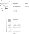
- the DSP (8) is not configured to modify the synthesized sound signal, but it is configured to output nine sound signals (S1, .... S9) of synthesized type for each key of the keyboard, corresponding to the sound of nine phonic wheels of a conventional Hammond organ.
- the microcontroller (7) which controls the A/D converter (6) detects that the useful key positions 1 to 9 have been reached, the microcontroller (7) informs the DSP (8), which will activate an electronic sound that simulates the sound generated by the phonic wheels of a mechanical Hammond organ that would have been activated at that moment.
- the DSP (8) If the musician presses the key downwards, the DSP (8) generates sound signals corresponding to the activated phonic wheels. Otherwise said, when the key reaches position 1, the sound signal (S1) corresponding to the sound of the phonic wheel 1 is activated; when the key reaches position 2, the sound signals (S1, S2) corresponding to the sound of the phonic wheel 1 and of the phonic wheel 2 are activated, and so on until the key reaches position 9, where sound signals (S1, ...S9) corresponding to the sound of all nine phonic wheels are activated. If the key continues to move downwards beyond position 9, the sound signals (S1, ...S9) corresponding to the sound of all nine phonic wheels remain activated.
- the microcontroller (7) informs the DSP (8) of the activation state of the phonic wheels with an appropriate time frequency and based on the information received from the microcontroller (7) the DSP will generate sound signals related to the activated phonic wheels.
- the DSP (8) In order to emulate a pipe organ, the DSP (8) must be configured to modify the synthesized sound signal (S') to simulate different degrees of opening of a pipe organ valve depending on the position of the key.
- the only synthesized signal (S') is modified according to the position of the key.
- the physical generation model of the modified sound can consider the position to modulate the attack noise or to modify the amplitude or to modulate other parameters of the physical model.
- the key positions useful for the sound generation can be taken according to the type of organ pipe to be emulated.
- the DSP (8) is configured to modify the synthesized signal (S') and generate a modified sound signal (S*) according to the pressure exerted on the key.
- the microcontroller (7) can calculate velocity values (I) of the key, such as a total velocity of the key from the rest position (value 0) to the end stroke position (value 255) or a partial velocity of the key from any position to the end stroke position. Since the velocity values (I) of the key are proportional to the pressure exerted on the key, the piece of information on the partial velocity of the key is important in order to simulate what are known as "repeated notes" in an extremely accurate way.
- the velocity values (I) are sent from the microcontroller (7) to the DSP (8) so that the DSP generates sound signals based on the velocity values of the key that are indicative of the pressure exerted on the key, with greater accuracy than the prior art. Due to the linearity of the voltage with respect to the key position, the difference between two consecutive voltage values corresponds to equal distances in the position of the key. Therefore, the measurement time between any two positions corresponds to a correct velocity evaluation.
- the invention also relates to a signal processing method for an electronic music keyboard (100).
- the method comprises the following steps:
Landscapes
- Engineering & Computer Science (AREA)
- Physics & Mathematics (AREA)
- Acoustics & Sound (AREA)
- Multimedia (AREA)
- Computer Hardware Design (AREA)
- Microelectronics & Electronic Packaging (AREA)
- Electromagnetism (AREA)
- Electrophonic Musical Instruments (AREA)
Claims (12)
- Elektronisches Keyboard (100), umfassend:- eine Vielzahl von Tasten (1),- eine Anzahl von Magnetsensoren (4) gleich der Anzahl von Tasten,- einen Dauermagneten (5), der in jeder Taste (1) mit einem Magnetpol angeordnet ist, der einem jeweiligen Magnetsensor (4) zugewandt ist, um sich dem Magnetsensor (4) entsprechend der Bewegung der Taste anzunähern/ davon zu entfernen; wobei der Magnetsensor (4) so konfiguriert ist, dass ein Spannungssignal (V) vom analogen Typ ausgegeben wird, das umgekehrt proportional zum Abstand zwischen dem Magneten (5) und dem Magnetsensor (4) ist,- einen A/D-Wandler (6), der mit jedem Magnetsensor (4) verbunden ist, um das von dem Magnetsensor erzeugte Spannungssignal (V) zu digitalisieren und eine Vielzahl von digitalen Werten (V1, ... Vn) auszugeben, die indikativ für die Tastenposition sind,- einen Mikrocontroller (7), der mit den A/D-Wandlern (6) verbunden und konfiguriert ist, um die digitalen Werte (V1, ... Vn), die indikativ für die Tastenposition sind, zu empfangen und sie in Tastenpositionswerte umzuwandeln;- einen Digitalsignalprozessor (DSP) (8), der mit dem Mikrocontroller (7) verbunden ist, um mindestens ein Tonsignal (S*; S1, ....Sk) zu erzeugen und- einen elektroakustischen Wandler (9), der mit dem DSP (8) verbunden und konfiguriert ist, um das mindestens eine Tonsignal (S*; S1, ....Sk) zu empfangen und dementsprechend einen Musikton (S) zu erzeugen,dadurch gekennzeichnet, dassjeder A/D-Wandler (6) mindestens ein 8-Bit-Wandler ist, der in der Lage ist, mindestens 256 Digitalwerte (V1, ... Vn) bereitzustellen, die indikativ für die Tastenposition sind,der Mikrocontroller (7) konfiguriert ist, um die mindestens 256 Digitalwerte (V1, ... Vn) von jedem A/D-Wandler (6) in jeweilige mindestens 256 Tastenpositionswerte umzuwandeln, die von einer Ruheposition zu einer Endanschlagsposition variieren;der Mikrocontroller (7) Auswahlmittel (70) entsprechend der Art des zu emulierenden Musikinstruments umfasst; die Auswahlmittel (70) so konfiguriert sind, dass sie aus den mindestens 256 Tastenpositionswerten eine Vielzahl von nützlichen Tastenpositionswerten (P1, ...Pm) auswählen, die jeweiligen Tonsignalen (S*, S1...Sk) entsprechend der Art des zu emulierenden Musikinstruments zugeordnet sind;wobei der Mikrocontroller (7) so konfiguriert ist, dass er einen nützlichen Tastenpositionswert (P1, ...Pm) emittiert, der der Tastenposition beim Gebrauch des Keyboards entspricht;wobei der Digitalsignalprozessor (DSP) (8) so konfiguriert ist, dass er den vom Mikrocontroller emittierten nützlichen Tastenpositionswert (Pa, ...Pm) empfängt und dementsprechend das Tonsignal (S*, S1...Sk), das dem nützlichen Wert zugeordnet ist, an den elektroakustischen Wandler (9) emittiert, der den Musikton (S) emittiert.
- Elektronisches Keyboard (100) nach Anspruch 1, wobei der Magnetsensor (4) ein Hallsensor ist.
- Elektronisches Keyboard (100) nach Anspruch 1 oder 2, wobei die Magnetsensoren (4) auf einer Leiterplatte (3) montiert sind, die unter einer Platte (20) eines Gestells (2) angeordnet sind, auf dem die Tasten (1) montiert sind.
- Elektronisches Keyboard (100) nach Anspruch 3, wobei die Magnetsensoren (4) auf der Leiterplatte (3) positioniert sind und in einer Reihe ausgerichtet sind.
- Elektronisches Keyboard (100) nach Anspruch 3, wobei die Platte (20) des Gestells eine Vielzahl von durchgehenden Schlitzen (22) aufweist, die parallel zueinander und in einer Reihe ausgerichtet sind, und die Leiterplatte (3) an dem Gestell (2) unterhalb der Platte (20) so befestigt ist, dass die Magnetsensoren (4) der Leiterplatte sich in Übereinstimmung mit den Schlitzen (22) der Platte (20) befinden.
- Elektronisches Keyboard (100) nach Anspruch 5, wobei jede Taste (1) eine Gabel (10) aufweist, in der eine Halterung (11) montiert ist, um den Magneten (5) zu halten; wobei die Gabel (10) unterseitig aus der Taste so vorsteht, dass sie durch einen jeweiligen Schlitz (22) der Platte des Rahmens hindurchgeht.
- Elektronisches Keyboard (100) nach einem der Ansprüche 3 bis 6, umfassend Distanzstücke (D), die zwischen der Leiterplatte (3) und der Platte (20) des Gestells angeordnet sind, um die Leiterplatte von der Platte des Gestells beabstandet zu halten.
- Elektronisches Keyboard (100) nach einem der vorstehenden Ansprüche, wobei der DSP (8) so konfiguriert ist, dass er für jede Taste des Keyboards neun Tonsignale (S1, ...S9) emittiert, die dem Ton von neun phonischen Rädern einer traditionellen Hammondorgel entsprechen.
- Elektronisches Keyboard (100) nach einem der vorstehenden Ansprüche, wobei der DSP (8) so konfiguriert ist, dass er ein synthetisiertes Tonsignal (S') entsprechend den vom Mikrocontroller (7) gesendeten nützlichen Tastenspositionswerten (P1, ... Pm) modifiziert und ein modifiziertes Tonsignal (S*) erzeugt, das an den elektroakustischen Wandler (9) gesendet wird.
- Elektronisches Keyboard (100) nach Anspruch 9, wobei das synthetisierte Tonsignal (S') das Tonsignal einer Pfeifenorgel ist, das entsprechend unterschiedlichen Öffnungsgraden eines Ventils einer Pfeifenorgel auf der Grundlage der Position einer jeden Taste modifiziert wird.
- Elektronisches Keyboard 100) nach einem der vorstehenden Ansprüche, wobeider Mikrocontroller (7) so konfiguriert ist, dass er Tastengeschwindigkeitswerte (I) als den von der Taste zwischen zwei Tastenpositionen zurückgelegten Raum erfasst, geteilt durch die Zeit, die die Taste benötigt, um den Raum zu durchqueren, und die Tastengeschwindigkeitswerte (I) an den DSP (8) sendet; undder DSP (8) so konfiguriert ist, dass er die Tastengeschwindigkeitswerte (I) empfängt und ein synthetisiertes Tonsignal (S') modifiziert, um ein modifiziertes Tonsignal (S*) auf der Grundlage der Tastengeschwindigkeitswerte (I) zu emittieren, die indikativ für den auf die Taste ausgeübten Druck sind.
- Verfahren zur Signalverarbeitung für ein elektronisches Keyboard (100) nach einem der vorstehenden Ansprüche, umfassend die folgenden Schritte:- Unterteilen der Positionen jeder Taste des Keyboards in mindestens 256 Positionen zwischen einer Ruheposition und einer Endanschlagposition,- Auswählen einer Vielzahl von nützlichen Positionen aus den mindestens 256 Tastenpositionen,- Zuordnen von Tonsignalen (S*; S1, ....Sk) zu den ausgewählten nützlichen Positionen entsprechend dem zu emulierenden Musikinstrument;- Erfassen jeder Tastenposition beim Gebrauch des Keyboards,- Emittieren des Tonsignals (S*; S1, ....Sk), das der erfassten nützlichen Tastenposition zuordnet ist, und- Emittieren des Musiktons (S) entsprechend dem emittierten Tonsignal (S*; S1, ....Sk).
Applications Claiming Priority (2)
| Application Number | Priority Date | Filing Date | Title |
|---|---|---|---|
| IT202100028403 | 2021-11-08 | ||
| PCT/IB2022/060601 WO2023079482A1 (en) | 2021-11-08 | 2022-11-03 | Electronic music keyboard |
Publications (3)
| Publication Number | Publication Date |
|---|---|
| EP4430596A1 EP4430596A1 (de) | 2024-09-18 |
| EP4430596C0 EP4430596C0 (de) | 2025-05-28 |
| EP4430596B1 true EP4430596B1 (de) | 2025-05-28 |
Family
ID=79831767
Family Applications (1)
| Application Number | Title | Priority Date | Filing Date |
|---|---|---|---|
| EP22799992.7A Active EP4430596B1 (de) | 2021-11-08 | 2022-11-03 | Elektronische musiktastatur |
Country Status (4)
| Country | Link |
|---|---|
| US (1) | US20240029696A1 (de) |
| EP (1) | EP4430596B1 (de) |
| JP (1) | JP2024541776A (de) |
| WO (1) | WO2023079482A1 (de) |
Family Cites Families (7)
| Publication number | Priority date | Publication date | Assignee | Title |
|---|---|---|---|---|
| JPH0439695A (ja) * | 1990-06-05 | 1992-02-10 | Casio Comput Co Ltd | 押圧検出装置及びこれを用いた楽音制御装置 |
| JP4326892B2 (ja) * | 2003-09-19 | 2009-09-09 | 株式会社コルグ | 鍵盤装置 |
| US7381880B2 (en) * | 2003-10-31 | 2008-06-03 | Yamaha Corporation | Musical instrument recording advanced music data codes for playback, music data generator and music data source for the musical instrument |
| JP4201140B2 (ja) * | 2004-05-10 | 2008-12-24 | 株式会社コルグ | 操作子 |
| DE102013004467B4 (de) * | 2013-03-14 | 2016-09-15 | Jürgen Scriba | Anordnung für ein elektrisch spielbares Instrument |
| JP6232850B2 (ja) * | 2013-08-29 | 2017-11-22 | カシオ計算機株式会社 | タッチ検出装置、タッチ検出方法、電子楽器及びプログラム |
| CN113611270A (zh) * | 2021-08-19 | 2021-11-05 | 雅弦信息科技(深圳)有限公司 | 一种键盘乐器数字化输入系统 |
-
2022
- 2022-11-03 EP EP22799992.7A patent/EP4430596B1/de active Active
- 2022-11-03 US US18/253,364 patent/US20240029696A1/en active Pending
- 2022-11-03 JP JP2023530536A patent/JP2024541776A/ja active Pending
- 2022-11-03 WO PCT/IB2022/060601 patent/WO2023079482A1/en not_active Ceased
Also Published As
| Publication number | Publication date |
|---|---|
| JP2024541776A (ja) | 2024-11-13 |
| EP4430596C0 (de) | 2025-05-28 |
| EP4430596A1 (de) | 2024-09-18 |
| WO2023079482A1 (en) | 2023-05-11 |
| US20240029696A1 (en) | 2024-01-25 |
Similar Documents
| Publication | Publication Date | Title |
|---|---|---|
| US8481841B2 (en) | Musical tone control system for electronic keyboard instrument | |
| US11961499B2 (en) | Sound signal generation device, keyboard instrument and sound signal generation method | |
| US10902830B2 (en) | Signal supply device, keyboard device and non-transitory computer-readable storage medium | |
| US6403872B2 (en) | Keyboard musical instrument faithfully reproducing original performance without complicated tuning and music data generating system incorporated therein | |
| US20120036982A1 (en) | Digital and Analog Output Systems for Stringed Instruments | |
| CN103514870B (zh) | 电子键盘乐器及方法 | |
| JP4240134B2 (ja) | 電子打楽器 | |
| JPH0997075A (ja) | 電子打楽器 | |
| CN107103895A (zh) | 一种钢琴弹奏音准的检测装置 | |
| US5237125A (en) | Method and apparatus for measuring velocity of key motion in a keyboard operated musical instrument | |
| US11138961B2 (en) | Sound output device and non-transitory computer-readable storage medium | |
| US7361825B2 (en) | Electronic keyboard instrument | |
| US20240144898A1 (en) | Electronic hi-hat cymbal controller system with linear hall sensor | |
| EP4430596B1 (de) | Elektronische musiktastatur | |
| CN210322119U (zh) | 一种琴锤力度检测装置及其钢琴 | |
| JP5707693B2 (ja) | 電子鍵盤楽器 | |
| US20240321245A1 (en) | Method for controlling sound, sound controlling device and electronic keyboard instrument | |
| JPH08305362A (ja) | 電子管楽器 | |
| JPH0320757B2 (de) | ||
| JP6394737B2 (ja) | 電子鍵盤楽器、方法及びプログラム | |
| JP2017167443A (ja) | 電子楽器、発音方法及び電子楽器用のプログラム | |
| WO2001006487A1 (en) | Electromagnetic device for the detection of the descending travel of keys in electronic keyboards. | |
| JPH04109799U (ja) | 電子楽器 | |
| JP2959306B2 (ja) | 電子楽器 | |
| JP3694988B2 (ja) | 電子楽器 |
Legal Events
| Date | Code | Title | Description |
|---|---|---|---|
| STAA | Information on the status of an ep patent application or granted ep patent |
Free format text: STATUS: UNKNOWN |
|
| STAA | Information on the status of an ep patent application or granted ep patent |
Free format text: STATUS: THE INTERNATIONAL PUBLICATION HAS BEEN MADE |
|
| PUAI | Public reference made under article 153(3) epc to a published international application that has entered the european phase |
Free format text: ORIGINAL CODE: 0009012 |
|
| STAA | Information on the status of an ep patent application or granted ep patent |
Free format text: STATUS: REQUEST FOR EXAMINATION WAS MADE |
|
| 17P | Request for examination filed |
Effective date: 20230516 |
|
| AK | Designated contracting states |
Kind code of ref document: A1 Designated state(s): AL AT BE BG CH CY CZ DE DK EE ES FI FR GB GR HR HU IE IS IT LI LT LU LV MC ME MK MT NL NO PL PT RO RS SE SI SK SM TR |
|
| DAV | Request for validation of the european patent (deleted) | ||
| DAX | Request for extension of the european patent (deleted) | ||
| GRAP | Despatch of communication of intention to grant a patent |
Free format text: ORIGINAL CODE: EPIDOSNIGR1 |
|
| STAA | Information on the status of an ep patent application or granted ep patent |
Free format text: STATUS: GRANT OF PATENT IS INTENDED |
|
| GRAS | Grant fee paid |
Free format text: ORIGINAL CODE: EPIDOSNIGR3 |
|
| GRAA | (expected) grant |
Free format text: ORIGINAL CODE: 0009210 |
|
| STAA | Information on the status of an ep patent application or granted ep patent |
Free format text: STATUS: THE PATENT HAS BEEN GRANTED |
|
| INTG | Intention to grant announced |
Effective date: 20250402 |
|
| AK | Designated contracting states |
Kind code of ref document: B1 Designated state(s): AL AT BE BG CH CY CZ DE DK EE ES FI FR GB GR HR HU IE IS IT LI LT LU LV MC ME MK MT NL NO PL PT RO RS SE SI SK SM TR |
|
| REG | Reference to a national code |
Ref country code: GB Ref legal event code: FG4D |
|
| REG | Reference to a national code |
Ref country code: CH Ref legal event code: EP |
|
| REG | Reference to a national code |
Ref country code: IE Ref legal event code: FG4D Ref country code: DE Ref legal event code: R096 Ref document number: 602022015279 Country of ref document: DE |
|
| U01 | Request for unitary effect filed |
Effective date: 20250623 |
|
| U07 | Unitary effect registered |
Designated state(s): AT BE BG DE DK EE FI FR IT LT LU LV MT NL PT RO SE SI Effective date: 20250703 |
|
| PG25 | Lapsed in a contracting state [announced via postgrant information from national office to epo] |
Ref country code: ES Free format text: LAPSE BECAUSE OF FAILURE TO SUBMIT A TRANSLATION OF THE DESCRIPTION OR TO PAY THE FEE WITHIN THE PRESCRIBED TIME-LIMIT Effective date: 20250528 |
|
| PG25 | Lapsed in a contracting state [announced via postgrant information from national office to epo] |
Ref country code: GR Free format text: LAPSE BECAUSE OF FAILURE TO SUBMIT A TRANSLATION OF THE DESCRIPTION OR TO PAY THE FEE WITHIN THE PRESCRIBED TIME-LIMIT Effective date: 20250829 Ref country code: NO Free format text: LAPSE BECAUSE OF FAILURE TO SUBMIT A TRANSLATION OF THE DESCRIPTION OR TO PAY THE FEE WITHIN THE PRESCRIBED TIME-LIMIT Effective date: 20250828 |
|
| PG25 | Lapsed in a contracting state [announced via postgrant information from national office to epo] |
Ref country code: PL Free format text: LAPSE BECAUSE OF FAILURE TO SUBMIT A TRANSLATION OF THE DESCRIPTION OR TO PAY THE FEE WITHIN THE PRESCRIBED TIME-LIMIT Effective date: 20250528 |
|
| PG25 | Lapsed in a contracting state [announced via postgrant information from national office to epo] |
Ref country code: HR Free format text: LAPSE BECAUSE OF FAILURE TO SUBMIT A TRANSLATION OF THE DESCRIPTION OR TO PAY THE FEE WITHIN THE PRESCRIBED TIME-LIMIT Effective date: 20250528 |
|
| PG25 | Lapsed in a contracting state [announced via postgrant information from national office to epo] |
Ref country code: RS Free format text: LAPSE BECAUSE OF FAILURE TO SUBMIT A TRANSLATION OF THE DESCRIPTION OR TO PAY THE FEE WITHIN THE PRESCRIBED TIME-LIMIT Effective date: 20250828 |
|
| U20 | Renewal fee for the european patent with unitary effect paid |
Year of fee payment: 4 Effective date: 20250918 |
|
| PG25 | Lapsed in a contracting state [announced via postgrant information from national office to epo] |
Ref country code: IS Free format text: LAPSE BECAUSE OF FAILURE TO SUBMIT A TRANSLATION OF THE DESCRIPTION OR TO PAY THE FEE WITHIN THE PRESCRIBED TIME-LIMIT Effective date: 20250928 |
|
| PG25 | Lapsed in a contracting state [announced via postgrant information from national office to epo] |
Ref country code: SM Free format text: LAPSE BECAUSE OF FAILURE TO SUBMIT A TRANSLATION OF THE DESCRIPTION OR TO PAY THE FEE WITHIN THE PRESCRIBED TIME-LIMIT Effective date: 20250528 |
|
| PG25 | Lapsed in a contracting state [announced via postgrant information from national office to epo] |
Ref country code: CZ Free format text: LAPSE BECAUSE OF FAILURE TO SUBMIT A TRANSLATION OF THE DESCRIPTION OR TO PAY THE FEE WITHIN THE PRESCRIBED TIME-LIMIT Effective date: 20250528 |
|
| PG25 | Lapsed in a contracting state [announced via postgrant information from national office to epo] |
Ref country code: SK Free format text: LAPSE BECAUSE OF FAILURE TO SUBMIT A TRANSLATION OF THE DESCRIPTION OR TO PAY THE FEE WITHIN THE PRESCRIBED TIME-LIMIT Effective date: 20250528 |