EP4428626A1 - Vorrichtung zur autonomen einstellung der aktiven länge einer spiralfeder - Google Patents
Vorrichtung zur autonomen einstellung der aktiven länge einer spiralfeder Download PDFInfo
- Publication number
- EP4428626A1 EP4428626A1 EP24153712.5A EP24153712A EP4428626A1 EP 4428626 A1 EP4428626 A1 EP 4428626A1 EP 24153712 A EP24153712 A EP 24153712A EP 4428626 A1 EP4428626 A1 EP 4428626A1
- Authority
- EP
- European Patent Office
- Prior art keywords
- hairspring
- arm
- active length
- weight
- balance
- Prior art date
- Legal status (The legal status is an assumption and is not a legal conclusion. Google has not performed a legal analysis and makes no representation as to the accuracy of the status listed.)
- Granted
Links
Images
Classifications
-
- G—PHYSICS
- G04—HOROLOGY
- G04B—MECHANICALLY-DRIVEN CLOCKS OR WATCHES; MECHANICAL PARTS OF CLOCKS OR WATCHES IN GENERAL; TIME PIECES USING THE POSITION OF THE SUN, MOON OR STARS
- G04B17/00—Mechanisms for stabilising frequency
- G04B17/04—Oscillators acting by spring tension
- G04B17/06—Oscillators with hairsprings, e.g. balance
- G04B17/063—Balance construction
-
- G—PHYSICS
- G04—HOROLOGY
- G04B—MECHANICALLY-DRIVEN CLOCKS OR WATCHES; MECHANICAL PARTS OF CLOCKS OR WATCHES IN GENERAL; TIME PIECES USING THE POSITION OF THE SUN, MOON OR STARS
- G04B18/00—Mechanisms for setting frequency
- G04B18/04—Adjusting the beat of the pendulum, balance, or the like, e.g. putting into beat
- G04B18/06—Adjusting the beat of the pendulum, balance, or the like, e.g. putting into beat by setting the collet or the stud of a hairspring
-
- G—PHYSICS
- G04—HOROLOGY
- G04B—MECHANICALLY-DRIVEN CLOCKS OR WATCHES; MECHANICAL PARTS OF CLOCKS OR WATCHES IN GENERAL; TIME PIECES USING THE POSITION OF THE SUN, MOON OR STARS
- G04B17/00—Mechanisms for stabilising frequency
- G04B17/20—Compensation of mechanisms for stabilising frequency
- G04B17/24—Compensation of mechanisms for stabilising frequency for the effect of variations of atmospheric pressure
-
- G—PHYSICS
- G04—HOROLOGY
- G04B—MECHANICALLY-DRIVEN CLOCKS OR WATCHES; MECHANICAL PARTS OF CLOCKS OR WATCHES IN GENERAL; TIME PIECES USING THE POSITION OF THE SUN, MOON OR STARS
- G04B17/00—Mechanisms for stabilising frequency
- G04B17/32—Component parts or constructional details, e.g. collet, stud, virole or piton
-
- G—PHYSICS
- G04—HOROLOGY
- G04B—MECHANICALLY-DRIVEN CLOCKS OR WATCHES; MECHANICAL PARTS OF CLOCKS OR WATCHES IN GENERAL; TIME PIECES USING THE POSITION OF THE SUN, MOON OR STARS
- G04B18/00—Mechanisms for setting frequency
- G04B18/02—Regulator or adjustment devices; Indexing devices, e.g. raquettes
- G04B18/023—Regulator or adjustment devices; Indexing devices, e.g. raquettes with means for fine adjustment of the indexing device
-
- G—PHYSICS
- G04—HOROLOGY
- G04B—MECHANICALLY-DRIVEN CLOCKS OR WATCHES; MECHANICAL PARTS OF CLOCKS OR WATCHES IN GENERAL; TIME PIECES USING THE POSITION OF THE SUN, MOON OR STARS
- G04B18/00—Mechanisms for setting frequency
- G04B18/02—Regulator or adjustment devices; Indexing devices, e.g. raquettes
- G04B18/028—Setting the regulator by means coupled to or depending on another device, e.g. by the time indication setting mechanism
Definitions
- the invention relates to an autonomous device for adjusting the active length of a hairspring, for a hairspring-balance type oscillator.
- the invention also relates to a watch movement comprising the autonomous device for adjusting the active length of a hairspring and a balance-spring type oscillator.
- the invention further relates to a timepiece, in particular a watch, comprising the watch movement.
- the outer end of the hairspring is immobilized by a stud fixed to a stud holder secured to a balance cock.
- a rotating indexing device relative to the stud holder is provided to adjust the active length of the hairspring, thus making it possible to adjust the frequency of the sprung balance.
- the indexing device is a lever, generally equipped with two arms, which pivots centered on the coordinate of the balance shaft.
- a first arm of the indexing device carries, for example, two pins between which the hairspring is free.
- a second arm of the indexing device can be manually actuated to pivot the indexing device by a certain angle around the balance shaft. This makes it possible to modify the actual position of the counting point.
- the active length of the hairspring is reduced or increased.
- a disadvantage of such a manual adjustment device is that the Earth's gravity influences the frequency of the oscillations of the sprung balance depending on the orientation of the watch movement. corresponding.
- the rate of a watch may have a significant rate deviation between its horizontal and vertical positions, in particular.
- the oscillations of the balance-spring cause a disturbance of its active length and therefore a slight variation in the frequency of the oscillations of the balance-spring assembly.
- a solution implementing a device for adjusting the active length of the hairspring in which the index carries clamping means intended to clamp a terminal portion of the hairspring to define the active length of the latter.
- the external end of the hairspring is furthermore integral with a fixing system mounted movably relative to the index and arranged to cooperate with the latter.
- the clamping means consisting for example of a pin-eccentric clamping system in which the terminal portion of the hairspring is clamped, can be loosened or tightened at will by a watchmaker.
- the invention therefore aims to provide a device for adjusting the active length of a balance spring, for a balance-spring type oscillator, making it possible to counterbalance in a simple, precise and autonomous manner the effects of gravity, in particular the disturbances of the isochronism of the balance of the oscillator, and overcoming the aforementioned drawbacks of the state of the art.
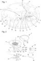
- the invention relates to a device for autonomously adjusting the active length of a hairspring, for a balance-spring type oscillator, comprising a cock mounted on a plate of a watch movement and in which a balance shaft pivots, the hairspring comprising an internal end secured to the balance shaft and an external end secured to a stud fixed to a stud holder, the stud holder being pivotally mounted on the cock concentrically to the balance shaft, and means for modifying the active length of the hairspring.
- An advantage of the adjustment device according to the invention lies in the fact that it comprises a weight mounted to rotate freely and cooperating indirectly with a movable arm arranged to act on the external coil of the balance spring.
- a rotation of the weight, freely subjected to gravity thus causes a movement of the arm, between a rest position and a correction position of the device, and simultaneously acts on the balance spring to modify the active length of the balance spring, making it possible to adjust the latter in order to compensate for the disturbances of the isochronism of the balance due to gravity.
- the adjustment device according to the invention makes it possible to precisely compensate for the rate of the oscillator according to its position in space, by counterbalancing the disturbances of the isochronism of the balance due to gravity, and this autonomously.
- the invention also relates to a watch movement comprising the adjustment device described above, and which comprises the characteristics mentioned in dependent claim 17.
- the invention also relates to a timepiece comprising the watch movement described above, and which comprises the characteristics mentioned in dependent claim 18.
- the means for modifying the active length of the hairspring 5 are capable of modifying the active length of the hairspring 5 by acting on the length of the external coil of the hairspring 5.
- the means for modifying the active length of the balance spring 5 comprise at least one arm 60 capable of moving between a rest position and a correction position of the device, the at least one arm having a first free end 600 and a second end 601 cooperating with a first pair of pins 19 forming a guide fork for the arm 60, the first pair of pins 19 being mounted on the stud holder 10 and angularly offset relative to the stud 8 via a first support 8'.
- the position of the first support 8' can be modified radially relative to the stud holder 10.
- the second end 601 of the arm 60 can slide between the two pins 19 and comes into contact with the external coil of the balance spring 5 in the correction position to modify the active length of the balance spring.
- the means for modifying the active length of the hairspring also comprise a weight 40 movable in rotation about an axis 41 on which is mounted at least one first cam 31 against which the free end 600 of the at least one arm rests.
- the weight 40 is arranged to be able to rotate about the axis 41 depending on the gravity to which it is subjected, the rotation of the weight 40 causing a rotation of the at least one cam 31 and a movement of at least one arm 60, 61 to act on the external coil of the hairspring and simultaneously modify the active length of the hairspring.
- the adjustment device 6 further comprises damping means comprising a toothed wheel 34 coaxial with the weight 40 and secured to the weight, and a damping device 20 arranged to cooperate with the weight 40 via the toothed wheel 34 and limit the modification of the active length of the balance spring 5 in the event of sudden acceleration or deceleration.
- the adjustment device comprises elastic constraint means configured to exert an elastic return action in position on the at least one arm 60.
- the elastic constraint means are in the form of a rod 62 secured to the arm 60 and a spring blade 63 secured to the stud holder 10, the spring blade 61 exerting a return force on the rod 62 to exert an elastic return action in position on the arm 60.
- the adjustment device comprises a second arm 61 capable of moving between a rest position and a correction position of the device, the second arm 61 having a first free end 610 and a second end cooperating with a second pair of pins 19' forming a guide fork for the second arm 61, the second pair of pins 19' being mounted on the stud holder 10 and angularly offset relative to the stud and to the first pair of pins 19 via a second support 8".
- the position of the second support 8" can be modified radially relative to the stud holder 10.
- the second end 611 of the second arm 61 can slide between the two pins 19' and comes into contact with the external coil of the hairspring in the correction position to modify the active length of the hairspring.
- the engagement means also comprise a second cam 32 arranged to cooperate with the second arm whose free end 610 rests against the second cam 32.
- Elastic constraint means are also associated with the second arm 61, and comprise a rod 64 secured to the second arm 61 and a spring blade 65 secured to the stud holder 10, the spring blade 65 exerting a return force on the rod 64 and exerting an elastic return action in position on the second arm 61.
- the adjustment device 6 also comprises means for adjusting the arms 60, 61, the free end 600, 610 of the first and second arms 60, 61 comprising elastically deformable adjustment means for lengthening or shortening the length of the arms.
- the adjustment means are in the form of a spring blade, a first end of which is secured to the arm and another end is free, the free end being arranged to be placed under stress and adjust the length of the arms 60, 61, the spring blade forming a space between it and the free end of each arm. Such an adjustment is necessary depending on the position of the hairspring and the correction to be made to the latter.
- the means for modifying the active length of the hairspring 5 comprise two pins 19 fixed to the second stud 8', the second end 601 of the arm 60 being arranged so that it slides between the two pins 19 and comes into contact with the external coil of the hairspring 5 in the correction position and thus modifies the active length of the hairspring.
- the means for modifying the active length of the spiral 5 further comprise two other pins 19' fixed to the third stud 8", the second end 611 of the second arm 61 being arranged so that it passes between the two pins 19' and comes into contact with the external coil of the balance spring in the correction position.
- each arm 60, 61 comprises means for adjusting the elastic stress, the adjustment means being in the form of a screw, the screw passing through the free end of the spring blade and bearing against the arm.
- the adjustment means being in the form of a screw, the screw passing through the free end of the spring blade and bearing against the arm.
- the weight 40 is mounted freely in rotation on the axis 41 on which the cams 31, 32 are mounted so that a rotation of the weight 40 causes a movement of the arms 60, 61 and acts simultaneously on the means for modifying the active length of the balance spring 5.
- the movement of the arms under the effect of the rotation of the weight 40, itself subject to gravity, is carried out between a rest position of the device, and a correction position of the device, each of the arms allowing a distinct correction according to the position of the watch.
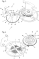
- the weight 40 is for example made up of a half-solid disk. In an alternative embodiment not shown in the figures, the weight 40 is made up of a solid two-material disk, the two materials of the disk having distinct densities.
- the weight 40 freely subjected to gravity, can rotate around its axis of rotation and thus cause a movement of the arms 60, 61. In doing so, this rotation of the weight 40 acts simultaneously on the means for modifying the active length of the balance spring 5, making it possible to adjust in continues the active length of the hairspring in order to compensate for disturbances in the isochronism of the balance wheel due to gravity.
- the adjustment device 6 comprises damping means comprising a toothed wheel 34 coaxial with the flyweight and secured to the latter.
- the damping means comprise a damping device arranged to cooperate with the flyweight via the toothed wheel to limit, or even prevent, the modification of the active length of the balance spring 5 during a sudden acceleration or deceleration.
- the damping device 20 is in the form of an air shock absorber, the shock absorber comprising a body 22 with a cavity in which a mass 21 of a shape similar to that of the cavity rotates about an axis 24.
- the axis 24 also comprises a pinion 23 arranged to cooperate with the teeth of the toothed wheel 34.
- the weight 40 moves, it drives the toothed wheel 34 which meshes with the pinion 23, and rotates the mass 21 of the damping device 20. It is therefore understood that during a sharp movement of the weight 40, the mass 21 will slow the rotation of the weight 40 by means of the damping device 20.
- other types of shock absorber can be put in place, such as a mass moving in a cylinder, or even a magnetic shock absorber.
- the shaft 30 carrying the weights 40, the toothed wheel 34 and the cams 31, 32 also comprises a third heart-shaped cam 33 secured to the shaft 30, and superimposed on the cams 31, 32.
- the third heart-shaped cam 33 is arranged to cooperate with a spring 24, 25 whose end 26 cooperates with the profile of the third heart-shaped cam 33, the assembly thus forming a device for resetting the position of the first and second arms 60, 61 to return them to their rest position naturally.
- the device 6 comprises two cams 31, 32 for driving the arms 60, 61.
- the cams 31, 32 are integral with the shaft 30, angularly offset from each other, and are each respectively in contact with the free end 600, 610 of the arms 60, 61.
- each cam 31, 32 is a radial cam with an external profile.
- radial cams with a substantially rectangular external profile are shown in the Figures 1 to 4 , in practice the shape envisaged for the external profile of each cam will depend on the type of spiral 5 used and the correction to be made to it.
- a radial cam with a triangular, oblong or even ovoid external profile can also be used in the context of the present invention.
- a flat portion of each cam is in contact with an arm 60, 61, while in the correction position of the device 6, a corner or an angle of the cam 31, 32 is in contact with the arm 60, 61. More preferably, as visible in the figures 1 , 3 and 4 , each cam 31, 32 is in contact with its respective arm whatever the position of the weight 40.
- the weight 40 freely subjected to gravity, can rotate about its axis of rotation and thus cause a movement of the arms 60, 61. In doing so, this rotation of the weight 40 acts simultaneously on the means for modifying the active length of the balance spring 5, making it possible to continuously adjust the active length of the balance spring in order to compensate for the disturbances of the isochronism of the balance due to gravity.
- the rotation of the weight 40 causes a rotation of the shaft 30 and has the effect of moving the cams 31, 32 which are integral with the shaft, the cams then acting on the free end 600, 610 of the arms 60, 61 and moving at least one of the arms 60, 61 so that the second end of one of the arms comes into contact with the hairspring 5 so as to modify the active length of the hairspring 5.
- the device will return by itself to the rest position thanks to the action of the spring 24, 25 on the third heart-shaped cam 33 which is also integral with the shaft 31.
- the invention also relates to a watch movement 2 comprising an oscillator 4, 5 of the balance-spring type and a device 6 for autonomous adjustment of the active length of the balance spring 5 as described previously.
- the invention also relates to a timepiece 1 comprising a watch movement 2 provided with a device 6 for autonomous adjustment of the active length of the balance spring 5 as described previously.
Landscapes
- Physics & Mathematics (AREA)
- General Physics & Mathematics (AREA)
- Life Sciences & Earth Sciences (AREA)
- Atmospheric Sciences (AREA)
- Transmission Devices (AREA)
Applications Claiming Priority (1)
| Application Number | Priority Date | Filing Date | Title |
|---|---|---|---|
| EP23160130.3A EP4428623A1 (de) | 2023-03-06 | 2023-03-06 | Vorrichtung zur autonomen einstellung der aktiven länge einer spiralfeder |
Publications (2)
| Publication Number | Publication Date |
|---|---|
| EP4428626A1 true EP4428626A1 (de) | 2024-09-11 |
| EP4428626B1 EP4428626B1 (de) | 2025-11-19 |
Family
ID=85505616
Family Applications (2)
| Application Number | Title | Priority Date | Filing Date |
|---|---|---|---|
| EP23160130.3A Withdrawn EP4428623A1 (de) | 2023-03-06 | 2023-03-06 | Vorrichtung zur autonomen einstellung der aktiven länge einer spiralfeder |
| EP24153712.5A Active EP4428626B1 (de) | 2023-03-06 | 2024-01-24 | Vorrichtung zur autonomen einstellung der aktiven länge einer spiralfeder |
Family Applications Before (1)
| Application Number | Title | Priority Date | Filing Date |
|---|---|---|---|
| EP23160130.3A Withdrawn EP4428623A1 (de) | 2023-03-06 | 2023-03-06 | Vorrichtung zur autonomen einstellung der aktiven länge einer spiralfeder |
Country Status (4)
| Country | Link |
|---|---|
| US (1) | US20240302794A1 (de) |
| EP (2) | EP4428623A1 (de) |
| JP (1) | JP7642884B2 (de) |
| CN (1) | CN118605102A (de) |
Citations (3)
| Publication number | Priority date | Publication date | Assignee | Title |
|---|---|---|---|---|
| CH705605B1 (fr) | 2011-10-14 | 2016-10-14 | Frederique Constant S A | Dispositif de réglage de la longueur active d'un spiral. |
| EP3081996A1 (de) * | 2015-04-16 | 2016-10-19 | Montres Breguet S.A. | Spirale aus mikrobearbeitbarem material mit isochronismus-korrektur |
| EP3502788A1 (de) * | 2017-12-20 | 2019-06-26 | The Swatch Group Research and Development Ltd | Vorrichtung zur selbstregulierung der aktiven länge einer spirale |
-
2023
- 2023-03-06 EP EP23160130.3A patent/EP4428623A1/de not_active Withdrawn
-
2024
- 2024-01-24 EP EP24153712.5A patent/EP4428626B1/de active Active
- 2024-01-30 US US18/426,573 patent/US20240302794A1/en active Pending
- 2024-02-08 JP JP2024017667A patent/JP7642884B2/ja active Active
- 2024-03-06 CN CN202410254826.4A patent/CN118605102A/zh active Pending
Patent Citations (3)
| Publication number | Priority date | Publication date | Assignee | Title |
|---|---|---|---|---|
| CH705605B1 (fr) | 2011-10-14 | 2016-10-14 | Frederique Constant S A | Dispositif de réglage de la longueur active d'un spiral. |
| EP3081996A1 (de) * | 2015-04-16 | 2016-10-19 | Montres Breguet S.A. | Spirale aus mikrobearbeitbarem material mit isochronismus-korrektur |
| EP3502788A1 (de) * | 2017-12-20 | 2019-06-26 | The Swatch Group Research and Development Ltd | Vorrichtung zur selbstregulierung der aktiven länge einer spirale |
Also Published As
| Publication number | Publication date |
|---|---|
| JP2024126006A (ja) | 2024-09-19 |
| EP4428626B1 (de) | 2025-11-19 |
| US20240302794A1 (en) | 2024-09-12 |
| JP7642884B2 (ja) | 2025-03-10 |
| EP4428623A1 (de) | 2024-09-11 |
| CN118605102A (zh) | 2024-09-06 |
Similar Documents
| Publication | Publication Date | Title |
|---|---|---|
| EP3502788B1 (de) | Vorrichtung zur selbstregulierung der aktiven länge einer spirale | |
| CH709052B1 (fr) | Balancier-spiral, mouvement et pièce d'horlogerie. | |
| CH705605A2 (fr) | Dispositif de réglage de la longueur active d'un spiral. | |
| EP4286962A1 (de) | Regulierorgan für uhr, das eine rückervorrichtung umfasst, die mit verriegelungsmitteln ausgestattet ist | |
| EP4428627B1 (de) | Vorrichtung zur autonomen einstellung der aktiven länge einer spiralfeder | |
| EP4428626B1 (de) | Vorrichtung zur autonomen einstellung der aktiven länge einer spiralfeder | |
| EP4286961A1 (de) | Uhrregulierungsorgan mit einer präzisionsrückervorrichtung | |
| EP4428624B1 (de) | Vorrichtung zur autonomen einstellung der aktiven länge einer spiralfeder | |
| CH720583A2 (fr) | Dispositif de réglage autonome de la longueur active d'un spiral | |
| EP4428628B1 (de) | Vorrichtung zur autonomen einstellung der aktiven länge einer spiralfeder | |
| CH720582A2 (fr) | Dispositif de réglage autonome de la longueur active d'un spiral | |
| CH720584A2 (fr) | Dispositif de réglage autonome de la longueur active d'un spiral | |
| CH720580A2 (fr) | Dispositif de réglage autonome de la longueur active d'un spiral | |
| EP3391154B1 (de) | Schwingsystem für eine uhr | |
| EP4432020A1 (de) | Uhrwerk | |
| CH719990B1 (fr) | Dispositif de pitonnage et d'ajustement de la longueur active d'un ressort spiral pour mouvement horloger ainsi que procédé de réglage de la longueur active | |
| CH716423B1 (fr) | Ensemble limiteur d'horlogerie pour une montre comportant au moins un tourbillon ou un carrousel. | |
| EP4521173A1 (de) | Uhrvorrichtung | |
| EP4498176A1 (de) | Regulierungsorgan für uhren, das mit einem linearem betätigungssystem augerustet ist | |
| EP4498174A1 (de) | Regulierorgan für uhren, das ein betätigungssystem mit einer steuerwippe umfasst | |
| EP4492157A1 (de) | Verfahren zur einstellung des isochronismus eines spiral-unruh-reglers | |
| EP3770695B1 (de) | Anschlagkäfig für uhr mit käfiganschlagblatt | |
| EP4715484A1 (de) | Uhrvorrichtung mit unruhspiralfeder und mittel zur einstellung der liegend-hängend | |
| CH720948A1 (fr) | Procédé de réglage de l'isochronisme d'un organe régulateur de type balancier-spiral | |
| EP4498175A1 (de) | Uhreinstellorgan mit hakenbetätigungssystem |
Legal Events
| Date | Code | Title | Description |
|---|---|---|---|
| PUAI | Public reference made under article 153(3) epc to a published international application that has entered the european phase |
Free format text: ORIGINAL CODE: 0009012 |
|
| STAA | Information on the status of an ep patent application or granted ep patent |
Free format text: STATUS: THE APPLICATION HAS BEEN PUBLISHED |
|
| AK | Designated contracting states |
Kind code of ref document: A1 Designated state(s): AL AT BE BG CH CY CZ DE DK EE ES FI FR GB GR HR HU IE IS IT LI LT LU LV MC ME MK MT NL NO PL PT RO RS SE SI SK SM TR |
|
| STAA | Information on the status of an ep patent application or granted ep patent |
Free format text: STATUS: REQUEST FOR EXAMINATION WAS MADE |
|
| P01 | Opt-out of the competence of the unified patent court (upc) registered |
Free format text: CASE NUMBER: APP_6838/2025 Effective date: 20250210 |
|
| 17P | Request for examination filed |
Effective date: 20250311 |
|
| GRAP | Despatch of communication of intention to grant a patent |
Free format text: ORIGINAL CODE: EPIDOSNIGR1 |
|
| STAA | Information on the status of an ep patent application or granted ep patent |
Free format text: STATUS: GRANT OF PATENT IS INTENDED |
|
| RIC1 | Information provided on ipc code assigned before grant |
Ipc: G04B 18/02 20060101AFI20250707BHEP Ipc: G04B 18/06 20060101ALI20250707BHEP |
|
| INTG | Intention to grant announced |
Effective date: 20250723 |
|
| GRAS | Grant fee paid |
Free format text: ORIGINAL CODE: EPIDOSNIGR3 |
|
| GRAA | (expected) grant |
Free format text: ORIGINAL CODE: 0009210 |
|
| STAA | Information on the status of an ep patent application or granted ep patent |
Free format text: STATUS: THE PATENT HAS BEEN GRANTED |
|
| AK | Designated contracting states |
Kind code of ref document: B1 Designated state(s): AL AT BE BG CH CY CZ DE DK EE ES FI FR GB GR HR HU IE IS IT LI LT LU LV MC ME MK MT NL NO PL PT RO RS SE SI SK SM TR |
|
| REG | Reference to a national code |
Ref country code: CH Ref legal event code: F10 Free format text: ST27 STATUS EVENT CODE: U-0-0-F10-F00 (AS PROVIDED BY THE NATIONAL OFFICE) Effective date: 20251119 Ref country code: GB Ref legal event code: FG4D Free format text: NOT ENGLISH |
|
| REG | Reference to a national code |
Ref country code: CH Ref legal event code: R17 Free format text: ST27 STATUS EVENT CODE: U-0-0-R10-R17 (AS PROVIDED BY THE NATIONAL OFFICE) Effective date: 20251204 |
|
| REG | Reference to a national code |
Ref country code: DE Ref legal event code: R096 Ref document number: 602024001266 Country of ref document: DE |
|
| REG | Reference to a national code |
Ref country code: IE Ref legal event code: FG4D Free format text: LANGUAGE OF EP DOCUMENT: FRENCH |
|
| PGFP | Annual fee paid to national office [announced via postgrant information from national office to epo] |
Ref country code: FR Payment date: 20251217 Year of fee payment: 3 |