EP4428470A1 - Wärmepumpensystem - Google Patents
Wärmepumpensystem Download PDFInfo
- Publication number
- EP4428470A1 EP4428470A1 EP24157536.4A EP24157536A EP4428470A1 EP 4428470 A1 EP4428470 A1 EP 4428470A1 EP 24157536 A EP24157536 A EP 24157536A EP 4428470 A1 EP4428470 A1 EP 4428470A1
- Authority
- EP
- European Patent Office
- Prior art keywords
- heat pump
- opening
- connections
- pump system
- electrical
- Prior art date
- Legal status (The legal status is an assumption and is not a legal conclusion. Google has not performed a legal analysis and makes no representation as to the accuracy of the status listed.)
- Pending
Links
Images




Classifications
-
- F—MECHANICAL ENGINEERING; LIGHTING; HEATING; WEAPONS; BLASTING
- F24—HEATING; RANGES; VENTILATING
- F24H—FLUID HEATERS, e.g. WATER OR AIR HEATERS, HAVING HEAT-GENERATING MEANS, e.g. HEAT PUMPS, IN GENERAL
- F24H9/00—Details
- F24H9/02—Casings; Cover lids; Ornamental panels
-
- F—MECHANICAL ENGINEERING; LIGHTING; HEATING; WEAPONS; BLASTING
- F24—HEATING; RANGES; VENTILATING
- F24H—FLUID HEATERS, e.g. WATER OR AIR HEATERS, HAVING HEAT-GENERATING MEANS, e.g. HEAT PUMPS, IN GENERAL
- F24H4/00—Fluid heaters characterised by the use of heat pumps
- F24H4/02—Water heaters
-
- F—MECHANICAL ENGINEERING; LIGHTING; HEATING; WEAPONS; BLASTING
- F24—HEATING; RANGES; VENTILATING
- F24H—FLUID HEATERS, e.g. WATER OR AIR HEATERS, HAVING HEAT-GENERATING MEANS, e.g. HEAT PUMPS, IN GENERAL
- F24H9/00—Details
- F24H9/12—Arrangements for connecting heaters to circulation pipes
Definitions
- the present invention relates to the field of heat pumps and in particular to a heat pump system comprising a heat pump and a housing, the heat pump system further comprising hydraulic connections and electrical connections.
- a heat pump i.e. a heat pump system
- a location intended for the heat pump e.g. a base
- hydraulic connections and electrical connections intended for connecting the hydraulic lines and electrical lines to the heat pump are arranged on a rear side of the heat pump or the heat pump system. This allows the length of the hydraulic lines and electrical lines to be kept short and the connections can be easily hidden by the heat pump.
- a connection housing outside the heat pump housing can be useful in order to further protect the connections from view and weather influences after the hydraulic lines and electrical lines have been connected to the heat pump.
- the hydraulic lines and electrical lines can also be routed from a lower side of the heat pump to connections provided for this purpose.
- An aim underlying the present invention is to simplify installation of the heat pump with regard to the hydraulic connections and the electrical connections for heat pumps which are arranged with a back against a wall, while concealing the hydraulic lines and electrical lines by the heat pump or the housing of the heat pump system.
- a heat pump system is proposed as defined in claim 1, namely a heat pump system with a heat pump and a housing, wherein the housing comprises a rear wall, at least one side wall and a base plate, wherein the heat pump system comprises hydraulic connections and electrical connections, wherein the rear wall and/or the base plate has a first opening for laying, i.e.
- connection direction for connection to electrical lines and an assembly direction arranged at a second angle to the connection direction for mounting the electrical lines to the electrical connections, wherein the connection direction points in the direction of the rear wall of the heat pump and wherein the assembly direction points in the direction of the side wall of the heat pump.
- a method is proposed as defined in claim 19, namely a method for assembling a heat pump system with a heat pump and a housing, wherein the housing comprises a rear wall, at least one side wall and a base plate, wherein the heat pump system comprises hydraulic connections and electrical connections, the method comprising the steps of: (i) deciding whether hydraulic lines are to be led through a first opening on the rear wall or a first opening on the base plate of the heat pump, (ii) laying the hydraulic lines through the first opening, (iii) connecting the hydraulic lines to the hydraulic connections, (iv) laying electrical lines through the first opening in the direction of the electrical connections, (v) mounting the electrical lines to the electrical connections through a second opening on the side wall of the heat pump, and (vi) routing the electrical lines at least partially from the first opening to the electrical connections.
- Such an arrangement of the hydraulic connections and the electrical connections in the heat pump enables, on the one hand, the hydraulic lines and electrical lines to be protected or covered by the heat pump system or the housing of the heat pump and, on the other hand, the hydraulic lines and electrical lines to be easily installed on the heat pump regardless of whether the heat pump is positioned with a rear wall close to a wall, e.g. a house wall.
- the heat pump is preferably an air/water heat pump, whereby the heat pump is preferably intended and suitable for outdoor installation.
- the housing of the heat pump preferably surrounds the entire heat pump.
- the housing comprises at least one rear wall, two side walls, a base plate, a front side and a cover, the front side preferably comprising an exhaust grille.
- the rear wall is the wall of the heat pump opposite the exhaust grille.
- the hydraulic connections are arranged in a corner of the heat pump between a rear wall and a side wall.
- the electrical connections are preferably arranged next to the hydraulic connections on a side wall.
- the housing comprises at least one side surface that corresponds to a jacket surface of the cylinder describing the heat pump, a base plate and a cover.
- the side surface comprises a rear wall that corresponds to a first partial area of the side surface, which is preferably arranged opposite a second partial area of the side surface that comprises the exhaust grille.
- the hydraulic connections are arranged in a partial area of the side surface, ie the rear wall, with the electrical connections being arranged next to the hydraulic connections on a side wall.
- “next to” means that the electrical connections are either arranged directly next to the hydraulic connections or that other parts of the heat pump can be arranged between the electrical connections and the hydraulic connections.
- the hydraulic connections are advantageously designed to provide a water inlet connection for connection to a water inlet and a water return connection for connection to a water return, wherein the water inlet connection and the water return connection are each aligned towards the rear of the heat pump or towards the base plate of the heat pump.
- the water inlet connection and the water return connection are aligned in the same direction, wherein alternatively one of the water inlet connection and the water return connection can be aligned towards the rear of the heat pump and a second of the water inlet connection and the water return connection can be aligned towards the base plate of the heat pump.
- the hydraulic connections correspond in particular to water connections.
- the hydraulic connections can comprise any variants known for hydraulic connections, for example screw threads or quick couplings.
- the electrical connections are preferably designed to provide one or more energy supply connections for supplying the heat pump with electrical energy and/or one or more control connections for connection to a control unit of the heat pump.
- the electrical connections can comprise any variants known for electrical connections, for example screw terminals, such as screw terminals, or clip-in terminals.
- the rear wall and/or the base plate of the heat pump housing has a first opening for laying hydraulic lines to the hydraulic connections.
- the rear wall can advantageously comprise the first opening, wherein the rear wall can alternatively also comprise a further opening that does not correspond to the first opening.
- the opening in the rear wall can be closed by a rear flap.
- the base plate can advantageously comprise the first opening, wherein the base plate can alternatively also comprise a further opening that does not correspond to the first opening.
- the opening in the base plate can be closed.
- the base plate preferably has a predetermined breaking point for cutting out part of the base plate, wherein in a case in which the hydraulic lines are laid through a first opening in the base plate, the part of the base plate is cut out at the predetermined breaking point. Furthermore, in a case where the hydraulic lines are routed through a first opening in the rear wall, the part of the base plate is not cut out and thus the opening in the base plate is closed.
- a size of the first opening is selected such that at least the hydraulic lines can be laid through the first opening, ie fit spatially through the first opening, wherein the size of the first opening can be adapted such that a corresponding additional area is provided for connecting the hydraulic lines to the hydraulic connections.
- the first opening is also provided for laying electrical cables to the electrical connections, wherein a size of the first opening is then selected such that the electrical cables can also be laid through the first opening, i.e. they fit spatially through the first opening.
- the side wall of the heat pump housing has a second opening for access to the electrical connections.
- This means that the second opening is intended for mounting, i.e. for connecting, the electrical cables to the electrical connections.
- the second opening in the side wall has a size that is defined by a size of the electrical connections, i.e. for example by a size of a plate on which the electrical connections are attached.
- the first opening and the second opening are arranged at a first angle ⁇ to one another, wherein preferably an angle between 10° and 170°, particularly preferably between 85° and 95°, is provided.
- the first angle between the first opening and the second opening is preferably 90°, wherein the first opening and the second opening are then arranged perpendicular to one another.
- the first angle is preferably 90° in a case in which the first opening is provided in the base plate and preferably between 90° and 180° in a case in which the first opening is provided in the rear wall.
- the electrical connections have a connection direction and a mounting direction, the connection direction being intended for connection to electrical lines and the mounting direction being intended for mounting the electrical lines to the electrical connections.
- the connection direction is arranged at a second angle ⁇ to the mounting direction, the second angle preferably corresponding to 85° to 95°, particularly preferably 90°.
- the connection direction of the electrical connections points in the direction of the rear wall of the heat pump and the mounting direction of the electrical connections points in the direction of the side wall of the heat pump.
- the heat pump system has an intermediate wall that is arranged inside the housing of the heat pump.
- the intermediate wall is arranged perpendicular to a side wall of the heat pump, with the intermediate wall preferably contacting the side wall of the heat pump.
- the intermediate wall can preferably have openings through which, for example, electrical cables are laid.
- a first space is defined or delimited by the rear wall of the housing of the heat pump, the side wall of the housing of the heat pump and the intermediate wall, with the hydraulic connections being arranged in the first space.
- a second space is defined or delimited by the intermediate wall and the side wall, with the electrical connections being arranged in the second space.
- the intermediate wall is therefore arranged between the first space and the second space.
- the first space and the second space do not overlap.
- the intermediate wall is not necessarily provided if the hydraulic connections and the electrical connections are arranged in a first space and in a second space, as stated above. This means that an arrangement of a first room and a second room, in particular the hydraulic connections in the first room and the electrical connections in the second room, is also possible without a partition wall.
- the second opening provides an opening into the first space and into the second space.
- the first space and the second space each have openings to a side wall that correspond to a common opening.
- the second space is then preferably at least partially open to a side wall, i.e. to the second opening of the side wall, of the heat pump housing.
- the heat pump system has a guide element that is designed to at least partially guide electrical cables from the rear wall to the electrical connections.
- the guide element is preferably arranged perpendicular to a side wall and/or parallel to a rear wall of the heat pump.
- the guide element is preferably designed to at least partially guide electrical cables from the first room into the second room.
- a "guide” in the context of the guide element means that the electrical cables are guided along a predetermined path, whereby a "partial guide” means that the electrical cables are partially guided along a predetermined path.
- a complete guide between the rear wall and electrical connections or from the first room into the second room is not necessary, but can be provided.
- the guide element can preferably be arranged in the first space, whereby the guide element can alternatively be arranged between the first space and the second space, e.g. as part of the intermediate wall. Further alternatively, the guide element can also be arranged in the second space.
- the guide element has openings, wherein the openings are designed to guide the electrical cables laid through the openings on a predetermined path.
- the openings of the guide element can be at least partially open to an edge of the guide element in the direction of the side wall of the heat pump.
- at least some of the openings or all of the openings of the guide element can be open to an edge of the guide element in the direction of a side flap (see below) for the side wall of the heat pump.
- the guide element can be designed as a perforated plate, in which case an open opening in the direction of the side wall of the heat pump can be realized by cutting through the holes in the perforated plate.
- the hydraulic connections are arranged entirely within the housing of the heat pump. "Entirely within the housing” means that the hydraulic connections are arranged in a volume that is defined by an outer side of the housing of the heat pump.
- the hydraulic connections are preferably oriented towards the rear wall of the heat pump and/or towards the base plate of the heat pump.
- the hydraulic connections are preferably oriented towards the rear wall.
- the hydraulic connections are preferably oriented towards the base plate.
- the first opening is provided through an opening in the rear wall and a further opening in the base plate, a part of the hydraulic lines and the electrical lines run through the opening in the rear wall of the heat pump and a further part of the hydraulic lines and the electrical lines run through the further opening in the base plate of the heat pump, i.e.
- the opening in the rear wall of the heat pump and the further opening in the base plate of the heat pump form the first opening.
- a part of the hydraulic connections are preferably oriented towards the rear wall and a further part of the hydraulic connections are preferably oriented towards the base plate.
- the side flap can be reversibly mounted separately from the side wall.
- the side wall and the side flap are designed in two pieces, whereby the side flap can be attached to the side wall, for example by snapping it into place and/or screwing it to the side wall.
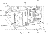
- Fig.1 shows a schematic representation to illustrate a first embodiment of the heat pump system.
- the heat pump system 100 shown comprises a heat pump and a housing, wherein in Fig.1 only part of the heat pump and part of the housing can be seen.
- a base plate 110 of the housing is shown as well as hydraulic connections 120 and electrical connections 130.
- the hydraulic connections 120 are provided in a rear left corner of the heat pump, wherein the electrical connections 130 are arranged on a left side of the heat pump next to the hydraulic connections 120.
- the arrangement of the hydraulic connections 120 and the electrical connections 130 can also be understood as a connection arrangement.
- the connection arrangement is arranged directly on the base plate 110.
- a rear side of the heat pump is in Fig.1 arranged diagonally to the left, a left side of the heat pump shows in Fig.1 diagonally to the bottom right.
- a rear wall and a left side wall of the heat pump housing are in Fig.1 not shown.
- the hydraulic connections 120 are aligned in the direction of the base plate 110 of the heat pump.
- the hydraulic connections 120 are designed to provide a water inlet connection for connection to a water inlet and a water return for connection to a water return.
- the water inlet connection and the water return connection are aligned in the direction of the base plate 110 of the heat pump.
- An alignment of the hydraulic connections in the direction of the base plate 110 is not achieved in the present embodiment. realized by an angle connection that extends and redirects the hydraulic connections from the hydraulic connections aligned to the rear of the heat pump towards the base plate of the heat pump.
- the hydraulic connections 120 are surrounded by an inner wall 141 and an intermediate wall 142, wherein the inner wall 141 and the intermediate wall 142 have openings.
- an inner wall 141 or an intermediate wall 142 can be designed to be so short that there is an opening between the inner wall 141 and the intermediate wall.
- the inner wall 141 is arranged parallel to a side wall of the heat pump housing.
- the intermediate wall 142 is arranged between the hydraulic connections 120 and the electrical connections 130.
- the intermediate wall 142 can be provided to hold the hydraulic connections 120.
- a first space 150 is delimited by at least the rear wall of the heat pump housing, the side wall of the heat pump housing and the intermediate wall 142, wherein the hydraulic connections 120 are arranged in the first space 150.
- a second space is delimited by at least the side wall of the housing of the heat pump and the intermediate wall 142, wherein the electrical connections 130 are arranged in the second space 160.
- the electrical connections 130 are designed to provide one or more energy supply connections for supplying the heat pump with electrical energy and/or one or more control connections for connection to a control unit of the heat pump.
- the electrical connections 130 are arranged in an inner housing 140, wherein the inner housing 140 in the embodiment shown is arranged on four sides around the electrical connections 130.
- the rear wall of the heat pump and/or the base plate 110 of the heat pump has a first opening for laying hydraulic lines to the hydraulic connections 120.
- a punched-out sheet is provided in the base plate 110, which is preferably not punched out in a case in which the rear wall has the first opening for laying hydraulic lines, and is preferably punched out in a case in which the rear wall does not have the first opening for laying hydraulic lines.
- the base plate 110 comprises a predetermined breaking point for cutting out a part of the base plate 110.
- the side wall of the housing of the heat pump comprises a second opening for accessing the electrical connections 130, i.e. for mounting electrical cables on the electrical connections 130.
- the first opening and the second opening are arranged at a first angle to each other.
- the first opening and the second opening are arranged perpendicular to each other, i.e. a first angle corresponds to a value of 90°.
- the electrical connections 130 have a connection direction for connection to electrical lines, wherein the connection direction points in the direction of the rear wall of the heat pump. Furthermore, the electrical connections 130 have a mounting direction arranged at a second angle to the connection direction for mounting the electrical lines to the electrical connections 130, wherein the mounting direction points in the direction of the side wall of the heat pump. In the embodiment shown, the connection direction of the electrical connections 130 is arranged perpendicular to the mounting direction, i.e. a second angle corresponds to a value of 90°.
- the second opening of the side wall can extend over the first space 150 or over the first space 150 and the second space 160, i.e. the second opening preferably provides an opening into the first space and into the second space.
- a side flap is provided for the second opening, which is provided on the side wall of the heat pump and covers the first space 150 and/or the second space 160 in the direction of the side wall of the heat pump.
- a rear flap and/or a bottom flap can also be provided to cover the first opening.
- the rear flap and/or the bottom flap can have further openings that are provided for the hydraulic lines or electrical lines.
- a rear flap can have a U-shape.
- the side flap and/or the rear flap can be reversibly mounted separately from the side wall or the rear wall, i.e. can be detached from the side wall or the rear wall using tools, for example.
- the heat pump system 100 shown has a guide element 170 which is designed to at least partially guide electrical cables from the first space 150 into the second space 160.
- the guide element 170 is designed to guide electrical cables from a rear side of the heat pump to the electrical connections 130.
- the guide element 170 is arranged in the first space 150, whereby the guide element 170 can alternatively be arranged, for example, between the first space 150 and the second space 160.
- the guide element 170 can be designed as part of the intermediate wall 142.
- the guide element 170 is perpendicular to the inner wall 141 in the direction of the side wall of the heat pump.
- the guide element 170 has openings through which electrical cables are at least partially guided from the first space 150 into the second space 160 or from a rear side of the heat pump to the electrical connections 130. At least some of the openings, in the present case all of the openings, are open to an edge of the guide element 170 in the direction of a side wall of the heat pump, i.e. the openings are open to an edge of the guide element 170 when the side wall, in particular a side flap of the side wall, is not mounted and are closed when the side wall, in particular a side flap of the side wall, is mounted.
- the guide element 170 can correspond to a perforated plate, wherein the perforated plate then preferably has openings to an edge of the guide element 170 in the direction of the side wall of the heat pump.
- the hydraulic connections 120 are arranged completely within the housing of the heat pump, i.e. the hydraulic connections do not protrude from the first space 150 defined by the housing, i.e. the hydraulic connections 120 do not protrude from a volume defined by the housing of the heat pump.
- the hydraulic connections are located in a footprint of the housing of the heat pump.
- Fig.2 shows a schematic representation to illustrate a second embodiment of the heat pump system with a side wall.
- the heat pump system 100 comprises a side wall 210 and a rear wall 240.
- the heat pump system 100 further comprises hydraulic connections 220 and electrical connections 130.
- the hydraulic connections 220 are partially covered by the rear wall 240 and are therefore only partially visible.
- the electrical connections 130 can be seen through an opening which corresponds to the second opening 230.
- the side wall 210 of the heat pump has an opening which corresponds to the second opening 230.
- a size of the second opening 230 of the side wall 210 essentially corresponds to a size which is defined by the electrical connections 130.
- an opening can also be provided which corresponds to a common opening of the first space 150 and the second space 160 in the direction of the side wall 210 of the heat pump.
- a size of the second opening 230 is essentially defined by a width of the first space 150 and the second space 160.
- the second opening 230 then provides an opening into the first space 150 and an opening into the second space 160, wherein in the present case an inner wall (not shown) is at least partially open towards the side wall of the housing of the heat pump.
- the hydraulic connections 120 point in the direction of a rear wall 240 of the heat pump.
- the first opening 250 is arranged on the rear wall 240, wherein a rear flap can be provided on the rear wall 240 to partially cover the first opening 250, which can be shaped as a "U", for example.
- Fig.3 shows a further schematic representation to illustrate the second embodiment of the heat pump system.
- Hydraulic connections 320 can be seen, which comprise a T-piece and are thus aligned both towards the rear wall of the heat pump and towards the base plate of the heat pump.
- Fig.3 further shows a side flap 310 for covering the second opening 230 in the direction of the side wall of the heat pump.
- the side flap 310 is designed to cover the electrical connections 130 in the second space 160, although alternatively the side flap can also be designed wider in order to also cover the first space 150.
- the side flap 310 can be designed to cover a second opening 230, which provides an opening into the first space 150 and into the second space 160.
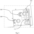
- Fig.4 shows a schematic diagram to illustrate the second embodiment of the heat pump system from a different perspective. This makes it possible to Fig.4 the guide element 170 can be seen.
- the guide element 170 has openings through which electrical lines are guided.
- the guide element 170 is at least partially open to an edge of the guide element 170 in the direction of the side wall 210 of the heat pump, ie at least some of the openings of the guide element 170 are open in the direction of the side wall 210 of the heat pump.
- Fig.4 it can be seen that the guide element 170 is closed off by the side wall of the heat pump at the edge of the guide element 170, ie that the openings open in the direction of the side wall 210 of the heat pump are closed by the side wall 210 of the heat pump.
- further guide elements 410 are shown for guiding electrical cables from a rear side of the heat pump to the electrical connections 130.
- Fig.5 shows a schematic representation to illustrate the second embodiment of the heat pump system with regard to the hydraulic connections.
- the hydraulic connections 220 are in the embodiment shown only aligned towards the rear of the heat pump.
- the other in Fig.5 The features shown essentially correspond to the features of Fig.4 .
- Fig.6 shows a schematic representation to illustrate another embodiment of the heat pump system with regard to the hydraulic connections.
- the hydraulic connections 120 which are similar to those in Fig.1 correspond, in the direction of a base plate of the heat pump.
- the other Fig.6 The features shown correspond essentially to those shown in the Fig.4 and 5 features shown.
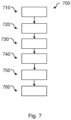
- Fig.7 shows a schematic flow diagram to illustrate a first embodiment of the method according to the invention.
- the method is provided for assembling a heat pump system with a heat pump and a housing.
- the housing comprises at least one rear wall, at least one side wall and a base plate, the heat pump system further comprising hydraulic connections and electrical connections.
- a decision is made as to whether hydraulic lines are to be laid through a first opening in the wall or a first opening in the base plate of the heat pump.
- a part of the base plate which is connected to the rest of the base plate for example by a predetermined breaking point, can be cut out.
- a next step 720 the hydraulic lines are laid through the first opening. In a case where it is decided that the hydraulic lines should be routed through a first opening in the rear wall, the hydraulic lines are routed through the first opening on the rear wall; in a case where it is decided that the hydraulic lines should be routed through a first opening in the base plate, the hydraulic lines are routed through the first opening on the base plate. In a next step 730, the hydraulic lines are connected to the hydraulic connections.
- a step 740 electrical cables are laid through the first opening in the direction of the electrical connections.
- the electrical cables are laid through the first opening in the rear wall
- the electrical cables are laid through the first opening in the base plate.
- the electrical cables are mounted to the electrical connections through a second opening on the side wall of the heat pump.
- the electrical cables are at least partially guided from the first opening to the electrical connections, preferably by a guide element.
- the invention relates to a heat pump system with a heat pump and a housing, wherein the housing comprises a rear wall, at least one side wall and a base plate, wherein the heat pump system comprises hydraulic connections and electrical connections.
- the rear wall and/or the base plate has a first opening for laying, i.e. passing through, hydraulic lines to the hydraulic connections, wherein the side wall has a second opening for accessing the electrical connections, wherein the first opening and the second opening are arranged at a first angle to each other.
- the electrical connections have a connection direction for connection to electrical lines and an assembly direction arranged at a second angle to the connection direction for mounting the electrical lines to the electrical connections, wherein the connection direction points in the direction of the rear wall of the heat pump and wherein the assembly direction points in the direction of the side wall of the heat pump.
Landscapes
- Engineering & Computer Science (AREA)
- Physics & Mathematics (AREA)
- Thermal Sciences (AREA)
- Chemical & Material Sciences (AREA)
- Combustion & Propulsion (AREA)
- Mechanical Engineering (AREA)
- General Engineering & Computer Science (AREA)
- Details Of Reciprocating Pumps (AREA)
Abstract
Description
- Die vorliegende Erfindung betrifft das Gebiet von Wärmepumpen und insbesondere ein Wärmepumpensystem mit einer Wärmepumpe und einem Gehäuse, wobei das Wärmepumpensystem weiter Hydraulikanschlüsse und Elektroanschlüsse umfasst.
- Nach Aufstellen einer Wärmepumpe, d. h. eines Wärmepumpensystems, an einem für die Wärmepumpe vorgesehenen Platz, z.B. einem Aufstellsockel, ist es erforderlich, die Wärmepumpe sowohl an für die Wärmepumpe vorgesehene Hydraulikleitungen als auch für die Wärmepumpe vorgesehene Elektroleitungen anzuschließen.
- Es ist bekannt, dass Hydraulikanschlüsse und Elektroanschlüsse, die für ein Anschließen der Hydraulikleitungen und der Elektroleitungen an die Wärmepumpe vorgesehen sind, an einer Rückseite der Wärmepumpe bzw. das Wärmepumpensystems angeordnet sind. Dadurch kann eine Länge der Hydraulikleitungen und der Elektroleitungen gering gehalten werden und die Anschlüsse leicht durch die Wärmepumpe verdeckt werden. In einem Fall, in dem die Hydraulikanschlüsse und die Elektroanschlüsse an einer Rückseite der Wärmepumpe vorgesehen sind, kann ein Anschlussgehäuse außerhalb des Gehäuses der Wärmepumpe sinnvoll sein, um die Anschlüsse nach Anschließen der Hydraulikleitungen und der Elektroleitungen an die Wärmepumpe weiter vor Sicht und Wettereinflüssen zu schützen. Alternativ können die Hydraulikleitungen und die Elektroleitungen auch von einer unteren Seite der Wärmepumpe an dafür vorgesehene Anschlüsse verlegt werden.
- In einem Fall, in dem die Wärmepumpe mit einer Rückseite der Wärmepumpe an einer Wand, z.B. einer Hauswand, angeordnet ist, sind Hydraulikanschlüsse und Elektroanschlüsse an der Rückseite allerdings von Nachteil, weil ein Zugriff auf die Hydraulikanschlüsse und Elektroanschlüsse für einen Installateur räumlich stark begrenzt ist. Auch wenn ein Installieren, d. h. Anschließen der Hydraulikleitungen und Elektroleitungen während eines Aufstellens der Wärmepumpe vorgenommen werden kann, so dass zunächst die Hydraulikleitungen und Elektroleitungen an die Wärmepumpe angeschlossen werden und dann die Wärmepumpe an die rechtmäßige Position nahe der Wand gestellt wird, um dem Installateur mehr Raum zum Anschließen zu bieten, ist dann weiterhin ein nachträgliches Erreichen der Anschlüsse, z.B. im Falle eines Fehlers oder eines Lecks, für den Installateur kaum möglich.
- Ein der vorliegenden Erfindung zugrundeliegendes Ziel ist es, ein Installieren der Wärmepumpe hinsichtlich der Hydraulikanschlüsse und der Elektroanschlüsse für Wärmepumpen, die mit einer Rückseite an einer Wand angeordnet sind, zu vereinfachen und dabei die Hydraulikleitungen und Elektroleitungen durch die Wärmepumpe bzw. das Gehäuse des Wärmepumpensystems zu verdecken.
- Es ist daher gewünscht, eine Lösung vorzustellen, die ein Installieren von Hydraulikleitungen und Elektroleitungen an einer Wärmepumpe vereinfacht und dabei weiteren Anforderungen, wie den Schutz der Anschlüsse, genügt.
- Erfindungsgemäß wird nach einem ersten Aspekt ein Wärmepumpensystem vorgeschlagen, wie es in Anspruch 1 definiert ist, nämlich ein Wärmepumpensystem mit einer Wärmepumpe und einem Gehäuse, wobei das Gehäuse eine Rückwand, wenigstens eine Seitenwand und eine Bodenplatte umfasst, wobei das Wärmepumpensystem Hydraulikanschlüsse und Elektroanschlüsse umfasst, wobei die Rückwand und/oder die Bodenplatte eine erste Öffnung zum Verlegen, d.h. Durchführen, von Hydraulikleitungen an die Hydraulikanschlüsse aufweist, wobei die Seitenwand eine zweite Öffnung zum Zugriff auf die Elektroanschlüsse aufweist, wobei die erste Öffnung und die zweite Öffnung in einem ersten Winkel zueinander angeordnet sind und wobei die Elektroanschlüsse eine Verbindungsrichtung zur Verbindung mit Elektroleitungen und eine zu der Verbindungsrichtung in einem zweiten Winkel angeordnete Montagerichtung zur Montage der Elektroleitungen an die Elektroanschlüsse aufweisen, wobei die Verbindungsrichtung in Richtung der Rückwand der Wärmepumpe zeigt und wobei die Montagerichtung in Richtung der Seitenwand der Wärmepumpe zeigt.
- Erfindungsgemäß wird nach einem zweiten Aspekt ein Verfahren vorgeschlagen, wie es in Anspruch 19 definiert ist, nämlich ein Verfahren zur Montage eines Wärmepumpensystems mit einer Wärmepumpe und einem Gehäuse, wobei das Gehäuse eine Rückwand, wenigstens eine Seitenwand und eine Bodenplatte umfasst, wobei das Wärmepumpensystem Hydraulikanschlüsse und Elektroanschlüsse umfasst, wobei das Verfahren die Schritte aufweist: (i) Entscheiden, ob Hydraulikleitungen durch eine erste Öffnung an der Rückwand oder eine ersten Öffnung an der Bodenplatte der Wärmepumpe verlegt werden, (ii) Verlegen der Hydraulikleitungen durch die erste Öffnung, (iii) Anschließen der Hydraulikleitungen an den Hydraulikanschlüssen, (iv) Verlegen von Elektroleitungen durch die erste Öffnung in Richtung der Elektroanschlüsse, (v) Montieren der Elektroleitungen an den Elektroanschlüssen durch eine zweite Öffnung an der Seitenwand der Wärmepumpe, und (vi) Führen der Elektroleitungen zumindest teilweise von der ersten Öffnung zu den Elektroanschlüssen.
- Eine derartige Anordnung der Hydraulikanschlüsse und der Elektroanschlüsse in der Wärmepumpe ermöglicht zum einen ein Schützen bzw. Verdecken der Hydraulikleitungen und Elektroleitungen durch das Wärmepumpensystem bzw. das Gehäuse der Wärmepumpe und zum anderen ein einfaches Installieren der Hydraulikleitungen und Elektroleitungen an der Wärmepumpe unabhängig davon, ob die Wärmepumpe mit einer Rückwand nahe an einer Wand, z.B. Hauswand, positioniert ist.
- Bei der Wärmepumpe handelt es sich bevorzugt um eine Luft/Wasser-Wärmepumpe, wobei die Wärmepumpe bevorzugt zur Außenaufstellung vorgesehen und geeignet ist.
- Das Gehäuse der Wärmepumpe umgibt bevorzugt die gesamte Wärmepumpe. In einem Fall, in dem die Wärmepumpe quaderförmig ausgestaltet ist, umfasst das Gehäuse wenigstens eine Rückwand, zwei Seitenwände, eine Bodenplatte, eine vordere Seite und einen Deckel, wobei die Vorderseite bevorzugt ein Ausblasgitter umfasst. Die Rückwand ist dabei die dem Ausblasgitter gegenüberliegende Wand der Wärmpumpe. In einer vorteilhaften Ausgestaltung sind die Hydraulikanschlüsse in einer Ecke der Wärmepumpe zwischen einer Rückwand und einer Seitenwand angeordnet. Weiter sind die Elektroanschlüsse bevorzugt neben den Hydraulikanschlüssen an einer Seitenwand angeordnet. In einem Fall, in dem die Wärmepumpe zylinderförmig ausgestaltet ist, umfasst das Gehäuse wenigstens eine Seitenfläche, die einer Mantelfläche des die Wärmepumpe beschreibenden Zylinders entspricht, eine Bodenplatte und einen Deckel. Dabei umfasst die Seitenfläche eine Rückwand, die einem ersten Teilbereich der Seitenfläche entspricht, der bevorzugt einem zweiten Teilbereich der Seitenfläche, der das Ausblasgitter umfasst, gegenüber angeordnet ist. In einer vorteilhaften Ausgestaltung sind die Hydraulikanschlüsse in einem Teilbereich der Seitenfläche, d.h. der Rückwand, angeordnet, wobei die Elektroanschlüsse neben den Hydraulikanschlüssen an einer Seitenwand angeordnet sind. "Neben" bedeutet in beiden Ausführungsbeispielen, dass die Elektroanschlüsse entweder direkt neben den Hydraulikanschlüssen angeordnet sind oder dass weitere Teile der Wärmepumpe zwischen den Elektroanschlüssen und den Hydraulikanschlüssen angeordnet sein können.
- Die Hydraulikanschlüsse sind vorteilhafterweise ausgestaltet, einen Wasserzulaufanschluss zur Verbindung mit einem Wasserzulauf und einen Wasserrücklaufanschluss zur Verbindung mit einem Wasserrücklauf bereitzustellen, wobei der Wasserzulaufanschluss und der Wasserrücklaufanschluss jeweils in Richtung der Rückseite der Wärmepumpe oder in Richtung der Bodenplatte der Wärmepumpe ausgerichtet sind. Bevorzugt sind der Wasserzulaufanschluss und der Wasserrücklaufanschluss in dieselbe Richtung ausgerichtet, wobei alternativ einer des Wasserzulaufanschlusses und des Wasserrücklaufanschlusses in Richtung der Rückseite der Wärmepumpe ausgerichtet sein kann und ein zweiter das Wasserzulaufanschlusses und des Wasserrücklaufanschlusses in Richtung der Bodenplatte der Wärmepumpe. Die Hydraulikanschlüsse entsprechen insbesondere Wasseranschlüssen. Die Hydraulikanschlüsse können jegliche Varianten, die für Hydraulikanschlüsse bekannt sind, umfassen, beispielsweise Schraubgewinde oder Schnellkupplungen.
- Die Elektroanschlüsse sind vorzugsweise ausgestaltet, ein oder mehrere Energieversorgungsanschlüsse zur Versorgung der Wärmepumpe mit elektrischer Energie und/oder ein oder mehrere Regelungsanschlüsse zur Verbindung mit einer Steuereinheit der Wärmepumpe bereitzustellen. Die Elektroanschlüsse können jegliche Varianten, die für Elektroanschlüsse bekannt sind, umfassen, beispielsweise Klemmen zum Schrauben, wie Schraubklemmen, oder Klemmen zum Einclipsen.
- Die Rückwand und/oder die Bodenplatte des Gehäuses der Wärmepumpe weist eine erste Öffnung zum Verlegen von Hydraulikleitungen an die Hydraulikanschlüsse auf. Dabei kann vorteilhafterweise die Rückwand die erste Öffnung umfassen, wobei die Rückwand alternativ auch eine weitere Öffnung umfassen kann, die nicht der ersten Öffnung entspricht. In einem Fall, in dem die Hydraulikleitungen durch eine erste Öffnung in der Bodenplatte verlegt werden, kann die Öffnung in der Rückwand durch eine Rückklappe geschlossen werden. Zusätzlich oder alternativ kann vorteilhafterweise die Bodenplatte die erste Öffnung umfassen, wobei die Bodenplatte alternativ auch eine weitere Öffnung umfassen kann, die nicht der ersten Öffnung entspricht. In einem Fall, in dem die Hydraulikleitungen durch eine erste Öffnung in der Rückseite verlegt werden, kann die Öffnung in der Bodenplatte geschlossen sein. Bevorzugt weist die Bodenplatte eine Sollbruchstelle zum Heraustrennen eines Teils der Bodenplatte auf, wobei in einem Fall, in dem die Hydraulikleitungen durch eine erste Öffnung in der Bodenplatte verlegt werden, der Teil der Bodenplatte an der Sollbruchstelle herausgetrennt wird. Weiter wird in einem Fall, in dem die Hydraulikleitungen durch eine erste Öffnung in der Rückwand verlegt werden, der Teil der Bodenplatte nicht herausgetrennt und somit die Öffnung in der Bodenplatte geschlossen. Eine Größe der ersten Öffnung wird derart gewählt, dass wenigstens die Hydraulikleitungen durch die erste Öffnung verlegt werden können, d. h. räumlich durch die erste Öffnung passen, wobei die Größe der ersten Öffnung derart angepasst sein kann, dass ein entsprechender zusätzlicher Bereich zum Anschließen der Hydraulikleitungen an die Hydraulikanschlüsse bereitgestellt wird.
- In einer bevorzugten Ausführungsform ist die erste Öffnung auch zum Verlegen von Elektroleitungen an die Elektroanschlüsse vorgesehen, wobei dann eine Größe der ersten Öffnung derart gewählt wird, dass auch die Elektroleitungen durch die erste Öffnung verlegt werden können, d. h. räumlich durch die erste Öffnung passen.
- Die Seitenwand des Gehäuses der Wärmepumpe weist eine zweite Öffnung zum Zugriff auf die Elektroanschlüsse auf. D.h. die zweite Öffnung ist zur Montage, d.h. zum Anschließen, der Elektroleitungen an die Elektroanschlüsse vorgesehen. Die zweite Öffnung in der Seitenwand weist eine Größe auf, die durch eine Größe der Elektroanschlüsse, d.h. zum Beispiel durch eine Größe einer Platte, auf der die Elektroanschlüsse angebracht sind, definiert ist.
- Die erste Öffnung und die zweite Öffnung sind in einem ersten Winkel α zueinander angeordnet, wobei bevorzugt ein Winkel zwischen 10° und 170°, besonders bevorzugt zwischen 85° und 95°, vorgesehen ist. In einem Fall einer quaderförmigen Wärmepumpe ist der erste Winkel zwischen der ersten Öffnung und der zweiten Öffnung vorzugsweise 90°, wobei dann die erste Öffnung und die zweite Öffnung senkrecht zueinander angeordnet sind. In einem Fall einer zylinderförmigen Wärmepumpe ist der erste Winkel in einem Fall, in dem die erste Öffnung in der Bodenplatte vorgesehen ist, bevorzugt 90° und in einem Fall, in dem die erste Öffnung in der Rückwand vorgesehen ist, bevorzugt zwischen 90° und 180°.
- Die Elektroanschlüsse weisen eine Verbindungsrichtung und eine Montagerichtung auf, wobei die Verbindungsrichtung zur Verbindung mit Elektroleitungen vorgesehen ist und die Montagerichtung zur Montage der Elektroleitungen an die Elektroanschlüsse vorgesehen ist. Die Verbindungsrichtung ist zu der Montagerichtung in einem zweiten Winkel β angeordnet, wobei der zweite Winkel bevorzugt 85° bis 95°, besonders bevorzugt 90°, entspricht. Die Verbindungsrichtung der Elektroanschlüsse zeigt in Richtung der Rückwand der Wärmepumpe und die Montagerichtung der Elektroanschlüsse in Richtung der Seitenwand der Wärmepumpe.
- In einer bevorzugten Ausführungsform weist das Wärmepumpensystem eine Zwischenwand auf, die innerhalb des Gehäuses der Wärmepumpe angeordnet ist. Insbesondere ist die Zwischenwand senkrecht zu einer Seitenwand der Wärmepumpe angeordnet, wobei die Zwischenwand die Seitenwand der Wärmepumpe bevorzugt kontaktiert. Die Zwischenwand kann vorzugsweise Öffnungen aufweisen, durch die zum Beispiel Elektroleitungen verlegt werden. Durch die Rückwand des Gehäuses der Wärmepumpe, die Seitenwand des Gehäuses der Wärmepumpe und die Zwischenwand wird ein erster Raum definiert bzw. begrenzt, wobei die Hydraulikanschlüsse in dem ersten Raum angeordnet sind. Durch die Zwischenwand und die Seitenwand wird ein zweiter Raum definiert bzw. begrenzt, wobei die Elektroanschlüsse in dem zweiten Raum angeordnet sind. Die Zwischenwand ist demnach zwischen dem ersten Raum und den zweiten Raum angeordnet. Bevorzugt überlappen sich der erste Raum und der zweite Raum nicht. Die Zwischenwand ist nicht notwendigerweise vorzusehen, wenn die Hydraulikanschlüsse und die Elektroanschlüsse in einem ersten Raum und in einem zweiten Raum, wie oben angegeben, angeordnet sind. D.h. eine Anordnung eines ersten Raumes und eines zweiten Raumes, insbesondere der Hydraulikanschlüsse in dem ersten Raum und der Elektroanschlüsse in dem zweiten Raum, ist auch ohne Zwischenwand möglich.
- In einer bevorzugten Variante der obigen Ausgestaltung stellt die zweite Öffnung eine Öffnung in den ersten Raum und in den zweiten Raum bereit. Insbesondere weisen der erste Raum und der zweite Raum jeweils Öffnungen zu einer Seitenwand auf, die einer gemeinsamen Öffnung entsprechen. Der zweite Raum ist dann bevorzugt zu einer Seitenwand, d.h. zu der zweiten Öffnung der Seitenwand, des Gehäuses der Wärmepumpe zumindest teilweise offen. Dies hat den Vorteil, dass ein seitlicher Zugriff nicht nur auf die Elektroanschlüsse, sondern auch auf die Hydraulikanschlüsse möglich ist.
- In einer weiteren bevorzugten Ausgestaltung weist das Wärmepumpensystem ein Führungselement auf, dass ausgestaltet ist, Elektroleitungen von der Rückwand zu den Elektroanschlüssen zumindest teilweise zu führen. Dabei ist bevorzugtes das Führungselement senkrecht zu einer Seitenwand und/oder parallel zu einer Rückwand der Wärmepumpe angeordnet. Insbesondere ist das Führungselement bevorzugt ausgestaltet, Elektroleitungen von dem ersten Raum in den zweiten Raum zumindest teilweise zu führen. Eine "Führung" im Zusammenhang des Führungselements bedeutet, dass die Elektroleitungen auf einer vorgegebenen Bahn geführt werden, wobei eine "teilweise Führung" bedeutet, dass die Elektroleitungen teilweise auf einer vorgegebenen Bahn geführt werden. Eine vollständige Führung zwischen Rückwand und Elektroanschlüssen bzw. von dem ersten Raum in den zweiten Raum ist dabei nicht notwendig, kann aber vorgesehen sein.
- Das Führungselement kann vorzugsweise in dem ersten Raum angeordnet sein, wobei das Führungselement alternativ zwischen dem ersten Raum und den zweiten Raum angeordnet sein kann, z.B. als Teil der Zwischenwand. Weiter alternativ kann das Führungselement auch in dem zweiten Raum angeordnet sein.
- In einer bevorzugten Variante der obigen Ausgestaltung weist das Führungselement Öffnung auf, wobei die Öffnungen ausgestaltet sind, die Elektroleitungen, die durch die Öffnungen gelegt werden, auf einer vorgegebenen Bahn zu führen.
- Vorteilhafterweise können die Öffnungen des Führungselements zu einem Rand des Führungselements in Richtung der Seitenwand der Wärmepumpe zumindest teilweise offen sein. Insbesondere können zumindest einige der Öffnungen oder alle der Öffnungen des Führungselements zu einem Rand das Führungselements in Richtung einer Seitenklappe (s. unten) für die Seitenwand der Wärmepumpe offen sein. Beispielsweise kann das Führungselement als ein Lochblech ausgestaltet sein, wobei dann eine offene Öffnung in Richtung der Seitenwand der Wärmepumpe durch einen Schnitt durch die Löcher des Lochblechs realisiert werden kann.
- In einer weiteren bevorzugten Ausführungsform sind die Hydraulikanschlüsse vollständig innerhalb des Gehäuses der Wärmepumpe angeordnet. "Vollständig innerhalb des Gehäuses" bedeutet, dass die Hydraulikanschlüsse in einem Volumen angeordnet sind, das durch eine Außenseite des Gehäuses der Wärmepumpe definiert wird.
- Die Hydraulikanschlüsse sind vorzugsweise in Richtung der Rückwand der Wärmepumpe und/oder in Richtung der Bodenplatte der Wärmepumpe ausgerichtet. In einem Fall, in dem die erste Öffnung in einer Rückwand der Wärmepumpe vorgesehen ist, sind die Hydraulikanschlüsse bevorzugt in Richtung der Rückwand ausgerichtet. In einem Fall, in dem die erste Öffnung in einer Bodenplatte der Wärmepumpe vorgesehen ist, sind die Hydraulikanschlüsse bevorzugt in Richtung der Bodenplatte ausgerichtet. In einem Fall, in dem die erste Öffnung durch eine Öffnung in der Rückwand und eine weitere Öffnung in der Bodenplatte vorgesehen ist, verläuft ein Teil der Hydraulikleitungen und der Elektroleitungen durch die Öffnung in der Rückwand der Wärmepumpe und ein weiterer Teil der Hydraulikleitungen und der Elektroleitungen durch die weitere Öffnung in der Bodenplatte der Wärmepumpe, d.h. die Öffnung in der Rückwand der Wärmepumpe und die weitere Öffnung in der Bodenplatte der Wärmepumpe bilden die erste Öffnung. D.h. in diesem Fall ist ein Teil der Hydraulikanschlüsse bevorzugt in Richtung der Rückwand ausgerichtet und ein weiterer Teil der Hydraulikanschlüsse bevorzugt in Richtung der Bodenplatte ausgerichtet.
- In einer weiteren bevorzugten Ausführungsform weist das Wärmepumpensystem eine Seitenklappe zur Abdeckung der zweiten Öffnung auf. Eine Seitenklappe ermöglicht es, die Elektroleitungen an die Wärmepumpe anzuschließen, wenn die Wärmepumpe mit der Rückseite nahe einer Wand o.Ä. aufgestellt ist, ohne dass die gesamte Seitenwand der Wärmepumpe abgenommen werden muss. Zusätzlich oder alternativ kann eine Rüccklappe und/oder eine Bodenklappe zur Abdeckung der ersten Öffnung vorgesehen sein. Insbesondere im Fall einer Rückklappe und/oder einer Bodenklappe weist die Rückklappe und/oder die Bodenklappe bevorzugt Öffnungen für die Hydraulikleitungen und/oder die Elektroleitungen auf. Weiter bevorzugt handelt es sich bei der Bodenklappe um ein Teil der Bodenplatte, der aus der Bodenplatte herausgebrochen werden kann, wie ein Wegbrechblech.
- In einer bevorzugten Variante der obigen Ausführungsform ist die Seitenklappe getrennt von der Seitenwand reversibel montierbar. Insbesondere sind die Seitenwand und die Seitenklappe zweistückig ausgestaltet, wobei die Seitenklappe z.B. durch Einrasten und/oder Anschrauben an die Seitenwand an der Seitenwand befestigt werden kann.
- Merkmale vorteilhafter Ausführungsformen der Erfindung sind insbesondere in den Unteransprüchen definiert, wobei weitere vorteilhafte Merkmale, Ausführungen und Ausgestaltungen für den Fachmann zudem aus den obigen Erläuterungen und der folgenden Diskussion zu entnehmen sind.
- Im Folgenden wird die vorliegende Erfindung anhand von in den Figuren dargestellten Ausführungsbeispielen weiter illustriert und erläutert. Hierbei zeigt
- Fig. 1
- eine schematische Darstellung zur Illustration eines ersten Ausführungsbeispiels des erfindungsgemäßen Wärmepumpensystems,
- Fig. 2
- eine schematische Darstellung zur Illustration eines zweiten Ausführungsbeispiels des erfindungsgemäßen Wärmepumpensystems mit einer Seitenwand,
- Fig. 3
- eine weitere schematische Darstellung zur Illustration des zweiten Ausführungsbeispiels des Wärmepumpensystems mit einer Seitenwand und einer Seitenklappe,
- Fig. 4
- eine schematische Darstellung zur Illustration des zweiten Ausführungsbeispiels des Wärmepumpensystems aus einer anderen Perspektive,
- Fig. 5
- eine schematische Darstellung zur Illustration eines weiteren Ausführungsbeispiels des Wärmepumpensystems hinsichtlich der Hydraulikanschlüsse,
- Fig. 6
- eine schematische Darstellung zur Illustration eines weiteren Ausführungsbeispiels des Wärmepumpensystems hinsichtlich der Hydraulikanschlüsse, und
- Fig. 7
- ein schematisches Ablaufdiagramm zur Illustration eines Ausführungsbeispiels des erfindungsgemäßen Verfahrens.
- In den beiliegenden Zeichnungen sowie den Erläuterungen zu diesen Zeichnungen sind einander entsprechende beziehungsweise in Beziehung stehende Elemente - soweit zweckdienlich - mit jeweils entsprechenden oder ähnlichen Bezugszeichen gekennzeichnet, auch wenn sie in unterschiedlichen Ausführungsbeispielen zu finden sind.
-
Fig. 1 zeigt eine schematische Darstellung zur Illustration eines ersten Ausführungsbeispiels des Wärmepumpensystems. Das gezeigte Wärmepumpensystem 100 umfasst eine Wärmepumpe und ein Gehäuse, wobei inFig. 1 nur ein Teil der Wärmepumpe und ein Teil des Gehäuses zu sehen ist. Insbesondere ist inFig. 1 eine Bodenplatte 110 des Gehäuses gezeigt sowie Hydraulikanschlüsse 120 und Elektroanschlüsse 130. Die Hydraulikanschlüsse 120 sind in einer hinteren linken Ecke der Wärmepumpe vorgesehen ist, wobei die Elektroanschlüsse 130 an einer linken Seite der Wärmepumpe neben den Hydraulikanschlüssen 120 angeordnet sind. Die Anordnung der Hydraulikanschlüsse 120 und der Elektroanschlüsse 130 kann auch als eine Anschlussanordnung verstanden werden. Die Anschlussanordnung ist direkt auf der Bodenplatte 110 angeordnet. Eine Rückseite der Wärmepumpe ist inFig. 1 schräg nach links angeordnet, eine linke Seite der Wärmepumpe zeigt inFig. 1 schräg nach rechts unten. Eine Rückwand und eine linke Seitenwand des Gehäuses der Wärmepumpe ist inFig. 1 nicht gezeigt. - Die Hydraulikanschlüsse 120 sind im vorliegenden Ausführungsbeispiel in Richtung der Bodenplatte 110 der Wärmepumpe ausgerichtet. Die Hydraulikanschlüsse 120 sind ausgestaltet, einen Wasserzulaufanschluss zur Verbindung mit einem Wasserzulauf und einen Wasserrücklauf zur Verbindung mit einem Wasserrücklauf bereit zu stellen. In der gezeigten Ausführungsform sind der Wasserzulaufanschluss und der Wasserrücklaufanschluss in Richtung der Bodenplatte 110 der Wärmepumpe ausgerichtet. Eine Ausrichtung der Hydraulikanschlüsse in Richtung der Bodenplatte 110 wird in der vorliegenden Ausführungsform durch einen Winkelanschluss realisiert, der von den zur Rückseite der Wärmepumpe ausgerichteten Hydraulikanschlüssen die Hydraulikanschlüsse in Richtung der Bodenplatte der Wärmepumpe verlängert und umlenkt.
- Die Hydraulikanschlüsse 120 sind in der gezeigten Ausführungsform von einer Innenwand 141 und einer Zwischenwand 142 umgeben, wobei die Innenwand 141 und die Zwischenwand 142 Öffnungen aufweisen. Alternativ kann eine Innenwand 141 oder eine Zwischenwand 142 derart kurz ausgestaltet sein, dass zwischen der Innenwand 141 und der Zwischenwand eine Öffnung ist. Die Innenwand 141 ist parallel zu einer Seitenwand des Gehäuses der Wärmepumpe angeordnet. Die Zwischenwand 142 ist zwischen den Hydraulikanschlüssen 120 und den Elektroanschlüssen 130 angeordnet. Insbesondere kann die Zwischenwand 142 dazu vorgesehen sein, die Hydraulikanschlüsse 120 zu halten. Durch wenigstens die Rückwand des Gehäuses der Wärmepumpe, die Seitenwand des Gehäuses der Wärmepumpe und die Zwischenwand 142 wird ein erster Raum 150 begrenzt, wobei in dem ersten Raum 150 die Hydraulikanschluss 120 angeordnet sind. Weiter wird durch wenigstens die Seitenwand des Gehäuses der Wärmepumpe und die Zwischenwand 142 ein zweiter Raum begrenzt, wobei in dem zweiten Raum 160 die Elektroanschlüsse 130 angeordnet sind.
- Die Elektroanschlüsse 130 sind ausgestaltet, ein oder mehrere Energieversorgungsanschlüsse zur Versorgung der Wärmepumpe mit elektrischer Energie und/oder ein oder mehrere Regelungsanschlüsse zur Verbindung mit einer Steuereinheit der Wärmepumpe bereit zu stellen. Die Elektroanschlüsse 130 sind in der gezeigten Ausführungsform in einem Innengehäuse 140 angeordnet, wobei das Innengehäuse 140 in der gezeigten Ausführungsform an vier Seiten um die Elektroanschlüsse 130 angeordnet ist.
- Die Rückwand der Wärmepumpe und/oder die Bodenplatte 110 der Wärmepumpe weist eine erste Öffnung zum Verlegen von Hydraulikleitungen an die Hydraulikanschlüsse 120 auf. Insbesondere ist in der Bodenplatte 110 ein Ausstanzblech vorgesehen, das in einem Fall, in dem die Rückwand die erste Öffnung zum Verlegen von Hydraulikleitungen aufweist, vorzugsweise nicht ausgestanzt wird, und in einem Fall, in dem die Rückwand die erste Öffnung zum Verlegen von Hydraulikleitungen nicht aufweist, vorzugsweise ausgestanzt wird. Anders ausgedrückt umfasst die Bodenplatte 110 eine Sollbruchstelle zum Heraustrennen eines Teils der Bodenplatte 110.
- Weiter umfasst die Seitenwand des Gehäuses der Wärmepumpe eine zweite Öffnung zum Zugriff auf die Elektroanschlüsse 130, d.h. zur Montage von Elektroleitungen an den Elektroanschlüssen 130. Die erste Öffnung und die zweite Öffnung sind in einem ersten Winkel zueinander angeordnet. In der gezeigten Ausführungsformen sind die erste Öffnung und die zweite Öffnung senkrecht zueinander angeordnet, d. h. ein erster Winkel entspricht einem Wert von 90°.
- Die Elektroanschlüsse 130 weisen eine Verbindungrichtung zur Verbindung mit Elektroleitungen auf, wobei die Verbindungsrichtung in Richtung der Rückwand der Wärmepumpe zeigt. Weiter weisen die Elektroanschlüsse 130 eine zu der Verbindungrichtung in einem zweiten Winkel angeordnete Montagerichtung zur Montage der Elektroleitungen an die Elektroanschlüsse 130 auf, wobei die Montagerichtung in Richtung der Seitenwand der Wärmepumpe zeigt. Vorliegend ist die Verbindungrichtung der Elektroanschlüsse 130 in der gezeigten Ausführungsformen senkrecht zu der Montagerichtung angeordnet, d. h. ein zweiter Winkel entspricht einem Wert von 90°.
- Die zweite Öffnung der Seitenwand kann sich hierbei über den ersten Raum 150 erstrecken oder über den ersten Raum 150 und den zweiten Raum 160, d. h. die zweite Öffnung stellt bevorzugt eine Öffnung in den ersten Raum und in den zweiten Raum bereit. Insbesondere ist für die zweite Öffnung eine Seitenklappe vorgesehen, die an der Seitenwand der Wärmepumpe vorgesehen ist, und den ersten Raum 150 und/oder den zweiten Raum 160 in Richtung der Seitenwand der Wärmepumpe abdeckt. Zusätzlich oder alternativ kann auch eine Rückklappe und/oder eine Bodenklappe zur Abdeckung der ersten Öffnung vorgesehen sein. Dabei kann die Rückklappe und/oder die Bodenklappe weitere Öffnungen aufweisen, die für die Hydraulikleitungen oder Elektroleitungen vorgesehen sind. Beispielsweise kann eine Rückklappe eine U-Form aufweisen. Bevorzugt ist die Seitenklappe und/oder die Rückklappe getrennt von der Seitenwand bzw. der Rückwand reversibel montierbar, d.h. zum Beispiel mit Werkzeug von der Seitenwand bzw. der Rückwand lösbar.
- Das gezeigte Wärmepumpensystem 100 weist ein Führungselement 170 auf, das ausgestaltet ist, Elektroleitungen von dem ersten Raum 150 in den zweiten Raum 160 zumindest teilweise zu führen, insbesondere ist das Führungselement 170 ausgestaltet, Elektroleitungen von einer Rückseite der Wärmepumpe zu den Elektroanschlüssen 130 zu führen. Das Führungselement 170 ist in der gezeigten Ausführungsformen in dem ersten Raum 150 angeordnet, wobei das Führungselement 170 alternativ z.B. auch zwischen dem ersten Raum 150 und dem zweiten Raum 160 angeordnet sein kann. Beispielsweise kann das Führungselement 170 als Teil der Zwischenwand 142 ausgestaltet sein. In der gezeigten Ausführungsform steht das Führungselement 170 senkrecht zu der Innenwand 141 in Richtung der Seitenwand der Wärmepumpe. Das Führungselement 170 weist Öffnungen auf, durch die Elektroleitungen von dem ersten Raum 150 in den zweiten Raum 160 bzw. von einer Rückseite der Wärmepumpe zu den Elektroanschlüssen 130 zumindest teilweise geführt werden. Zumindest einige der Öffnungen, im vorliegenden Fall alle Öffnungen, sind zu einem Rand des Führungselements 170 in Richtung einer Seitenwand der Wärmepumpe offen, d.h. die Öffnungen sind zu einem Rand des Führungselements 170 offen, wenn die Seitenwand, insbesondere eine Seitenklappe der Seitenwand, nicht montiert ist und sind geschlossen, wenn die Seitenwand, insbesondere eine Seitenklappe der Seitenwand, montiert ist. Insbesondere kann das Führungselement 170 einem Lochblech entsprechen, wobei das Lochblech dann bevorzugt Öffnungen zu einem Rand des Führungselements 170 in Richtung der Seitenwand der Wärmepumpe hat.
- In der gezeigten Ausführungsform sind die Hydraulikanschlüsse 120 vollständig innerhalb des Gehäuses der Wärmepumpe angeordnet, d.h. die Hydraulikanschlüsse ragen nicht aus dem von dem Gehäuse definierten ersten Raum 150 hervor, d. h die Hydraulikanschlüsse 120 ragen nicht aus einem Volumen, das durch das Gehäuse der Wärmepumpe definiert wird, heraus. Insbesondere befinden sich die Hydraulikanschlüsse in einem Footprint des Gehäuses der Wärmepumpe.
-
Fig. 2 zeigt eine schematische Darstellung zur Illustration eines zweiten Ausführungsbeispiels des Wärmepumpensystems mit einer Seitenwand. InFig. 2 umfasst das Wärmepumpensystem 100 eine Seitenwand 210 und eine Rückwand 240. Weiter umfasst das Wärmepumpensystem 100 Hydraulikanschlüsse 220 und Elektroanschlüsse 130. Die Hydraulikanschlüsse 220 sind zum Teil von der Rückwand 240 bedeckt und somit nur zum Teil zu erkennen. Die Elektroanschlüsse 130 sind durch eine Öffnung, die der zweiten Öffnung 230 entspricht, zu erkennen. Die Seitenwand 210 der Wärmepumpe weist eine Öffnung auf, die der zweiten Öffnung 230 entspricht. In der gezeigten Ausführungsform entspricht eine Größe der zweiten Öffnung 230 der Seitenwand 210 im Wesentlichen einer Größe, die durch die Elektroanschlüsse 130 definiert ist. Alternativ kann auch eine Öffnung vorgesehen sein, die einer gemeinsamen Öffnung des ersten Raums 150 und des zweiten Raums 160 in Richtung der Seitenwand 210 der Wärmepumpe entspricht. D. h. eine Größe der zweiten Öffnung 230 ist im Wesentlichen durch eine Breite des ersten Raumes 150 und des zweiten Raumes 160 definiert. Die zweite Öffnung 230 stellt dann eine Öffnung in den ersten Raum 150 und eine Öffnung in den zweiten Raum 160 bereit, wobei vorliegend eine Innenwand (nicht gezeigt) zumindest teilweise offen in Richtung der Seitenwand des Gehäuses der Wärmepumpe ist. - In der gezeigten Ausführungsform zeigen die Hydraulikanschlüsse 120 in Richtung einer Rückwand 240 der Wärmepumpe. Insbesondere ist an der Rückwand 240 die erste Öffnung 250 angeordnet, wobei an der Rückwand 240 zur teilweisen Abdeckung der ersten Öffnung 250 eine Rückklappe vorgesehen sein kann, die z.B. als "U" geformt sein kann.
-
Fig. 3 zeigt eine weitere schematische Darstellung zur Illustration des zweiten Ausführungsbeispiels des Wärmepumpensystems. InFig. 3 sind Hydraulikanschlüsse 320 zu sehen, die ein T-Stück umfassen und dadurch sowohl in Richtung der Rückwand der Wärmepumpe als auch in Richtung der Bodenplatte der Wärmepumpe ausgerichtet sind. -
Fig. 3 zeigt weiter eine Seitenklappe 310 zur Abdeckung der zweiten Öffnung 230 in Richtung der Seitenwand der Wärmepumpe. Die Seitenklappe 310 ist in der gezeigten Ausführungsform ausgestaltet, die Elektroanschlüsse 130 in dem zweiten Raum 160 abzudecken, wobei alternativ die Seitenklappe auch breiter ausgestaltet sein kann, um auch den ersten Raum 150 abzudecken. Insbesondere kann die Seitenklappe 310 ausgestaltet sein, eine zweite Öffnung 230, die eine Öffnung in den ersten Raum 150 und in den zweiten Raum 160 bereitstellt, abzudecken. -
Fig. 4 zeigt eine schematische Darstellung zur Illustration des zweiten Ausführungsbeispiels des Wärmepumpensystems aus einer anderen Perspektive. Dadurch ist inFig. 4 das Führungselement 170 zu erkennen. Das Führungselement 170 weist Öffnungen auf, durch die Elektroleitungen geführt werden. Das Führungselement 170 ist zu einem Rand des Führungselements 170 in Richtung der Seitenwand 210 der Wärmepumpe zumindest teilweise offen, d. h. zumindest einige der Öffnungen des Führungselements 170 sind in Richtung der Seitenwand 210 der Wärmepumpe offen. InFig. 4 ist zu erkennen, dass das Führungselement 170 durch die Seitenwand der Wärmepumpe am Rand des Führungselements 170 abgeschlossen ist, d.h. dass die in Richtung der Seitenwand 210 der Wärmepumpe geöffneten Öffnungen durch die Seitenwand 210 der Wärmepumpe geschlossen sind. In der gezeigten Ausführungsform sind weitere Führungselemente 410 zur Führung von Elektroleitungen von einer Rückseite der Wärmepumpe zu den Elektroanschlüssen 130 gezeigt. -
Fig. 5 zeigt eine schematische Darstellung zur Illustration des zweiten Ausführungsbeispiels des Wärmepumpensystems hinsichtlich der Hydraulikanschlüsse. Die Hydraulikanschlüsse 220 sind in der gezeigten Ausführungsform lediglich in Richtung einer Rückseite der Wärmepumpe ausgerichtet. Die weiteren inFig. 5 gezeigten Merkmale entsprechen im Wesentlichen den Merkmalen ausFig. 4 . -
Fig. 6 zeigt eine schematische Darstellung zur Illustration eines weiteren Ausführungsbeispiels des Wärmepumpensystems hinsichtlich der Hydraulikanschlüsse. In der gezeigten Ausführungsform zeigen die Hydraulikanschlüsse 120, die denen ausFig. 1 entsprechen, in Richtung einer Bodenplatte der Wärmepumpe. Die weiteren inFig. 6 gezeigten Merkmale entsprechen im Wesentlichen den in denFig. 4 und5 gezeigten Merkmalen. -
Fig. 7 zeigt ein schematisches Ablaufdiagramm zur Illustration eines ersten Ausführungsbeispiels des erfindungsgemäßen Verfahrens. Das Verfahren ist zur Montage eines Wärmepumpensystems mit einer Wärmepumpe und einem Gehäuse vorgesehen. Das Gehäuse umfasst wenigstens eine Rückwand, zumindest eine Seitenwand und eine Bodenplatte, wobei das Wärmepumpensystem weiter Hydraulikanschlüsse und Elektroanschlüsse umfasst. In einem ersten Schritt 710 des Verfahrens 700 wird entschieden, ob Hydraulikleitungen durch eine erste Öffnung an der Wand oder eine erste Öffnung an der Bodenplatte der Wärmepumpe verlegt werden. In einem Fall, in dem die Hydraulikleitungen durch eine erste Öffnung an der Bodenplatte der Wärmepumpe verlegt werden sollen, kann in einem nächsten Schritt ein Teil der Bodenplatte, der z.B. durch eine Sollbruchstelle mit dem Rest der Bodenplatte verbunden ist, herausgetrennt werden. In einem nächsten Schritt 720 werden die Hydraulikleitungen durch die erste Öffnung verlegt. In einem Fall, in dem entschieden wird, dass die Hydraulikleitungen durch eine erste Öffnung in der Rückwand verlegt werden sollen, werden die Hydraulikleitungen durch die erste Öffnung an der Rückwand verlegt, in einem Fall, in dem entschieden wird, dass die Hydraulikleitungen durch eine erste Öffnung in der Bodenplatte verlegt werden sollen, werden die Hydraulikleitungen durch die erste Öffnung an der Bodenplatte verlegt. In einem nächsten Schritt 730 werden die Hydraulikleitungen an den Hydraulikanschlüssen angeschlossen. - Vor den Schritten 710 bis 730, während der Schritte 710 bis 730 oder nach den Schritten 710 bis 730 werden die folgenden Schritte durchgeführt: In einem Schritt 740 werden Elektroleitungen durch die erste Öffnung in Richtung der Elektroanschlüsse verlegt. In einem Fall, in dem entschieden wird, dass die Hydraulikleitungen durch eine erste Öffnung in der Rückwand verlegt werden sollen, werden die Elektroleitungen durch die erste Öffnung in der Rückwand verlegt, in einem Fall, in dem entschieden wird, dass die Hydraulikleitungen durch eine erste Öffnung in der Bodenplatte verlegt werden sollen, werden die Elektroleitungen durch die erste Öffnung in der Bodenplatte verlegt. Während des Schrittes 740 oder nach dem Schritt 740 werden die Elektroleitungen an den Elektroanschlüssen durch eine zweite Öffnung an der Seitenwand der Wärmepumpe montiert. Während des Schrittes 740 und/oder des Schrittes 740 oder nach wenigstens einem der Schritte 740 und 750 werden die Elektroleitungen zumindest teilweise von der ersten Öffnung zu den Elektroanschlüssen, bevorzugt durch ein Führungselement, geführt.
- Auch wenn in den Figuren verschiedenen Aspekte oder Merkmale der Erfindung jeweils in Kombination gezeigt sind, ist für den Fachmann - soweit nicht anders angegeben - ersichtlich, dass die dargestellten und diskutierten Kombinationen nicht die einzig möglichen sind. Insbesondere können einander entsprechende Einheiten oder Merkmalskomplexe aus unterschiedlichen Ausführungsbeispielen miteinander ausgetauscht werden.
- Die Erfindung betrifft ein Wärmepumpensystem mit einer Wärmepumpe und einem Gehäuse, wobei das Gehäuse eine Rückwand, wenigstens eine Seitenwand und eine Bodenplatte umfasst, wobei das Wärmepumpensystem Hydraulikanschlüsse und Elektroanschlüsse umfasst. Die Rückwand und/oder die Bodenplatte weist eine erste Öffnung zum Verlegen, d.h. Durchführen, von Hydraulikleitungen an die Hydraulikanschlüsse auf, wobei die Seitenwand eine zweite Öffnung zum Zugriff auf die Elektroanschlüsse aufweist, wobei die erste Öffnung und die zweite Öffnung in einem ersten Winkel zu einander angeordnet sind. Weiter weisen die Elektroanschlüsse eine Verbindungsrichtung zur Verbindung mit Elektroleitungen und eine zu der Verbindungsrichtung in einem zweiten Winkel angeordnete Montagerichtung zur Montage der Elektroleitungen an die Elektroanschlüsse auf, wobei die Verbindungsrichtung in Richtung der Rückwand der Wärmepumpe zeigt und wobei die Montagerichtung in Richtung der Seitenwand der Wärmepumpe zeigt. Das Wärmepumpensystem ermöglicht ein einfaches Anschließen der Wärmepumpe, auch wenn die Wärmepumpe an einer Wand steht.
Claims (20)
- Wärmepumpensystem (100) mit einer Wärmepumpe und einem Gehäuse, wobei das Gehäuse eine Rückwand (240), wenigstens eine Seitenwand (210) und eine Bodenplatte (110) umfasst, wobei das Wärmepumpensystem (100) Hydraulikanschlüsse (120, 220, 320) und Elektroanschlüsse (130) umfasst,wobei die Rückwand (240) und/oder die Bodenplatte (110) eine erste Öffnung (250) zum Durchführen von Hydraulikleitungen an die Hydraulikanschlüsse (120, 220, 320) aufweist, wobei die Seitenwand (210) eine zweite Öffnung (230) zum Zugriff auf die Elektroanschlüsse (130) aufweist, wobei die erste Öffnung (250) und die zweite Öffnung (230) in einem ersten Winkel zueinander angeordnet sind, undwobei die Elektroanschlüsse (130) eine Verbindungsrichtung zur Verbindung mit Elektroleitungen und eine zu der Verbindungsrichtung in einem zweiten Winkel angeordnete Montagerichtung zur Montage der Elektroleitungen an die Elektroanschlüsse (130) aufweisen, wobei die Verbindungsrichtung in Richtung der Rückwand (240) der Wärmepumpe zeigt und wobei die Montagerichtung in Richtung der Seitenwand (210) der Wärmepumpe zeigt.
- Wärmepumpensystem (100) nach Anspruch 1, wobei der erste Winkel und/oder der zweite Winkel einem Wert größer gleich 85 ° und kleiner gleich 95 °, bevorzugt 90°, entspricht.
- Wärmepumpensystem (100) nach einem der Ansprüche 1 und 2, das weiter eine Zwischenwand (142) innerhalb des Gehäuses aufweist,wobei wenigstens durch die Rückwand (240), die Seitenwand (240) und die Zwischenwand (142) ein erster Raum (150) begrenzt wird, wobei wenigstens durch die Zwischenwand (142) und die Seitenwand (240) ein zweiter Raum (160) begrenzt wird,wobei die Hydraulikanschlüsse (120, 220, 320) in dem ersten Raum (150) angeordnet sind und wobei die Elektroanschlüsse (130) in dem zweiten Raum (160) angeordnet sind.
- Wärmepumpensystem (100) nach Anspruch 3, wobei die zweite Öffnung (230) eine Öffnung in den ersten Raum (150) und in den zweiten Raum (160) bereitstellt.
- Wärmepumpensystem (100) nach einem der vorherigen Ansprüche, wobei das Wärmepumpensystem (100) ein Führungselement (170) aufweist, das ausgestaltet ist, Elektroleitungen von der Rückwand (240) zu den Elektroanschlüssen (130) zumindest teilweise zu führen.
- Wärmepumpensystem (100) nach einem der Ansprüche 3 und 4, wobei das Wärmepumpensystem (100) ein Führungselement (170) aufweist, das ausgestaltet ist, Elektroleitungen von dem ersten Raum (150) in den zweiten Raum (160) zumindest teilweise zu führen.
- Wärmepumpensystem (100) nach Anspruch 6, wobei das Führungselement (170) in dem ersten Raum (150) angeordnet ist.
- Wärmepumpensystem (100) nach Anspruch 6, wobei das Führungselement (170) als Teil der Zwischenwand (142) ausgestaltet ist.
- Wärmepumpensystem (100) nach einem der Ansprüche 5 bis 8, wobei das Führungselement (170) Öffnungen aufweist.
- Wärmepumpensystem (100) nach Anspruch 9, wobei wenigstens einige der Öffnungen zu einem Rand des Führungselements (170) in Richtung der Seitenwand (210) der Wärmepumpe offen sind.
- Wärmepumpensystem (100) nach einem der Ansprüche 9 und 10, wobei das Führungselement (170) einem Lochblech entspricht.
- Wärmepumpensystem (100) nach einem der vorherigen Ansprüche, wobei die Hydraulikanschlüsse (120, 220, 320) vollständig innerhalb des Gehäuses der Wärmepumpe angeordnet sind.
- Wärmepumpensystem (100) nach einem der vorherigen Ansprüche, wobei die Hydraulikanschlüsse (120, 220, 320) in Richtung der Rückwand (240) der Wärmpumpe oder in Richtung der Bodenplatte (110) der Wärmepumpe ausgerichtet sind.
- Wärmepumpensystem (100) nach einem der vorherigen Ansprüche, wobei die Bodenplatte (110) eine Sollbruchstelle zum Heraustrennen eines Teils der Bodenplatte (110) umfasst.
- Wärmepumpensystem (100) nach einem der vorherigen Ansprüche, wobei die Hydraulikanschlüsse (120, 220, 320) ausgestaltet sind, einen Wasserzulaufanschluss zur Verbindung mit einem Wasserzulauf und einen Wasserrücklaufanschluss zur Verbindung mit einem Wasserrücklauf bereitzustellen, wobei der Wasserzulaufanschluss und der Wasserrücklaufanschluss jeweils in Richtung der Rückseite der Wärmpumpe oder in Richtung der Bodenplatte (110) der Wärmepumpe ausgerichtet sind.
- Wärmepumpensystem (100) nach einem der vorherigen Ansprüche, wobei die Elektroanschlüsse (130) ausgestaltet sind, ein oder mehrere Energieversorgungsanschlüsse zur Versorgung der Wärmepumpe mit elektrischer Energie und/oder ein oder mehrere Regelungsanschlüsse zur Verbindung mit einer Steuereinheit der Wärmepumpe bereitzustellen.
- Wärmepumpensystem (100) nach einem der vorherigen Ansprüche, das weiter eine Seitenklappe (310) zur Abdeckung derzweiten Öffnung (230) aufweist und/oder eine Rüccklappe oder Bodenklappe zur Abdeckung der ersten Öffnung (250) aufweist.
- Wärmepumpensystem (100) nach einem der vorherigen Ansprüche, das weiter eine Seitenklappe (310) zur Abdeckung der zweiten Öffnung (230) aufweist, wobei die Seitenklappe (310) getrennt von der Seitenwand reversibel montierbar ist.
- Verfahren (700) zur Montage eines Wärmepumpensystems mit einer Wärmepumpe und einem Gehäuse, wobei das Gehäuse eine Rückwand, wenigstens eine Seitenwand und eine Bodenplatte umfasst, wobei das Wärmepumpensystem Hydraulikanschlüsse und Elektroanschlüsse umfasst, wobei das Verfahren die Schritte aufweist:Entscheiden (710), ob Hydraulikleitungen durch eine erste Öffnung an der Rückwand oder eine ersten Öffnung an der Bodenplatte der Wärmepumpe verlegt werden,Verlegen (720) der Hydraulikleitungen durch die erste Öffnung,Anschließen (730) der Hydraulikleitungen an den Hydraulikanschlüssen,Verlegen (740) von Elektroleitungen durch die erste Öffnung in Richtung der Elektroanschlüsse,Montieren (750) der Elektroleitungen an die Elektroanschlüsse durch eine zweite Öffnung an der Seitenwand der Wärmepumpe, undFühren (760) der Elektroleitungen zumindest teilweise von der ersten Öffnung zu den Elektroanschlüssen.
- Verfahren nach Anspruch 19, mit dem weiteren Schritt:
Verschließen der zweiten Öffnung mit Hilfe einer Seitenklappe.
Applications Claiming Priority (1)
| Application Number | Priority Date | Filing Date | Title |
|---|---|---|---|
| DE102023105990.4A DE102023105990A1 (de) | 2023-03-10 | 2023-03-10 | Wärmepumpensystem |
Publications (1)
| Publication Number | Publication Date |
|---|---|
| EP4428470A1 true EP4428470A1 (de) | 2024-09-11 |
Family
ID=89940987
Family Applications (1)
| Application Number | Title | Priority Date | Filing Date |
|---|---|---|---|
| EP24157536.4A Pending EP4428470A1 (de) | 2023-03-10 | 2024-02-14 | Wärmepumpensystem |
Country Status (2)
| Country | Link |
|---|---|
| EP (1) | EP4428470A1 (de) |
| DE (1) | DE102023105990A1 (de) |
Citations (5)
| Publication number | Priority date | Publication date | Assignee | Title |
|---|---|---|---|---|
| EP2585769B1 (de) * | 2010-06-15 | 2015-04-01 | BSH Hausgeräte GmbH | Elektrischer durchlauferhitzer |
| JP2015161424A (ja) * | 2014-02-26 | 2015-09-07 | 株式会社富士通ゼネラル | 温水暖房装置 |
| KR20220032749A (ko) * | 2020-09-08 | 2022-03-15 | 엘지전자 주식회사 | 냉온수기 |
| CN217952773U (zh) * | 2022-08-01 | 2022-12-02 | 青岛海信日立空调系统有限公司 | 空气源热泵机组 |
| DE102021118041A1 (de) * | 2021-07-13 | 2023-01-19 | Stiebel Eltron Gmbh & Co. Kg | Haustechnikgerät |
-
2023
- 2023-03-10 DE DE102023105990.4A patent/DE102023105990A1/de active Pending
-
2024
- 2024-02-14 EP EP24157536.4A patent/EP4428470A1/de active Pending
Patent Citations (5)
| Publication number | Priority date | Publication date | Assignee | Title |
|---|---|---|---|---|
| EP2585769B1 (de) * | 2010-06-15 | 2015-04-01 | BSH Hausgeräte GmbH | Elektrischer durchlauferhitzer |
| JP2015161424A (ja) * | 2014-02-26 | 2015-09-07 | 株式会社富士通ゼネラル | 温水暖房装置 |
| KR20220032749A (ko) * | 2020-09-08 | 2022-03-15 | 엘지전자 주식회사 | 냉온수기 |
| DE102021118041A1 (de) * | 2021-07-13 | 2023-01-19 | Stiebel Eltron Gmbh & Co. Kg | Haustechnikgerät |
| CN217952773U (zh) * | 2022-08-01 | 2022-12-02 | 青岛海信日立空调系统有限公司 | 空气源热泵机组 |
Also Published As
| Publication number | Publication date |
|---|---|
| DE102023105990A1 (de) | 2024-09-12 |
Similar Documents
| Publication | Publication Date | Title |
|---|---|---|
| DE102016206670B4 (de) | Elektrische Verbindungsdose und Kabelbaum | |
| DE29714762U1 (de) | Gehäuse zur Aufnahme von elektrischen Baugruppen | |
| EP1520458A1 (de) | Elektrisch geschirmter baugruppenträger | |
| DE102008062250A1 (de) | Installationsschaltgerät mit einem Isollierstoffgehäuse | |
| DE102008050376B4 (de) | Wärmetauscher für ein Klimatisierungsgerät und Klimatisierungsgerät | |
| DE102023105990A1 (de) | Wärmepumpensystem | |
| EP0770274B1 (de) | Steckverbindungsgehäuse | |
| EP2982014B1 (de) | Erreichung einer schutzart für elektrische und elektronische geräte, insbesondere für schaltschränke | |
| DE3615476A1 (de) | Uebergangsstueck fuer eine lueftungskanalinstallation | |
| DE3940842A1 (de) | Bediengeraet fuer nachrichtentechnische geraete | |
| DE19836507B4 (de) | Mehrphasige Stromsammelschiene | |
| DE69017715T2 (de) | Anschlusstafel für ventile zum montieren in einem geräteschrank und verfahren zur montage dieser tafel in dem schrank. | |
| DE8714894U1 (de) | Lüftereinsatz für die Kühlung elektrischer bzw. elektronischer Baugruppen | |
| DE8901771U1 (de) | Gerätesatz mit einem ersten und wenigstens einem daran ankuppelbaren zweiten elektrischen Gerät | |
| EP1794857B1 (de) | Kabeleinführungsvorrichtung für eine gehäusewand | |
| EP4421404B1 (de) | Gehäuse für einen durchlauferhitzer, elektrischer durchlauferhitzer sowie anordnung | |
| EP4322716B1 (de) | Gehäuse für eine elektrische schaltung und zugehöriges herstellungsverfahren | |
| DE602004008539T2 (de) | Kanal für elektrische Installationen | |
| DE102013103594B4 (de) | Halteteil für eine Montageplatte, Türbetätiger-Anordnung und Verfahren zum Montieren einer Türbetätiger-Anordnung | |
| DE202019100847U1 (de) | Schaltschrank mit einem Luftdurchlass für den Luftaustausch zwischen dem Schaltschrankinnern und der Umgebung des Schaltschranks | |
| DE19713948A1 (de) | Innenausbau für Schaltschränke | |
| EP1239564B1 (de) | Installationsverteiler | |
| DE69804703T2 (de) | Kanalverbindung | |
| EP4524492A1 (de) | Haustechnikgerät | |
| DE10235869A1 (de) | Versenkbarer Schacht für eine Bewässerungsanlage |
Legal Events
| Date | Code | Title | Description |
|---|---|---|---|
| PUAI | Public reference made under article 153(3) epc to a published international application that has entered the european phase |
Free format text: ORIGINAL CODE: 0009012 |
|
| STAA | Information on the status of an ep patent application or granted ep patent |
Free format text: STATUS: THE APPLICATION HAS BEEN PUBLISHED |
|
| AK | Designated contracting states |
Kind code of ref document: A1 Designated state(s): AL AT BE BG CH CY CZ DE DK EE ES FI FR GB GR HR HU IE IS IT LI LT LU LV MC ME MK MT NL NO PL PT RO RS SE SI SK SM TR |
|
| STAA | Information on the status of an ep patent application or granted ep patent |
Free format text: STATUS: REQUEST FOR EXAMINATION WAS MADE |
|
| 17P | Request for examination filed |
Effective date: 20250311 |
|
| GRAP | Despatch of communication of intention to grant a patent |
Free format text: ORIGINAL CODE: EPIDOSNIGR1 |
|
| STAA | Information on the status of an ep patent application or granted ep patent |
Free format text: STATUS: GRANT OF PATENT IS INTENDED |
|
| INTG | Intention to grant announced |
Effective date: 20260122 |
|
| GRAS | Grant fee paid |
Free format text: ORIGINAL CODE: EPIDOSNIGR3 |
|
| GRAA | (expected) grant |
Free format text: ORIGINAL CODE: 0009210 |
|
| STAA | Information on the status of an ep patent application or granted ep patent |
Free format text: STATUS: THE PATENT HAS BEEN GRANTED |