EP4428386A1 - Wellenanordnung, antriebsanordnung und fahrzeug - Google Patents
Wellenanordnung, antriebsanordnung und fahrzeug Download PDFInfo
- Publication number
- EP4428386A1 EP4428386A1 EP24156221.4A EP24156221A EP4428386A1 EP 4428386 A1 EP4428386 A1 EP 4428386A1 EP 24156221 A EP24156221 A EP 24156221A EP 4428386 A1 EP4428386 A1 EP 4428386A1
- Authority
- EP
- European Patent Office
- Prior art keywords
- shaft
- arrangement
- coupled
- gear
- idler gear
- Prior art date
- Legal status (The legal status is an assumption and is not a legal conclusion. Google has not performed a legal analysis and makes no representation as to the accuracy of the status listed.)
- Pending
Links
Images


Classifications
-
- F—MECHANICAL ENGINEERING; LIGHTING; HEATING; WEAPONS; BLASTING
- F16—ENGINEERING ELEMENTS AND UNITS; GENERAL MEASURES FOR PRODUCING AND MAINTAINING EFFECTIVE FUNCTIONING OF MACHINES OR INSTALLATIONS; THERMAL INSULATION IN GENERAL
- F16H—GEARING
- F16H57/00—General details of gearing
- F16H57/0018—Shaft assemblies for gearings
- F16H57/0031—Shaft assemblies for gearings with gearing elements rotatable supported on the shaft
-
- F—MECHANICAL ENGINEERING; LIGHTING; HEATING; WEAPONS; BLASTING
- F16—ENGINEERING ELEMENTS AND UNITS; GENERAL MEASURES FOR PRODUCING AND MAINTAINING EFFECTIVE FUNCTIONING OF MACHINES OR INSTALLATIONS; THERMAL INSULATION IN GENERAL
- F16C—SHAFTS; FLEXIBLE SHAFTS; ELEMENTS OR CRANKSHAFT MECHANISMS; ROTARY BODIES OTHER THAN GEARING ELEMENTS; BEARINGS
- F16C19/00—Bearings with rolling contact, for exclusively rotary movement
- F16C19/22—Bearings with rolling contact, for exclusively rotary movement with bearing rollers essentially of the same size in one or more circular rows, e.g. needle bearings
- F16C19/44—Needle bearings
- F16C19/46—Needle bearings with one row or needles
- F16C19/463—Needle bearings with one row or needles consisting of needle rollers held in a cage, i.e. subunit without race rings
-
- F—MECHANICAL ENGINEERING; LIGHTING; HEATING; WEAPONS; BLASTING
- F16—ENGINEERING ELEMENTS AND UNITS; GENERAL MEASURES FOR PRODUCING AND MAINTAINING EFFECTIVE FUNCTIONING OF MACHINES OR INSTALLATIONS; THERMAL INSULATION IN GENERAL
- F16C—SHAFTS; FLEXIBLE SHAFTS; ELEMENTS OR CRANKSHAFT MECHANISMS; ROTARY BODIES OTHER THAN GEARING ELEMENTS; BEARINGS
- F16C27/00—Elastic or yielding bearings or bearing supports, for exclusively rotary movement
- F16C27/02—Sliding-contact bearings
-
- F—MECHANICAL ENGINEERING; LIGHTING; HEATING; WEAPONS; BLASTING
- F16—ENGINEERING ELEMENTS AND UNITS; GENERAL MEASURES FOR PRODUCING AND MAINTAINING EFFECTIVE FUNCTIONING OF MACHINES OR INSTALLATIONS; THERMAL INSULATION IN GENERAL
- F16C—SHAFTS; FLEXIBLE SHAFTS; ELEMENTS OR CRANKSHAFT MECHANISMS; ROTARY BODIES OTHER THAN GEARING ELEMENTS; BEARINGS
- F16C27/00—Elastic or yielding bearings or bearing supports, for exclusively rotary movement
- F16C27/08—Elastic or yielding bearings or bearing supports, for exclusively rotary movement primarily for axial load, e.g. for vertically-arranged shafts
-
- F—MECHANICAL ENGINEERING; LIGHTING; HEATING; WEAPONS; BLASTING
- F16—ENGINEERING ELEMENTS AND UNITS; GENERAL MEASURES FOR PRODUCING AND MAINTAINING EFFECTIVE FUNCTIONING OF MACHINES OR INSTALLATIONS; THERMAL INSULATION IN GENERAL
- F16C—SHAFTS; FLEXIBLE SHAFTS; ELEMENTS OR CRANKSHAFT MECHANISMS; ROTARY BODIES OTHER THAN GEARING ELEMENTS; BEARINGS
- F16C35/00—Rigid support of bearing units; Housings, e.g. caps, covers
- F16C35/04—Rigid support of bearing units; Housings, e.g. caps, covers in the case of ball or roller bearings
- F16C35/06—Mounting or dismounting of ball or roller bearings; Fixing them onto shaft or in housing
- F16C35/063—Fixing them on the shaft
-
- F—MECHANICAL ENGINEERING; LIGHTING; HEATING; WEAPONS; BLASTING
- F16—ENGINEERING ELEMENTS AND UNITS; GENERAL MEASURES FOR PRODUCING AND MAINTAINING EFFECTIVE FUNCTIONING OF MACHINES OR INSTALLATIONS; THERMAL INSULATION IN GENERAL
- F16D—COUPLINGS FOR TRANSMITTING ROTATION; CLUTCHES; BRAKES
- F16D27/00—Magnetically- or electrically- actuated clutches; Control or electric circuits therefor
- F16D27/10—Magnetically- or electrically- actuated clutches; Control or electric circuits therefor with an electromagnet not rotating with a clutching member, i.e. without collecting rings
- F16D27/118—Magnetically- or electrically- actuated clutches; Control or electric circuits therefor with an electromagnet not rotating with a clutching member, i.e. without collecting rings with interengaging jaws or gear teeth
-
- B—PERFORMING OPERATIONS; TRANSPORTING
- B60—VEHICLES IN GENERAL
- B60K—ARRANGEMENT OR MOUNTING OF PROPULSION UNITS OR OF TRANSMISSIONS IN VEHICLES; ARRANGEMENT OR MOUNTING OF PLURAL DIVERSE PRIME-MOVERS IN VEHICLES; AUXILIARY DRIVES FOR VEHICLES; INSTRUMENTATION OR DASHBOARDS FOR VEHICLES; ARRANGEMENTS IN CONNECTION WITH COOLING, AIR INTAKE, GAS EXHAUST OR FUEL SUPPLY OF PROPULSION UNITS IN VEHICLES
- B60K1/00—Arrangement or mounting of electrical propulsion units
- B60K2001/001—Arrangement or mounting of electrical propulsion units one motor mounted on a propulsion axle for rotating right and left wheels of this axle
-
- F—MECHANICAL ENGINEERING; LIGHTING; HEATING; WEAPONS; BLASTING
- F16—ENGINEERING ELEMENTS AND UNITS; GENERAL MEASURES FOR PRODUCING AND MAINTAINING EFFECTIVE FUNCTIONING OF MACHINES OR INSTALLATIONS; THERMAL INSULATION IN GENERAL
- F16C—SHAFTS; FLEXIBLE SHAFTS; ELEMENTS OR CRANKSHAFT MECHANISMS; ROTARY BODIES OTHER THAN GEARING ELEMENTS; BEARINGS
- F16C2361/00—Apparatus or articles in engineering in general
- F16C2361/61—Toothed gear systems, e.g. support of pinion shafts
-
- F—MECHANICAL ENGINEERING; LIGHTING; HEATING; WEAPONS; BLASTING
- F16—ENGINEERING ELEMENTS AND UNITS; GENERAL MEASURES FOR PRODUCING AND MAINTAINING EFFECTIVE FUNCTIONING OF MACHINES OR INSTALLATIONS; THERMAL INSULATION IN GENERAL
- F16C—SHAFTS; FLEXIBLE SHAFTS; ELEMENTS OR CRANKSHAFT MECHANISMS; ROTARY BODIES OTHER THAN GEARING ELEMENTS; BEARINGS
- F16C2361/00—Apparatus or articles in engineering in general
- F16C2361/65—Gear shifting, change speed gear, gear box
-
- F—MECHANICAL ENGINEERING; LIGHTING; HEATING; WEAPONS; BLASTING
- F16—ENGINEERING ELEMENTS AND UNITS; GENERAL MEASURES FOR PRODUCING AND MAINTAINING EFFECTIVE FUNCTIONING OF MACHINES OR INSTALLATIONS; THERMAL INSULATION IN GENERAL
- F16C—SHAFTS; FLEXIBLE SHAFTS; ELEMENTS OR CRANKSHAFT MECHANISMS; ROTARY BODIES OTHER THAN GEARING ELEMENTS; BEARINGS
- F16C33/00—Parts of bearings; Special methods for making bearings or parts thereof
- F16C33/30—Parts of ball or roller bearings
- F16C33/58—Raceways; Race rings
- F16C33/581—Raceways; Race rings integral with other parts, e.g. with housings or machine elements such as shafts or gear wheels
-
- F—MECHANICAL ENGINEERING; LIGHTING; HEATING; WEAPONS; BLASTING
- F16—ENGINEERING ELEMENTS AND UNITS; GENERAL MEASURES FOR PRODUCING AND MAINTAINING EFFECTIVE FUNCTIONING OF MACHINES OR INSTALLATIONS; THERMAL INSULATION IN GENERAL
- F16D—COUPLINGS FOR TRANSMITTING ROTATION; CLUTCHES; BRAKES
- F16D11/00—Clutches in which the members have interengaging parts
- F16D2011/002—Clutches in which the members have interengaging parts using an external and axially slidable sleeve for coupling the teeth of both coupling components together
Definitions
- the invention relates to a shaft arrangement having the features of claim 1, a drive arrangement having the features of claim 8 and a vehicle having the features of claim 10.
- Gearboxes use idler gears that can be coupled to or uncoupled from a shaft. These idler gears usually have helical gearing. When coupled, they are pushed or moved axially in one direction or the other depending on the load direction (pull or pull). Support disks are used to support or absorb the axial forces that act in this process.
- the support disks are usually installed with axial and radial play.
- the disadvantage is that when the support disks are unloaded during uncoupled operation (towing/thrusting), they are stimulated to vibrate and can cause unwanted noise.
- the support disks can be pressed onto the shaft. This is very expensive due to the tight tolerances and the complex assembly/dismantling involved.
- a shaft arrangement in particular for a drive arrangement, is proposed.
- the shaft arrangement comprises a shaft, an idler gear and a coupling element.
- the coupling element is coupled to the idler gear in a rotationally fixed manner.
- the coupling element can be arranged on the idler gear in a rotationally fixed manner.
- the shaft arrangement further comprises a coupling element.
- the coupling element is coupled to the shaft in a rotationally fixed manner and is arranged along a Axial direction movable between a coupled position and an uncoupled position. In the coupled position, the idler gear is coupled to the shaft in a rotationally fixed manner. In the uncoupled position, the idler gear can rotate freely on the shaft (or is decoupled from the shaft).
- the shaft arrangement further comprises a support disk for axially supporting the idler gear (or for absorbing axial forces).
- the support disk is arranged axially adjacent to the idler gear on the shaft.
- the support disk has an elastic damping element.
- the damping element can consist of an elastic material or comprise elastic material.
- the elastic material can be rubber and/or an elastomer.
- the support disk can have an elastic damping element at least in sections.
- the support disk can be at least partially elastic.
- the support disk can also be easily assembled and disassembled. This prevents additional work during assembly and disassembly.
- the support disk can be assembled by hand. It is not necessary to press the support disk onto the shaft. This means that a support disk can be provided to absorb the axial forces of a loose wheel using simple and cost-effective means.
- axial or axial direction means a direction aligned along the central longitudinal axis or parallel to the central longitudinal axis of the shaft.
- the central longitudinal axis of the shaft is oriented along the axial direction.
- radial or “radial direction” means a direction aligned perpendicular to the central longitudinal axis of the shaft and emanating from the central longitudinal axis of the shaft.
- the damping element can be arranged on a radial inner side (or the inner circumference) of the support disk.
- the damping element can be attached to the radial inner side (or the inner circumference) of the support disk, for example by gluing.
- the support disk can be designed to be elastic on its radial inner side (or the inner circumference).
- the inner diameter of the support disk and/or the damping element can be smaller in an unloaded state than the outer diameter of the shaft at the location where the damping element is received.
- the damping element can be designed as a rubber coating.
- the support disk can have a rubber coating.
- the shaft arrangement can comprise a retaining ring.
- the retaining ring can engage in a groove arranged on the shaft.
- the retaining ring can be designed to axially secure the support disk.
- the retaining ring can be arranged on a side of the support disk facing away from the idler gear.
- the shaft arrangement can have a guide hub.
- the guide hub can be coupled to the shaft in a rotationally fixed manner.
- the guide hub can be arranged on the shaft.
- the coupling element can be coupled to the shaft in a rotationally fixed manner by means of the guide hub.
- the shaft arrangement can comprise a gear.
- the gear can be designed as a fixed gear.
- the gear can be coupled to the shaft in a rotationally fixed manner.
- the gear can be arranged on the shaft.
- the gear can be designed to couple the shaft.
- the gear can be used to transmit torque by means of the shaft.
- the guide hub and/or the gear can be formed integrally (or one-piece) with the shaft.
- a drive arrangement for a vehicle in particular a motor vehicle, with a shaft arrangement according to the above statements is proposed.
- a shaft arrangement according to the above statements.
- the measures described in connection with the shaft arrangement and/or those explained below can be used to further design the drive arrangement.
- the drive arrangement can comprise a drive shaft.
- the drive shaft can be coupled or can be coupled to the shaft (in a rotationally fixed manner).
- the shaft can be an intermediate shaft of the drive arrangement.
- the drive arrangement can comprise a differential with a differential gear.
- the differential gear can be coupled or can be coupled to the shaft (in a rotationally fixed manner), in particular by means of the idler gear.
- the drive arrangement can comprise at least one output shaft.
- the output shaft can be coupled or can be coupled to the differential, in particular to the differential gear, (in a rotationally fixed manner).
- the drive arrangement can also have an electric machine.
- the drive shaft can be driven by means of the electric machine.
- the drive arrangement can, for example, be designed as an electric axle or form part of an electric axle.
- a vehicle in particular a motor vehicle, with a drive arrangement according to the above statements is proposed.
- a drive arrangement according to the above statements.
- the measures described in connection with the drive arrangement and/or those explained below may serve.
- the drive arrangement contributes to Figure 1 overall the reference number 12.
- the drive arrangement 12 is designed as an electric axle.
- the drive arrangement 12 can be set up to drive a vehicle, in particular a motor vehicle.
- the drive arrangement 12 comprises an electric machine 11 with a drive shaft 38 and a drive gear 39 (or drive pinion).
- the drive arrangement 12 comprises a shaft arrangement 10 with a shaft 14, an idler gear 16 and a gear 36.
- the shaft 14 is an intermediate shaft of the drive arrangement 12.
- the drive gear 39 is coupled to the drive shaft 38 in a rotationally fixed manner, in particular arranged on the drive shaft 38.
- the gear 36 is coupled to the shaft 14 in a rotationally fixed manner, in particular arranged on the shaft 14.
- the drive gear 39 and the gear 36 mesh with one another.
- the shaft 14 is thus drivingly coupled to the drive shaft 38.
- the shaft 14 can be driven by means of the drive shaft 38.
- the idler gear 16 can be coupled to the shaft 14 in a rotationally fixed manner.
- the idler gear can be freely rotatable on the shaft 14 (decoupled from the shaft 14).
- the idler gear 16 is rotatably mounted on the shaft 14 by means of rolling bearings, e.g. needle bearings.
- the drive arrangement 12 in the present case comprises a differential 40 with a differential gear 42.
- the differential gear 42 or the differential 40 can be coupled to the shaft 14 via the idler gear 16.
- the drive arrangement 12 in the present case has two output shafts 44 which can be coupled in a rotationally fixed manner to the differential 40, in particular to the differential gear 42.
- FIG 2 shows a perspective view of the shaft arrangement 10 according to Figure 1 .
- the shaft arrangement 10 comprises a coupling element 18.
- the coupling element 18 is coupled to the idler gear 16 in a rotationally fixed manner.
- the coupling element 18 is arranged on the idler gear 16.
- the shaft arrangement 10 further comprises a clutch element 20.
- the clutch element 20 is coupled to the shaft 14 in a rotationally fixed manner.
- the clutch element 20 is movable along an axial direction 22 between a coupled position and an uncoupled position. In the coupled position of the clutch element 20, the idler gear 16 is coupled to the shaft 14 in a rotationally fixed manner. In the uncoupled position of the clutch element 20, the idler gear 16 is freely rotatable on the shaft 14.
- the shaft arrangement 10 comprises a support disk 24 for axially supporting the idler gear 16.
- the support disk 24 is designed to absorb axial forces.
- the support disk 24 is arranged axially adjacent to the idler gear 16 on the shaft 14.
- FIG 3 shows a sectional view of the shaft arrangement 10 according to Figure 2 .
- the shaft arrangement 10 comprises a guide hub 34.
- the guide hub 34 is coupled to the shaft 14 in a rotationally fixed manner.
- the guide hub 34 is arranged on the shaft 14.
- the coupling element 20 is coupled to the shaft 14 in a rotationally fixed manner by means of the guide hub 34.
- the guide hub 34 has an external toothing (not shown) and the coupling element 20 has an internal toothing (not shown).
- the coupling element 20 is arranged on the guide hub 34 in a rotationally fixed manner, wherein the internal toothing of the coupling element 20 and the external toothing of the guide hub 34 are in engagement with one another.
- the coupling element 18 has an external toothing (not shown).
- position of the coupling element 20 is the internal toothing of the coupling element 20 and the external toothing of the coupling element 18 engage with each other. If the coupling element 20 is in Figure 3 to the right, along the axial direction 22, into the decoupled position, the internal teeth of the coupling element 20 and the external teeth of the coupling element 18 are no longer in engagement with one another.
- the shaft 14, the guide hub 34 and the gear 36 are formed as one piece. It is also conceivable that the shaft 14, the guide hub 34 and the gear 36 can each be formed as separate components.
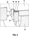
- Figure 4 shows an enlarged view of a section of Figure 3 .
- the Figure 4 enlarged section is in Figure 3 marked by a dashed border.
- the support disk 24 has an elastic damping element 25. It is also conceivable that the support disk 24 is designed to be elastic at least in some areas.
- the damping element 25 is arranged on a radial inner side 26 of the support disk 24.
- the damping element 25 is designed as a rubber coating 28. It is also conceivable that the support disk 24 can be designed to be elastic on its radial inner side 26. The support disk 24 can have a rubber coating 28 on its radial inner side 26.
- the shaft arrangement 10 comprises a retaining ring 30.
- a groove 32 is formed on the shaft 14, into which the retaining ring 30 engages.
- the retaining ring 30 secures the support disk 24 axially.
- the retaining ring 30 is arranged on a side of the support disk 24 facing away from the idler gear 16.
Landscapes
- Engineering & Computer Science (AREA)
- General Engineering & Computer Science (AREA)
- Mechanical Engineering (AREA)
- Physics & Mathematics (AREA)
- Electromagnetism (AREA)
- Gear Transmission (AREA)
Abstract
Die Erfindung betrifft eine Wellenanordnung (10) umfassend eine Welle (14) ein Losrad (16), ein Koppelelement (18), ein Kupplungselement (20), eine Stützscheibe (24) zum axialen Stützen des Losrads (16), wobei die Stützscheibe (24) axial benachbart zum Losrad (16) auf der Welle (14) angeordnet ist, wobei die Stützscheibe (24) ein elastisches Dämpfungselement (25) aufweist. Die Erfindung betrifft zudem eine Antriebsanordnung (12) mit einer solchen Wellenanordnung (10) und ein Fahrzeug mit einer solchen Antriebsanordnung (12).
Description
- Die Erfindung betrifft eine Wellenanordnung mit Merkmalen des Anspruchs 1, eine Antriebsanordnung mit Merkmalen des Anspruchs 8 und ein Fahrzeug mit Merkmalen des Anspruchs 10.
- In Getrieben finden Losräder Anwendung, welche an eine Welle an- oder abgekoppelt werden können. Diese Losräder weisen in der Regel eine Schrägverzahnung auf. Im angekoppelten Zustand werden sie je nach Lastrichtung (Schub oder Zug) axial in die eine oder andere Richtung gedrängt bzw. bewegt. Zur Abstützung bzw. Aufnahme der dabei wirkenden Axialkräfte werden Stützscheiben verwendet.
- Die Stützscheiben werden in der Regel mit einem axialen und radialen Spiel verbaut. Nachteilig dabei ist, dass wenn die Stützscheiben im abgekoppelten Betrieb (Schleppen / Schub) entlastet sind, diese zu Schwingungen angeregt werden und unerwünschte Geräusche verursachen können. Die Stützscheiben können alternativ auf die Welle aufgepresst werden. Dies ist aufgrund enger Toleranzen und der hierfür aufwändigen Montage/Demontage sehr kostspielig.
- Erfindungsgemäß wird eine Wellenanordnung, insbesondere für eine Antriebsanordnung, vorgeschlagen. Die Wellenanordnung umfasst eine Welle, ein Losrad und ein Koppelelement. Das Koppelelement ist drehfest mit dem Losrad gekoppelt. Das Koppelelement kann drehfest auf dem Losrad angeordnet sein. Die Wellenanordnung umfasst weiter ein Kupplungselement. Das Kupplungselement ist drehfest mit der Welle gekoppelt und entlang einer Axialrichtung zwischen einer gekoppelten Position und einer entkoppelten Position beweglich. In der gekoppelten Position ist das Losrad mit der Welle drehfest gekoppelt. In der entkoppelten Position ist das Losrad auf der Welle frei drehbar (bzw. von der Welle entkoppelt). Die Wellenanordnung umfasst weiter eine Stützscheibe zum axialen Stützen des Losrads (bzw. zur Aufnahme von axialen Kräften). Die Stützscheibe ist axial benachbart zum Losrad auf der Welle angeordnet. Die Stützscheibe weist ein elastisches Dämpfungselement auf. Das Dämpfungselement kann aus einem elastischen Material bestehen oder elastisches Material umfassen. Das elastische Material kann Gummi und/oder ein Elastomer sein. Die Stützscheibe kann zumindest abschnittsweise ein elastisches Dämpfungselement aufweisen. Die Stützscheibe kann zumindest teilweise elastisch ausgebildet sein.
- Hierdurch kann ein Schwingen der Stützscheibe und die damit verbundenen, unerwünschten Geräusche verhindert oder zumindest reduziert werden. Zudem kann die Stützscheibe einfach montiert bzw. demontiert werden. Ein Mehraufwand bei der Montage bzw. Demontage kann somit verhindert werden. Es ist eine Handmontage der Stützscheibe möglich. Ein Auffpressen der Stützscheibe auf die Welle ist nicht nötig. Damit kann mit einfachen und kostengünstigen Mitteln eine Stützscheibe zur Aufnahme von axialen Kräften eines Losrads bereitgestellt werden.
- Vorliegend ist mit "axial" bzw. "Axialrichtung" eine entlang der Mittellängsachse bzw. parallel zur Mittellängsachse der Welle ausgerichtete Richtung gemeint. Mit anderen Worten, die Mittellängsachse der Welle ist entlang der Axialrichtung orientiert. Entsprechend ist mit "radial" bzw. "Radialrichtung" eine senkrecht zur Mittellängsachse der Welle ausgerichtete und von der Mittellängsachse der Welle ausgehende Richtung gemeint.
- Gemäß einer Weiterbildung kann das Dämpfungselement an einer radialen Innenseite (bzw. dem Innenumfang) der Stützscheibe angeordnet sein. Das Dämpfungselement kann an der radialen Innenseite (bzw. dem Innenumfang) der Stützscheibe befestigt sein, bspw. durch Kleben. Die Stützscheibe kann an ihrer radialen Innenseite (bzw. dem Innenumfang) elastisch ausgebildet sein. Der Innendurchmesser der Stützscheibe und/oder des Dämpfungselements kann in einem unbelasteten Zustand geringer sein als der Außendurchmesser der Welle am Aufnahmeort des Dämpfungselements.
- Hierdurch ist eine einfache Handmontage der Stützscheibe möglich. Ein Schwingen der Stützscheibe, das insbesondere durch Vibrationen, die über die Welle an die Stützscheibe übertragen werden, verursacht wird, und die damit verbundenen, unerwünschten Geräusche können verhindert oder zumindest reduziert werden.
- Gemäß einer Weiterbildung kann das Dämpfungselement als eine Gummierung ausgebildet sein. Die Stützscheibe kann eine Gummierung aufweisen.
- Hierdurch können das Dämpfungselement bzw. eine teilweise elastische Stützscheibe mit einfachen Mitteln realisiert werden.
- Gemäß einer Weiterbildung kann die Wellenanordnung einen Sicherungsring umfassen. Der Sicherungsring kann in eine auf der Welle angeordnete Nut eingreifen. Der Sicherungsring kann eingerichtet sein, um die Stützscheibe axial zu sichern. Der Sicherungsring kann an einer von dem Losrad abgewandten Seite des Stützscheibe angeordnet sein.
- Hierdurch kann die Stützscheibe mit einfachen Mitteln axial gesichert werden.
- Gemäß einer Weiterbildung kann die Wellenanordnung eine Führungsnabe aufweisen. Die Führungsnabe kann mit der Welle drehfest gekoppelt sein. Die Führungsnabe kann auf der Welle angeordnet sein. Das Kupplungselement kann mittels der Führungsnabe mit der Welle drehfest gekoppelt sein.
- Hierdurch kann mit einfachen Mitteln eine sichere drehfeste Kopplung des Kupplungselements und damit des Losrads mit der Welle umgesetzt werden.
- Gemäß einer Weiterbildung kann die Wellenanordnung ein Zahnrad umfassen. Das Zahnrad kann als ein Festrad ausgebildet sein. Das Zahnrad kann mit der Welle drehfest gekoppelt sein. Das Zahnrad kann auf der Welle angeordnet sein. Das Zahnrad kann zur Kopplung der Welle eingerichtet sein. Das Zahnrad kann zur Drehmomentübertragung mittels der Welle dienen.
- Hierdurch kann mit einfachen Mitteln eine Kopplung der Welle zur Drehmomentübertragung umgesetzt werden.
- Gemäß einer Weiterbildung können die Führungsnabe und/oder das Zahnrad einstückig (bzw. einteilig) mit der Welle ausgebildet sein.
- Hierdurch kann eine robuste Wellenanordnung realisiert werden. Zudem kann die Herstellung einer derartigen Wellenanordnung vereinfacht werden. Des weiteren kann die Anzahl der Komponenten und damit die Komplexität der Wellenanordnung reduziert werden.
- Erfindungsgemäß wird eine Antriebsanordnung für ein Fahrzeug, insbesondere ein Kraftfahrzeug, mit einer Wellenanordnung gemäß obiger Ausführungen vorgeschlagen. Hinsichtlich der damit erzielbaren Vorteile wird auf die diesbezüglichen Ausführungen zur Wellenanordnung verwiesen. Zur weiteren Ausgestaltung der Antriebsanordnung können die im Zusammenhang mit der Wellenanordnung beschriebenen und/oder die nachfolgend noch erläuterten Maßnahmen dienen.
- Gemäß einer Weiterbildung kann die Antriebsanordnung eine Antriebswelle umfassen. Die Antriebswelle kann mit der Welle (drehfest) koppelbar oder gekoppelt sein. Bei der Welle kann es sich um eine Zwischenwelle der Antriebsanordnung handeln. Die Antriebsanordnung kann ein Differential mit einem Differentialrad umfassen. Das Differentialrad kann mit der Welle (drehfest), insbesondere mittels des Losrads, koppelbar oder gekoppelt sein. Die Antriebsanordnung kann mindestens eine Abtriebswelle umfassen. Die Abtriebswelle kann mit dem Differential, insbesondere mit dem Differentialrad, (drehfest) koppelbar oder gekoppelt sein. Die Antriebsanordnung kann zudem eine elektrische Maschine aufweisen. Die Antriebswelle kann mittels der elektrischen Maschine antreibbar sein. Die Antriebsanordnung kann bspw. als E-Achse ausgebildet sein oder Bestandteil einer E-Achse bilden.
- Hierdurch lässt sich mit einfachen Mitteln eine robuste Antriebsanordnung umsetzen.
- Erfindungsgemäß wird ein Fahrzeug, insbesondere ein Kraftfahrzeug, mit einer Antriebsanordnung gemäß obiger Ausführungen vorgeschlagen. Hinsichtlich der damit erzielbaren Vorteile wird auf die diesbezüglichen Ausführungen zur Antriebsanordnung verwiesen. Zur weiteren Ausgestaltung des Fahrzeugs können die im Zusammenhang mit der Antriebsanordnung beschriebenen und/oder die nachfolgend noch erläuterten Maßnahmen dienen.
- Nachfolgend werden Ausführungsformen der Erfindung unter Bezugnahme auf die beiliegenden Zeichnungen erläutert. Es zeigen schematisch:
- Figur 1
- eine Darstellung einer Antriebsanordnung mit einer Wellenanordnung;
- Figur 2
- eine perspektivische Ansicht der Wellenanordnung gemäß
Figur 1 ; - Figur 3
- eine Schnittdarstellung der Wellenanordnung gemäß
Figur 2 ; und - Figur 4
- eine vergrößerte Ansicht eines Ausschnitts aus
Figur 3 . - Die Antriebsanordnung trägt in
Figur 1 insgesamt das Bezugszeichen 12. Die Antriebsanordnung 12 ist vorliegend als E-Achse ausgebildet. Die Antriebsanordnung 12 kann zum Antrieb eines Fahrzeugs, insbesondere eines Kraftfahrzeugs, eingerichtet sein. Die Antriebsanordnung 12 umfasst eine elektrische Maschine 11 mit einer Antriebswelle 38 und einem Antriebszahnrad 39 (bzw. Antriebsritzel). Die Antriebsanordnung 12 umfasst eine Wellenanordnung 10, mit einer Welle 14, einem Losrad 16 und einem Zahnrad 36. Bei der Welle 14 handelt es sich vorliegend um eine Zwischenwelle der Antriebsanordnung 12. - Vorliegend ist das Antriebszahnrad 39 drehfest mit der Antriebswelle 38 gekoppelt, insbesondere auf der Antriebswelle 38 angeordnet. Das Zahnrad 36 ist vorliegend drehfest mit der Welle 14 gekoppelt, insbesondere auf der Welle 14 angeordnet. Das Antriebszahnrad 39 und das Zahnrad 36 kämmen miteinander. Die Welle 14 ist so trieblich mit der Antriebswelle 38 gekoppelt. Mit anderen Worten, die Welle 14 kann mittels der Antriebswelle 38 angetrieben werden.
- Das Losrad 16 kann in einem gekoppelten Zustand mit der Welle 14 drehfest gekoppelt werden. In einem entkoppelten Zustand kann das Losrad auf der Welle 14 frei drehbar sein (von der Welle 14 entkoppelt werden). Das Losrad 16 ist hierzu mittels Wälzlagern, bspw. Nadellagern, drehbar auf der Welle 14 gelagert.
- Die Antriebsanordnung 12 umfasst vorliegend ein Differential 40 mit einem Differentialrad 42. Das Differentialrad 42 bzw. das Differential 40 können mit der Welle 14 über das Losrad 16 gekoppelt werden. Die Antriebsanordnung 12 weist vorliegend zwei Abtriebswellen 44 auf, die mit dem Differential 40, insbesondere mit dem Differentialrad 42, drehfest koppelbar sind.
-
Figur 2 zeigt eine perspektivische Ansicht der Wellenanordnung 10 gemäßFigur 1 . Die Wellenanordnung 10 umfasst ein Koppelelement 18. Das Koppelelement 18 ist drehfest mit dem Losrad 16 gekoppelt. Vorliegend ist das Koppelelement 18 auf dem Losrad 16 angeordnet. Die Wellenanordnung 10 umfasst weiter ein Kupplungselement 20. Das Kupplungselement 20 ist drehfest mit der Welle 14 gekoppelt. Das Kupplungselement 20 ist entlang einer Axialrichtung 22 zwischen einer gekoppelten Position und einer entkoppelten Position beweglich. In der gekoppelten Position des Kupplungselements 20 ist das Losrad 16 mit der Welle 14 drehfest gekoppelt. In der entkoppelten Position des Kupplungselements 20 ist das Losrad 16 auf der Welle 14 frei drehbar. - Die Wellenanordnung 10 umfasst eine Stützscheibe 24 zum axialen Stützen des Losrads 16. Mit anderen Worten, die Stützscheibe 24 ist zum Aufnehmen axialer Kräfte eingerichtet. Die Stützscheibe 24 ist axial benachbart zum Losrad 16 auf der Welle 14 angeordnet.
-
Figur 3 zeigt eine Schnittdarstellung der Wellenanordnung 10 gemäßFigur 2 . Die Wellenanordnung 10 umfasst eine Führungsnabe 34. Die Führungsnabe 34 ist mit der Welle 14 drehfest gekoppelt. Vorliegend ist die Führungsnabe 34 auf der Welle 14 angeordnet. Das Kupplungselement 20 ist mittels der Führungsnabe 34 mit der Welle 14 drehfest gekoppelt. - Die Führungsnabe 34 weist vorliegend eine Außenverzahnung (nicht dargestellt) und das Kupplungselement 20 eine Innenverzahnung (nicht dargestellt) auf. Das Kupplungselement 20 ist drehfest auf der Führungsnabe 34 angeordnet, wobei die Innenverzahnung des Kupplungselements 20 und die Außenverzahnung der Führungsnabe 34 miteinander in Eingriff sind. Das Koppelelement 18 weist eine Außenverzahnung (nicht dargestellt) auf. In der gekoppelten, in
Figur 3 dargestellten, Position des Kupplungselements 20 ist die Innenverzahnung des Kupplungselements 20 und die Außenverzahnung des Koppelelements 18 miteinander in Eingriff. Wird das Kupplungselement 20 inFigur 3 nach rechts, entlang der Axialrichtung 22, in die entkoppelte Position bewegt, so sind die Innenverzahnung des Kupplungselements 20 und die Außenverzahnung des Koppelelements 18 nicht mehr miteinander in Eingriff. - Vorliegend ist die Welle 14, die Führungsnabe 34 und das Zahnrad 36 einstückig ausgebildet. Es ist ebenso denkbar, dass die Welle 14, die Führungsnabe 34 und das Zahnrad 36 jeweils als separate Bauteile ausgebildet sein können.
-
Figur 4 zeigt eine vergrößerte Ansicht eines Ausschnitts ausFigur 3 . Der inFigur 4 vergrößerte Ausschnitt, ist inFigur 3 mittels einer gestrichelten Umrandung markiert. Die Stützscheibe 24 weist ein elastisches Dämpfungselement 25 auf. Ebenso ist es denkbar, dass die Stützscheibe 24 zumindest bereichsweise elastisch ausgebildet ist. - Das Dämpfungselement 25 ist vorliegend an einer radialen Innenseite 26 der Stützscheibe 24 angeordnet. Das Dämpfungselement 25 ist vorliegend als eine Gummierung 28 ausgebildet. Ebenso ist es denkbar, dass die Stützscheibe 24 an ihrer radialen Innenseite 26 elastisch ausgebildet sein kann. Die Stützscheibe 24 kann an ihrer radialen Innenseite 26 eine Gummierung 28 aufweisen.
- Die Wellenanordnung 10 umfasst einen Sicherungsring 30. An der Welle 14 ist eine Nut 32 ausgebildet, in die der Sicherungsring 30 eingreift. Der Sicherungsring 30 sichert die Stützscheibe 24 axial. Der Sicherungsring 30 ist an einer dem Losrad 16 abgewandten Seite der Stützscheibe 24 angeordnet.
Claims (10)
- Wellenanordnung (10), insbesondere für eine Antriebsanordnung (12), wobei die Wellenanordnung (10) umfasst:- eine Welle (14),- ein Losrad (16),- ein Koppelelement (18), wobei das Koppelelement (18) drehfest mit dem Losrad (16) gekoppelt, insbesondere auf dem Losrad (16) angeordnet, ist,- ein Kupplungselement (20), wobei das Kupplungselement (20) drehfest mit der Welle (14) gekoppelt ist und entlang einer Axialrichtung (22) zwischen einer gekoppelten Position und einer entkoppelten Position beweglich ist, wobei in der gekoppelten Position das Losrad (16) mit der Welle (14) drehfest gekoppelt ist, wobei in der entkoppelten Position das Losrad (16) auf der Welle (14) frei drehbar ist,- eine Stützscheibe (24) zum axialen Stützen des Losrads (16), wobei die Stützscheibe (24) axial benachbart zum Losrad (16) auf der Welle (14) angeordnet ist,- wobei die Stützscheibe (24) ein elastisches Dämpfungselement (25) aufweist.
- Wellenanordnung (10) nach Anspruch 1, dadurch gekennzeichnet, dass das Dämpfungselement (25) an einer radialen Innenseite (26) der Stützscheibe (24) angeordnet ist.
- Wellenanordnung (10) nach dem voranstehenden Anspruch, dadurch gekennzeichnet, dass das Dämpfungselement (25) als eine Gummierung (28) ausgebildet ist.
- Wellenanordnung (10) nach einem der voranstehenden Ansprüche, dadurch gekennzeichnet, dass die Wellenanordnung (10) einen Sicherungsring (30) umfasst, der in eine Nut (32) in der Welle (14) eingreift, um die Stützscheibe (24) axial zu sichern.
- Wellenanordnung (10) nach einem der voranstehenden Ansprüche, dadurch gekennzeichnet, dass die Wellenanordnung (10) eine Führungsnabe (34) aufweist, wobei die Führungsnabe (34) mit der Welle (14) drehfest gekoppelt, insbesondere auf der Welle (14) angeordnet, ist, wobei das Kupplungselement (20) mittels der Führungsnabe (34) mit der Welle (14) drehfest gekoppelt ist.
- Wellenanordnung (10) nach einem der voranstehenden Ansprüche, dadurch gekennzeichnet, dass die Wellenanordnung (10) ein Zahnrad (36) umfasst, wobei das Zahnrad (36) mit der Welle (14) drehfest gekoppelt, insbesondere auf der Welle (14) angeordnet, ist.
- Wellenanordnung (10) nach Anspruch 5 und/oder 6, dadurch gekennzeichnet, dass die Führungsnabe (34) und/oder das Zahnrad (36) einstückig mit der Welle (14) ausgebildet sind.
- Antriebsanordnung (12) für ein Fahrzeug, insbesondere ein Kraftfahrzeug, mit einer Wellenanordnung (10) nach einem der voranstehenden Ansprüche.
- Antriebsanordnung (12) nach Anspruch 8, dadurch gekennzeichnet, dass es sich bei der Welle (14) um eine Zwischenwelle handelt und die Antriebsanordnung (12) umfasst:- eine Antriebswelle (38), wobei die Antriebswelle (38) mit der Welle (14) koppelbar oder gekoppelt ist,- ein Differential (40) mit einem Differentialrad (42), wobei das Differentialrad (42) mit der Welle (14), insbesondere mittels des Losrads (16) koppelbar oder gekoppelt ist,- insbesondere mindestens eine Abtriebswelle (44), wobei die Abtriebswelle (44) mit dem Differential (40), insbesondere mit dem Differentialrad (42), koppelbar oder gekoppelt ist.
- Fahrzeug, insbesondere Kraftfahrzeug, mit einer Antriebsanordnung (12) nach einem der beiden voranstehenden Ansprüche.
Applications Claiming Priority (1)
| Application Number | Priority Date | Filing Date | Title |
|---|---|---|---|
| DE102023202095.5A DE102023202095A1 (de) | 2023-03-09 | 2023-03-09 | Wellenanordnung, Antriebsanordnung und Fahrzeug |
Publications (1)
| Publication Number | Publication Date |
|---|---|
| EP4428386A1 true EP4428386A1 (de) | 2024-09-11 |
Family
ID=89854606
Family Applications (1)
| Application Number | Title | Priority Date | Filing Date |
|---|---|---|---|
| EP24156221.4A Pending EP4428386A1 (de) | 2023-03-09 | 2024-02-07 | Wellenanordnung, antriebsanordnung und fahrzeug |
Country Status (2)
| Country | Link |
|---|---|
| EP (1) | EP4428386A1 (de) |
| DE (1) | DE102023202095A1 (de) |
Citations (3)
| Publication number | Priority date | Publication date | Assignee | Title |
|---|---|---|---|---|
| FR2897404A1 (fr) * | 2006-02-16 | 2007-08-17 | Renault Sas | Dispositif d'arret axial d'un pignon fou de boite de vitesses et procede de montage d'un tel dispositif |
| DE102014213924A1 (de) * | 2014-07-17 | 2016-01-21 | Schaeffler Technologies AG & Co. KG | Lagereinrichtung für ein Kupplungssystem eines Kraftfahrzeugs |
| DE102021208600A1 (de) * | 2021-08-06 | 2023-02-09 | Robert Bosch Gesellschaft mit beschränkter Haftung | Verfahren zum Betreiben einer Antriebsanordnung, Antriebsanordnung und Fahrzeug |
-
2023
- 2023-03-09 DE DE102023202095.5A patent/DE102023202095A1/de active Pending
-
2024
- 2024-02-07 EP EP24156221.4A patent/EP4428386A1/de active Pending
Patent Citations (3)
| Publication number | Priority date | Publication date | Assignee | Title |
|---|---|---|---|---|
| FR2897404A1 (fr) * | 2006-02-16 | 2007-08-17 | Renault Sas | Dispositif d'arret axial d'un pignon fou de boite de vitesses et procede de montage d'un tel dispositif |
| DE102014213924A1 (de) * | 2014-07-17 | 2016-01-21 | Schaeffler Technologies AG & Co. KG | Lagereinrichtung für ein Kupplungssystem eines Kraftfahrzeugs |
| DE102021208600A1 (de) * | 2021-08-06 | 2023-02-09 | Robert Bosch Gesellschaft mit beschränkter Haftung | Verfahren zum Betreiben einer Antriebsanordnung, Antriebsanordnung und Fahrzeug |
Also Published As
| Publication number | Publication date |
|---|---|
| DE102023202095A1 (de) | 2024-09-12 |
Similar Documents
| Publication | Publication Date | Title |
|---|---|---|
| DE2919405C2 (de) | Getriebe | |
| DE102007053509A1 (de) | Getrieberad und Getriebe | |
| DE102007011895B4 (de) | Stirnraddiffernzial und Überlagerungsdifferenzial mit dem Stirnraddifferenzial | |
| DE102016219399A1 (de) | Planetenkoppelgetriebe | |
| WO2009118218A1 (de) | Einrichtung zur reduzierung von rasselgeräuschen in mehrstufenschaltgetrieben | |
| DE102019127242A1 (de) | Getriebe sowie Anordnung eines Getriebes und einer Elektromaschine | |
| WO2017008873A1 (de) | Anlaufscheibe zur axialen sicherung von wälzkörpern eines lagers und getriebe mit anlaufscheibe | |
| AT501915B1 (de) | Vorrichtung zur drehelastischen drehmomentübertragung zwischen einer welle und einem auf der welle gelagerten zahnrad | |
| DE102007062363A1 (de) | Schaltgetriebe | |
| DE102008000822B4 (de) | Einrichtung zur Reduzierung von Rasselgeräuschen in Stufengetrieben | |
| DE102023202095A1 (de) | Wellenanordnung, Antriebsanordnung und Fahrzeug | |
| DE102015011074A1 (de) | Getriebe mit zumindest einer Exzenterwelle | |
| DE102018205006A1 (de) | Zahnrad | |
| DE102018127942A1 (de) | Planetengetriebe | |
| DE102020200655B4 (de) | Dämpfungssystem für Zahnradgetriebe | |
| DE102019119780A1 (de) | Kupplungselement | |
| DE102018128799A1 (de) | Welle-Nabe-Verbindung für ein Getriebe mit einer Doppelkupplungsvorrichtung | |
| DE102017202418B4 (de) | Getriebeeinheit | |
| DE102012006633A1 (de) | Anordnung eines Maschinenelements auf einer Welle oder Achse sowie eine Welle oder Achse zur Fixierung eines Maschinenelements | |
| DE102024116898A1 (de) | Zahnrad für ein Kraftfahrzeuggetriebe mit Dämpfungseinheit, Getriebe und Kraftfahrzeug | |
| DE102022110702A1 (de) | Verzahnte Welle-Nabe-Verbindung eines Getriebes für einen elektromechanischen Achsantriebsstrang | |
| DE3212607A1 (de) | Zweistufiges planetengetriebe | |
| DE19727557B4 (de) | Differentialgetriebe mit federbelasteten Abtriebswellen | |
| DE102017216448B4 (de) | Verstellbare Stabilisatoranordnung | |
| DE102017202419A1 (de) | Getriebeeinheit |
Legal Events
| Date | Code | Title | Description |
|---|---|---|---|
| PUAI | Public reference made under article 153(3) epc to a published international application that has entered the european phase |
Free format text: ORIGINAL CODE: 0009012 |
|
| STAA | Information on the status of an ep patent application or granted ep patent |
Free format text: STATUS: THE APPLICATION HAS BEEN PUBLISHED |
|
| AK | Designated contracting states |
Kind code of ref document: A1 Designated state(s): AL AT BE BG CH CY CZ DE DK EE ES FI FR GB GR HR HU IE IS IT LI LT LU LV MC ME MK MT NL NO PL PT RO RS SE SI SK SM TR |
|
| STAA | Information on the status of an ep patent application or granted ep patent |
Free format text: STATUS: REQUEST FOR EXAMINATION WAS MADE |
|
| 17P | Request for examination filed |
Effective date: 20250311 |