EP4428014A1 - Verbesserte verbindung für fahrzeugrahmen von fahrzeugen des öffentlichen personenverkehrs - Google Patents
Verbesserte verbindung für fahrzeugrahmen von fahrzeugen des öffentlichen personenverkehrs Download PDFInfo
- Publication number
- EP4428014A1 EP4428014A1 EP24305284.2A EP24305284A EP4428014A1 EP 4428014 A1 EP4428014 A1 EP 4428014A1 EP 24305284 A EP24305284 A EP 24305284A EP 4428014 A1 EP4428014 A1 EP 4428014A1
- Authority
- EP
- European Patent Office
- Prior art keywords
- elements
- connection system
- frame
- walls
- wall
- Prior art date
- Legal status (The legal status is an assumption and is not a legal conclusion. Google has not performed a legal analysis and makes no representation as to the accuracy of the status listed.)
- Pending
Links
- 239000000463 material Substances 0.000 claims description 9
- 238000004026 adhesive bonding Methods 0.000 claims description 4
- 239000004033 plastic Substances 0.000 claims description 3
- 229920003023 plastic Polymers 0.000 claims description 3
- 230000037431 insertion Effects 0.000 claims 1
- 238000003780 insertion Methods 0.000 claims 1
- 238000003466 welding Methods 0.000 description 17
- 230000008878 coupling Effects 0.000 description 5
- 238000010168 coupling process Methods 0.000 description 5
- 238000005859 coupling reaction Methods 0.000 description 5
- 238000004519 manufacturing process Methods 0.000 description 5
- 238000000034 method Methods 0.000 description 3
- 229910000831 Steel Inorganic materials 0.000 description 2
- 238000010276 construction Methods 0.000 description 2
- 230000007797 corrosion Effects 0.000 description 2
- 238000005260 corrosion Methods 0.000 description 2
- 238000001962 electrophoresis Methods 0.000 description 2
- 239000003292 glue Substances 0.000 description 2
- 229910052751 metal Inorganic materials 0.000 description 2
- 239000002184 metal Substances 0.000 description 2
- 150000002739 metals Chemical class 0.000 description 2
- 239000010959 steel Substances 0.000 description 2
- JOYRKODLDBILNP-UHFFFAOYSA-N Ethyl urethane Chemical compound CCOC(N)=O JOYRKODLDBILNP-UHFFFAOYSA-N 0.000 description 1
- NIXOWILDQLNWCW-UHFFFAOYSA-N acrylic acid group Chemical group C(C=C)(=O)O NIXOWILDQLNWCW-UHFFFAOYSA-N 0.000 description 1
- 239000000956 alloy Substances 0.000 description 1
- 229910045601 alloy Inorganic materials 0.000 description 1
- 229910052782 aluminium Inorganic materials 0.000 description 1
- XAGFODPZIPBFFR-UHFFFAOYSA-N aluminium Chemical compound [Al] XAGFODPZIPBFFR-UHFFFAOYSA-N 0.000 description 1
- 230000015572 biosynthetic process Effects 0.000 description 1
- 230000001419 dependent effect Effects 0.000 description 1
- 239000000446 fuel Substances 0.000 description 1
- JEIPFZHSYJVQDO-UHFFFAOYSA-N iron(III) oxide Inorganic materials O=[Fe]O[Fe]=O JEIPFZHSYJVQDO-UHFFFAOYSA-N 0.000 description 1
- 238000012423 maintenance Methods 0.000 description 1
- 238000012986 modification Methods 0.000 description 1
- 230000004048 modification Effects 0.000 description 1
- 229920000642 polymer Polymers 0.000 description 1
- 229920002635 polyurethane Polymers 0.000 description 1
- 239000004814 polyurethane Substances 0.000 description 1
Images


Classifications
-
- B—PERFORMING OPERATIONS; TRANSPORTING
- B62—LAND VEHICLES FOR TRAVELLING OTHERWISE THAN ON RAILS
- B62D—MOTOR VEHICLES; TRAILERS
- B62D27/00—Connections between superstructure or understructure sub-units
- B62D27/02—Connections between superstructure or understructure sub-units rigid
- B62D27/023—Assembly of structural joints
Definitions
- the present invention concerns an improved connection for vehicular frame.
- the present invention finds its preferred, although not exclusive, application in public transport vehicles such as buses. Reference will be made to this application by way of example below.
- Public transport vehicles such as buses, and vehicle in generals, are provided with a frame/chassis that defines one of the structural portions of the vehicle.
- the bus chassis is realized via steel bars that are welded together to define a reticular structure defining the shape of the frame.
- Such frame usually defines a roof and a pair of lateral walls.
- also part of the pavement may be defined by the frame.
- welding may be realized only between the same or similar materials. Indeed, welding between different metals such as steel or aluminum is difficult or permissible by using very special techniques and alloys that increase exponentially manufacturing costs.
- welding is a complex and long operation and at least a minimum thickness of the elements to be welded is required in order to reduce risk of thermal deformation and to allow welding.
- This required thickness is however oversized with respect to structural needs of the frame, thereby increasing weight, cost and vehicular fuel consumption.
- Such frame 1' comprises a roof 2' and a pair of lateral walls 3' extending perpendicularly from roof 2'. Both roof 2' and walls 3' are realized via a reticular structure defined by a plurality of elements 4'. Making reference to figure 2 , the roof 2' is realized via a pair of longitudinal elements 5' realized substantially as single pieces extending all over the longitudinal axis A' of the frame 1'.
- Such pair of longitudinal elements 5' is connected on a direction transversal with respect to longitudinal axis A' by a plurality of transversal bars 6' that are spaced along longitudinal axis A' and by a plurality of inclined bars 7' crossing the longitudinal elements 5' and the transversal bars 6'.
- inclined bars 7' are places to define a plurality of rhombuses along axis A' direction.
- Further connection elements 8' are placed between the inclined bars 7' and the longitudinal elements 5' in order to strengthen the overall structure.
- An aim of the present invention is to satisfy the above mentioned needs in a cost-effective and optimized manner.
- Figure 3 discloses a frame 1 comprising a plurality of elements E connected in a reticular fashion via a connection system 10, 20 according to the invention and as described further in detail.
- Figures 4 and 5 disclose two alternative construction arrangements of a first embodiment of a connection system 10 for connecting the aforementioned different elements E of the aforementioned frame 1.
- connection system 10 comprises a pair of fixing masks 10', 10" connected together by fixing means 11 housed within openings 12 realized in fixing masks 10', 10''.
- Each pair of masks 10', 10'' comprises a main plate 10a and a pair of lateral walls 10b extending from at least part of the perimeter of the main plate 10a.
- the main plate 10a and the lateral walls 10b are shaped to allow the cooperation at contact with the peculiar geometric arrangement of walls of the elements E that needs to be connected together and defines the aforementioned openings 12.
- connection system 10 configured to allow the connection between four elements E, namely a main element Ea and three secondary elements Eb, Ec, Ed.
- the secondary elements Eb, Ec, Ed and the main element Ea are contained in the same plane and the secondary elements Eb, Ec, Ed extend getting away in different directions from the main element Ea.
- the main plate 10a of the embodiment of figure 4 have a main longitudinal portion configured to cooperate with the main element Ea and three secondary portions extending from the main longitudinal portion configured to cooperate with the secondary elements Eb, Ec, Ed.
- the lateral walls 10b extends from substantially all the perimeter of the main plate 10a except in corners where the lateral walls 10b are separated or joint by a joint portion 10c that is preferably curved.
- the openings 12 are realized on radial extremities of the masks 10', 10'' on each lateral wall 10b and the central plate 10a and linearly aligned one with the other both along a radial and a circumferential direction with respect to the center of mask 10', 10".
- connection system 10 configured to allow the connection between two elements E, namely a pair of elements Ef, Eg, connected at their extremities in an incident manner, e.g. perpendicular one to the other.
- each mask 10', 10" comprises a main plate 10a and a pair of lateral walls 10b having substantially the same function of the arrangement of figure 4 .
- the masks 10', 10" defines the openings 12 that are realized on each lateral wall 10b and the central plate 10a.
- the openings 12 and linearly aligned one with the other both along a radial and a circumferential direction with respect to the center of mask 10', 10".
- Figures 6 and 7 disclose two alternative construction arrangements of a second embodiment of a connection system 20 for connecting the aforementioned different elements E of the aforementioned frame 1.
- connection system 20 comprises a plurality of fixing masks 20', 20'', 20''' connected to elements E via gluing.
- Non limitative examples of gluing materials are epoxydic, acrylic, urethane, polyurethane, glues.
- Each fixing mask 20', 20", 20′′′ comprises at least a first wall 20a and a second wall 20b connected together in an incident manner, e.g. orthogonally and shaped to follow the geometric arrangement of the elements E connected together.
- the fixing masks 20', 20", 20′′′ may further comprise a joint portion 20c configured to connect a first and a second walls that are not connected into a perpendicular way one with respect to the other.
- the fixing masks 20', 20", 20′′′ may further comprise a third wall 20d incident with respect to at least one between the first and second walls 20a, 20b.
- Walls 20a, 20b, 20c are configured to cooperate at contact with the elements to be connected by interposition with the aforementioned glue.
- connection system 20 configured to allow the connection between three elements Ei, Eh, Ej via a three masks 20', 20'', 20''' shaped in order to allow the connection of the three elements as a "T" and a further connection system 20 configured to allow the connection between one of the aforementioned three elements Ej to three further elements El, Em, En that extends diverging one with respect to the other from the element Ej.
- Such further connection system 20 comprises four masks 20', 20′′′, 20′′′, 20 ⁇ configured to be fixed to different sides of the elements Ej, El, Em, En to allow their mutual fixation.
- Figure 7 discloses a connection system 20 configured to connect five elements Eo, Ep, Eq, Er, Es.
- Such connection system comprises three masks 20', 20", 20′′′ configured to surround different sides of the aforementioned five elements Eo, Ep, Eq, Er, Es to allow their mutual fixation.
- one of the masks 20' comprises three walls 20a, 20b, 20c and one of the masks 20′′′ has a first wall 20a that extends all over the five elements Eo, Ep, Eq, Er, Es.
- masks 10', 20' may have different shapes as exemplified in figures 8, 9 and 19 that discloses different shapes of bent masks 10', 20'.
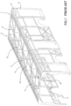
- connection system 10, 20 An example of frame 1 that can be arranged via connection system 10, 20 is shown in figure 3 . It is noticed that the frame 1 may constitute the support structure for a roof and side walls of a public transport vehicle, and, if necessary for front and rear wall thereof.
- Such frame 1 comprises a pair of longitudinal external side member 2 that are realized via a plurality of elements E connected together via connection system 10, 20.
- longitudinal external sides 2 are realized via elements E having different extensions along longitudinal axis A of the vehicle.
- the longitudinal external side members 2 are connected transversally along axis A, in particular perpendicularly, via a plurality of transversal bars 3 that are realized via a plurality of elements E connected together via connection system 10, 20.
- transversal bars 3 are realized via elements E having different extensions along the aforementioned transversal direction.
- Frame 1 further comprises a longitudinal inner bar 4 that extends parallel with respect to side members 2, transversally comprised between these latter and realized via a plurality of elements E connected together via connection system 10, 20.
- longitudinal inner bar 4 is realized via elements E having different extensions along longitudinal axis A of the vehicle.
- the frame 1 advantageously comprises inclined bars 5, 6 operatively connected between at least one among the transversal bars 3, the longitudinal side elements 2 and the inner longitudinal bar 4.
- Such inclined bars 5, 6 are generally realized as a single element E that is connected at its extremity to the aforementioned portions of the frame 1 via a connection system 10, 20.
- the inclined bars 5, 6 are disposed one to the other in order to define a plurality of rhombuses shape along longitudinal axis A.
- rhombuses may overall connect together the longitudinal side elements 2 via transversal bars 3 and the inner longitudinal bar 4 or merely connect together a plurality of transversal bars 3 and inner longitudinal bar 4.
- connection system 10, 20 the elements E may be realized in different materials, such as a polymeric material, e.g. plastic.
- a polymeric material e.g. plastic
- different plastic/polymers may be used in the same frame 1.
- connection system 10 20 in particular by posing masks 10', 20' shaped to follow the requested connection shape and fixing this latter by fixing means 11 or by gluing.
- connection system and a related frame according to the invention are apparent.
- connection system the welding between elements of which the frame is composed is avoided.
- connection system may be provided for different and complex geometries that could be welded with difficulty.
- the overall weight of the frame can be reduced.
- the depicted frame provided with elements with different lengths and materials can save about 50kg with respect to existing frames.
- the strength of the frame is the same of the existing ones or can be further increased due to the new and peculiar geometries that can be provided via such connection systems.
- the shape and number of masks of connection system may vary according to shape and number of elements to be connected together.
- Any material that allows sufficient mechanical strength for vehicular field can be used for masks and elements of the frame.
- the shape of the parts of the frame may vary within the limits of the below claims and clearly dimensions and number of elements of such frame are dependent to vehicle use and size.
Landscapes
- Engineering & Computer Science (AREA)
- Chemical & Material Sciences (AREA)
- Combustion & Propulsion (AREA)
- Transportation (AREA)
- Mechanical Engineering (AREA)
- Body Structure For Vehicles (AREA)
Applications Claiming Priority (2)
| Application Number | Priority Date | Filing Date | Title |
|---|---|---|---|
| IT102023000004041A IT202300004041A1 (it) | 2023-03-06 | 2023-03-06 | Connessione migliorata per telaio veicolare per veicolo per il trasporto pubblico |
| IT102023000004056A IT202300004056A1 (it) | 2023-03-06 | 2023-03-06 | Connessione migliorata per telaio veicolare per veicolo per il trasporto pubblico |
Publications (1)
| Publication Number | Publication Date |
|---|---|
| EP4428014A1 true EP4428014A1 (de) | 2024-09-11 |
Family
ID=90014361
Family Applications (1)
| Application Number | Title | Priority Date | Filing Date |
|---|---|---|---|
| EP24305284.2A Pending EP4428014A1 (de) | 2023-03-06 | 2024-02-21 | Verbesserte verbindung für fahrzeugrahmen von fahrzeugen des öffentlichen personenverkehrs |
Country Status (1)
| Country | Link |
|---|---|
| EP (1) | EP4428014A1 (de) |
Citations (5)
| Publication number | Priority date | Publication date | Assignee | Title |
|---|---|---|---|---|
| US3787130A (en) * | 1970-08-26 | 1974-01-22 | British Leyland Truck & Bus | Motor vehicle joint |
| EP0136264A2 (de) * | 1983-09-15 | 1985-04-03 | Alusuisse-Lonza Services Ag | Gerippe für einen Wagenkasten |
| JPH01132481U (de) * | 1988-03-04 | 1989-09-08 | ||
| JPH0731567U (ja) * | 1993-11-26 | 1995-06-13 | アラコ株式会社 | 車両用ボデーの骨格の補強構造 |
| KR19990006847U (ko) * | 1997-07-30 | 1999-02-25 | 양재신 | 버스 사이드 수직필러와 크로스 멤버의 마운팅 구조 |
-
2024
- 2024-02-21 EP EP24305284.2A patent/EP4428014A1/de active Pending
Patent Citations (5)
| Publication number | Priority date | Publication date | Assignee | Title |
|---|---|---|---|---|
| US3787130A (en) * | 1970-08-26 | 1974-01-22 | British Leyland Truck & Bus | Motor vehicle joint |
| EP0136264A2 (de) * | 1983-09-15 | 1985-04-03 | Alusuisse-Lonza Services Ag | Gerippe für einen Wagenkasten |
| JPH01132481U (de) * | 1988-03-04 | 1989-09-08 | ||
| JPH0731567U (ja) * | 1993-11-26 | 1995-06-13 | アラコ株式会社 | 車両用ボデーの骨格の補強構造 |
| KR19990006847U (ko) * | 1997-07-30 | 1999-02-25 | 양재신 | 버스 사이드 수직필러와 크로스 멤버의 마운팅 구조 |
Similar Documents
| Publication | Publication Date | Title |
|---|---|---|
| US12194838B2 (en) | Vehicle having a frame provided with a supporting structure for auxiliary units, in particular gas tanks or electric batteries | |
| EP2334539B1 (de) | Strukturverbindung für einen nutzfahrzeugrahmen und mit einer strukturverbindung hergestellter rahmen | |
| US7334828B2 (en) | Force strut brace | |
| JP2006513082A (ja) | 多用途自動車用前方フレーム部品 | |
| CN117241988A (zh) | 车辆车身 | |
| US6523885B2 (en) | Deformation member | |
| EP4428014A1 (de) | Verbesserte verbindung für fahrzeugrahmen von fahrzeugen des öffentlichen personenverkehrs | |
| US6641206B1 (en) | Load carrying arrangement for a vehicle | |
| CN114074713A (zh) | 车辆的车身顶部 | |
| JP2005271702A (ja) | 車体フレーム用サイドレール及びその製造方法 | |
| CN118202510A (zh) | 用于电池壳的横向构件以及电池壳 | |
| JP3053618B1 (ja) | 車両バンパーの補強部材 | |
| CN220391349U (zh) | 悬置安装结构和车辆 | |
| CN220391433U (zh) | 一种冲压车架及电动车 | |
| CN216840033U (zh) | 一种连接件及集成预应力扁钢带的增强型轻钢龙骨墙 | |
| CN118082985A (zh) | 汽车顶盖梁架、汽车顶盖总成和汽车 | |
| CN118544781A (zh) | 天窗框架组件和车辆 | |
| CN219487576U (zh) | 前轮罩总成及车辆 | |
| CN222820134U (zh) | 车架、车身及车辆 | |
| CN121469473A (zh) | 一种可拆卸防滚架总成及车身 | |
| CN223821806U (zh) | 前舱总成和车辆 | |
| CN212604354U (zh) | 一种车架组件总成和具有其的车辆 | |
| CN221947289U (zh) | 防护梁组件和车辆 | |
| CN218661295U (zh) | 车门外板支撑结构及汽车 | |
| CN211166769U (zh) | 防撞梁吸能盒、防撞梁组件和车辆 |
Legal Events
| Date | Code | Title | Description |
|---|---|---|---|
| PUAI | Public reference made under article 153(3) epc to a published international application that has entered the european phase |
Free format text: ORIGINAL CODE: 0009012 |
|
| STAA | Information on the status of an ep patent application or granted ep patent |
Free format text: STATUS: THE APPLICATION HAS BEEN PUBLISHED |
|
| AK | Designated contracting states |
Kind code of ref document: A1 Designated state(s): AL AT BE BG CH CY CZ DE DK EE ES FI FR GB GR HR HU IE IS IT LI LT LU LV MC ME MK MT NL NO PL PT RO RS SE SI SK SM TR |
|
| STAA | Information on the status of an ep patent application or granted ep patent |
Free format text: STATUS: REQUEST FOR EXAMINATION WAS MADE |
|
| 17P | Request for examination filed |
Effective date: 20250310 |