EP4427904A1 - Seat assembly, cushion, and tool and method of forming - Google Patents
Seat assembly, cushion, and tool and method of forming Download PDFInfo
- Publication number
- EP4427904A1 EP4427904A1 EP24161754.7A EP24161754A EP4427904A1 EP 4427904 A1 EP4427904 A1 EP 4427904A1 EP 24161754 A EP24161754 A EP 24161754A EP 4427904 A1 EP4427904 A1 EP 4427904A1
- Authority
- EP
- European Patent Office
- Prior art keywords
- tool
- blank
- cavity
- fluid
- apertures
- Prior art date
- Legal status (The legal status is an assumption and is not a legal conclusion. Google has not performed a legal analysis and makes no representation as to the accuracy of the status listed.)
- Pending
Links
- 238000000034 method Methods 0.000 title claims abstract description 27
- 239000012530 fluid Substances 0.000 claims abstract description 104
- 239000000463 material Substances 0.000 claims abstract description 48
- 238000004891 communication Methods 0.000 claims description 13
- 230000006870 function Effects 0.000 description 5
- 230000013011 mating Effects 0.000 description 5
- 230000004044 response Effects 0.000 description 4
- 238000007493 shaping process Methods 0.000 description 4
- 239000006260 foam Substances 0.000 description 3
- 229920010126 Linear Low Density Polyethylene (LLDPE) Polymers 0.000 description 2
- 239000007788 liquid Substances 0.000 description 2
- 238000002844 melting Methods 0.000 description 2
- 230000008018 melting Effects 0.000 description 2
- 229910000851 Alloy steel Inorganic materials 0.000 description 1
- 229920002430 Fibre-reinforced plastic Polymers 0.000 description 1
- 229920005830 Polyurethane Foam Polymers 0.000 description 1
- 230000001154 acute effect Effects 0.000 description 1
- 230000008859 change Effects 0.000 description 1
- 238000004590 computer program Methods 0.000 description 1
- 239000004744 fabric Substances 0.000 description 1
- 239000011151 fibre-reinforced plastic Substances 0.000 description 1
- 230000009477 glass transition Effects 0.000 description 1
- 239000008187 granular material Substances 0.000 description 1
- 238000010438 heat treatment Methods 0.000 description 1
- 238000003780 insertion Methods 0.000 description 1
- 230000037431 insertion Effects 0.000 description 1
- 239000010985 leather Substances 0.000 description 1
- 229920000092 linear low density polyethylene Polymers 0.000 description 1
- 239000004707 linear low-density polyethylene Substances 0.000 description 1
- 239000000155 melt Substances 0.000 description 1
- 239000012768 molten material Substances 0.000 description 1
- 239000008188 pellet Substances 0.000 description 1
- 210000004197 pelvis Anatomy 0.000 description 1
- 230000002093 peripheral effect Effects 0.000 description 1
- 229920003023 plastic Polymers 0.000 description 1
- 239000004033 plastic Substances 0.000 description 1
- 229920000642 polymer Polymers 0.000 description 1
- 239000011496 polyurethane foam Substances 0.000 description 1
- 239000007787 solid Substances 0.000 description 1
- 239000000758 substrate Substances 0.000 description 1
- 239000000725 suspension Substances 0.000 description 1
- 230000032258 transport Effects 0.000 description 1
- 210000000689 upper leg Anatomy 0.000 description 1
- 125000000391 vinyl group Chemical group [H]C([*])=C([H])[H] 0.000 description 1
- 229920002554 vinyl polymer Polymers 0.000 description 1
- XLYOFNOQVPJJNP-UHFFFAOYSA-N water Substances O XLYOFNOQVPJJNP-UHFFFAOYSA-N 0.000 description 1
Images


Classifications
-
- B—PERFORMING OPERATIONS; TRANSPORTING
- B29—WORKING OF PLASTICS; WORKING OF SUBSTANCES IN A PLASTIC STATE IN GENERAL
- B29C—SHAPING OR JOINING OF PLASTICS; SHAPING OF MATERIAL IN A PLASTIC STATE, NOT OTHERWISE PROVIDED FOR; AFTER-TREATMENT OF THE SHAPED PRODUCTS, e.g. REPAIRING
- B29C51/00—Shaping by thermoforming, i.e. shaping sheets or sheet like preforms after heating, e.g. shaping sheets in matched moulds or by deep-drawing; Apparatus therefor
- B29C51/26—Component parts, details or accessories; Auxiliary operations
- B29C51/42—Heating or cooling
- B29C51/421—Heating or cooling of preforms, specially adapted for thermoforming
- B29C51/424—Heating or cooling of preforms, specially adapted for thermoforming using a heated fluid
-
- B—PERFORMING OPERATIONS; TRANSPORTING
- B29—WORKING OF PLASTICS; WORKING OF SUBSTANCES IN A PLASTIC STATE IN GENERAL
- B29D—PRODUCING PARTICULAR ARTICLES FROM PLASTICS OR FROM SUBSTANCES IN A PLASTIC STATE
- B29D99/00—Subject matter not provided for in other groups of this subclass
- B29D99/0092—Producing upholstery articles, e.g. cushions, seats
-
- B—PERFORMING OPERATIONS; TRANSPORTING
- B68—SADDLERY; UPHOLSTERY
- B68G—METHODS, EQUIPMENT, OR MACHINES FOR USE IN UPHOLSTERING; UPHOLSTERY NOT OTHERWISE PROVIDED FOR
- B68G15/00—Auxiliary devices and tools specially for upholstery
-
- B—PERFORMING OPERATIONS; TRANSPORTING
- B29—WORKING OF PLASTICS; WORKING OF SUBSTANCES IN A PLASTIC STATE IN GENERAL
- B29C—SHAPING OR JOINING OF PLASTICS; SHAPING OF MATERIAL IN A PLASTIC STATE, NOT OTHERWISE PROVIDED FOR; AFTER-TREATMENT OF THE SHAPED PRODUCTS, e.g. REPAIRING
- B29C43/00—Compression moulding, i.e. applying external pressure to flow the moulding material; Apparatus therefor
- B29C43/006—Pressing and sintering powders, granules or fibres
-
- A—HUMAN NECESSITIES
- A47—FURNITURE; DOMESTIC ARTICLES OR APPLIANCES; COFFEE MILLS; SPICE MILLS; SUCTION CLEANERS IN GENERAL
- A47C—CHAIRS; SOFAS; BEDS
- A47C7/00—Parts, details, or accessories of chairs or stools
- A47C7/02—Seat parts
- A47C7/24—Upholstered seats
-
- A—HUMAN NECESSITIES
- A47—FURNITURE; DOMESTIC ARTICLES OR APPLIANCES; COFFEE MILLS; SPICE MILLS; SUCTION CLEANERS IN GENERAL
- A47C—CHAIRS; SOFAS; BEDS
- A47C7/00—Parts, details, or accessories of chairs or stools
- A47C7/36—Supports for the head or the back
- A47C7/40—Supports for the head or the back for the back
-
- B—PERFORMING OPERATIONS; TRANSPORTING
- B29—WORKING OF PLASTICS; WORKING OF SUBSTANCES IN A PLASTIC STATE IN GENERAL
- B29C—SHAPING OR JOINING OF PLASTICS; SHAPING OF MATERIAL IN A PLASTIC STATE, NOT OTHERWISE PROVIDED FOR; AFTER-TREATMENT OF THE SHAPED PRODUCTS, e.g. REPAIRING
- B29C33/00—Moulds or cores; Details thereof or accessories therefor
- B29C33/02—Moulds or cores; Details thereof or accessories therefor with incorporated heating or cooling means
-
- B—PERFORMING OPERATIONS; TRANSPORTING
- B29—WORKING OF PLASTICS; WORKING OF SUBSTANCES IN A PLASTIC STATE IN GENERAL
- B29C—SHAPING OR JOINING OF PLASTICS; SHAPING OF MATERIAL IN A PLASTIC STATE, NOT OTHERWISE PROVIDED FOR; AFTER-TREATMENT OF THE SHAPED PRODUCTS, e.g. REPAIRING
- B29C35/00—Heating, cooling or curing, e.g. crosslinking or vulcanising; Apparatus therefor
- B29C35/02—Heating or curing, e.g. crosslinking or vulcanizing during moulding, e.g. in a mould
- B29C35/04—Heating or curing, e.g. crosslinking or vulcanizing during moulding, e.g. in a mould using liquids, gas or steam
- B29C35/041—Heating or curing, e.g. crosslinking or vulcanizing during moulding, e.g. in a mould using liquids, gas or steam using liquids
-
- B—PERFORMING OPERATIONS; TRANSPORTING
- B29—WORKING OF PLASTICS; WORKING OF SUBSTANCES IN A PLASTIC STATE IN GENERAL
- B29C—SHAPING OR JOINING OF PLASTICS; SHAPING OF MATERIAL IN A PLASTIC STATE, NOT OTHERWISE PROVIDED FOR; AFTER-TREATMENT OF THE SHAPED PRODUCTS, e.g. REPAIRING
- B29C35/00—Heating, cooling or curing, e.g. crosslinking or vulcanising; Apparatus therefor
- B29C35/02—Heating or curing, e.g. crosslinking or vulcanizing during moulding, e.g. in a mould
- B29C35/04—Heating or curing, e.g. crosslinking or vulcanizing during moulding, e.g. in a mould using liquids, gas or steam
- B29C35/045—Heating or curing, e.g. crosslinking or vulcanizing during moulding, e.g. in a mould using liquids, gas or steam using gas or flames
-
- B—PERFORMING OPERATIONS; TRANSPORTING
- B29—WORKING OF PLASTICS; WORKING OF SUBSTANCES IN A PLASTIC STATE IN GENERAL
- B29C—SHAPING OR JOINING OF PLASTICS; SHAPING OF MATERIAL IN A PLASTIC STATE, NOT OTHERWISE PROVIDED FOR; AFTER-TREATMENT OF THE SHAPED PRODUCTS, e.g. REPAIRING
- B29C43/00—Compression moulding, i.e. applying external pressure to flow the moulding material; Apparatus therefor
- B29C43/02—Compression moulding, i.e. applying external pressure to flow the moulding material; Apparatus therefor of articles of definite length, i.e. discrete articles
-
- B—PERFORMING OPERATIONS; TRANSPORTING
- B29—WORKING OF PLASTICS; WORKING OF SUBSTANCES IN A PLASTIC STATE IN GENERAL
- B29C—SHAPING OR JOINING OF PLASTICS; SHAPING OF MATERIAL IN A PLASTIC STATE, NOT OTHERWISE PROVIDED FOR; AFTER-TREATMENT OF THE SHAPED PRODUCTS, e.g. REPAIRING
- B29C43/00—Compression moulding, i.e. applying external pressure to flow the moulding material; Apparatus therefor
- B29C43/32—Component parts, details or accessories; Auxiliary operations
- B29C43/36—Moulds for making articles of definite length, i.e. discrete articles
-
- B—PERFORMING OPERATIONS; TRANSPORTING
- B29—WORKING OF PLASTICS; WORKING OF SUBSTANCES IN A PLASTIC STATE IN GENERAL
- B29C—SHAPING OR JOINING OF PLASTICS; SHAPING OF MATERIAL IN A PLASTIC STATE, NOT OTHERWISE PROVIDED FOR; AFTER-TREATMENT OF THE SHAPED PRODUCTS, e.g. REPAIRING
- B29C43/00—Compression moulding, i.e. applying external pressure to flow the moulding material; Apparatus therefor
- B29C43/32—Component parts, details or accessories; Auxiliary operations
- B29C43/52—Heating or cooling
-
- B—PERFORMING OPERATIONS; TRANSPORTING
- B29—WORKING OF PLASTICS; WORKING OF SUBSTANCES IN A PLASTIC STATE IN GENERAL
- B29C—SHAPING OR JOINING OF PLASTICS; SHAPING OF MATERIAL IN A PLASTIC STATE, NOT OTHERWISE PROVIDED FOR; AFTER-TREATMENT OF THE SHAPED PRODUCTS, e.g. REPAIRING
- B29C43/00—Compression moulding, i.e. applying external pressure to flow the moulding material; Apparatus therefor
- B29C43/32—Component parts, details or accessories; Auxiliary operations
- B29C43/58—Measuring, controlling or regulating
-
- B—PERFORMING OPERATIONS; TRANSPORTING
- B29—WORKING OF PLASTICS; WORKING OF SUBSTANCES IN A PLASTIC STATE IN GENERAL
- B29C—SHAPING OR JOINING OF PLASTICS; SHAPING OF MATERIAL IN A PLASTIC STATE, NOT OTHERWISE PROVIDED FOR; AFTER-TREATMENT OF THE SHAPED PRODUCTS, e.g. REPAIRING
- B29C48/00—Extrusion moulding, i.e. expressing the moulding material through a die or nozzle which imparts the desired form; Apparatus therefor
- B29C48/001—Combinations of extrusion moulding with other shaping operations
- B29C48/0011—Combinations of extrusion moulding with other shaping operations combined with compression moulding
-
- B—PERFORMING OPERATIONS; TRANSPORTING
- B29—WORKING OF PLASTICS; WORKING OF SUBSTANCES IN A PLASTIC STATE IN GENERAL
- B29C—SHAPING OR JOINING OF PLASTICS; SHAPING OF MATERIAL IN A PLASTIC STATE, NOT OTHERWISE PROVIDED FOR; AFTER-TREATMENT OF THE SHAPED PRODUCTS, e.g. REPAIRING
- B29C48/00—Extrusion moulding, i.e. expressing the moulding material through a die or nozzle which imparts the desired form; Apparatus therefor
- B29C48/001—Combinations of extrusion moulding with other shaping operations
- B29C48/0022—Combinations of extrusion moulding with other shaping operations combined with cutting
-
- B—PERFORMING OPERATIONS; TRANSPORTING
- B29—WORKING OF PLASTICS; WORKING OF SUBSTANCES IN A PLASTIC STATE IN GENERAL
- B29C—SHAPING OR JOINING OF PLASTICS; SHAPING OF MATERIAL IN A PLASTIC STATE, NOT OTHERWISE PROVIDED FOR; AFTER-TREATMENT OF THE SHAPED PRODUCTS, e.g. REPAIRING
- B29C48/00—Extrusion moulding, i.e. expressing the moulding material through a die or nozzle which imparts the desired form; Apparatus therefor
- B29C48/25—Component parts, details or accessories; Auxiliary operations
- B29C48/30—Extrusion nozzles or dies
- B29C48/35—Extrusion nozzles or dies with rollers
-
- B—PERFORMING OPERATIONS; TRANSPORTING
- B29—WORKING OF PLASTICS; WORKING OF SUBSTANCES IN A PLASTIC STATE IN GENERAL
- B29C—SHAPING OR JOINING OF PLASTICS; SHAPING OF MATERIAL IN A PLASTIC STATE, NOT OTHERWISE PROVIDED FOR; AFTER-TREATMENT OF THE SHAPED PRODUCTS, e.g. REPAIRING
- B29C51/00—Shaping by thermoforming, i.e. shaping sheets or sheet like preforms after heating, e.g. shaping sheets in matched moulds or by deep-drawing; Apparatus therefor
- B29C51/002—Shaping by thermoforming, i.e. shaping sheets or sheet like preforms after heating, e.g. shaping sheets in matched moulds or by deep-drawing; Apparatus therefor characterised by the choice of material
- B29C51/004—Textile or other fibrous material made from plastics fibres
-
- B—PERFORMING OPERATIONS; TRANSPORTING
- B29—WORKING OF PLASTICS; WORKING OF SUBSTANCES IN A PLASTIC STATE IN GENERAL
- B29C—SHAPING OR JOINING OF PLASTICS; SHAPING OF MATERIAL IN A PLASTIC STATE, NOT OTHERWISE PROVIDED FOR; AFTER-TREATMENT OF THE SHAPED PRODUCTS, e.g. REPAIRING
- B29C51/00—Shaping by thermoforming, i.e. shaping sheets or sheet like preforms after heating, e.g. shaping sheets in matched moulds or by deep-drawing; Apparatus therefor
- B29C51/08—Deep drawing or matched-mould forming, i.e. using mechanical means only
- B29C51/082—Deep drawing or matched-mould forming, i.e. using mechanical means only by shaping between complementary mould parts
-
- B—PERFORMING OPERATIONS; TRANSPORTING
- B29—WORKING OF PLASTICS; WORKING OF SUBSTANCES IN A PLASTIC STATE IN GENERAL
- B29C—SHAPING OR JOINING OF PLASTICS; SHAPING OF MATERIAL IN A PLASTIC STATE, NOT OTHERWISE PROVIDED FOR; AFTER-TREATMENT OF THE SHAPED PRODUCTS, e.g. REPAIRING
- B29C51/00—Shaping by thermoforming, i.e. shaping sheets or sheet like preforms after heating, e.g. shaping sheets in matched moulds or by deep-drawing; Apparatus therefor
- B29C51/18—Thermoforming apparatus
-
- B—PERFORMING OPERATIONS; TRANSPORTING
- B29—WORKING OF PLASTICS; WORKING OF SUBSTANCES IN A PLASTIC STATE IN GENERAL
- B29C—SHAPING OR JOINING OF PLASTICS; SHAPING OF MATERIAL IN A PLASTIC STATE, NOT OTHERWISE PROVIDED FOR; AFTER-TREATMENT OF THE SHAPED PRODUCTS, e.g. REPAIRING
- B29C51/00—Shaping by thermoforming, i.e. shaping sheets or sheet like preforms after heating, e.g. shaping sheets in matched moulds or by deep-drawing; Apparatus therefor
- B29C51/26—Component parts, details or accessories; Auxiliary operations
- B29C51/42—Heating or cooling
- B29C51/421—Heating or cooling of preforms, specially adapted for thermoforming
-
- B—PERFORMING OPERATIONS; TRANSPORTING
- B29—WORKING OF PLASTICS; WORKING OF SUBSTANCES IN A PLASTIC STATE IN GENERAL
- B29C—SHAPING OR JOINING OF PLASTICS; SHAPING OF MATERIAL IN A PLASTIC STATE, NOT OTHERWISE PROVIDED FOR; AFTER-TREATMENT OF THE SHAPED PRODUCTS, e.g. REPAIRING
- B29C69/00—Combinations of shaping techniques not provided for in a single one of main groups B29C39/00 - B29C67/00, e.g. associations of moulding and joining techniques; Apparatus therefore
- B29C69/001—Combinations of shaping techniques not provided for in a single one of main groups B29C39/00 - B29C67/00, e.g. associations of moulding and joining techniques; Apparatus therefore a shaping technique combined with cutting, e.g. in parts or slices combined with rearranging and joining the cut parts
-
- B—PERFORMING OPERATIONS; TRANSPORTING
- B60—VEHICLES IN GENERAL
- B60N—SEATS SPECIALLY ADAPTED FOR VEHICLES; VEHICLE PASSENGER ACCOMMODATION NOT OTHERWISE PROVIDED FOR
- B60N2/00—Seats specially adapted for vehicles; Arrangement or mounting of seats in vehicles
- B60N2/62—Thigh-rests
-
- B—PERFORMING OPERATIONS; TRANSPORTING
- B60—VEHICLES IN GENERAL
- B60N—SEATS SPECIALLY ADAPTED FOR VEHICLES; VEHICLE PASSENGER ACCOMMODATION NOT OTHERWISE PROVIDED FOR
- B60N2/00—Seats specially adapted for vehicles; Arrangement or mounting of seats in vehicles
- B60N2/64—Back-rests or cushions
-
- B—PERFORMING OPERATIONS; TRANSPORTING
- B60—VEHICLES IN GENERAL
- B60N—SEATS SPECIALLY ADAPTED FOR VEHICLES; VEHICLE PASSENGER ACCOMMODATION NOT OTHERWISE PROVIDED FOR
- B60N2/00—Seats specially adapted for vehicles; Arrangement or mounting of seats in vehicles
- B60N2/70—Upholstery springs ; Upholstery
- B60N2/7017—Upholstery springs ; Upholstery characterised by the manufacturing process; manufacturing upholstery or upholstery springs not otherwise provided for
-
- B—PERFORMING OPERATIONS; TRANSPORTING
- B68—SADDLERY; UPHOLSTERY
- B68G—METHODS, EQUIPMENT, OR MACHINES FOR USE IN UPHOLSTERING; UPHOLSTERY NOT OTHERWISE PROVIDED FOR
- B68G7/00—Making upholstery
- B68G7/02—Making upholstery from waddings, fleeces, mats, or the like
-
- B—PERFORMING OPERATIONS; TRANSPORTING
- B29—WORKING OF PLASTICS; WORKING OF SUBSTANCES IN A PLASTIC STATE IN GENERAL
- B29C—SHAPING OR JOINING OF PLASTICS; SHAPING OF MATERIAL IN A PLASTIC STATE, NOT OTHERWISE PROVIDED FOR; AFTER-TREATMENT OF THE SHAPED PRODUCTS, e.g. REPAIRING
- B29C35/00—Heating, cooling or curing, e.g. crosslinking or vulcanising; Apparatus therefor
- B29C35/02—Heating or curing, e.g. crosslinking or vulcanizing during moulding, e.g. in a mould
- B29C35/04—Heating or curing, e.g. crosslinking or vulcanizing during moulding, e.g. in a mould using liquids, gas or steam
- B29C35/045—Heating or curing, e.g. crosslinking or vulcanizing during moulding, e.g. in a mould using liquids, gas or steam using gas or flames
- B29C2035/046—Heating or curing, e.g. crosslinking or vulcanizing during moulding, e.g. in a mould using liquids, gas or steam using gas or flames dried air
-
- B—PERFORMING OPERATIONS; TRANSPORTING
- B29—WORKING OF PLASTICS; WORKING OF SUBSTANCES IN A PLASTIC STATE IN GENERAL
- B29C—SHAPING OR JOINING OF PLASTICS; SHAPING OF MATERIAL IN A PLASTIC STATE, NOT OTHERWISE PROVIDED FOR; AFTER-TREATMENT OF THE SHAPED PRODUCTS, e.g. REPAIRING
- B29C35/00—Heating, cooling or curing, e.g. crosslinking or vulcanising; Apparatus therefor
- B29C35/02—Heating or curing, e.g. crosslinking or vulcanizing during moulding, e.g. in a mould
- B29C35/04—Heating or curing, e.g. crosslinking or vulcanizing during moulding, e.g. in a mould using liquids, gas or steam
- B29C35/045—Heating or curing, e.g. crosslinking or vulcanizing during moulding, e.g. in a mould using liquids, gas or steam using gas or flames
- B29C2035/047—Heating or curing, e.g. crosslinking or vulcanizing during moulding, e.g. in a mould using liquids, gas or steam using gas or flames other than air
- B29C2035/048—Heating or curing, e.g. crosslinking or vulcanizing during moulding, e.g. in a mould using liquids, gas or steam using gas or flames other than air inert gas
-
- B—PERFORMING OPERATIONS; TRANSPORTING
- B29—WORKING OF PLASTICS; WORKING OF SUBSTANCES IN A PLASTIC STATE IN GENERAL
- B29C—SHAPING OR JOINING OF PLASTICS; SHAPING OF MATERIAL IN A PLASTIC STATE, NOT OTHERWISE PROVIDED FOR; AFTER-TREATMENT OF THE SHAPED PRODUCTS, e.g. REPAIRING
- B29C37/00—Component parts, details, accessories or auxiliary operations, not covered by group B29C33/00 or B29C35/00
- B29C2037/90—Measuring, controlling or regulating
-
- B—PERFORMING OPERATIONS; TRANSPORTING
- B29—WORKING OF PLASTICS; WORKING OF SUBSTANCES IN A PLASTIC STATE IN GENERAL
- B29C—SHAPING OR JOINING OF PLASTICS; SHAPING OF MATERIAL IN A PLASTIC STATE, NOT OTHERWISE PROVIDED FOR; AFTER-TREATMENT OF THE SHAPED PRODUCTS, e.g. REPAIRING
- B29C43/00—Compression moulding, i.e. applying external pressure to flow the moulding material; Apparatus therefor
- B29C43/32—Component parts, details or accessories; Auxiliary operations
- B29C43/58—Measuring, controlling or regulating
- B29C2043/5816—Measuring, controlling or regulating temperature
-
- B—PERFORMING OPERATIONS; TRANSPORTING
- B29—WORKING OF PLASTICS; WORKING OF SUBSTANCES IN A PLASTIC STATE IN GENERAL
- B29C—SHAPING OR JOINING OF PLASTICS; SHAPING OF MATERIAL IN A PLASTIC STATE, NOT OTHERWISE PROVIDED FOR; AFTER-TREATMENT OF THE SHAPED PRODUCTS, e.g. REPAIRING
- B29C2793/00—Shaping techniques involving a cutting or machining operation
- B29C2793/0027—Cutting off
-
- B—PERFORMING OPERATIONS; TRANSPORTING
- B29—WORKING OF PLASTICS; WORKING OF SUBSTANCES IN A PLASTIC STATE IN GENERAL
- B29C—SHAPING OR JOINING OF PLASTICS; SHAPING OF MATERIAL IN A PLASTIC STATE, NOT OTHERWISE PROVIDED FOR; AFTER-TREATMENT OF THE SHAPED PRODUCTS, e.g. REPAIRING
- B29C2793/00—Shaping techniques involving a cutting or machining operation
- B29C2793/0081—Shaping techniques involving a cutting or machining operation before shaping
-
- B—PERFORMING OPERATIONS; TRANSPORTING
- B29—WORKING OF PLASTICS; WORKING OF SUBSTANCES IN A PLASTIC STATE IN GENERAL
- B29C—SHAPING OR JOINING OF PLASTICS; SHAPING OF MATERIAL IN A PLASTIC STATE, NOT OTHERWISE PROVIDED FOR; AFTER-TREATMENT OF THE SHAPED PRODUCTS, e.g. REPAIRING
- B29C33/00—Moulds or cores; Details thereof or accessories therefor
- B29C33/02—Moulds or cores; Details thereof or accessories therefor with incorporated heating or cooling means
- B29C33/04—Moulds or cores; Details thereof or accessories therefor with incorporated heating or cooling means using liquids, gas or steam
- B29C33/046—Moulds or cores; Details thereof or accessories therefor with incorporated heating or cooling means using liquids, gas or steam using gas
-
- B—PERFORMING OPERATIONS; TRANSPORTING
- B29—WORKING OF PLASTICS; WORKING OF SUBSTANCES IN A PLASTIC STATE IN GENERAL
- B29C—SHAPING OR JOINING OF PLASTICS; SHAPING OF MATERIAL IN A PLASTIC STATE, NOT OTHERWISE PROVIDED FOR; AFTER-TREATMENT OF THE SHAPED PRODUCTS, e.g. REPAIRING
- B29C33/00—Moulds or cores; Details thereof or accessories therefor
- B29C33/02—Moulds or cores; Details thereof or accessories therefor with incorporated heating or cooling means
- B29C33/04—Moulds or cores; Details thereof or accessories therefor with incorporated heating or cooling means using liquids, gas or steam
- B29C33/048—Moulds or cores; Details thereof or accessories therefor with incorporated heating or cooling means using liquids, gas or steam using steam
-
- B—PERFORMING OPERATIONS; TRANSPORTING
- B29—WORKING OF PLASTICS; WORKING OF SUBSTANCES IN A PLASTIC STATE IN GENERAL
- B29C—SHAPING OR JOINING OF PLASTICS; SHAPING OF MATERIAL IN A PLASTIC STATE, NOT OTHERWISE PROVIDED FOR; AFTER-TREATMENT OF THE SHAPED PRODUCTS, e.g. REPAIRING
- B29C33/00—Moulds or cores; Details thereof or accessories therefor
- B29C33/10—Moulds or cores; Details thereof or accessories therefor with incorporated venting means
-
- B—PERFORMING OPERATIONS; TRANSPORTING
- B29—WORKING OF PLASTICS; WORKING OF SUBSTANCES IN A PLASTIC STATE IN GENERAL
- B29K—INDEXING SCHEME ASSOCIATED WITH SUBCLASSES B29B, B29C OR B29D, RELATING TO MOULDING MATERIALS OR TO MATERIALS FOR MOULDS, REINFORCEMENTS, FILLERS OR PREFORMED PARTS, e.g. INSERTS
- B29K2023/00—Use of polyalkenes or derivatives thereof as moulding material
- B29K2023/04—Polymers of ethylene
- B29K2023/06—PE, i.e. polyethylene
- B29K2023/0608—PE, i.e. polyethylene characterised by its density
- B29K2023/0625—LLDPE, i.e. linear low density polyethylene
-
- B—PERFORMING OPERATIONS; TRANSPORTING
- B29—WORKING OF PLASTICS; WORKING OF SUBSTANCES IN A PLASTIC STATE IN GENERAL
- B29K—INDEXING SCHEME ASSOCIATED WITH SUBCLASSES B29B, B29C OR B29D, RELATING TO MOULDING MATERIALS OR TO MATERIALS FOR MOULDS, REINFORCEMENTS, FILLERS OR PREFORMED PARTS, e.g. INSERTS
- B29K2105/00—Condition, form or state of moulded material or of the material to be shaped
- B29K2105/06—Condition, form or state of moulded material or of the material to be shaped containing reinforcements, fillers or inserts
- B29K2105/08—Condition, form or state of moulded material or of the material to be shaped containing reinforcements, fillers or inserts of continuous length, e.g. cords, rovings, mats, fabrics, strands or yarns
-
- B—PERFORMING OPERATIONS; TRANSPORTING
- B29—WORKING OF PLASTICS; WORKING OF SUBSTANCES IN A PLASTIC STATE IN GENERAL
- B29K—INDEXING SCHEME ASSOCIATED WITH SUBCLASSES B29B, B29C OR B29D, RELATING TO MOULDING MATERIALS OR TO MATERIALS FOR MOULDS, REINFORCEMENTS, FILLERS OR PREFORMED PARTS, e.g. INSERTS
- B29K2105/00—Condition, form or state of moulded material or of the material to be shaped
- B29K2105/06—Condition, form or state of moulded material or of the material to be shaped containing reinforcements, fillers or inserts
- B29K2105/20—Inserts
- B29K2105/206—Meshes, lattices or nets
-
- B—PERFORMING OPERATIONS; TRANSPORTING
- B29—WORKING OF PLASTICS; WORKING OF SUBSTANCES IN A PLASTIC STATE IN GENERAL
- B29L—INDEXING SCHEME ASSOCIATED WITH SUBCLASS B29C, RELATING TO PARTICULAR ARTICLES
- B29L2031/00—Other particular articles
- B29L2031/30—Vehicles, e.g. ships or aircraft, or body parts thereof
-
- B—PERFORMING OPERATIONS; TRANSPORTING
- B29—WORKING OF PLASTICS; WORKING OF SUBSTANCES IN A PLASTIC STATE IN GENERAL
- B29L—INDEXING SCHEME ASSOCIATED WITH SUBCLASS B29C, RELATING TO PARTICULAR ARTICLES
- B29L2031/00—Other particular articles
- B29L2031/58—Upholstery or cushions, e.g. vehicle upholstery or interior padding
-
- B—PERFORMING OPERATIONS; TRANSPORTING
- B29—WORKING OF PLASTICS; WORKING OF SUBSTANCES IN A PLASTIC STATE IN GENERAL
- B29L—INDEXING SCHEME ASSOCIATED WITH SUBCLASS B29C, RELATING TO PARTICULAR ARTICLES
- B29L2031/00—Other particular articles
- B29L2031/771—Seats
Definitions
- Various embodiments relate to a tool and a method of forming a nonfoam cushion and associated seat assembly, and a nonfoam cushion and a seat assembly.
- One or more includes a function being performed by one element, a function being performed by more than one element, e.g ., in a distributed fashion, several functions being performed by one element, several functions being performed by several elements, or any combination of the above.
- first, second, etc. are, in some instances, used herein to describe various elements, these elements should not be limited by these terms. These terms are only used to distinguish one element from another.
- a first contact could be termed a second contact, and, similarly, a second contact could be termed a first contact, without departing from the scope of the various described embodiments.
- the first contact and the second contact are both contacts, but they are not the same contact.
- the term “if' is, optionally, construed to mean “when” or “upon” or “in response to determining” or “in response to detecting,” depending on the context.
- the phrase “if it is determined” or “if [a stated condition or event] is detected” is, optionally, construed to mean “upon determining” or “in response to determining” or “upon detecting [the stated condition or event]” or “in response to detecting [the stated condition or event],” depending on the context.
- controller may be provided as one or more controllers or control modules for the various components and systems.
- the controller and control system may include any number of controllers, and may be integrated into a single controller, or have various modules. Some or all of the controllers may be connected by a controller area network (CAN) or other system.
- CAN controller area network
- any controller, circuit, or other electrical device disclosed herein may include any number of microprocessors, integrated circuits, memory devices (e.g., FLASH, random access memory (RAM), read only memory (ROM), electrically programmable read only memory (EPROM), electrically erasable programmable read only memory (EEPROM), or other suitable variants thereof) and software which co-act with one another to perform operation(s) disclosed herein.
- any one or more of the electrical devices as disclosed herein may be configured to execute a computer-program that is embodied in a non-transitory computer readable medium that is programmed to perform any number of the functions as disclosed herein.
- a seat assembly 20 such as a vehicle seat assembly 20 is illustrated.
- the seat assembly 20 may be shaped and sized as a front row driver or passenger seat, a second, third, or other rear row seat, and may include bench-style seats as shown, bucket seats, or other seat styles.
- the seat assembly may be a non-stowable seat or a stowable seat that may be foldable and stowable in a cavity in the vehicle floor.
- the seat assembly 20 may be configured for use with other non-vehicle applications.
- the seat assembly 20 has a frame 22 or other support structure.
- the seat assembly has seat components, and these seat components include at least a seat bottom 24 and a seat back 26.
- the seat bottom 24 may be sized to receive a seated occupant to support a pelvis and thighs of the occupant.
- the seat back 26 may be sized to extend upright from the seat bottom 24 to support a back of the occupant.
- the seat assembly may additionally have a head restraint 27, with the head restraint 27 illustrated for an adjacent seat assembly only.
- the seat bottom 24 has a seat bottom cushion 28.
- the seat back 26 has a seat back cushion 30.
- the frame 22 may include wire suspension mats or other structure to support the cushions 28, 30.
- the frame 22 provides rigid structural support for the seat components, e.g. the seat bottom 24 and seat back 26, and may be provided as multiple frame members that are moveable relative to one another to provide adjustments for the seat assembly.
- the frame may be formed from a stamped steel alloy, a fiber reinforced polymer, or any suitable structural material.
- the frame 22 may further include a substrate, e.g. a panel, to support the associated cushion.
- trim covers 32 are used to cover the seat bottom cushion 28 and the seat back cushion 30, and provide a seating surface for the seat assembly 20.
- the vehicle seat assembly 20 is shown without a trim cover, and the adjacent seat assembly illustrates the trim cover 32.
- the trim cover 32 covers both of the cushions 28, 30.
- multiple trim covers are provided to cover the seat bottom cushion and the seat back cushion.
- the trim cover 32 may be formed from one or more panels of a fabric, leather, leatherette, vinyl, or other material.
- a seating cushion 40 is described in further detail below, and the description may similarly be applied to the seat bottom cushion 28 or the seat back cushion 30.
- the seating cushion 40 as described herein may additionally be used for other seating components, or for other vehicle interior components.
- the seating cushion 40 includes at least one nonfoam component or member 42.
- the seating cushion 40 is formed solely from the nonfoam component 42, such that the nonfoam component 42 provides all of the cushioning for the seat component between the frame 22 and the trim cover 32.
- the seating cushion 40 may be formed from a nonfoam component 42 as well as one or more foam components, such as a component formed from molded polyurethane foam, or other nonfoam components.
- the seating cushion 40 may have the nonfoam and foam components positioned to provide different regions of the cushion 40 for the seating component, e.g. a central region, and side bolster regions. By removing some or all of the traditional foam from the seating cushion 40, the seat assembly 20 may be provided with improved support and comfort, and reduced weight.
- the nonfoam component or member 42 of the seating cushion 40 is formed by a stranded mesh material, also known as an entangled three-dimensional filament structure.
- the stranded-mesh material is made from a polymeric mesh having a plurality of integrated polymeric strands.
- the stranded-mesh material may be made from, for example, a linear low density polyethylene (LLPDE) material, although other polymers and materials effective to provide the desired properties and functionality are contemplated.
- LLPDE linear low density polyethylene
- the stranded-mesh material may be formed using extruded filaments of linear low-density polyethylene (LLDPE) that are randomly entangled, bent, looped, or otherwise positioned and oriented, and directly bonded to each other to provide a porous mesh structure, an example of which is shown in a closer view in Figure 2 .
- LLDPE linear low-density polyethylene
- the cushion may be formed from a cushion blank 41, or stranded mesh material blank 41, of a stranded-mesh material member 42 that includes a first surface 44 and a second surface 46 positioned opposite to the first surface 44. Side surfaces 47, or edges, extend between the first and second surfaces 44, 46.
- the first surface 44 may be positioned on the seat assembly 20 to support an occupant of the seat assembly.
- the various surfaces 44, 46, 47 may be formed from a cushion blank via a system as described below, and may include various features such as recesses, trenches, channels, concave or convex surfaces, or other contours on the surfaces 44, 46, 47, or at the intersection of associated surfaces 44, 46, 47.
- the cushion blank 41 may include one or more slits 48, or cuts into the cushion blank 41 that are used with the system as described below to form various features or shapes in the cushion 40 from the blank 41.
- the cushion blank 41 may be formed from a consolidated filament structure that provides the stranded mesh material from which the cushion 40 and member 42 as described above is formed.
- Material stock such as solid granules or pellets of a plastic, such as a linear low-density polyethylene (LLDPE) may be fed from a hopper to an extruder.
- the extruder melts the material stock and transports it through a die plate.
- the material exits the extruder under pressure and in a molten state.
- the die plate extrudes the material into filaments via multiple small circular through holes or apertures through which the molten material passes such that a single filament is extruded from each die plate hole.
- the filaments fall from the die plate to a funnel to help consolidate or group the filaments into a more compact arrangement in which the filaments bend or loop and each filament contacts and bonds to at least one other filament.
- the consolidated filament structure then enters a fluid bath, such as a liquid tank to help temporarily support the consolidated filament structure, maintain the porosity and density, and cools the filaments from the outside to solidify them.
- the tank may be provided with various rollers and conveyors, and the consolidated filament structure may be cut to a desired sized and shape to form a cushion blank, e.g. using a cutting wheel, a water jet, or another technique.
- the cushion blank 41 is provided as a generally rectangular prism.
- the cushion blank 41 may be further cut prior to use with the system as described below in order to form one or more slots or slits 48.
- the cushion blank 41 may be cut to a blind depth, or partially through the blank 41, to form a slot 48.
- the cushion blank 41 may be further cut to a near-net shape based on the desired shape and size of the cushion 40, as well as the desired localized density properties of the cushion 40.
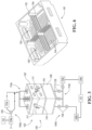
- Figure 3 illustrates a system 100 for shaping the cushion 40 from a cushion blank 41.
- a cushion blank 41 is positioned within the system 100 to shape the cushion blank 41 into the desired final shape and with the features, e.g. recesses, contours, etc., for the cushion 40.
- the cushion blank 41 is formed from a consolidated filament structure as described above after the material has been cooled and cut into blank form.
- the system 100 has a tool assembly 102.
- the tool assembly 102 is in fluid communication with one or more fluid systems 104.
- Each fluid system 104 has a fluid transfer device 106 such as a pump or fan, one or more valves 108, and a heater 110.
- the fluid system 104 may provide a flow of pressurized gas, such as air, or a liquid to the tool assembly 102, with the flow controller via a controller 112.
- the fluid system(s) 104 provide air to the tool assembly 102.
- the tool assembly 102 of the system 100 has a first tool 120 and a second tool 140.
- the first tool 120 has a first forming surface 122 defining a series of first apertures 124 therethrough.
- the second tool 140 has a second forming surface 142.
- the second forming surface 142 defines a series of second apertures 144 therethrough.
- the first and second forming surfaces 122, 142 cooperate to define a cavity 160 and shaped to form a cushion member from the blank 41.
- the cavity 160 is shaped to form various shapes into the cushion 40 from the blank 41, including concave, convex, or other complex shapes; channels, recesses, curves, chamfers, stepped corners or regions, or the like.
- the cavity 160 may further be sized to be smaller in volume than the blank 41, such that the tool assembly 102 compresses the blank 41 in the tool assembly, which may provide different localized densities in different regions in the cushion 40.
- the blank 41 may be oversized relative to the cavity 160.
- the variation in localized densities in the resulting cushion 40 may be advantageous, e.g. by providing an increased density in a thinner section or region.
- the first and second tools 120, 140 each define a portion of the apertures 124, 144 in the tool assembly forming surfaces 122, 142.
- the apertures 124, 144 in each of the first and second tools are illustrated as being circular; however, the apertures may be provided with other cross-sectional shapes.
- the apertures 124, 144 may be provided with a common diameter, or may be provided with varying diameters, e.g. to better control the flow to various regions of the cushion blank 41 in the tool assembly 102.
- the apertures 124, 144 may additionally be generally equally spaced from one another on the forming surfaces, or the spacing between the apertures may vary, likewise providing control over the flow to various regions of the cushion blank 41 in the tool assembly 102. In various examples, there may be certain regions of the forming surfaces 122, 142 that are provided without apertures.
- the first tool 120 has a mating surface 126 that cooperates with a corresponding mating surface 146 of the second tool 140 when the tool assembly 102 is closed.
- the first tool 120 may be translated or otherwise moved towards and away from the second tool 140 to open and close the tool assembly.
- the tool assembly 102 has a first fluid system 104a and a second fluid system 104b.
- first and second fluid systems 104a, 104b are illustrated and described differently with respect to one another, in other examples, two fluid systems 104a, two fluid systems 104b, or a single fluid system 104a, 104b may be used.
- the first fluid system 104a has a fluid transfer device 106a selectively connected to a heater 110a via a valve 108.
- the controller 112 controls the position of the valve 108 and the operation of the heater 110a to provide fluid to the first inlet manifold 114a and the first tool 120 as described below.
- the first inlet manifold 114a may further have valves 108 to selectively control flow through each of the manifold 114a lines, e.g. by controlling the flow rate.
- the inlet manifold 114a is fluidly connected to the first tool 120 and to the cavity 160 via the series of first apertures 124.
- the fluid system 104a is fluidly connected to the tool assembly 102 via the inlet manifold 114a.
- the inlet manifold 114a may provide more than one inlet port into the first tool 120 as shown, or may provide a single inlet.
- the second fluid system 104b has two fluid transfer devices 106b.
- One fluid device 106b is connected to a heater 110b, with the heater 110b connected to the inlet manifold 114b via a valve 108.
- the other fluid transfer device 106b is connected to the inlet manifold 114b by another valve 108.
- the controller 112 controls the position of the valves 108, fluid transfer devices 106b, and the heater 110b to provide fluid to the first inlet manifold 114b and the second tool 140 as described below.
- the first inlet manifold 114a may further have valves 108 to selectively control flow through each of the manifold 114a lines, e.g. by controlling the flow rate.
- the inlet manifold 114a is fluidly connected to the first tool 120 and to the cavity 160 via the series of first apertures 124.
- the fluid system 104a is fluidly connected to the tool assembly 102 via the inlet manifold 114a.
- the inlet manifold 114a may provide more than one inlet port into the first tool 120 as shown, or may provide a single inlet.
- various features of the fluid systems 104a, 104b may be combined, for example, with a single controller 112, or by using one fluid transfer device and/or heater to provide fluid flow to both manifolds 114a, 114, or the like.
- the interior of the first tool 120 and the second tool 140 may each form one or more chambers opposite to the forming surfaces 122, 142, with the associated apertures 124, 144 connecting the forming surface to the respective chamber(s).
- Figure 6 illustrates a view of the second tool 140 opposite to the forming surface 142, with the tool 140 having four chambers 150 divided by internal support walls 152.
- the internal support walls 152 provide structural support for the forming surface 142, and also may separate flow streams to maintain or control the uniformity of the flow.
- apertures 154 may be provided in the support walls 152 as shown to provide cross-flow between the chambers 150.
- the first tool 120 may be configured similarly to the second tool 140, with one or more support walls 152 forming multiple chambers 150 in the first tool.
- the inlet manifold 114 such as manifold 114a, 114b, may provide one or more inlet ports associated with each chamber 150 in the first tool and/or second tool 140. As such, the flow to different chambers 150 in the first tool and/or second tool 140, and different regions of the cavity 160 and blank 41 may be likewise controlled.
- the chambers 150 in the first and second tools may support various flow diverters, baffles, and other features to control the flow direction into or from the cavity 160 and through the blank 41.
- the tool assembly 102 is provided with one or more outlets 116 that are formed in the first tool 120, the second tool 140, or in both tools 120, 140.
- the outlets 116 fluidly connect and vent the cavity 160 to atmosphere either directly via the cavity 160 or via one of the chambers 150, and when air is the fluid in the systems 104, or may be connected to a return line to the fluid system(s) 104a, 104b for closed systems.
- the outlets 116 may be provided with a closure member 117, such as a baffle, plate, or valve.
- the closure member 117 may be further controlled, e.g. via the controller 112 between an open position to vent the cavity, or a closed position to retain or maintain fluid within the cavity 160.
- the closure members 117 may be closed or opened while the fluid transfer devices 106 and/or heaters 110 are being operated, e.g. to provide the desired temperature profile within the cavity 160.
- the tool assembly 102 is provided without closure members 117 such that the outlets(s) 116 are not closable.
- the tool assembly 102 is provided without defined outlet ports 116, and the tool assembly 102 may vent via various gaps or spaces between the mating surfaces 126, 146. The fluid flows from each fluid system 104a, 104b, into their respective inlet manifolds 114a, 114b, into the cavity 160, and then to the outlet(s) 116.
- the tool assembly 102 is provided with a single fluid system 114a or 114b, and a single outlet 116 in place of the other inlet manifold 114b, 114a, such that fluid flows sequentially from one inlet manifold, through both tools 120, 140, and to an outlet 116 sequentially.
- the fluid may flow sequentially in the assembly 102 from the inlet manifold 114, into the chambers 150 in the first tool 120, through the first series of apertures 124, through the cavity 160 and blank 41, through the series of second apertures 144, into the chambers 150 in the second tool 140, and to the outlet 116.
- the fluid may be at various temperatures to control the shaping of the blank 41.
- the fluid flow into the inlet manifold 114 flows through the series of first apertures 124 in the first tool, through the stranded mesh material of the blank 41, through the series of second apertures 144 in the second tool, and to the outlet 116.
- the fluid therefore convectively heats or cools the filaments and strands internally in the blank 41, as well as the strands along the outer surfaces of the blank 41.
- the first tool 120 and/or the second tool 140 may be provided with or more locating members 170 extending outwardly from the respective forming surface 122, 142.
- the second tool 140 has a plurality of locating members 170 provided as pins.
- the locating features 170 may be used to position the blank and retain the blank 41 in the desired position on the tool before and while the tool assembly is closed. As the blank 41 is a filament structure, the pins 170 easily extend into the blank 41 and between the filaments when locating the blank on the tool.
- the locator pins 170 may optionally be retractable such that they are retracted when the tool assembly is opened to facilitate removal of the cushion 40.
- the forming surface 122 and/or the forming surface 142 may be provided with one or more protrusions 180 to form a corresponding channel, recess, pocket, or other concave region in the cushion 40 from the blank 41.
- the blank 41 may be cut in a location corresponding to the protrusion prior to inserting the blank into the tool assembly.
- the blank 41 may be cut with a blind cut or slit 48 to provide relief and reduce gaps, warp, or distortion adjacent to the channel in the resulting cushion 40.
- blank 41 may be cut with a blind cut or slit 48 along the outer perimeter of the recess to provide relief and reduce gaps or warp adjacent to the recess in the resulting cushion 40 as the protruding forming surface 180 presses the blank material in the recessed region.
- other types of cuts may be provided such as a planar cut, a curved cut, or another complex geometry cut as a part of a through cut or a partial cut into the blank 41.
- These protrusions 180 may further provide locating features or members for the tool assembly 102.
- the system 100 also has a controller 112.
- the controller 112 is configured to control the fluid transfer device(s) 106, the valves 108, and the heater(s) 110 to selectively fluidly couple the heater 110 to the inlet manifold 114 to provide fluid to the cavity 160 at a first temperature, and selectively fluidly decouple the inlet manifold 114 from the heater 110 to provide fluid to the cavity 160 at a second temperature less than the first temperature.
- the controller 112 may control the position of the closure members 117 to retain fluid within the cavity 160 or vent the cavity.
- the controller 112 may close the closure members 117 when providing fluid at the first temperature, and open the closure members 117 when providing fluid at the second temperature, or vice versa.
- the controller 112 may further at least partially open or at least partially close the closure members 117 while providing fluid at the first temperature and/or second temperature to control the temperature profile within the cavity 160.
- the system 100 may have various sensors, such as temperature sensors, for use in controlling the flow through the tool assembly 102.
- the first and second temperatures may be set based on a softening temperature of the material for the filaments of the blank 41. In one example, the first temperature is set at an offset above the softening temperature, e.g. twenty to thirty degrees Celsius above the softening temperature.
- the second temperature is set at an offset below the softening temperature, and may be provided at ambient temperature.
- the controller 112 may further control the time that the fluid is provided into the cavity 160 at the first temperature, the time that the fluid is provided to the cavity 160 at the second temperature, the flow rate of the fluid, and/or the ramp on the temperature of the fluid in order to further control the shaping process for the blank 41.
- the controller 112 may additionally control valves 108 on individual lines in the inlet manifold 114 to control flow to various chambers 150 in the tools 120, 140, and to different regions of the cavity 160.
- the softening temperature may refer to the glass transition temperature of the material, and be less than the melting point, thereby allowing the filaments to soften and change shape of the filament and the blank 41, without completely melting the filaments and losing the overall filament structure and porosity in the blank 41 and resulting cushion.
- a method for use with the system 100 and controller 112 and to form a cushion 40 from a cushion blank 41 or a stranded mesh material blank 41.
- the blank is inserted into a cavity 160 of a tool assembly 102 shaped to form a cushion member.
- the first tool 120 is moved relative to the second tool 140 of the tool assembly after the blank is inserted into the cavity to close the tool assembly with the blank inside.
- the blank 41 may be compressed by the first and second tools 120, 140 as the size of the blank 41 may be larger than the cavity 160, e.g. the volume of the blank may be greater than the volume of the cavity.
- the blank 41 may be compressed to different degrees in different regions based on the size and shape of the blank 41 relative to the size and shape of the cavity 160.
- a corresponding protrusion 180 of the forming surface is inserted into the slot of the blank when inserting the blank into the cavity 160 of the tool assembly.
- the tools 120, 140 may be preheated prior to insertion of the blank 41 into the tool assembly, or any heating to the tools 120, 140 may occur only after the blank 41 is inserted via the fluid flow at the first temperature.
- the controller 112 operates the fluid transfer device(s) 106, the valves 108, and the heater(s) 110 to circulate fluid above a first temperature threshold into the inlet manifold 114 and through a series of apertures 124 defined in a forming surface 122 of the tool assembly and into the cavity 160 thereby softening the blank 41 and conforming a shape of the blank to the forming surfaces 122, 142.
- the controller 112 may further control any closure members 117, e.g. to a closed position to generally retain fluid within the cavity 160, and/or to an open position to vent the cavity 160.
- the controller 112 then controls the fluid transfer device 106, the valves 108, and the heater 110 to circulate the fluid below a second temperature threshold through the series of apertures 124 in the forming surfaces 122 and into the cavity 160 thereby setting the shape of the blank 41 to the forming surfaces 122, 142 and forming a cushion member.
- the first temperature threshold is greater than a softening temperature of the blank 41
- the second temperature threshold is less than a softening temperature of the blank 41.
- the fluid may be provided to the tool assembly at an ambient temperature during the third step.
- the controller 112 may further control any closure members 117, e.g. to an open position to generally vent fluid within the cavity 160, and/or to a closed position.
- the second step may be a first temperature cycle for the blank 41 to soften and shape the blank 41 to the shape defined by the forming surfaces
- the third step may be a second temperature cycle for the blank to set the shape of the blank 41.
- the first, second, and third steps may be performed sequentially.
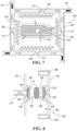
- a tool assembly 200 is illustrated schematically according to another embodiment.
- the tool assembly 200 may be used in place of the tool assembly 102 and with the system 100 of Figure 3 and generally according to the method, as described above. Elements that are the same as or similar to those described above may not be described with respect to Figures 7-8 for simplicity.
- Figure 7 illustrates a top schematic view of the tool assembly 200
- Figure 8 illustrates a side schematic view of the tool assembly 200 in an open position.
- the tool assembly 200 has a first tool 220 and a second tool 240.
- the first tool 220 and the second tool 240 are each positioned within a central region of a common chamber 202. Each of the first and second tools 220, 240 may be supported by standoffs or other support members 204 within the chamber 202.
- the first tool 220 has a first forming surface 222 defining a series of first apertures 224 therethrough.
- the second tool 240 has a second forming surface 242 defining a series of second apertures 244 therethrough.
- the first and second forming surfaces 222, 242 cooperate to define a cavity 260 shaped to form a cushion from a cushion blank 41.
- the first tool 220 has a mating surface 226 that mates with a corresponding mating surface 246 of the second tool when the tool assembly 200 is closed.
- the first tool 220 may be translated or otherwise moved towards and away from the second tool 240 to open and close the tool assembly.
- the chamber 202 has at least one inlet 206 in fluid communication with the circumferential inlet manifold 208 in fluid communication with a fluid system, such as fluid system 104a or 104b.
- the inlet manifold 208 extends about an outer peripheral of the chamber 202, or along at least a portion of the outer perimeter of the chamber.
- the inlet(s) 206 from the inlet manifold 208 to the chamber 202 is provided along the outer perimeter wall of the chamber.
- the circumferential inlet manifold 208 may receive fluid from the inlet manifold 114 via ports 210, or may be a part of the inlet manifold.
- the chamber has a single inlet 206; however, other numbers of inlets 206 are also contemplated.
- the circumferential inlet manifold 208 may receive flow from a single port 210 or from multiple ports 210 as shown.
- the inlet 206 may have an associated deflector 212.
- the deflector may extend into the circumferential inlet manifold 208 at an angle in order to help direct from the manifold 208 with the desired flow angle.
- the inlet 206 may further be formed with walls that are angled relative to the adjacent circumferential flow manifold 208 and with respect to the direction of fluid flow therein, as shown in Figure 7 .
- the deflector 212 and the angle of the inlet 206 are at forty-five degrees, although other acute angles are also contemplated.
- only one inlet 206 is shown, multiple inlets 206 and deflectors are contemplated, with the inlets 206 spaced along the circumferential manifold 208 to assist in created a vortex flow or circular flow within the chamber 202.
- the chamber 202 also defines an outlet 214.
- the outlet 214 is positioned to fluidly connect the central region of the chamber 202 to atmosphere such that fluid circulates radially inward within the chamber 202 from the inlet(s) 206 along the outer perimeter of the chamber 202 (and from the circumferential inlet manifold 208) to the outlet 214. This generally provides a vortex flow geometry within the chamber 202.
- the tool assembly 200 may be positioned in the system 100 and controlled via controller 112 according to a method as described above.
- the fluid flows sequentially in the assembly 102 from the inlet manifold 114, circumferential manifold 208, through the inlets 206 and into the chamber 202, and then has a vortex or circular flow path towards the tools 220, 240.
- the fluid flows through the apertures 224, 244 in the tools 220, 240 and through the cavity 160 and blank 41, and to the outlet 214.
- the fluid may be at various temperatures to control the shaping of the blank 41.
- the fluid flow into the inlet manifold 114 flows through the series of first apertures 124 in the first tool, through the stranded mesh material of the blank 41, through the series of second apertures 144 in the second tool, and to the outlet 116.
- the fluid therefore convectively heats or cools the filaments and strands internally in the blank 41, as well as the strands along the outer surfaces of the blank 41.
- a method is provided and a stranded mesh material blank is inserted into a cavity of a tool assembly shaped to form a cushion member. Fluid is circulated above a first temperature threshold through a series of apertures defined in a forming surface of the tool assembly and into the cavity thereby softening the blank and conforming a shape of the blank to the forming surface. Fluid is circulated below a second temperature threshold through the series of apertures in the forming surface and into the cavity thereby setting the shape of the blank to the forming surface and forming a cushion member.
- Clause 2 The method of clause 1 further comprising moving a first tool of the tool assembly relative to a second tool of the tool assembly after the stranded mesh material blank is inserted into the cavity.
- Clause 3 The method of clause 2 wherein the first tool defines a first portion of the series of apertures, and wherein the second tool defines a second portion of the series of apertures.
- Clause 4 The method of clause 2 further comprising compressing the stranded mesh material blank by moving the first tool relative to the second tool.
- Clause 5 The method of any one of clauses 1-4 further comprising cutting a slot in the stranded mesh material blank to a blind depth prior to inserting the blank into the cavity of the tool assembly, and inserting a protrusion of the forming surface into the slot of the blank when inserting the blank into the cavity of the tool assembly.
- Clause 6 The method of any one of clauses 1-5 wherein the first temperature threshold is greater than a softening temperature of the blank, and wherein the second temperature threshold is less than a softening temperature of the blank.
- Clause 7 The method of any one of clauses 1-6 further comprising forming the stranded mesh material member blank as a polymeric mesh having a plurality of integrated polymeric strands.
- Clause 8 The method of clause 7 further comprising forming the stranded mesh material member by extruding material through a die, funneling the extruded material from the die through a funnel, and moving the extruded material after the funnel via one or more rollers; and cutting the stranded mesh material blank after forming and prior to inserting the blank into the cavity of the tool assembly.
- a cushion for a seat assembly comprising a stranded mesh material member formed by the method of clause 8.
- a system is provided with a first tool comprising a first forming surface defining a series of first apertures therethrough, and a second tool comprising a second forming surface defining a second series of apertures therethrough, with the first and second forming surfaces cooperating to define a cavity and shaped to form a cushion member.
- An inlet manifold is fluidly connected to the cavity via at least one of the series of first apertures or the series of second apertures.
- Clause 11 The system of clause 10 wherein the first tool defines one or more first chambers in fluid communication with the inlet manifold, the one or more first chambers in fluid communication with the cavity via the series of first apertures in the first forming surface.
- Claim 12 The system of clause 10 or 11 wherein the inlet manifold is a first inlet manifold supported by the first tool and fluidly connected to the cavity via the series of first apertures, and wherein the system further comprises a second inlet manifold supported by the second tool and fluidly connected to the cavity via the second series of apertures.
- Clause 13 The system of any one of clauses 10-12 further comprising an outlet fluidly coupled to the inlet manifold via the series of first apertures and the cavity.
- Clause 15 The system of clause 13 wherein the first tool and the second tool are positioned within a central region of a chamber, the chamber having at least one inlet in fluid communication with the inlet manifold, and defining the outlet.
- Clause 16 The system of clause 15 wherein the inlet manifold extends along at least a portion of an outer perimeter wall of the chamber, the inlet is positioned along the outer perimeter wall of the chamber; and the outlet is positioned to fluidly connect the central region of the chamber to atmosphere such that fluid circulates radially inward within the chamber from the inlet to the outlet.
- Clause 17 The system of clause 16 wherein the inlet further comprises a deflector positioned to extend into the inlet manifold and direct fluid into the chamber.
- Clause 18 The system of any one of clauses 10-17 further comprising one or more locating members extending outwardly from the first forming surface and/or the second forming surface.
- a system is provided with a first tool comprising a first forming surface defining a series of first apertures therethrough, and a second tool comprising a second forming surface defining a series of second apertures therethrough, with the first and second forming surfaces cooperating to define a cavity and shaped to form a cushion member.
- One or more inlet manifolds are provided.
- a fluid system is provided with a fluid transfer device, a valve, and a heater in fluid communication with the inlet manifold.
- a controller is configured to control the valve to selectively fluidly couple the heater to the inlet manifold to provide fluid to the cavity at a first temperature, and selectively fluidly decouple the inlet manifold from the heater to provide fluid to the cavity at a second temperature less than the first temperature.
Landscapes
- Engineering & Computer Science (AREA)
- Mechanical Engineering (AREA)
- Manufacturing & Machinery (AREA)
- Aviation & Aerospace Engineering (AREA)
- Transportation (AREA)
- Health & Medical Sciences (AREA)
- Physics & Mathematics (AREA)
- Oral & Maxillofacial Surgery (AREA)
- Thermal Sciences (AREA)
- Textile Engineering (AREA)
- Mattresses And Other Support Structures For Chairs And Beds (AREA)
- Moulds For Moulding Plastics Or The Like (AREA)
- Extrusion Moulding Of Plastics Or The Like (AREA)
Abstract

Description
- Various embodiments relate to a tool and a method of forming a nonfoam cushion and associated seat assembly, and a nonfoam cushion and a seat assembly.
-
-
FIGURE 1 illustrates a perspective view of a seat assembly according to an embodiment; -
FIGURE 2 illustrates a partial view a cushion member according to an embodiment and for use with the seat assembly ofFigure 1 ; -
FIGURE 3 illustrates a schematic view of a system according to an embodiment; -
FIGURE 4 illustrates a perspective view of a first tool for use with the system ofFigure 3 ; -
FIGURE 5 illustrate a perspective view of a second tool for use with the system ofFigure 3 ; -
FIGURE 6 illustrates another perspective view of the first or second tool ofFigures 4-5 ; -
FIGURE 7 illustrates a top schematic view of a system according to another embodiment in a closed position; and -
FIGURE 8 illustrates a side schematic view of the system ofFigure 7 in an open position. - Reference will now be made in detail to embodiments, examples of which are illustrated in the accompanying drawings. In the following detailed description, numerous specific details are set forth in order to provide a thorough understanding of the various described embodiments. However, it will be apparent to one of ordinary skill in the art that the various described embodiments may be practiced without these specific details. In other instances, well-known methods, procedures, components, circuits, and networks have not been described in detail so as not to unnecessarily obscure aspects of the embodiments.
- It is to be understood that the disclosed embodiments are merely exemplary and that various and alternative forms are possible. The figures are not necessarily to scale; some features may be exaggerated or minimized to show details of particular components. Therefore, specific structural and functional details disclosed herein are not to be interpreted as limiting, but merely as a representative basis for teaching one skilled in the art to variously employ embodiments according to the disclosure.
- "One or more" includes a function being performed by one element, a function being performed by more than one element, e.g., in a distributed fashion, several functions being performed by one element, several functions being performed by several elements, or any combination of the above.
- It will also be understood that, although the terms first, second, etc. are, in some instances, used herein to describe various elements, these elements should not be limited by these terms. These terms are only used to distinguish one element from another. For example, a first contact could be termed a second contact, and, similarly, a second contact could be termed a first contact, without departing from the scope of the various described embodiments. The first contact and the second contact are both contacts, but they are not the same contact.
- The terminology used in the description of the various described embodiments herein is for the purpose of describing particular embodiments only and is not intended to be limiting. As used in the description of the various described embodiments and the appended claims, the singular forms "a", "an" and "the" are intended to include the plural forms as well, unless the context clearly indicates otherwise. It will also be understood that the term "and/or" as used herein refers to and encompasses any and all possible combinations of one or more of the associated listed items. It will be further understood that the terms "includes," "including," "comprises," and/or "comprising," when used in this specification, specify the presence of stated features, integers, steps, operations, elements, and/or components, but do not preclude the presence or addition of one or more other features, integers, steps, operations, elements, components, and/or groups thereof.
- As used herein, the term "if' is, optionally, construed to mean "when" or "upon" or "in response to determining" or "in response to detecting," depending on the context. Similarly, the phrase "if it is determined" or "if [a stated condition or event] is detected" is, optionally, construed to mean "upon determining" or "in response to determining" or "upon detecting [the stated condition or event]" or "in response to detecting [the stated condition or event]," depending on the context.
- The terminology controller may be provided as one or more controllers or control modules for the various components and systems. The controller and control system may include any number of controllers, and may be integrated into a single controller, or have various modules. Some or all of the controllers may be connected by a controller area network (CAN) or other system. It is recognized that any controller, circuit, or other electrical device disclosed herein may include any number of microprocessors, integrated circuits, memory devices (e.g., FLASH, random access memory (RAM), read only memory (ROM), electrically programmable read only memory (EPROM), electrically erasable programmable read only memory (EEPROM), or other suitable variants thereof) and software which co-act with one another to perform operation(s) disclosed herein. In addition, any one or more of the electrical devices as disclosed herein may be configured to execute a computer-program that is embodied in a non-transitory computer readable medium that is programmed to perform any number of the functions as disclosed herein.
- Referring to
Figure 1 , aseat assembly 20, such as avehicle seat assembly 20 is illustrated. In other examples, theseat assembly 20 may be shaped and sized as a front row driver or passenger seat, a second, third, or other rear row seat, and may include bench-style seats as shown, bucket seats, or other seat styles. Furthermore, the seat assembly may be a non-stowable seat or a stowable seat that may be foldable and stowable in a cavity in the vehicle floor. Additionally, theseat assembly 20 may be configured for use with other non-vehicle applications. - The
seat assembly 20 has aframe 22 or other support structure. The seat assembly has seat components, and these seat components include at least aseat bottom 24 and a seat back 26. Theseat bottom 24 may be sized to receive a seated occupant to support a pelvis and thighs of the occupant. Theseat back 26 may be sized to extend upright from theseat bottom 24 to support a back of the occupant. The seat assembly may additionally have ahead restraint 27, with thehead restraint 27 illustrated for an adjacent seat assembly only. Theseat bottom 24 has a seat bottom cushion 28. The seat back 26 has a seat back cushion 30. Theframe 22 may include wire suspension mats or other structure to support the cushions 28, 30. - The
frame 22 provides rigid structural support for the seat components, e.g. theseat bottom 24 andseat back 26, and may be provided as multiple frame members that are moveable relative to one another to provide adjustments for the seat assembly. The frame may be formed from a stamped steel alloy, a fiber reinforced polymer, or any suitable structural material. Theframe 22 may further include a substrate, e.g. a panel, to support the associated cushion. - One or
more trim covers 32 are used to cover the seat bottom cushion 28 and the seat back cushion 30, and provide a seating surface for theseat assembly 20. Thevehicle seat assembly 20 is shown without a trim cover, and the adjacent seat assembly illustrates thetrim cover 32. In one example, thetrim cover 32 covers both of the cushions 28, 30. In other examples, multiple trim covers are provided to cover the seat bottom cushion and the seat back cushion. Thetrim cover 32 may be formed from one or more panels of a fabric, leather, leatherette, vinyl, or other material. - A seating cushion 40 is described in further detail below, and the description may similarly be applied to the seat bottom cushion 28 or the seat back cushion 30. The seating cushion 40 as described herein may additionally be used for other seating components, or for other vehicle interior components.
- In the example shown, the seating cushion 40 includes at least one nonfoam component or member 42. In one example, and as shown, the seating cushion 40 is formed solely from the nonfoam component 42, such that the nonfoam component 42 provides all of the cushioning for the seat component between the
frame 22 and thetrim cover 32. In other examples, the seating cushion 40 may be formed from a nonfoam component 42 as well as one or more foam components, such as a component formed from molded polyurethane foam, or other nonfoam components. The seating cushion 40 may have the nonfoam and foam components positioned to provide different regions of the cushion 40 for the seating component, e.g. a central region, and side bolster regions. By removing some or all of the traditional foam from the seating cushion 40, theseat assembly 20 may be provided with improved support and comfort, and reduced weight. - In one non-limiting example, the nonfoam component or member 42 of the seating cushion 40 is formed by a stranded mesh material, also known as an entangled three-dimensional filament structure. The stranded-mesh material is made from a polymeric mesh having a plurality of integrated polymeric strands. The stranded-mesh material may be made from, for example, a linear low density polyethylene (LLPDE) material, although other polymers and materials effective to provide the desired properties and functionality are contemplated. The stranded-mesh material may be formed using extruded filaments of linear low-density polyethylene (LLDPE) that are randomly entangled, bent, looped, or otherwise positioned and oriented, and directly bonded to each other to provide a porous mesh structure, an example of which is shown in a closer view in
Figure 2 . - Referring to
Figure 2 , the cushion may be formed from a cushion blank 41, or strandedmesh material blank 41, of a stranded-mesh material member 42 that includes afirst surface 44 and asecond surface 46 positioned opposite to thefirst surface 44. Side surfaces 47, or edges, extend between the first andsecond surfaces first surface 44 may be positioned on theseat assembly 20 to support an occupant of the seat assembly. Thevarious surfaces surfaces surfaces more slits 48, or cuts into the cushion blank 41 that are used with the system as described below to form various features or shapes in the cushion 40 from the blank 41. - The cushion blank 41 may be formed from a consolidated filament structure that provides the stranded mesh material from which the cushion 40 and member 42 as described above is formed. Material stock such as solid granules or pellets of a plastic, such as a linear low-density polyethylene (LLDPE) may be fed from a hopper to an extruder. The extruder melts the material stock and transports it through a die plate. The material exits the extruder under pressure and in a molten state. The die plate extrudes the material into filaments via multiple small circular through holes or apertures through which the molten material passes such that a single filament is extruded from each die plate hole. The filaments fall from the die plate to a funnel to help consolidate or group the filaments into a more compact arrangement in which the filaments bend or loop and each filament contacts and bonds to at least one other filament. The consolidated filament structure then enters a fluid bath, such as a liquid tank to help temporarily support the consolidated filament structure, maintain the porosity and density, and cools the filaments from the outside to solidify them. The tank may be provided with various rollers and conveyors, and the consolidated filament structure may be cut to a desired sized and shape to form a cushion blank, e.g. using a cutting wheel, a water jet, or another technique. In one non-limiting example, the cushion blank 41 is provided as a generally rectangular prism.
- The cushion blank 41 may be further cut prior to use with the system as described below in order to form one or more slots or slits 48. The cushion blank 41 may be cut to a blind depth, or partially through the blank 41, to form a
slot 48. The cushion blank 41 may be further cut to a near-net shape based on the desired shape and size of the cushion 40, as well as the desired localized density properties of the cushion 40. -
Figure 3 illustrates asystem 100 for shaping the cushion 40 from acushion blank 41. A cushion blank 41 is positioned within thesystem 100 to shape the cushion blank 41 into the desired final shape and with the features, e.g. recesses, contours, etc., for the cushion 40. The cushion blank 41 is formed from a consolidated filament structure as described above after the material has been cooled and cut into blank form. - The
system 100 has atool assembly 102. Thetool assembly 102 is in fluid communication with one or more fluid systems 104. Each fluid system 104 has a fluid transfer device 106 such as a pump or fan, one ormore valves 108, and a heater 110. The fluid system 104 may provide a flow of pressurized gas, such as air, or a liquid to thetool assembly 102, with the flow controller via acontroller 112. In the non-limiting example shown, the fluid system(s) 104 provide air to thetool assembly 102. - Referring to
Figures 3-6 , thetool assembly 102 of thesystem 100 has afirst tool 120 and asecond tool 140. Thefirst tool 120 has a first formingsurface 122 defining a series offirst apertures 124 therethrough. Thesecond tool 140 has a second formingsurface 142. In one non-limiting example, the second formingsurface 142 defines a series ofsecond apertures 144 therethrough. The first and second formingsurfaces cavity 160 and shaped to form a cushion member from the blank 41. Thecavity 160 is shaped to form various shapes into the cushion 40 from the blank 41, including concave, convex, or other complex shapes; channels, recesses, curves, chamfers, stepped corners or regions, or the like. Thecavity 160 may further be sized to be smaller in volume than the blank 41, such that thetool assembly 102 compresses the blank 41 in the tool assembly, which may provide different localized densities in different regions in the cushion 40. In other words, the blank 41 may be oversized relative to thecavity 160. The variation in localized densities in the resulting cushion 40 may be advantageous, e.g. by providing an increased density in a thinner section or region. - Collectively, the first and
second tools apertures assembly forming surfaces apertures apertures tool assembly 102. Theapertures tool assembly 102. In various examples, there may be certain regions of the formingsurfaces - The
first tool 120 has amating surface 126 that cooperates with acorresponding mating surface 146 of thesecond tool 140 when thetool assembly 102 is closed. Thefirst tool 120 may be translated or otherwise moved towards and away from thesecond tool 140 to open and close the tool assembly. - In the example shown, the
tool assembly 102 has afirst fluid system 104a and asecond fluid system 104b. Although the first andsecond fluid systems fluid systems 104a, twofluid systems 104b, or asingle fluid system - The
first fluid system 104a has afluid transfer device 106a selectively connected to aheater 110a via avalve 108. Thecontroller 112 controls the position of thevalve 108 and the operation of theheater 110a to provide fluid to thefirst inlet manifold 114a and thefirst tool 120 as described below. Thefirst inlet manifold 114a may further havevalves 108 to selectively control flow through each of the manifold 114a lines, e.g. by controlling the flow rate. Theinlet manifold 114a is fluidly connected to thefirst tool 120 and to thecavity 160 via the series offirst apertures 124. Thefluid system 104a is fluidly connected to thetool assembly 102 via theinlet manifold 114a. Theinlet manifold 114a may provide more than one inlet port into thefirst tool 120 as shown, or may provide a single inlet. - The
second fluid system 104b has twofluid transfer devices 106b. Onefluid device 106b is connected to aheater 110b, with theheater 110b connected to theinlet manifold 114b via avalve 108. The otherfluid transfer device 106b is connected to theinlet manifold 114b by anothervalve 108. Thecontroller 112 controls the position of thevalves 108,fluid transfer devices 106b, and theheater 110b to provide fluid to thefirst inlet manifold 114b and thesecond tool 140 as described below. Thefirst inlet manifold 114a may further havevalves 108 to selectively control flow through each of the manifold 114a lines, e.g. by controlling the flow rate. Theinlet manifold 114a is fluidly connected to thefirst tool 120 and to thecavity 160 via the series offirst apertures 124. Thefluid system 104a is fluidly connected to thetool assembly 102 via theinlet manifold 114a. Theinlet manifold 114a may provide more than one inlet port into thefirst tool 120 as shown, or may provide a single inlet. - In further examples, various features of the
fluid systems single controller 112, or by using one fluid transfer device and/or heater to provide fluid flow to bothmanifolds 114a, 114, or the like. - The interior of the
first tool 120 and thesecond tool 140 may each form one or more chambers opposite to the formingsurfaces apertures Figure 6 illustrates a view of thesecond tool 140 opposite to the formingsurface 142, with thetool 140 having fourchambers 150 divided byinternal support walls 152. Theinternal support walls 152 provide structural support for the formingsurface 142, and also may separate flow streams to maintain or control the uniformity of the flow. In other examples,apertures 154 may be provided in thesupport walls 152 as shown to provide cross-flow between thechambers 150. - The
first tool 120 may be configured similarly to thesecond tool 140, with one ormore support walls 152 formingmultiple chambers 150 in the first tool. The inlet manifold 114, such asmanifold chamber 150 in the first tool and/orsecond tool 140. As such, the flow todifferent chambers 150 in the first tool and/orsecond tool 140, and different regions of thecavity 160 and blank 41 may be likewise controlled. - In addition to the
support walls 152, thechambers 150 in the first and second tools may support various flow diverters, baffles, and other features to control the flow direction into or from thecavity 160 and through the blank 41. - In the example shown, the
tool assembly 102 is provided with one ormore outlets 116 that are formed in thefirst tool 120, thesecond tool 140, or in bothtools outlets 116 fluidly connect and vent thecavity 160 to atmosphere either directly via thecavity 160 or via one of thechambers 150, and when air is the fluid in the systems 104, or may be connected to a return line to the fluid system(s) 104a, 104b for closed systems. Theoutlets 116 may be provided with aclosure member 117, such as a baffle, plate, or valve. Theclosure member 117 may be further controlled, e.g. via thecontroller 112 between an open position to vent the cavity, or a closed position to retain or maintain fluid within thecavity 160. In various examples, theclosure members 117 may be closed or opened while the fluid transfer devices 106 and/or heaters 110 are being operated, e.g. to provide the desired temperature profile within thecavity 160. In other examples, thetool assembly 102 is provided withoutclosure members 117 such that the outlets(s) 116 are not closable. In a further example, thetool assembly 102 is provided without definedoutlet ports 116, and thetool assembly 102 may vent via various gaps or spaces between the mating surfaces 126, 146. The fluid flows from eachfluid system respective inlet manifolds cavity 160, and then to the outlet(s) 116. - In a further example, the
tool assembly 102 is provided with asingle fluid system single outlet 116 in place of theother inlet manifold tools outlet 116 sequentially. The fluid may flow sequentially in theassembly 102 from the inlet manifold 114, into thechambers 150 in thefirst tool 120, through the first series ofapertures 124, through thecavity 160 and blank 41, through the series ofsecond apertures 144, into thechambers 150 in thesecond tool 140, and to theoutlet 116. As described below, the fluid may be at various temperatures to control the shaping of the blank 41. - As the blank 41 is formed from a stranded mesh material and is porous, the fluid flow into the inlet manifold 114, flows through the series of
first apertures 124 in the first tool, through the stranded mesh material of the blank 41, through the series ofsecond apertures 144 in the second tool, and to theoutlet 116. The fluid therefore convectively heats or cools the filaments and strands internally in the blank 41, as well as the strands along the outer surfaces of the blank 41. - The
first tool 120 and/or thesecond tool 140 may be provided with ormore locating members 170 extending outwardly from the respective formingsurface second tool 140 has a plurality of locatingmembers 170 provided as pins. The locating features 170 may be used to position the blank and retain the blank 41 in the desired position on the tool before and while the tool assembly is closed. As the blank 41 is a filament structure, thepins 170 easily extend into the blank 41 and between the filaments when locating the blank on the tool. In further examples, the locator pins 170 may optionally be retractable such that they are retracted when the tool assembly is opened to facilitate removal of the cushion 40. - The forming
surface 122 and/or the formingsurface 142 may be provided with one ormore protrusions 180 to form a corresponding channel, recess, pocket, or other concave region in the cushion 40 from the blank 41. Depending on the geometry of theprotrusion 180, the blank 41 may be cut in a location corresponding to the protrusion prior to inserting the blank into the tool assembly. For example, when a channel is being formed, the blank 41 may be cut with a blind cut or slit 48 to provide relief and reduce gaps, warp, or distortion adjacent to the channel in the resulting cushion 40. Likewise, when a recessed region is being formed, blank 41 may be cut with a blind cut or slit 48 along the outer perimeter of the recess to provide relief and reduce gaps or warp adjacent to the recess in the resulting cushion 40 as the protruding formingsurface 180 presses the blank material in the recessed region. In other examples, other types of cuts may be provided such as a planar cut, a curved cut, or another complex geometry cut as a part of a through cut or a partial cut into the blank 41. Theseprotrusions 180 may further provide locating features or members for thetool assembly 102. - The
system 100 also has acontroller 112. Thecontroller 112 is configured to control the fluid transfer device(s) 106, thevalves 108, and the heater(s) 110 to selectively fluidly couple the heater 110 to the inlet manifold 114 to provide fluid to thecavity 160 at a first temperature, and selectively fluidly decouple the inlet manifold 114 from the heater 110 to provide fluid to thecavity 160 at a second temperature less than the first temperature. To the extent that thetool assembly 102 hasclosure members 117 for the outlets, thecontroller 112 may control the position of theclosure members 117 to retain fluid within thecavity 160 or vent the cavity. For example, thecontroller 112 may close theclosure members 117 when providing fluid at the first temperature, and open theclosure members 117 when providing fluid at the second temperature, or vice versa. Thecontroller 112 may further at least partially open or at least partially close theclosure members 117 while providing fluid at the first temperature and/or second temperature to control the temperature profile within thecavity 160. Thesystem 100 may have various sensors, such as temperature sensors, for use in controlling the flow through thetool assembly 102. The first and second temperatures may be set based on a softening temperature of the material for the filaments of the blank 41. In one example, the first temperature is set at an offset above the softening temperature, e.g. twenty to thirty degrees Celsius above the softening temperature. In another example, the second temperature is set at an offset below the softening temperature, and may be provided at ambient temperature. Thecontroller 112 may further control the time that the fluid is provided into thecavity 160 at the first temperature, the time that the fluid is provided to thecavity 160 at the second temperature, the flow rate of the fluid, and/or the ramp on the temperature of the fluid in order to further control the shaping process for the blank 41. Thecontroller 112 may additionally controlvalves 108 on individual lines in the inlet manifold 114 to control flow tovarious chambers 150 in thetools cavity 160. - The softening temperature may refer to the glass transition temperature of the material, and be less than the melting point, thereby allowing the filaments to soften and change shape of the filament and the blank 41, without completely melting the filaments and losing the overall filament structure and porosity in the blank 41 and resulting cushion.
- In various examples, a method is provided for use with the
system 100 andcontroller 112 and to form a cushion 40 from a cushion blank 41 or a strandedmesh material blank 41. In a first step, the blank is inserted into acavity 160 of atool assembly 102 shaped to form a cushion member. Thefirst tool 120 is moved relative to thesecond tool 140 of the tool assembly after the blank is inserted into the cavity to close the tool assembly with the blank inside. The blank 41 may be compressed by the first andsecond tools cavity 160, e.g. the volume of the blank may be greater than the volume of the cavity. In various examples, the blank 41 may be compressed to different degrees in different regions based on the size and shape of the blank 41 relative to the size and shape of thecavity 160. - To the extent that there are any slot(s) 48 cut into the blank 41, a corresponding
protrusion 180 of the forming surface is inserted into the slot of the blank when inserting the blank into thecavity 160 of the tool assembly. - Note that the
tools tools - In a second step, the
controller 112 operates the fluid transfer device(s) 106, thevalves 108, and the heater(s) 110 to circulate fluid above a first temperature threshold into the inlet manifold 114 and through a series ofapertures 124 defined in a formingsurface 122 of the tool assembly and into thecavity 160 thereby softening the blank 41 and conforming a shape of the blank to the formingsurfaces controller 112 may further control anyclosure members 117, e.g. to a closed position to generally retain fluid within thecavity 160, and/or to an open position to vent thecavity 160. - In a third step, the
controller 112 then controls the fluid transfer device 106, thevalves 108, and the heater 110 to circulate the fluid below a second temperature threshold through the series ofapertures 124 in the formingsurfaces 122 and into thecavity 160 thereby setting the shape of the blank 41 to the formingsurfaces controller 112 may further control anyclosure members 117, e.g. to an open position to generally vent fluid within thecavity 160, and/or to a closed position. - The second step may be a first temperature cycle for the blank 41 to soften and shape the blank 41 to the shape defined by the forming surfaces, and the third step may be a second temperature cycle for the blank to set the shape of the blank 41. In various examples, the first, second, and third steps may be performed sequentially.
- Referring to
Figures 7-8 , atool assembly 200 is illustrated schematically according to another embodiment. In various examples, thetool assembly 200 may be used in place of thetool assembly 102 and with thesystem 100 ofFigure 3 and generally according to the method, as described above. Elements that are the same as or similar to those described above may not be described with respect toFigures 7-8 for simplicity.Figure 7 illustrates a top schematic view of thetool assembly 200, andFigure 8 illustrates a side schematic view of thetool assembly 200 in an open position. - The
tool assembly 200 has afirst tool 220 and asecond tool 240. Thefirst tool 220 and thesecond tool 240 are each positioned within a central region of acommon chamber 202. Each of the first andsecond tools other support members 204 within thechamber 202. Thefirst tool 220 has a first formingsurface 222 defining a series offirst apertures 224 therethrough. Thesecond tool 240 has a second formingsurface 242 defining a series ofsecond apertures 244 therethrough. The first and second formingsurfaces cavity 260 shaped to form a cushion from acushion blank 41. Thefirst tool 220 has amating surface 226 that mates with acorresponding mating surface 246 of the second tool when thetool assembly 200 is closed. Thefirst tool 220 may be translated or otherwise moved towards and away from thesecond tool 240 to open and close the tool assembly. - The
chamber 202 has at least oneinlet 206 in fluid communication with thecircumferential inlet manifold 208 in fluid communication with a fluid system, such asfluid system inlet manifold 208 extends about an outer peripheral of thechamber 202, or along at least a portion of the outer perimeter of the chamber. The inlet(s) 206 from theinlet manifold 208 to thechamber 202 is provided along the outer perimeter wall of the chamber. Thecircumferential inlet manifold 208 may receive fluid from the inlet manifold 114 viaports 210, or may be a part of the inlet manifold. In the example shown, the chamber has asingle inlet 206; however, other numbers ofinlets 206 are also contemplated. Thecircumferential inlet manifold 208 may receive flow from asingle port 210 or frommultiple ports 210 as shown. Theinlet 206 may have an associateddeflector 212. The deflector may extend into thecircumferential inlet manifold 208 at an angle in order to help direct from the manifold 208 with the desired flow angle. Theinlet 206 may further be formed with walls that are angled relative to the adjacentcircumferential flow manifold 208 and with respect to the direction of fluid flow therein, as shown inFigure 7 . In one non-limiting example thedeflector 212 and the angle of theinlet 206 are at forty-five degrees, although other acute angles are also contemplated. Although only oneinlet 206 is shown,multiple inlets 206 and deflectors are contemplated, with theinlets 206 spaced along thecircumferential manifold 208 to assist in created a vortex flow or circular flow within thechamber 202. - The
chamber 202 also defines anoutlet 214. Theoutlet 214 is positioned to fluidly connect the central region of thechamber 202 to atmosphere such that fluid circulates radially inward within thechamber 202 from the inlet(s) 206 along the outer perimeter of the chamber 202 (and from the circumferential inlet manifold 208) to theoutlet 214. This generally provides a vortex flow geometry within thechamber 202. - The
tool assembly 200 may be positioned in thesystem 100 and controlled viacontroller 112 according to a method as described above. According to various examples, the fluid flows sequentially in theassembly 102 from the inlet manifold 114,circumferential manifold 208, through theinlets 206 and into thechamber 202, and then has a vortex or circular flow path towards thetools apertures tools cavity 160 and blank 41, and to theoutlet 214. As described above, the fluid may be at various temperatures to control the shaping of the blank 41. - As the blank 41 is formed from a stranded mesh material and is porous, the fluid flow into the inlet manifold 114, flows through the series of
first apertures 124 in the first tool, through the stranded mesh material of the blank 41, through the series ofsecond apertures 144 in the second tool, and to theoutlet 116. The fluid therefore convectively heats or cools the filaments and strands internally in the blank 41, as well as the strands along the outer surfaces of the blank 41. - Clause 1. A method is provided and a stranded mesh material blank is inserted into a cavity of a tool assembly shaped to form a cushion member. Fluid is circulated above a first temperature threshold through a series of apertures defined in a forming surface of the tool assembly and into the cavity thereby softening the blank and conforming a shape of the blank to the forming surface. Fluid is circulated below a second temperature threshold through the series of apertures in the forming surface and into the cavity thereby setting the shape of the blank to the forming surface and forming a cushion member.
- Clause 2. The method of clause 1 further comprising moving a first tool of the tool assembly relative to a second tool of the tool assembly after the stranded mesh material blank is inserted into the cavity.
- Clause 3. The method of clause 2 wherein the first tool defines a first portion of the series of apertures, and wherein the second tool defines a second portion of the series of apertures.
- Clause 4. The method of clause 2 further comprising compressing the stranded mesh material blank by moving the first tool relative to the second tool.
- Clause 5. The method of any one of clauses 1-4 further comprising cutting a slot in the stranded mesh material blank to a blind depth prior to inserting the blank into the cavity of the tool assembly, and inserting a protrusion of the forming surface into the slot of the blank when inserting the blank into the cavity of the tool assembly.
- Clause 6. The method of any one of clauses 1-5 wherein the first temperature threshold is greater than a softening temperature of the blank, and wherein the second temperature threshold is less than a softening temperature of the blank.
- Clause 7. The method of any one of clauses 1-6 further comprising forming the stranded mesh material member blank as a polymeric mesh having a plurality of integrated polymeric strands.
- Clause 8. The method of clause 7 further comprising forming the stranded mesh material member by extruding material through a die, funneling the extruded material from the die through a funnel, and moving the extruded material after the funnel via one or more rollers; and cutting the stranded mesh material blank after forming and prior to inserting the blank into the cavity of the tool assembly.
- Clause 9. A cushion for a seat assembly, the cushion comprising a stranded mesh material member formed by the method of clause 8.
- Clause 10. A system is provided with a first tool comprising a first forming surface defining a series of first apertures therethrough, and a second tool comprising a second forming surface defining a second series of apertures therethrough, with the first and second forming surfaces cooperating to define a cavity and shaped to form a cushion member. An inlet manifold is fluidly connected to the cavity via at least one of the series of first apertures or the series of second apertures.
- Clause 11. The system of clause 10 wherein the first tool defines one or more first chambers in fluid communication with the inlet manifold, the one or more first chambers in fluid communication with the cavity via the series of first apertures in the first forming surface.
- Claim 12. The system of clause 10 or 11 wherein the inlet manifold is a first inlet manifold supported by the first tool and fluidly connected to the cavity via the series of first apertures, and wherein the system further comprises a second inlet manifold supported by the second tool and fluidly connected to the cavity via the second series of apertures.
- Clause 13. The system of any one of clauses 10-12 further comprising an outlet fluidly coupled to the inlet manifold via the series of first apertures and the cavity.
- Clause 14. The system of clause 13 wherein the outlet is at least partially defined by one or more outlet ports in at least one of the first tool or the second tool, wherein each of the one or more outlet ports comprise a closure member movable between an open position and a closed position.
- Clause 15. The system of clause 13 wherein the first tool and the second tool are positioned within a central region of a chamber, the chamber having at least one inlet in fluid communication with the inlet manifold, and defining the outlet.
- Clause 16. The system of clause 15 wherein the inlet manifold extends along at least a portion of an outer perimeter wall of the chamber, the inlet is positioned along the outer perimeter wall of the chamber; and the outlet is positioned to fluidly connect the central region of the chamber to atmosphere such that fluid circulates radially inward within the chamber from the inlet to the outlet.
- Clause 17. The system of clause 16 wherein the inlet further comprises a deflector positioned to extend into the inlet manifold and direct fluid into the chamber.
- Clause 18. The system of any one of clauses 10-17 further comprising one or more locating members extending outwardly from the first forming surface and/or the second forming surface.
- 19. The system of any one of clauses 10-18 further comprising a fluid transfer device, a heater, a valve in fluid communication with the inlet manifold, and a controller. The controller is configured to control the valve to selectively fluidly couple the heater to the inlet manifold to provide fluid to the cavity at a first temperature, and selectively fluidly decouple the inlet manifold from the heater to provide fluid to the cavity at a second temperature less than the first temperature.
-
Clause 20. A system is provided with a first tool comprising a first forming surface defining a series of first apertures therethrough, and a second tool comprising a second forming surface defining a series of second apertures therethrough, with the first and second forming surfaces cooperating to define a cavity and shaped to form a cushion member. One or more inlet manifolds are provided. A fluid system is provided with a fluid transfer device, a valve, and a heater in fluid communication with the inlet manifold. A controller is configured to control the valve to selectively fluidly couple the heater to the inlet manifold to provide fluid to the cavity at a first temperature, and selectively fluidly decouple the inlet manifold from the heater to provide fluid to the cavity at a second temperature less than the first temperature. - Clause 21. Any one of the preceding clauses 1-20 in any combination.
- While exemplary embodiments are described above, it is not intended that these embodiments describe all possible forms according to the disclosure. In that regard, the words used in the specification are words of description rather than limitation, and it is understood that various changes may be made without departing from the spirit and scope of the disclosure. Additionally, the features of various implementing embodiments may be combined to form further embodiments according to the disclosure.
Claims (20)
- A method comprising:inserting a stranded mesh material blank into a cavity of a tool assembly shaped to form a cushion member;circulating fluid above a first temperature threshold through a series of apertures defined in a forming surface of the tool assembly and into the cavity thereby softening the blank and conforming a shape of the blank to the forming surface; andcirculating fluid below a second temperature threshold through the series of apertures in the forming surface and into the cavity thereby setting the shape of the blank to the forming surface and forming a cushion member.
- The method of claim 1 further comprising moving a first tool of the tool assembly relative to a second tool of the tool assembly after the stranded mesh material blank is inserted into the cavity.
- The method of claim 2 wherein the first tool defines a first portion of the series of apertures, and wherein the second tool defines a second portion of the series of apertures.
- The method of claim 2 further comprising compressing the stranded mesh material blank by moving the first tool relative to the second tool.
- The method of claim 1 further comprising cutting a slot in the stranded mesh material blank to a blind depth prior to inserting the blank into the cavity of the tool assembly; and inserting a protrusion of the forming surface into the slot of the blank when inserting the blank into the cavity of the tool assembly.
- The method of claim 1 wherein the first temperature threshold is greater than a softening temperature of the blank, and wherein the second temperature threshold is less than a softening temperature of the blank.
- The method of claim 1 further comprising forming the stranded mesh material member blank as a polymeric mesh having a plurality of integrated polymeric strands.
- The method of claim 7 further comprising forming the stranded mesh material member by extruding material through a die, funneling the extruded material from the die through a funnel, and moving the extruded material after the funnel via one or more rollers; and cutting the stranded mesh material blank after forming and prior to inserting the blank into the cavity of the tool assembly.
- A cushion for a seat assembly, the cushion comprising a stranded mesh material member formed by the method of claim 8.
- A system comprising:a first tool comprising a first forming surface defining a series of first apertures therethrough;a second tool comprising a second forming surface defining a series of second apertures therethrough, the first and second forming surfaces cooperating to define a cavity and shaped to form a cushion member; andan inlet manifold fluidly connected to the cavity via at least one of the series of first apertures or the second series of apertures.
- The system of claim 10 wherein the first tool defines one or more first chambers in fluid communication with the inlet manifold, the one or more first chambers in fluid communication with the cavity via the series of first apertures in the first forming surface.
- The system of claim 10 wherein the inlet manifold is a first inlet manifold supported by the first tool and fluidly connected to the cavity via the series of first apertures; and
wherein the system further comprises a second inlet manifold supported by the second tool and fluidly connected to the cavity via the second series of apertures. - The system of claim 10 further comprising an outlet fluidly coupled to the inlet manifold via the series of first apertures and the cavity.
- The system of claim 13 wherein the outlet is at least partially defined by one or more outlet ports in at least one of the first tool or the second tool, wherein each of the one or more outlet ports comprise a closure member movable between an open position and a closed position.
- The system of claim 13 wherein the first tool and the second tool are positioned within a central region of a chamber, the chamber having at least one inlet in fluid communication with the inlet manifold, and defining the outlet.
- The system of claim 15 wherein the inlet manifold extends along at least a portion of an outer perimeter wall of the chamber, the inlet is positioned along the outer perimeter wall of the chamber; and the outlet is positioned to fluidly connect the central region of the chamber to atmosphere such that fluid circulates radially inward within the chamber from the inlet to the outlet.
- The system of claim 16 wherein the inlet further comprises a deflector positioned to extend into the inlet manifold and direct fluid into the chamber.
- The system of claim 10 further comprising one or more locating members extending outwardly from the first forming surface and/or the second forming surface.
- The system of claim 10 further comprising a fluid transfer device, a heater, a valve in fluid communication with the inlet manifold, and a controller configured to control the valve to selectively fluidly couple the heater to the inlet manifold to provide fluid to the cavity at a first temperature, and selectively fluidly decouple the inlet manifold from the heater to provide fluid to the cavity at a second temperature less than the first temperature.
- A system comprising:a first tool comprising a first forming surface defining a series of first apertures therethrough;a second tool comprising a second forming surface defining a series of second apertures therethrough, the first and second forming surfaces cooperating to define a cavity and shaped to form a cushion member;one or more inlet manifolds;a fluid system comprising a fluid transfer device, a valve, and a heater in fluid communication with the inlet manifold; anda controller configured to control the valve to selectively fluidly couple the heater to the inlet manifold to provide fluid to the cavity at a first temperature, and selectively fluidly decouple the inlet manifold from the heater to provide fluid to the cavity at a second temperature less than the first temperature.
Applications Claiming Priority (1)
| Application Number | Priority Date | Filing Date | Title |
|---|---|---|---|
| US18/178,818 US12325624B2 (en) | 2023-03-06 | 2023-03-06 | Seat assembly, cushion, and tool and method of forming |
Publications (1)
| Publication Number | Publication Date |
|---|---|
| EP4427904A1 true EP4427904A1 (en) | 2024-09-11 |
Family
ID=90236391
Family Applications (1)
| Application Number | Title | Priority Date | Filing Date |
|---|---|---|---|
| EP24161754.7A Pending EP4427904A1 (en) | 2023-03-06 | 2024-03-06 | Seat assembly, cushion, and tool and method of forming |
Country Status (6)
| Country | Link |
|---|---|
| US (2) | US12325624B2 (en) |
| EP (1) | EP4427904A1 (en) |
| JP (1) | JP2024126011A (en) |
| KR (1) | KR20240136848A (en) |
| CN (1) | CN118596967A (en) |
| GB (1) | GB2628886B (en) |
Families Citing this family (11)
| Publication number | Priority date | Publication date | Assignee | Title |
|---|---|---|---|---|
| US12269384B2 (en) | 2021-03-31 | 2025-04-08 | Lear Corporation | Seat support |
| US12319183B2 (en) | 2021-03-31 | 2025-06-03 | Lear Corporation | Seat support |
| US11807143B2 (en) | 2021-12-02 | 2023-11-07 | Lear Corporation | Vehicle seating system and method for producing same |
| US12479143B2 (en) | 2021-12-20 | 2025-11-25 | Lear Corporation | System and method of making a mesh cushion |
| US12325168B2 (en) | 2021-12-20 | 2025-06-10 | Lear Corporation | System and method of making a mesh cushion |
| US12384094B2 (en) | 2022-03-08 | 2025-08-12 | Lear Corporation | Method for producing a vehicle interior component |
| US12454111B2 (en) | 2022-05-11 | 2025-10-28 | Lear Corporation | Tool to manufacture a cushion |
| US12509343B2 (en) | 2023-02-28 | 2025-12-30 | Lear Corporation | Automated trench manufacturing and assembly for attaching trim covers to a cushion assembly |
| US12325624B2 (en) | 2023-03-06 | 2025-06-10 | Lear Corporation | Seat assembly, cushion, and tool and method of forming |
| US12286044B2 (en) | 2023-05-12 | 2025-04-29 | Lear Corporation | Method and apparatus for producing a vehicle interior component |
| US20240417239A1 (en) * | 2023-06-15 | 2024-12-19 | Lear Corporation | Cushion and system and method of manufacture |
Citations (6)
| Publication number | Priority date | Publication date | Assignee | Title |
|---|---|---|---|---|
| US5494627A (en) * | 1994-10-17 | 1996-02-27 | Kargol; James A. | Method for making a vehicle seat component with improved resistance to permanent deformation |
| US5679296A (en) * | 1995-09-29 | 1997-10-21 | Davidson Textron, Inc. | Cushioned automotive interior trim part and process or making same |
| US20070001336A1 (en) * | 2003-08-26 | 2007-01-04 | Sadao Nishibori | Cushion material formed of spring-structured resin-molded product, manufacturing method for the cushion material, and mold used for the manufacturing method |
| EP2417876A1 (en) * | 2010-08-10 | 2012-02-15 | Schukra Gerätebau AG | Seat cushion body and method of producing a seat cushion body |
| US20150158213A1 (en) * | 2013-12-11 | 2015-06-11 | Toyo Tire & Rubber Co., Ltd. | Method of manufacture of seat pad |
| JP2017196142A (en) * | 2016-04-27 | 2017-11-02 | ヒクマ株式会社 | Seat pad, and manufacturing method for the same |
Family Cites Families (411)
| Publication number | Priority date | Publication date | Assignee | Title |
|---|---|---|---|---|
| US1621008A (en) | 1923-06-04 | 1927-03-15 | Fricker Anthony | Clasp |
| US2130935A (en) | 1933-11-13 | 1938-09-20 | Murray Corp | Upholstery |
| US2188995A (en) | 1936-03-09 | 1940-02-06 | Murray Corp | Upholstery forming apparatus |
| US2630968A (en) | 1948-11-01 | 1953-03-10 | Gulf Research Development Co | Electrical calculator for solving phase equilibrium problems |
| US2630938A (en) | 1950-04-25 | 1953-03-10 | Howard V Burnett | Combination of picking buckets and cushioning liners therefor |
| GB721866A (en) | 1951-12-19 | 1955-01-12 | Hans Dohse | Improvements in methods and apparatus for the compacting of pulverulent material |
| US3155363A (en) | 1961-10-02 | 1964-11-03 | Gen Motors Corp | Seat adjuster |
| GB1009799A (en) | 1964-10-09 | 1965-11-10 | Ford Motor Co | Covering assemblies particularly for seats |
| US3315283A (en) | 1965-10-18 | 1967-04-25 | Wood Conversion Co | Spring-cushion structures and cushioning material therefor |
| US3309052A (en) | 1966-01-17 | 1967-03-14 | Lectro Stik Company | Plastic clip and method of and apparatus for making same |
| US3630572A (en) | 1969-09-23 | 1971-12-28 | Lear Siegler Inc | Seat assembly |
| DE2059177A1 (en) | 1969-12-02 | 1971-06-09 | Asahi Chemical Ind | Process and device for wet spinning |
| US3733658A (en) | 1970-11-13 | 1973-05-22 | D Mitchell | Upholstery nail |
| US3794378A (en) | 1972-11-24 | 1974-02-26 | Ford Motor Co | Seat assembly |
| US3961823A (en) | 1974-09-09 | 1976-06-08 | General Motors Corporation | Vehicle seat bolster wire assembly |
| US4031579A (en) | 1975-12-19 | 1977-06-28 | The United States Of America As Represented By The Secretary Of The Air Force | Aircraft seat cushion |
| DE2626748C3 (en) | 1976-06-15 | 1979-10-11 | Daimler-Benz Ag, 7000 Stuttgart | Staple |
| JPS556515A (en) | 1978-06-26 | 1980-01-18 | Teijin Ltd | Arranged net like fiber sheet and method |
| FR2432108A1 (en) | 1978-07-25 | 1980-02-22 | Aplix Sa | Fastening tape for fibrous material - has series of barbed spikes on rear surface made from transversely cut extruded plastics sections |
| JPS5517527A (en) | 1978-07-26 | 1980-02-07 | Mitsui Petrochemical Ind | Preparation of laminating material |
| DE2845939C3 (en) | 1978-10-21 | 1981-08-06 | Fa. A. Raymond, 7850 Lörrach | Upholstered button |
| JPS5577975A (en) | 1978-12-08 | 1980-06-12 | Hitachi Ltd | Method and apparatus for multiple electrode welding |
| DE3037834C2 (en) | 1980-10-07 | 1987-05-14 | Daimler-Benz Ag, 7000 Stuttgart | Seat, especially motor vehicle seat |
| DE3127303A1 (en) | 1981-07-10 | 1983-01-20 | Daimler-Benz Ag, 7000 Stuttgart | Seat provided with padding and a covering, in particular a motor vehicle seat |
| US4476594A (en) | 1982-12-06 | 1984-10-16 | Mcleod Arlis D | Reversible mattress |
| CA1256278A (en) | 1983-12-13 | 1989-06-27 | Bruno Queval | Gripping strip to be fixed to an article in the process of molding said article, and means for fixing said strip |
| AU575994B2 (en) | 1984-09-29 | 1988-08-11 | Tachikawa Spring Co. Ltd. | Trim cover assembly for vehicle seat |
| IN167096B (en) | 1985-04-04 | 1990-09-01 | Akzo Nv | |
| GB2185044B (en) | 1985-04-09 | 1989-01-25 | Messerschmitt Boelkow Blohm | A process for manufacturing a cushion core, particularly for an aircraft seat |
| US4751029A (en) | 1985-04-15 | 1988-06-14 | Nicholas Plastics, Inc. | Method and means for molding plastic parts |
| US4933224A (en) | 1985-07-17 | 1990-06-12 | Velcro Industries, B.V. | Method for adapting separable fasteners for attachment to other objects |
| US4881997A (en) | 1985-07-17 | 1989-11-21 | Velcro Industries. B.V. | Method for adapting separable fasteners for attachment to other objects |
| FR2596626B1 (en) | 1986-04-02 | 1989-07-13 | Peugeot | SEAT, PARTICULARLY FOR MOTOR VEHICLE |
| US5108691A (en) | 1986-09-03 | 1992-04-28 | Astechnologies, Inc. | Compressing and shaping thermoformable mats using superheated steam |
| US4761871A (en) | 1986-11-21 | 1988-08-09 | Phillips Petroleum Company | Method of joining two thermoplastic articles |
| US4876135A (en) | 1986-11-24 | 1989-10-24 | Mcintosh Blair | Floor mat with disposable absorbent pad |
| JPH01207462A (en) | 1988-02-09 | 1989-08-21 | Risuron:Kk | Mat consisting of filament loop aggregate and production and apparatus thereof |
| JPH01207463A (en) | 1988-02-09 | 1989-08-21 | Risuron:Kk | Mat consisting of filament loop aggregate and production thereof |
| JPH01213454A (en) | 1988-02-16 | 1989-08-28 | Risuron:Kk | Production of mat consisting of filament loop aggregate |
| US4900377A (en) | 1988-04-29 | 1990-02-13 | Weyerhaeuser Company | Method of making a limited life pad |
| US4860402A (en) | 1988-06-09 | 1989-08-29 | Dichtel Ronald J | Carpet mat retainer clip |
| US5003664A (en) | 1988-08-26 | 1991-04-02 | Wong Dorothy Y | Automobile mat and securing clip |
| US4953770A (en) | 1989-01-24 | 1990-09-04 | Bond Sr Thomas | Pool cue chalk holder |
| US5007676A (en) | 1989-10-12 | 1991-04-16 | Jack Lien | Quick detachable vehicle seat cover |
| CA2073697A1 (en) | 1990-01-18 | 1991-07-19 | Weingartner Rudolf | Seat and cushions therefor |
| US5016941A (en) | 1990-03-13 | 1991-05-21 | Tachi-S Co. Ltd. | Structure of vehicle seat |
| FI86537C (en) * | 1990-06-08 | 1992-09-10 | Juha Vesa | ANORDINATION FOR FRAME STEERING FORM. |
| US5095592A (en) | 1991-03-13 | 1992-03-17 | Asc Colamco Corporation | Fastener device for composite materials |
| JP2999284B2 (en) | 1991-03-15 | 2000-01-17 | アラコ株式会社 | Manufacturing method of cushion body for seat |
| EP0579749B2 (en) | 1991-04-12 | 2002-03-13 | Minntech Corporation | Fiber spinning process and product thereof |
| FR2675440B1 (en) | 1991-04-18 | 1993-12-10 | Peugeot Automobiles | SEAT, ESPECIALLY FOR A MOTOR VEHICLE. |
| US5313034A (en) | 1992-01-15 | 1994-05-17 | Edison Welding Institute, Inc. | Thermoplastic welding |
| US5381922A (en) | 1992-03-30 | 1995-01-17 | Gladman; Neil R. | Article holder |
| FI90651C (en) * | 1993-01-13 | 1994-03-10 | Nowo Dev Oy | Method and apparatus for making a gas permeable piece in a gas permeable form |
| ATA20593A (en) | 1993-02-05 | 1998-08-15 | Greiner & Soehne C A | VEHICLE SEAT, IN PARTICULAR FOR AIRCRAFT |
| KR0130813B1 (en) | 1993-02-26 | 1998-04-03 | 시바타 미노루 | Cushioning net structure and production thereof |
| US5451437A (en) | 1993-06-21 | 1995-09-19 | Minnesota Mining And Manufacturing Company | Method and article for protecting a container that holds a fluid |
| US5464491A (en) | 1993-08-12 | 1995-11-07 | Kabushiki Kaisha Risuron | Method of producing mat comprising filament loop aggregate |
| US5441675A (en) * | 1993-11-01 | 1995-08-15 | Davidson Textron, Inc. | Forming method and apparatus |
| JP3814290B2 (en) | 1993-12-09 | 2006-08-23 | エスクナー,ハインリッヒ | Adjuvant for antigen, production method and use thereof |
| US5482665A (en) | 1994-03-18 | 1996-01-09 | General Motors Corporation | Method/apparatus for making fiber-filled cushion |
| US5622262A (en) | 1994-04-19 | 1997-04-22 | Outrigger, Inc. | High pressure air cushion for computer |
| US5966783A (en) | 1994-04-25 | 1999-10-19 | Genereux; Carrol H. | Sunglasses and article retainer |
| JP3351488B2 (en) | 1994-04-27 | 2002-11-25 | 東洋紡績株式会社 | Nonwoven laminated net, manufacturing method and product using the same |
| US5551755A (en) | 1994-08-12 | 1996-09-03 | Prince Corporation | Padded article |
| JP3686690B2 (en) | 1994-08-23 | 2005-08-24 | 日本発条株式会社 | Manufacturing method of skin integrated cushion body |
| JP3686692B2 (en) | 1994-08-23 | 2005-08-24 | 日本発条株式会社 | Cushion body manufacturing method |
| USD364269S (en) | 1994-10-07 | 1995-11-21 | Mark Sabosky | Key ring holder with clip |
| US5492662A (en) | 1994-10-17 | 1996-02-20 | Kargol; James A. | Process for forming multiple density body from fibrous polymeric material and vehicle seat component formed thereby |
| US5586807A (en) | 1995-02-10 | 1996-12-24 | Atoma International Of America, Inc. | Vehicle seat trim cover retainer |
| US5569641A (en) | 1995-04-10 | 1996-10-29 | University Of California | Synthesis of Bi1.8 Pb0.4 Sr2 Ca2 Cu3 Ox superconductor |
| BR9609225A (en) | 1995-05-25 | 1999-06-15 | Minnesota Mining & Mfg | Multicomponent thermoplastic filament bicomponent thermoplastic filaments filament structure mat abrasive article process of obtaining multicomponent filament |
| KR100332728B1 (en) | 1995-07-04 | 2002-10-04 | 데이진 가부시키가이샤 | Method and apparatus for manufacturing cushion structure by fiber aggregate |
| US5833321A (en) | 1995-12-22 | 1998-11-10 | Hoechst Celanese Corp | Vehicle seat having high air circulation and materials used therein |
| US5669129A (en) | 1996-04-23 | 1997-09-23 | Lear Corporation | Locator strip and method for positioning fabric covers on a foam cushion |
| US5788332A (en) | 1996-04-29 | 1998-08-04 | Hettinga; Siebolt | Seat unit and cushion |
| US5819408A (en) | 1996-07-10 | 1998-10-13 | Xcorp, Inc. | Recyclable, low cost, collision-resistant automobile chassis and body |
| JP3261647B2 (en) | 1996-08-07 | 2002-03-04 | 三菱マテリアル株式会社 | One-powder type composition for back hardening material |
| US7052493B2 (en) | 1996-10-22 | 2006-05-30 | Epicor Medical, Inc. | Methods and devices for ablation |
| US5733825A (en) | 1996-11-27 | 1998-03-31 | Minnesota Mining And Manufacturing Company | Undrawn tough durably melt-bondable macrodenier thermoplastic multicomponent filaments |
| KR200207612Y1 (en) | 1996-12-14 | 2001-01-15 | 정몽규 | Headrest device |
| JPH115282A (en) | 1997-06-17 | 1999-01-12 | Masaru Toyoda | Cloth |
| DE19729783A1 (en) | 1997-07-11 | 1999-01-14 | Hoechst Trevira Gmbh & Co Kg | Cut-resistant composite for upholstery materials in local public transport |
| JP3697474B2 (en) | 1997-07-30 | 2005-09-21 | 帝人ファイバー株式会社 | Molding method for fiber assembly |
| JPH1189892A (en) | 1997-09-19 | 1999-04-06 | Morimura Kosan Kk | Mattress for nursing-bed and its manufacture |
| US6057024A (en) | 1997-10-31 | 2000-05-02 | Kimberly-Clark Worldwide, Inc. | Composite elastic material with ribbon-shaped filaments |
| DE29722726U1 (en) | 1997-12-23 | 1999-04-22 | Upat Gmbh & Co, 79312 Emmendingen | Connection element for insulating mats |
| US6063317A (en) * | 1998-04-01 | 2000-05-16 | Oakwood Padded Products, Inc. | Method for molding polymeric fibers into products |
| JPH11350326A (en) | 1998-06-02 | 1999-12-21 | Toa Boshoku Kk | Three-dimensional net-like fiber aggregate and its continuous production and device therefor |
| JP2000004993A (en) | 1998-06-18 | 2000-01-11 | T S Tec Kk | Automotive seat |
| JP3992885B2 (en) | 1998-08-07 | 2007-10-17 | 株式会社シーエンジ | Impact shock absorber, method for producing the same, and filler for impact shock absorber |
| US6272707B1 (en) | 1998-11-12 | 2001-08-14 | Colbond Inc. | Support pad |
| DE10005664A1 (en) | 1999-02-12 | 2000-08-31 | Barmag Barmer Maschf | Melt spinning assembly has larger spinneret drillings for the outer filaments which shroud the inner filaments in the cooling station but with a constant flow throughput of the molten polymer |
| JP2000248455A (en) | 1999-02-25 | 2000-09-12 | Nhk Spring Co Ltd | Cushion body, manufacturing method and manufacturing apparatus |
| BR0009055A (en) | 1999-03-18 | 2002-01-08 | David H Stewart | Method of manufacturing part molded on a press and machine for molding a part |
| CA2374467A1 (en) | 1999-05-19 | 2000-11-30 | Woodbridge Foam Corporation | Trim cover attachment system |
| JP2001046185A (en) | 1999-08-10 | 2001-02-20 | Nhk Spring Co Ltd | Cushion body and its manufacturing method |
| JP2001055719A (en) | 1999-08-13 | 2001-02-27 | Maeda Kosen Kk | Three-dimensional net structure sheet, wave-dissipating block and breakwater using the sheet |
| US6283552B1 (en) | 1999-08-19 | 2001-09-04 | Johnson Controls Technology Company | Fastener for securing a bolster to a seating surface |
| JP2001061612A (en) | 1999-08-27 | 2001-03-13 | Nhk Spring Co Ltd | Cushion body and its manufacturing method |
| JP2001070106A (en) | 1999-09-01 | 2001-03-21 | Nhk Spring Co Ltd | Cushion body and its manufacturing method |
| JP2001087077A (en) | 1999-09-20 | 2001-04-03 | Delta Tooling Co Ltd | Seat provided with three-dimensional net |
| GB9928640D0 (en) | 1999-12-04 | 2000-02-02 | Tisi Antony L P | Container liners |
| DE19963721B4 (en) | 1999-12-29 | 2006-05-11 | A. Raymond & Cie | Plastic clip for releasably connecting a trim panel to a support member |
| JP4350287B2 (en) | 2000-09-20 | 2009-10-21 | 株式会社シーエンジ | Three-dimensional network structure, three-dimensional network structure manufacturing method, and three-dimensional network structure manufacturing apparatus |
| US9194066B2 (en) | 2000-03-15 | 2015-11-24 | C-Eng Co., Ltd. | Three dimensional netted structure |
| ES2346180T3 (en) | 2000-03-15 | 2010-10-13 | C-Eng Co., Ltd. | THREE-DIMENSIONAL STRUCTURE OF NETWORK TYPE, PROCEDURE AND DEVICE FOR THE PRODUCTION OF STRUCTURE. |
| US8828293B2 (en) | 2000-03-15 | 2014-09-09 | C-Eng Co., Ltd. | Apparatus and method for manufacturing three-dimensional netted structure |
| JP4350285B2 (en) | 2000-09-14 | 2009-10-21 | 株式会社シーエンジ | Three-dimensional network structure manufacturing method and three-dimensional network structure manufacturing apparatus |
| US8277210B2 (en) | 2000-03-15 | 2012-10-02 | C-Eng Co., Ltd. | Apparatus and method for manufacturing three-dimensional netted structure |
| US8563121B2 (en) | 2000-03-15 | 2013-10-22 | C-Eng Co., Ltd. | Three-dimensional netted structure having four molded surfaces |
| US9169585B2 (en) | 2000-03-15 | 2015-10-27 | C-Eng Co., Ltd. | Three dimensional netted structure |
| JP2002088636A (en) | 2000-09-18 | 2002-03-27 | Shiienji:Kk | Recycled car interior materials |
| JP2002084894A (en) | 2000-09-14 | 2002-03-26 | Shiienji:Kk | Horticultural cushioning material, method for producing horticultural cushioning material, and apparatus for producing horticultural cushioning material |
| JP2001329631A (en) | 2000-03-15 | 2001-11-30 | Shiienji:Kk | Reproduced sound-absorbing building material, method for producing reproduced sound-absorbing building material, and apparatus for producing reproduced sound-absorbing building material |
| US9174404B2 (en) | 2000-03-15 | 2015-11-03 | C-Eng Co., Ltd. | Method for manufacturing three-dimensional netted structure |
| US10328618B2 (en) | 2000-03-15 | 2019-06-25 | C-Eng Co., Ltd. | Three dimensional netted structure |
| JP4350286B2 (en) | 2000-03-15 | 2009-10-21 | 株式会社シーエンジ | Three-dimensional network structure manufacturing method, three-dimensional network structure manufacturing apparatus, and three-dimensional network structure |
| US7625629B2 (en) | 2000-03-15 | 2009-12-01 | C-Eng Co., Ltd. | Three-dimensional net-like structure, and method and device for producing three dimensional net-like structure |
| US8757996B2 (en) | 2000-03-15 | 2014-06-24 | C-Eng Co., Ltd. | Apparatus and method for manufacturing three-dimensional netted structure |
| US7141768B2 (en) | 2000-04-28 | 2006-11-28 | Nexicor, Llc | Fastening device |
| US6457218B1 (en) | 2000-09-12 | 2002-10-01 | Lloyd L. Lawrence | Plastic clip |
| JP2002087879A (en) | 2000-09-14 | 2002-03-27 | Toho Titanium Co Ltd | Dielectric ceramic composition and laminated ceramic capacitor using the same |
| NZ507121A (en) | 2000-09-22 | 2003-08-29 | Compudigm Int Ltd | Data visualization parameters specified in query for data from database |
| USD461746S1 (en) | 2000-11-07 | 2002-08-20 | Specialty Coating Systems, Inc. | Belt clip |
| US6574510B2 (en) | 2000-11-30 | 2003-06-03 | Cardiac Pacemakers, Inc. | Telemetry apparatus and method for an implantable medical device |
| DE10065859B4 (en) | 2000-12-22 | 2006-08-24 | Gerking, Lüder, Dr.-Ing. | Method and apparatus for producing substantially endless fine threads |
| US6629724B2 (en) | 2001-01-05 | 2003-10-07 | Johnson Controls Technology Company | Ventilated seat |
| DE20100848U1 (en) | 2001-01-16 | 2001-03-15 | Gabriel, Christian, 84030 Ergolding | Clip element for connecting a cushion cover with a foam cushion element and fastening device |
| US20020101109A1 (en) | 2001-01-19 | 2002-08-01 | Stiller Edwin L. | Fastener assembly for a seat |
| WO2002061217A1 (en) | 2001-02-01 | 2002-08-08 | Rockwool International A/S | A method of joining two or more units of insulating material |
| US6545094B2 (en) | 2001-03-09 | 2003-04-08 | The Dow Chemical Company | Blends of ethylenic polymers with improved modulus and melt strength and articles fabricated from these blends |
| JP4832663B2 (en) | 2001-05-16 | 2011-12-07 | 株式会社デルタツーリング | Cushion structure |
| US20030026970A1 (en) | 2001-07-31 | 2003-02-06 | Johnson Controls Technology Company | Method of manufacturing a soft trim assembly and resultant article |
| US6625830B2 (en) | 2001-10-02 | 2003-09-30 | Neal Lampel | Wheelchair cushion |
| JP4011367B2 (en) | 2002-02-27 | 2007-11-21 | アイン株式会社総合研究所 | Cushion material manufacturing method comprising spring structure resin molded product |
| JP2003250667A (en) | 2002-02-27 | 2003-09-09 | Ain Kk Sogo Kenkyusho | Cushion material made of spring structure resin moldings and manufacturing method therefor |
| JP3963742B2 (en) | 2002-03-07 | 2007-08-22 | 株式会社シーエンジ | Three-dimensional network structure and three-dimensional network structure manufacturing method |
| US6668429B2 (en) | 2002-05-03 | 2003-12-30 | Ykk Corporation Of America | Deep-groove fastener |
| DE10262253B4 (en) | 2002-06-05 | 2010-07-15 | Johnson Controls Gmbh | Process for the treatment of cover materials of flat trim parts for the vehicle interior and flat trim part |
| US6893086B2 (en) | 2002-07-03 | 2005-05-17 | W.E.T. Automotive Systems Ltd. | Automotive vehicle seat insert |
| AU2003261240A1 (en) | 2002-07-26 | 2004-02-25 | Johnson Controls Technology Company | Fastening system |
| US6857697B2 (en) | 2002-08-29 | 2005-02-22 | W.E.T. Automotive Systems Ag | Automotive vehicle seating comfort system |
| US7606192B2 (en) | 2002-09-30 | 2009-10-20 | Intel Corporation | Transmitting signals on a channel used for traffic and access in a communications system |
| WO2004033930A1 (en) | 2002-10-10 | 2004-04-22 | Bridgestone Corporation | Ea member attaching construction |
| US6776201B2 (en) | 2002-10-11 | 2004-08-17 | Donna Willis | Elastic funnel |
| JP4086616B2 (en) | 2002-10-16 | 2008-05-14 | 株式会社デルタツーリング | Sheet structure |
| JP2004202858A (en) | 2002-12-25 | 2004-07-22 | Bridgestone Corp | Mold component for molding foamed molded product |
| CA2438445C (en) | 2002-12-26 | 2006-11-28 | Hyosung Corporation | Lyocell multi-filament for tire cord and method of producing the same |
| JP4181878B2 (en) | 2003-01-10 | 2008-11-19 | アイン株式会社総合研究所 | Network structure loop forming apparatus, network structure manufacturing apparatus, network structure manufacturing method, and network structure |
| FR2850260A1 (en) | 2003-01-24 | 2004-07-30 | Guy Regis Desport | Inflatable cushion for armchair comprises central compressible foam core welded into upper and lower casings and flexible wrinkled membrane articulated about hinge obtained by high frequency welding of membrane on upper casing |
| USD538704S1 (en) | 2003-06-10 | 2007-03-20 | Storus Corp. | Combined card-holding and money clip device |
| JP2005003625A (en) | 2003-06-16 | 2005-01-06 | Matsushita Electric Ind Co Ltd | Rotation angle detector |
| US6918146B2 (en) | 2003-06-19 | 2005-07-19 | England, Inc. | Adjustable seat cushion for furniture |
| US20050066423A1 (en) | 2003-08-29 | 2005-03-31 | Hogan Thomas Bradford | Trousers for athlete particularly for cyclist and method of making the same |
| TW200514531A (en) | 2003-09-29 | 2005-05-01 | Ein Co Ltd Technical Ct | Cushion and acoustic system with the cushion |
| US7316557B2 (en) | 2004-05-08 | 2008-01-08 | Good Earth Tools, Inc. | Die for extruding material |
| WO2005084101A2 (en) | 2004-03-02 | 2005-09-15 | Intier Automotive Inc. | Frame or mesh mounted system for attaching a trim set to a mesh material surface |
| US7622179B2 (en) | 2004-03-17 | 2009-11-24 | Dow Global Technologies Inc. | Three dimensional random looped structures made from interpolymers of ethylene/α-olefins and uses thereof |
| CA2557899A1 (en) | 2004-03-17 | 2005-09-22 | Intier Automotive Inc. | Removable bolster for isofix |
| US7276275B2 (en) | 2004-04-22 | 2007-10-02 | Highland Industries, Inc. | Laminated spacer fabric |
| JP5385529B2 (en) | 2004-04-22 | 2014-01-08 | ハイランド インダストリーズ,インコーポレーテッド | Spacer fabric |
| JP5030393B2 (en) | 2004-05-28 | 2012-09-19 | 株式会社シーエンジ | Cushion for bed and manufacturing method thereof |
| US7244386B2 (en) | 2004-09-27 | 2007-07-17 | Molecular Imprints, Inc. | Method of compensating for a volumetric shrinkage of a material disposed upon a substrate to form a substantially planar structure therefrom |
| WO2006091245A2 (en) | 2004-10-22 | 2006-08-31 | Dow Global Technologies Inc. | Plastic composite articles and methods of making same |
| US7290300B1 (en) | 2004-10-28 | 2007-11-06 | Indratech, Llc | Polyester fiber cushion applications |
| DE102004053133A1 (en) | 2004-10-29 | 2006-05-04 | Faurecia Innenraum Systeme Gmbh | Covering, preferably of leather, for cladding automobile interiors, including seam region with position element to facilitate retention on substrate during lamination and/or back-foaming |
| KR101250622B1 (en) | 2004-12-21 | 2013-04-03 | 도요보 가부시키가이샤 | Elastic mesh structure |
| JP2006200119A (en) | 2004-12-21 | 2006-08-03 | Toyobo Co Ltd | Lightweight elastic net-like structure having excellent chemical resistance |
| JP2006200120A (en) | 2004-12-21 | 2006-08-03 | Toyobo Co Ltd | Elastic net-like structure having excellent cushion characteristics at low temperature |
| JP4835150B2 (en) | 2004-12-21 | 2011-12-14 | 東洋紡績株式会社 | Elastic network structure with soft resilience |
| JP2006200117A (en) | 2004-12-21 | 2006-08-03 | Toyobo Co Ltd | Elastic net-like structure having excellent light resistance |
| US7601149B2 (en) | 2005-03-07 | 2009-10-13 | Boston Scientific Scimed, Inc. | Apparatus for switching nominal and attenuated power between ablation probes |
| DE102005012320A1 (en) | 2005-03-17 | 2006-09-21 | Faurecia Autositze Gmbh & Co. Kg | Motor vehicle seat, has attachment units fastened to base of groove and rested on other attachment units that are fastened to cover, where units are halves of sliding gate or slide fastener with slider that is accommodated in groove |
| CA2601261A1 (en) | 2005-03-17 | 2006-09-28 | Dow Global Technologies Inc. | Three-dimensional random looped structures made from interpolymers of ethylene/alpha-olefins and uses thereof |
| US8276235B2 (en) | 2005-04-01 | 2012-10-02 | Naughton Daniel P | Wearable wipe unit |
| USD523330S1 (en) | 2005-06-17 | 2006-06-20 | Magla Worldwide, Ltd. | Glove clip |
| EP1762426A1 (en) | 2005-09-08 | 2007-03-14 | IEE INTERNATIONAL ELECTRONICS & ENGINEERING S.A. | Seat foam with sensor mat |
| US8017066B2 (en) | 2005-09-14 | 2011-09-13 | Perry Hartge | Method and apparatus for forming melt spun nonwoven webs |
| US7244170B2 (en) | 2005-09-16 | 2007-07-17 | 3M Innovative Properties Co. | Abrasive article and methods of making same |
| JP4783111B2 (en) | 2005-10-07 | 2011-09-28 | 東海旅客鉄道株式会社 | Vehicle seat structure |
| DE102005050459B3 (en) | 2005-10-19 | 2007-03-15 | I.G. Bauerhin Gmbh | Surface heating element for seat heater of motor vehicle seat, has conductor of higher conductivity running wave-like and meander-like and intersecting each of multiple steel filaments at several points |
| USD530192S1 (en) | 2005-12-21 | 2006-10-17 | Magdalena Becerra | Adhesive backed clip |
| US20070207691A1 (en) | 2006-03-03 | 2007-09-06 | Thomas Cobbett Wiles | Needled three layered composite |
| EP2002760B1 (en) | 2006-03-31 | 2012-08-15 | TS Tech Co., Ltd. | Cushion body, sitting seat and process for manufacturing them |
| DE102006020306A1 (en) | 2006-05-03 | 2007-11-08 | Andreas Erler | Device used in foam elements of back rests or seat parts of vehicle seats for joining a cushion cover to a foam cushion element comprises a fixing strip with rigidly or flexibly interconnected U-shaped clips |
| US7707743B2 (en) | 2006-05-19 | 2010-05-04 | Nike, Inc. | Article of footwear with multi-layered support assembly |
| NL1032699C2 (en) | 2006-10-18 | 2008-04-22 | Albertus Berend Van Blijkshof | Ergonomic seat cushion, comprises adjustable stack of cushion parts for providing desired seat angle |
| DE202006017670U1 (en) | 2006-11-17 | 2007-07-05 | Stenzel, Helmut | Wave clip for upholstered furniture or automotive seats made from moplen polypropylene or a comparable plastic |
| US8562274B2 (en) | 2006-11-29 | 2013-10-22 | Pouch Pac Innovations, Llc | Load smart system for continuous loading of a pouch into a fill-seal machine |
| US20080203615A1 (en) * | 2007-02-26 | 2008-08-28 | William Brum | Mold for forming golf ball covers |
| US7481489B2 (en) | 2007-03-16 | 2009-01-27 | Gm Global Technology Operations, Inc. | Vehicle seat assembly |
| US20080252111A1 (en) | 2007-04-13 | 2008-10-16 | Lear Corporation | Vehicle seat assembly having a modular accessory system and method of making the same |
| US7837263B2 (en) | 2007-06-14 | 2010-11-23 | Gm Global Technology Operations, Inc. | Vehicle seat construction |
| US20090008377A1 (en) | 2007-07-05 | 2009-01-08 | Lear Corporation | Occupant sensing heat mat |
| US20090033131A1 (en) | 2007-08-01 | 2009-02-05 | Lear Corporation | Vehicle seat trim attachment |
| JP2009090089A (en) | 2007-09-19 | 2009-04-30 | Bridgestone Corp | Cushion pad |
| US7946649B2 (en) | 2007-10-01 | 2011-05-24 | Lear Corporation | Vehicle seat assembly having layered seating system with attachment member |
| US20090152909A1 (en) | 2007-12-12 | 2009-06-18 | Lear Corporation | Attachment assembly for securing trim material to the padding of a ventilated seat |
| US8048244B2 (en) * | 2007-12-21 | 2011-11-01 | Sdh, Inc. | System and method of forming an article, and an article formed thereby |
| WO2009092153A1 (en) | 2008-01-21 | 2009-07-30 | Magna Seating Inc. | Seat cushion with trench for securing trim cover |
| US8932692B2 (en) | 2008-10-03 | 2015-01-13 | Edizone, Llc | Cushions comprising deformable members and related methods |
| EP2361026B1 (en) | 2008-12-12 | 2017-10-25 | Johnson Controls Technology Company | Fastener |
| US7837271B2 (en) | 2009-01-21 | 2010-11-23 | Lear Corporation | Vehicle seat assembly having layered seating system |
| WO2010090093A1 (en) | 2009-02-04 | 2010-08-12 | クラレトレーディング株式会社 | Textile with non-woven fabric backing, and process for the production of same |
| EP2230132B1 (en) | 2009-03-18 | 2016-05-25 | Faurecia Innenraum Systeme GmbH | Composite part for lining a motor vehicle interior |
| US8524622B2 (en) | 2009-04-10 | 2013-09-03 | Toyota Boshoku Kabushiki Kaisha | Skin material of vehicle interior equipment and manufacturing method for the same |
| JP5491100B2 (en) | 2009-08-25 | 2014-05-14 | 株式会社ブリヂストン | Seat cover mounting clip, seat pad and manufacturing method thereof |
| DE102009039153A1 (en) | 2009-08-27 | 2011-03-17 | Lear Corp., Southfield | Seat arrangement with a reference |
| US9283875B1 (en) | 2009-09-15 | 2016-03-15 | The United States Of America As Represented By The Secretary Of The Airforce | Seat cushion |
| ES2335962B1 (en) | 2009-10-27 | 2011-01-24 | Viscoform S.L. | PERSONALIZATION SYSTEM OF BODY SUPPORTS. |
| JP5640190B2 (en) | 2010-01-26 | 2014-12-17 | 森村興産株式会社 | Composite and production method thereof |
| DE102010005994B4 (en) | 2010-01-27 | 2022-07-28 | Tianjin Shenglong Fibre Co., Ltd. | Method for producing a hybrid upholstery element, in particular a seat and backrest upholstery element for use in a motor vehicle, an upholstery element and a vehicle seat with an upholstery element. |
| BR112012019614A2 (en) | 2010-02-16 | 2019-09-24 | Lear Corp | seat cushion assembly for a vehicle, with trim cover that can be attached to a vehicle seat cushion assembly and method of attaching a foam cushion seat cover |
| JP2011177413A (en) | 2010-03-03 | 2011-09-15 | Toyota Boshoku Corp | Vehicle seat |
| US8732877B2 (en) | 2010-04-16 | 2014-05-27 | Kathleen Ramp | Systems and methods for body support |
| US8215714B2 (en) | 2010-05-17 | 2012-07-10 | Lear Corporation | Vehicle seat assembly with interlocking layered seating system |
| USD636293S1 (en) | 2010-05-19 | 2011-04-19 | Dolce & Gabbana S.R.L. | Tie clip |
| JP5560336B2 (en) | 2010-07-28 | 2014-07-23 | Ykk株式会社 | Fixing tool, sheet, and cover fixing method |
| RU2013110291A (en) | 2010-08-10 | 2014-09-20 | Гримм-Ширп Гс Текнологи Гмбх | DEVICE AND METHOD FOR MANUFACTURING FIBER SHAPED PART AND FIBER SHAPED PART |
| US20120042452A1 (en) | 2010-08-20 | 2012-02-23 | C-Eng Co., Ltd. | Dew condensation-preventing mattress and a method of manufacturing thereof |
| KR20130099810A (en) | 2010-09-01 | 2013-09-06 | 씨엔 컴퍼니 리미티드 | Method for forming cushions |
| EP2489770B1 (en) | 2010-09-15 | 2015-01-07 | Weava Japan Inc. | Reticular structure manufacturing device and reticular structure manufacturing method |
| US8752902B2 (en) | 2010-11-09 | 2014-06-17 | Ford Global Technologies, Llc | Seating trim attachment retainer for EPP/EPS and polyurethane foam |
| JP2012115515A (en) | 2010-12-01 | 2012-06-21 | Toyobo Co Ltd | Air permeable seat |
| EP2694279A1 (en) | 2011-04-06 | 2014-02-12 | Johnson Controls Technology Company | Seat cushion having an electrospun nonwoven polymer layer |
| KR101928730B1 (en) | 2011-05-18 | 2019-03-12 | 씨엔 컴퍼니 리미티드 | Three-dimensional net-like structure, manufacturing method of three-dimensional net-like structure, and manufacturing apparatus of three-dimensional net-like structure |
| US9168854B2 (en) | 2011-05-18 | 2015-10-27 | Lear Corporation | Vehicle seat with protective cloth anchoring flaps, and method of making the same |
| EP2532502B1 (en) | 2011-06-10 | 2019-05-22 | Schukra Gerätebau GmbH | Method of treating a fiber cushion body |
| US8671483B2 (en) | 2011-06-28 | 2014-03-18 | L&P Property Management Company | Furniture cushion having at least one edge guard |
| US9097921B2 (en) | 2011-07-15 | 2015-08-04 | Sharp Kabushiki Kaisha | Active matrix display device |
| MY170569A (en) | 2011-08-22 | 2019-08-19 | ResMed Pty Ltd | Ultrasonic welding of fabrics for sleep apnea treatment |
| EP2565304A1 (en) | 2011-09-02 | 2013-03-06 | Aurotec GmbH | Extrusion method and device |
| JP2013091862A (en) | 2011-10-24 | 2013-05-16 | Toyobo Co Ltd | Net-like structure |
| USD677193S1 (en) | 2011-11-16 | 2013-03-05 | Sumner MacDonald | Money clip |
| KR20130067823A (en) | 2011-12-14 | 2013-06-25 | 히로코 오사키 | 3-dimensional net materials |
| DE102011121980A1 (en) | 2011-12-26 | 2013-06-27 | W.E.T. Automotive Systems Ag | Air conveyor |
| WO2013156854A2 (en) | 2012-03-23 | 2013-10-24 | Langston Companies, Inc. | Apparatus for bagging a bale and method of bagging such bale |
| BR112014025867B1 (en) * | 2012-04-18 | 2021-02-23 | Knauf Insulation Gmbh | production method of molded mineral wool insulation product |
| TWI597232B (en) | 2012-05-07 | 2017-09-01 | 東洋紡股份有限公司 | Elastic reticular structure with excellent silence and hardness |
| JP5425352B1 (en) | 2012-05-22 | 2014-02-26 | 三井化学株式会社 | Non-woven fabric laminate for foam molding, urethane foam molded product composite using the nonwoven fabric laminate, and method for producing non-woven fabric laminate for foam molding |
| WO2014010257A1 (en) | 2012-07-13 | 2014-01-16 | 株式会社シーエンジ | Compressible framework-like structure, compressible/restorable framework-like structure, method for compressing framework-like structure, and method for compressing and restoring framework-like structure |
| US9297972B2 (en) | 2012-07-30 | 2016-03-29 | Glenair, Inc. | Advanced fiber-optic contact and method |
| JP5949299B2 (en) | 2012-08-08 | 2016-07-06 | トヨタ紡織株式会社 | clip |
| JP2014038151A (en) | 2012-08-13 | 2014-02-27 | Olympus Corp | Imaging apparatus and phase difference detection method |
| JP5165809B1 (en) | 2012-09-10 | 2013-03-21 | 株式会社シーエンジ | Three-dimensional network structure manufacturing apparatus and three-dimensional network structure manufacturing method |
| DE202013012342U1 (en) | 2012-09-20 | 2016-06-08 | Faurecia Automotive Seating, Llc | Seat cushion for a vehicle seat |
| JP2014064767A (en) | 2012-09-26 | 2014-04-17 | Toyobo Co Ltd | Cushion |
| US9688007B2 (en) | 2012-11-19 | 2017-06-27 | Taiwan Paiho Limited | Foam molding and foam cushion molding method |
| JP5976511B2 (en) | 2012-11-26 | 2016-08-23 | 東洋ゴム工業株式会社 | Seat pad |
| FR2999970B1 (en) * | 2012-12-20 | 2015-06-19 | Airbus Operations Sas | METHOD OF MAKING A CONTINUOUS FIBER TEXTILE PREFORM BY CIRCULATING A HOT GAS FLOW THROUGH A FIBROUS ASSEMBLY |
| US9179748B2 (en) | 2013-01-17 | 2015-11-10 | Bandit, Llc. | Apparatus for holding items |
| EP2956334A1 (en) | 2013-02-18 | 2015-12-23 | Faurecia Automotive Seating, LLC | Seat back for vehicle seat |
| JP5339107B1 (en) | 2013-02-27 | 2013-11-13 | 東洋紡株式会社 | Network structure with excellent compression durability |
| EP2774807B1 (en) | 2013-03-07 | 2018-09-26 | Hope Global, Division Of Nfa Corp. | Festooned trim clip system and method for attaching festooned clips to a substrate |
| WO2014139933A1 (en) | 2013-03-13 | 2014-09-18 | Velcro Industries B.V. | Securing covers over foam cushions |
| US20160052433A1 (en) | 2013-03-27 | 2016-02-25 | Kuraray Fastning Co., Ltd. | Sheet having tilted stems on both surfaces thereof and seat using same |
| US20160144756A1 (en) | 2013-06-18 | 2016-05-26 | Toyo Seat Co., Ltd. | Seat cushion |
| JP2015033847A (en) | 2013-07-09 | 2015-02-19 | 有限会社 トラスト21 | Organized resin production device and method for producing organized resin |
| JP6180859B2 (en) | 2013-09-10 | 2017-08-16 | デルタ工業株式会社 | Manufacturing method of integral foam molding |
| JP5532178B1 (en) | 2013-10-01 | 2014-06-25 | 東洋紡株式会社 | Network structure with excellent compression durability |
| JP5454733B1 (en) | 2013-10-01 | 2014-03-26 | 東洋紡株式会社 | Network structure with excellent compression durability |
| JP5532179B1 (en) | 2013-10-01 | 2014-06-25 | 東洋紡株式会社 | Network structure with excellent compression durability |
| WO2015050134A1 (en) | 2013-10-01 | 2015-04-09 | 東洋紡株式会社 | Net-shaped structure having excellent compression durability |
| JP5454734B1 (en) | 2013-10-01 | 2014-03-26 | 東洋紡株式会社 | Network structure with excellent compression durability |
| JP5569641B1 (en) | 2013-10-28 | 2014-08-13 | 東洋紡株式会社 | Elastic network structure with excellent quietness and lightness |
| JP6311919B2 (en) | 2014-02-13 | 2018-04-18 | 東洋紡株式会社 | Network structure with excellent compression durability |
| JP6311918B2 (en) | 2014-02-13 | 2018-04-18 | 東洋紡株式会社 | Network structure with excellent compression durability |
| WO2015064557A1 (en) | 2013-10-29 | 2015-05-07 | 東洋紡株式会社 | Network structure having excellent durability against compression |
| TWI639549B (en) | 2013-10-29 | 2018-11-01 | 東洋紡股份有限公司 | Reticular structure having excellent compression durability |
| JP6318643B2 (en) | 2013-10-29 | 2018-05-09 | 東洋紡株式会社 | Network structure with excellent compression durability |
| US9315134B2 (en) | 2013-11-08 | 2016-04-19 | Velcro BVBA | Securing seat trim covers to foam cushions |
| JP2015107744A (en) | 2013-12-05 | 2015-06-11 | 株式会社タチエス | Air permeable seat |
| DE102014209846A1 (en) | 2013-12-20 | 2015-06-25 | Johnson Controls Gmbh | Foam part for a vehicle seat and vehicle seat |
| JP2015143067A (en) | 2014-01-31 | 2015-08-06 | 株式会社タチエス | Vehicle seat and method for manufacturing vehicle seat |
| KR20160128327A (en) | 2014-02-03 | 2016-11-07 | 락도웰 인코퍼레이티드 | Push fastener |
| WO2015125497A1 (en) | 2014-02-23 | 2015-08-27 | 株式会社シーエンジ | Core material for cushion, and cushion |
| JP6222843B2 (en) | 2014-03-31 | 2017-11-01 | 株式会社タチエス | Seat cushion molding method and seat cushion |
| JP6294140B2 (en) | 2014-04-22 | 2018-03-14 | 長瀬産業株式会社 | Cushion structure, cushion structure component, and method of manufacturing cushion structure |
| US9751442B2 (en) | 2014-07-30 | 2017-09-05 | Lear Corporation | Hidden tie down method |
| JP6121953B2 (en) | 2014-08-07 | 2017-04-26 | 株式会社シーエンジ | Three-dimensional network product, three-dimensional network product manufacturing apparatus, and three-dimensional network product manufacturing method |
| JP2016041211A (en) | 2014-08-19 | 2016-03-31 | 東洋ゴム工業株式会社 | Cushion pad |
| DE102014216859B4 (en) | 2014-08-25 | 2022-06-02 | Adidas Ag | Metallic, additively manufactured footwear components for athletic performance |
| US10118525B2 (en) | 2014-10-03 | 2018-11-06 | Lear Corporation | Vehicle seating assembly with aesthetic leather trim cover assembly |
| JP2016077681A (en) | 2014-10-20 | 2016-05-16 | 株式会社タチエス | Hook and loop fastener member and sheet using the same |
| EP3212402B1 (en) | 2014-10-31 | 2022-06-29 | Rsprint N.V. | Insole design |
| US20160122925A1 (en) | 2014-10-31 | 2016-05-05 | Dow Global Technologies, Llc | Cushioning materials comprising ethylene/alpha-olefin copolymer blends |
| US20160157628A1 (en) | 2014-12-09 | 2016-06-09 | Indratech Llc | Multilayered cushion for mattress and furniture applications |
| WO2016125766A1 (en) | 2015-02-04 | 2016-08-11 | 東洋紡株式会社 | Net-like structure having excellent low resilience characteristics |
| US10618799B2 (en) | 2015-02-13 | 2020-04-14 | Dow Global Technologies Llc | Cushioning network structures, and methods of manufacturing thereof |
| JP2016189879A (en) | 2015-03-31 | 2016-11-10 | 株式会社マイクロキャビン | Command logger device, terminal, and test system |
| WO2016177425A1 (en) | 2015-05-06 | 2016-11-10 | Schukra Gerätebau Gmbh | Method and apparatus for processing a fiber cushion body |
| US10010134B2 (en) | 2015-05-08 | 2018-07-03 | Under Armour, Inc. | Footwear with lattice midsole and compression insert |
| US10010133B2 (en) | 2015-05-08 | 2018-07-03 | Under Armour, Inc. | Midsole lattice with hollow tubes for footwear |
| JP5909581B1 (en) | 2015-05-28 | 2016-04-26 | 株式会社シーエンジ | 3D crosspiece structure |
| DE102015212099B4 (en) | 2015-06-29 | 2022-01-27 | Adidas Ag | soles for sports shoes |
| KR101732798B1 (en) | 2015-08-07 | 2017-05-08 | 김진길 | Cooling device for mold |
| TWI631005B (en) | 2015-11-12 | 2018-08-01 | 洪斯文 | High-frequency sealing of the elastic layer to improve the supporting effect |
| US9708067B2 (en) | 2015-12-16 | 2017-07-18 | Supracor, Inc. | Seat cushion for use by airline passengers |
| US10634143B2 (en) | 2015-12-23 | 2020-04-28 | Emerson Climate Technologies, Inc. | Thermal and sound optimized lattice-cored additive manufactured compressor components |
| US9980538B2 (en) | 2015-12-29 | 2018-05-29 | Lear Corporation | Eco loop closure fabric |
| JP6527602B2 (en) | 2016-01-08 | 2019-06-05 | 株式会社エアウィーヴ | Filament three-dimensional combined body manufacturing apparatus and method of manufacturing filament three-dimensional combined body |
| CN107708493B (en) | 2016-01-13 | 2021-01-08 | 株式会社爱维福 | Device for producing filament three-dimensional connected body, method for producing filament three-dimensional connected body, and core material for mattress |
| TWD175527S (en) | 2016-01-20 | 2016-05-11 | 合謚實業股份有限公司 | Clip-on flash drive |
| JP6586030B2 (en) | 2016-02-23 | 2019-10-02 | 株式会社エアウィーヴ | Filament three-dimensional assembly manufacturing equipment |
| US20200165122A1 (en) | 2016-03-23 | 2020-05-28 | K & R Textil Gmbh & Co. Kg | Method for producing a textile composite material and textile composite material produced according to said method |
| JP6566900B2 (en) | 2016-03-28 | 2019-08-28 | 株式会社シーエンジ | 3D crosspiece structure |
| US9789796B1 (en) | 2016-04-13 | 2017-10-17 | GM Global Technology Operations LLC | Seat with a cylindrical ventilation fan |
| FR3050409B1 (en) | 2016-04-26 | 2018-11-09 | Bancarel Housses | METHOD OF ADJUSTING A COVER DURING ITS INSTALLATION ON A SEAT, IN PARTICULAR VEHICLE SEAT, AND COVER FOR IMPLEMENTING SAID METHOD |
| WO2017199474A1 (en) | 2016-05-17 | 2017-11-23 | 株式会社エアウィーヴ | Device for manufacturing three-dimensional filament conjugates, and method for manufacturing three-dimensional filament conjugates |
| US12084797B2 (en) | 2016-06-10 | 2024-09-10 | Fitesa Film Products Llc | Method for making a composite material |
| US10806272B2 (en) | 2016-06-30 | 2020-10-20 | Airweave Inc. | Mattress core material and bed mattress |
| WO2018013557A1 (en) | 2016-07-11 | 2018-01-18 | Shanghai Yanfeng Jinqiao Automotive Trim Systems Co. Ltd | Vehicle interior component |
| DE102016213184A1 (en) | 2016-07-19 | 2018-01-25 | Tesa Se | Pressure-sensitive adhesive for the bonding of flexible printing plates |
| US10343565B2 (en) | 2016-08-11 | 2019-07-09 | Ford Global Technologies, Llc | Ventilated seat cushion |
| US20180054858A1 (en) | 2016-08-16 | 2018-02-22 | Ford Global Technologies, Llc | Thermally conductive skin |
| CN106387295A (en) | 2016-08-31 | 2017-02-15 | 万子霞 | Extraction and shred drawing technology of cod collagen |
| GB2559083B (en) | 2016-09-09 | 2021-12-22 | Carzac Sdn Bhd | A clip for car seat cover |
| EP3512379B1 (en) | 2016-09-13 | 2020-10-21 | Covestro Deutschland AG | Porous body, additive manufacturing method for the body and apparatus for supporting and/or bearing a person |
| KR101717488B1 (en) | 2016-09-23 | 2017-03-17 | (주)신성이노테크 | Method and Apparatus for Inputting Characters |
| ES2965943T3 (en) | 2016-09-23 | 2024-04-17 | Stratasys Inc | Composite object comprising a body and a foam, and method for the production of this |
| JP6652199B2 (en) | 2016-10-24 | 2020-02-19 | 株式会社デンソー | Ventilation seat and seat air conditioner |
| US10421414B2 (en) | 2016-12-01 | 2019-09-24 | Lear Corporation | Contour connect |
| WO2018098803A1 (en) | 2016-12-02 | 2018-06-07 | 3M创新有限公司 | Moisture-absorbent composite nonwoven fabric and article thereof |
| US10625645B2 (en) | 2017-02-13 | 2020-04-21 | Lear Corporation | Trim clip |
| FR3063461B1 (en) | 2017-03-01 | 2019-03-29 | Peugeot Citroen Automobiles Sa | METHOD FOR PRODUCING A CLADDING CAP FOR SEAT OR SEAT BACK FITTING FOR A MOTOR VEHICLE |
| US11007761B2 (en) | 2017-03-31 | 2021-05-18 | Toray Plastics (America), Inc. | Method of making coextruded, cross-linked polyolefin foam with TPU cap layers |
| CN110891822B (en) | 2017-05-15 | 2023-01-06 | 乔伊森安全系统收购有限责任公司 | Systems and methods for heating and sensing proximity to vehicle components |
| US10604040B2 (en) | 2017-05-24 | 2020-03-31 | Lear Corporation | Seat for a vehicle |
| US10501598B2 (en) | 2017-06-29 | 2019-12-10 | Toray Plastics (America), Inc. | Method of making coextruded, crosslinked multilayer polyolefin foam structures from recycled crosslinked polyolefin foam material |
| CN207140883U (en) | 2017-07-20 | 2018-03-27 | 长春一汽富晟李尔汽车座椅系统有限公司 | The good and ventilative motor vehicle seat back of lumbar support |
| WO2019036559A1 (en) | 2017-08-17 | 2019-02-21 | Serta Simmons Bedding, Llc | Three dimensional polymeric fiber matrix layer for bedding products |
| US10736435B2 (en) | 2017-09-26 | 2020-08-11 | Lear Corporation | Seating system and method for producing same |
| JP6964943B2 (en) | 2017-10-12 | 2021-11-10 | 株式会社タチエス | Vehicle seat |
| JP6977506B2 (en) | 2017-11-24 | 2021-12-08 | トヨタ紡織株式会社 | Manufacturing method of composite structural material for molding, resin molded product, and resin molded product |
| US11491760B2 (en) | 2018-03-13 | 2022-11-08 | Mitsui Chemicals, Inc. | Breathable sheet, laminate, and composite |
| JP7077713B2 (en) | 2018-03-28 | 2022-05-31 | 東洋紡株式会社 | Reticulated structure manufacturing equipment and reticulated structure manufacturing method |
| WO2019188090A1 (en) | 2018-03-28 | 2019-10-03 | 東洋紡株式会社 | Reticular structure manufacturing device and reticular structure manufacturing method |
| JP7077714B2 (en) | 2018-03-28 | 2022-05-31 | 東洋紡株式会社 | Reticulated structure manufacturing equipment and reticulated structure manufacturing method |
| US10856664B2 (en) | 2018-03-30 | 2020-12-08 | Toyota Motor Engineering & Manufacturing North America, Inc. | Seat back and cushion ventilation assembly |
| JP7305967B2 (en) | 2018-04-09 | 2023-07-11 | 三菱エンジニアリングプラスチックス株式会社 | Method for producing polycarbonate resin composition pellets and method for producing molded article |
| JP7126680B2 (en) | 2018-04-26 | 2022-08-29 | 株式会社エコ・ワールド | Knitted Resin Structure Shaping Machine, Knitted Resin Structure Manufacturing Apparatus, and Knitted Resin Structure Manufacturing Method |
| CN210174333U (en) | 2018-05-08 | 2020-03-24 | 特斯拉公司 | Fiber foam construction and cushion having fiber foam construction |
| US11135946B2 (en) | 2018-05-16 | 2021-10-05 | Autodesk, Inc. | Extensively reconfigurable vehicle seat design |
| JP7002010B2 (en) | 2018-05-31 | 2022-02-04 | パナソニックIpマネジメント株式会社 | Speaker system and noise control device |
| US11945349B2 (en) | 2018-06-01 | 2024-04-02 | Magna Seating Inc. | Process for molding cover materials for seating applications |
| US11427117B2 (en) | 2018-06-01 | 2022-08-30 | Magna Seating Inc | Panel assembly with molded foam backing |
| JP7101973B2 (en) | 2018-06-04 | 2022-07-19 | 森村興産株式会社 | Manufacturing method of three-dimensional network structure |
| DE102018114566B3 (en) | 2018-06-18 | 2019-07-11 | Müller Textil GmbH | Use of spacer fabric, interior trim and spacer fabric |
| CN208484779U (en) | 2018-07-02 | 2019-02-12 | 田岗 | A kind of rear bicycle cushion |
| US10843600B2 (en) | 2018-07-12 | 2020-11-24 | GM Global Technology Operations LLC | Vehicle seat trim covers including integrally-knit backing materials and methods of manufacturing vehicle seat trim covers |
| EP3826820A1 (en) | 2018-07-24 | 2021-06-02 | MG IP Ltd | Method and apparatus for producing porous plastic profiles |
| GB2576141A (en) | 2018-07-24 | 2020-02-12 | Mg Ip Ltd | Porous plastic drainage profiles from recycled thermoplastic |
| US11267380B2 (en) | 2018-08-03 | 2022-03-08 | Illinois Tool Works Inc. | Suspension fabric seat heating system |
| DE202018104691U1 (en) | 2018-08-15 | 2019-11-18 | Brändl Textil GmbH | Seat and / or couch pad |
| CN112739979B (en) | 2018-08-29 | 2022-09-09 | 公立大学法人兵库县立大学 | Surface shape measuring device and surface shape measuring method |
| JP7158968B2 (en) | 2018-09-18 | 2022-10-24 | 株式会社エアウィーヴ | Filament three-dimensional combined body and its manufacturing apparatus |
| US11369532B2 (en) | 2018-09-25 | 2022-06-28 | Supracor, Inc. | Adjustable anatomical support and seat cushion apparatus for wheelchairs |
| US10882444B2 (en) | 2018-09-27 | 2021-01-05 | Lear Corporation | Control system with textile having conductive element for controlling operation of a vehicle system |
| US11725317B2 (en) | 2018-10-30 | 2023-08-15 | C-Eng Co., Ltd. | Three-dimensional net-like structure |
| US12054864B2 (en) | 2018-11-29 | 2024-08-06 | Toyobo Mc Corporation | Network structure |
| WO2020116327A1 (en) | 2018-12-03 | 2020-06-11 | 株式会社ブリヂストン | Method for producing porous structure, porous structure and seat pad |
| US10821862B2 (en) | 2018-12-06 | 2020-11-03 | Ford Global Technologies, Llc | Temperature control system for seating assembly |
| US11897378B2 (en) | 2018-12-06 | 2024-02-13 | Magna Seating Inc. | Ventilated molded covers for seating applications |
| KR20210102365A (en) | 2018-12-11 | 2021-08-19 | 바스프 에스이 | Polymer Composite Comprising Tubular Particles |
| US11440791B2 (en) | 2019-01-22 | 2022-09-13 | Lear Corporation | Seat cushion design manufacturing |
| JP2020127523A (en) | 2019-02-07 | 2020-08-27 | Ykk株式会社 | Clip fixture and clip attachment device |
| WO2020171876A1 (en) | 2019-02-19 | 2020-08-27 | Toyota Boshoku America, Inc. | Vehicle seat module with extruded non-woven and j-clip |
| JP6979046B2 (en) | 2019-03-26 | 2021-12-08 | 株式会社ニフコ | Clip for locking the epidermis |
| FR3094364A1 (en) | 2019-03-29 | 2020-10-02 | Saint-Gobain Glass France | CONVEYING SHEETS OF GLASS BY BENT ROLLERS |
| WO2020232161A1 (en) | 2019-05-14 | 2020-11-19 | Ige, Llc | Support system including layers of spacer fabric and non-viscoelastic pressure relief material, and method for measuring pressure and pressure distribution properties of a support system |
| USD948764S1 (en) | 2019-05-30 | 2022-04-12 | Terry J. Peterson | LED light source with clip on holder |
| WO2020245670A1 (en) | 2019-06-06 | 2020-12-10 | Ykk Corporation | Clip for upholstery cover |
| CN110316033A (en) | 2019-07-15 | 2019-10-11 | 合肥云鹤安道拓汽车座椅有限公司 | It is a kind of novel without foaming vehicle seat |
| WO2021015979A1 (en) | 2019-07-22 | 2021-01-28 | Specialized Bicycle Components, Inc. | Bicycle saddle |
| USD1005380S1 (en) | 2019-07-23 | 2023-11-21 | Ckmc Enterprises, Ltd. | Eyeglass clip |
| DE102020210092B4 (en) | 2019-08-30 | 2025-05-28 | Lear Corporation | HOLDING ARRANGEMENT FOR A VEHICLE SEAT |
| JP7301694B2 (en) | 2019-09-19 | 2023-07-03 | 株式会社イノアックコーポレーション | METHOD FOR MANUFACTURING VEHICLE SEAT PAD AND FOAM MOLD FOR SAME |
| GB2588188B (en) | 2019-10-13 | 2021-09-08 | Davidhugh Ltd | Improved cushioning material |
| USD909792S1 (en) | 2019-11-04 | 2021-02-09 | Traverse Health, LLC | Modular multi-layer pillow |
| BR112022011876A2 (en) | 2019-12-17 | 2022-09-06 | Basf Se | PROCESS FOR PRODUCING A MOLDED ARTICLE, MOLDED ARTICLE AND USE OF A MOLDED ARTICLE |
| US11142106B2 (en) | 2019-12-19 | 2021-10-12 | Lear Corporation | Air flow for vent/cooled seating |
| IT202000000175A1 (en) | 2020-01-08 | 2021-07-08 | Persico Spa | MOLDING PROCESS AND RELATED MOLDING MACHINE |
| CN114981490B (en) | 2020-01-10 | 2026-03-03 | 金伯利-克拉克环球有限公司 | Method for producing a uniform spunbond filament nonwoven web |
| US11724626B2 (en) | 2020-03-06 | 2023-08-15 | Ts Tech Co., Ltd. | Vehicle seat and assembling method therefor |
| US11628648B2 (en) | 2020-03-31 | 2023-04-18 | Toray Plastics (America), Inc. | Method of making coextruded crosslinked polyolefin foam with polyamide cap layers |
| US11383625B2 (en) | 2020-04-29 | 2022-07-12 | Velcro Ip Holdings Llc | Mold-in fasteners |
| FR3109753B1 (en) | 2020-05-04 | 2022-04-29 | Faurecia Sieges Dautomobile | Padding with overmolded insert |
| EP3974572B1 (en) | 2020-09-25 | 2024-05-22 | Reifenhäuser GmbH & Co. KG Maschinenfabrik | Non-woven item and method for producing a non-woven item and |
| CN213618701U (en) | 2020-10-23 | 2021-07-06 | 河北明皓汽车饰品有限公司 | Anti-deformation automobile cushion |
| JPWO2022097435A1 (en) | 2020-11-04 | 2022-05-12 | ||
| US12269384B2 (en) | 2021-03-31 | 2025-04-08 | Lear Corporation | Seat support |
| US12319183B2 (en) | 2021-03-31 | 2025-06-03 | Lear Corporation | Seat support |
| CN115571030A (en) | 2021-06-21 | 2023-01-06 | 李尔公司 | Trim cover assembly with bezel support |
| CN215203369U (en) | 2021-07-09 | 2021-12-17 | 米其林集团总公司 | Extrusion unit with adjustable hopper |
| CN113930900B (en) | 2021-10-29 | 2023-01-20 | 延锋国际座椅系统有限公司 | A thermoplastic fiber net structure and automotive interior parts |
| US11807143B2 (en) | 2021-12-02 | 2023-11-07 | Lear Corporation | Vehicle seating system and method for producing same |
| US12479143B2 (en) | 2021-12-20 | 2025-11-25 | Lear Corporation | System and method of making a mesh cushion |
| US12325168B2 (en) | 2021-12-20 | 2025-06-10 | Lear Corporation | System and method of making a mesh cushion |
| US12384094B2 (en) | 2022-03-08 | 2025-08-12 | Lear Corporation | Method for producing a vehicle interior component |
| CN116923216A (en) | 2022-04-08 | 2023-10-24 | 李尔公司 | Backing strap secured to concave seat back with tie strap |
| WO2023220261A1 (en) | 2022-05-11 | 2023-11-16 | Lear Corporation | Method and apparatus for producing a cushion |
| WO2023244763A2 (en) | 2022-06-16 | 2023-12-21 | Lear Corporation | Vehicle seat assembly and subassemblies thereof |
| JP2025527994A (en) | 2022-06-22 | 2025-08-26 | リア・コーポレーション | METHOD OF MANUFACTURING MESH STRUCTURES AND CROSS-REFERENCE TO RELATED APPLICATIONS |
| WO2024006134A1 (en) | 2022-06-27 | 2024-01-04 | Lear Corporation | Method and apparatus for producing a vehicle interior component |
| DK181796B1 (en) | 2022-06-28 | 2025-01-09 | Lear Corp | Clip for cushion |
| US20250160534A1 (en) | 2022-06-28 | 2025-05-22 | Lear Corporation | Clip for cushion |
| CN120225095A (en) | 2022-11-04 | 2025-06-27 | 李尔公司 | Fastener and method for fastening non-foam gasket |
| US20240208798A1 (en) | 2022-12-23 | 2024-06-27 | Lear Corporation | Cushion assembly |
| WO2024136943A1 (en) | 2022-12-23 | 2024-06-27 | Lear Corporation | Cushion assembly |
| US12325624B2 (en) | 2023-03-06 | 2025-06-10 | Lear Corporation | Seat assembly, cushion, and tool and method of forming |
-
2023
- 2023-03-06 US US18/178,818 patent/US12325624B2/en active Active
-
2024
- 2024-02-07 CN CN202410174725.6A patent/CN118596967A/en active Pending
- 2024-02-07 GB GB2401651.1A patent/GB2628886B/en active Active
- 2024-02-19 JP JP2024022768A patent/JP2024126011A/en active Pending
- 2024-02-29 KR KR1020240029441A patent/KR20240136848A/en not_active Ceased
- 2024-03-06 EP EP24161754.7A patent/EP4427904A1/en active Pending
-
2025
- 2025-01-14 US US19/019,873 patent/US20250153998A1/en active Pending
Patent Citations (6)
| Publication number | Priority date | Publication date | Assignee | Title |
|---|---|---|---|---|
| US5494627A (en) * | 1994-10-17 | 1996-02-27 | Kargol; James A. | Method for making a vehicle seat component with improved resistance to permanent deformation |
| US5679296A (en) * | 1995-09-29 | 1997-10-21 | Davidson Textron, Inc. | Cushioned automotive interior trim part and process or making same |
| US20070001336A1 (en) * | 2003-08-26 | 2007-01-04 | Sadao Nishibori | Cushion material formed of spring-structured resin-molded product, manufacturing method for the cushion material, and mold used for the manufacturing method |
| EP2417876A1 (en) * | 2010-08-10 | 2012-02-15 | Schukra Gerätebau AG | Seat cushion body and method of producing a seat cushion body |
| US20150158213A1 (en) * | 2013-12-11 | 2015-06-11 | Toyo Tire & Rubber Co., Ltd. | Method of manufacture of seat pad |
| JP2017196142A (en) * | 2016-04-27 | 2017-11-02 | ヒクマ株式会社 | Seat pad, and manufacturing method for the same |
Also Published As
| Publication number | Publication date |
|---|---|
| US20240300804A1 (en) | 2024-09-12 |
| JP2024126011A (en) | 2024-09-19 |
| CN118596967A (en) | 2024-09-06 |
| US20250153998A1 (en) | 2025-05-15 |
| US12325624B2 (en) | 2025-06-10 |
| GB202401651D0 (en) | 2024-03-20 |
| KR20240136848A (en) | 2024-09-19 |
| GB2628886A (en) | 2024-10-09 |
| GB2628886B (en) | 2025-04-02 |
Similar Documents
| Publication | Publication Date | Title |
|---|---|---|
| EP4427904A1 (en) | Seat assembly, cushion, and tool and method of forming | |
| DK181676B1 (en) | A cushion comprising a mesh structure | |
| EP4522553A1 (en) | Method and apparatus for producing a cushion | |
| KR20240162158A (en) | Method and device for producing vehicle interior components | |
| DK181948B1 (en) | Seat support comprising a plurality of layers or regions of a plastic mesh, a seat assembly, a tool and method of forming the seat support | |
| DK202570106A1 (en) | Seat assembly, cushion, and tool and method of forming | |
| US20250346165A1 (en) | Cushion and a method of manufacture | |
| EP4644174A1 (en) | Seat cushion and method of assembly | |
| US20250376096A1 (en) | Extruded plastic mesh, seat assembly, cushion and/or method of forming | |
| BR122025004350B1 (en) | CUSHION | |
| BR122025004350A2 (en) | CUSHION | |
| BR102024003259A2 (en) | METHOD, CUSHION AND SYSTEM | |
| EP4566787A2 (en) | Cushion, manufacturing tool, and a method of manufacture | |
| DK202570069A1 (en) | Molded seat cushion | |
| US20250303647A1 (en) | Method and apparatus for producing a cushion | |
| DK181687B1 (en) | Manufacture of filament mesh structure | |
| EP4575051A1 (en) | Tool with integrated fluid lines to form a cushion assembly | |
| US20260048689A1 (en) | Cushion assembly | |
| CN119217760A (en) | A system and method for forming a mesh structure | |
| EP4458559A1 (en) | Three-dimensional mesh structures and method of assembly | |
| DK202370590A1 (en) | Cushion, manufacturing tool, and a method of manufacture | |
| WO2023249867A1 (en) | Retention clip for a seat assembly and method of assembley |
Legal Events
| Date | Code | Title | Description |
|---|---|---|---|
| PUAI | Public reference made under article 153(3) epc to a published international application that has entered the european phase |
Free format text: ORIGINAL CODE: 0009012 |
|
| STAA | Information on the status of an ep patent application or granted ep patent |
Free format text: STATUS: THE APPLICATION HAS BEEN PUBLISHED |
|
| AK | Designated contracting states |
Kind code of ref document: A1 Designated state(s): AL AT BE BG CH CY CZ DE DK EE ES FI FR GB GR HR HU IE IS IT LI LT LU LV MC ME MK MT NL NO PL PT RO RS SE SI SK SM TR |
|
| STAA | Information on the status of an ep patent application or granted ep patent |
Free format text: STATUS: REQUEST FOR EXAMINATION WAS MADE |
|
| 17P | Request for examination filed |
Effective date: 20250110 |
|
| P01 | Opt-out of the competence of the unified patent court (upc) registered |
Free format text: CASE NUMBER: APP_5320/2025 Effective date: 20250131 |