EP4427618A1 - Zerstäuber und elektronische zerstäubungsvorrichtung - Google Patents
Zerstäuber und elektronische zerstäubungsvorrichtung Download PDFInfo
- Publication number
- EP4427618A1 EP4427618A1 EP22909538.5A EP22909538A EP4427618A1 EP 4427618 A1 EP4427618 A1 EP 4427618A1 EP 22909538 A EP22909538 A EP 22909538A EP 4427618 A1 EP4427618 A1 EP 4427618A1
- Authority
- EP
- European Patent Office
- Prior art keywords
- cavity
- heating
- sub
- seat
- mounting seat
- Prior art date
- Legal status (The legal status is an assumption and is not a legal conclusion. Google has not performed a legal analysis and makes no representation as to the accuracy of the status listed.)
- Pending
Links
Images


Classifications
-
- A—HUMAN NECESSITIES
- A24—TOBACCO; CIGARS; CIGARETTES; SIMULATED SMOKING DEVICES; SMOKERS' REQUISITES
- A24F—SMOKERS' REQUISITES; MATCH BOXES; SIMULATED SMOKING DEVICES
- A24F40/00—Electrically operated smoking devices; Component parts thereof; Manufacture thereof; Maintenance or testing thereof; Charging means specially adapted therefor
- A24F40/40—Constructional details, e.g. connection of cartridges and battery parts
- A24F40/46—Shape or structure of electric heating means
-
- A—HUMAN NECESSITIES
- A24—TOBACCO; CIGARS; CIGARETTES; SIMULATED SMOKING DEVICES; SMOKERS' REQUISITES
- A24F—SMOKERS' REQUISITES; MATCH BOXES; SIMULATED SMOKING DEVICES
- A24F40/00—Electrically operated smoking devices; Component parts thereof; Manufacture thereof; Maintenance or testing thereof; Charging means specially adapted therefor
- A24F40/20—Devices using solid inhalable precursors
Definitions
- the present application relates to the field of electronic atomization technology, in particular, to an atomizer and an electronic atomization device.
- Aerosol is a colloidal dispersion system formed by small solid or liquid particles dispersed and suspended in a gas medium. Since aerosol can be absorbed by the human body through the respiratory system, it provides users with a new alternative absorption method. For example, an atomization device, which may generate aerosol through baking and heating the aerosol-forming substrate of herbal or cream, replacing conventional product forms and absorption methods, is applied in different fields to provide users with aerosol that can be taken in by the users.
- the electronic atomization device usually heats the aerosol-forming substrate by adopting a heating manner of resistance or electromagnetic induction.
- a long preheating waiting time is required in these two heating manners, thus causing it inconvenient for users to use the electronic atomization device.
- the resistance heating manner adopts an external power source to energize the resistive element to generate heat, and then the heated resistive element transfers the heat to the aerosol-forming substrate via thermal conduction.
- the heat conduction takes time and has a delay, so the resistance heating manner may cause the aerosol-forming substrate close to the resistive element to be overtoasted or even charred at high temperatures, resulting in poor taste consistency.
- the metal substance in the resistive heating member may enter the aerosol formed by atomization of the aerosol-forming substrate, thus affecting the taste of the atomized aerosol.
- the traditional heating manner for the aerosol-forming substrate needs a relatively long preheating time, and the taste of the atomized aerosol is not good.
- An atomizer includes:
- An accommodating space for accommodating aerosol-forming substrate is formed in the heating member.
- the first electrode and the second electrode are both arranged to extend into the heating cavity of the heating member, and an arc is generated by a breakdown between the first electrode and the second electrode which are AC-powered or DC-powered. Then, gas in the heating cavity is ionized to form the plasma, and the plasma heats the heating cavity. Furthermore, an accommodating space for accommodating the aerosol-forming substrate is formed in the heating member, and the accommodating space may conduct heat with the heating cavity. After the inside of the heating cavity is heated under the action of the plasma, the heat can be transferred to the accommodating space, and then the aerosol-forming substrate disposed in the accommodating space is heated. In this way, the heat generated by the plasma in the heating cavity is used to heat the aerosol-forming substrate quickly.
- the preheating waiting time is shortened, which is convenient for the user to use the atomizer and prevents the burnt residue of the aerosol-forming substrate caused by the too long preheating time, thereby enhancing the taste of the atomized aerosol.
- metal members such as electrodes needs not to be in direct contact with the aerosol-forming substrate during the heating process, which can prevent the aerosol-forming substrate from being mixed with metal substances after atomization, and further improve the taste of the atomized aerosol.
- the heating cavity is filled with inert gas.
- the air pressure in the heating cavity is less than standard atmospheric pressure.
- the heating member is made of any one of quartz glass, silicon carbide, silicon nitride, zirconia oxide, and alumina oxide.
- part of an outer surface of the heating member is recessed inward to form a first accommodating cavity with an opening at one end, and the heating cavity is arranged around an outer periphery of the first accommodating cavity.
- the first accommodating cavity is constructed as the accommodating space.
- the heating cavity includes a first sub-cavity and a second sub-cavity; the first sub-cavity is annularly arranged around the outer periphery of the first accommodating cavity; and the second sub-cavity is located at the bottom of the first accommodating cavity away from the opening thereof, and in communication with the first sub-cavity.
- the electrode assembly is arranged to extend into at least one of the first sub-cavity and the second sub-cavity.
- the heating member includes a mounting seat and a heating seat disposed on the mounting seat; the heating cavity is formed inside the mounting seat; a second accommodation cavity with an opening at one end is formed inside the heating seat; and the heating cavity is located at the bottom of the second accommodation cavity away from the opening thereof.
- the second accommodation cavity is constructed as the accommodating space.
- the heating member includes a mounting seat, and a heating seat disposed on the mounting seat; the heating cavity includes a third sub-cavity and a fourth sub-cavity; the third sub-cavity is formed inside the mounting seat; and the fourth sub-cavity is formed inside the heating seat and in communication with the third sub-cavity.
- the heating seat and the mounting seat are integrally formed, or the mounting seat and the heating seat are formed separately.
- the heating seat and the mounting seat are formed separately; a heat conduction chamber is formed between the heating seat and the mounting seat which are fixedly connected; and the heat conduction chamber is filled with thermal conductive medium.
- An electronic atomization device including the atomizer mentioned above.
- the electronic atomization device further includes a housing, the atomizer is disposed in the housing, and a gas inlet channel is formed in the housing and configured to go through an outer periphery of the heating member and enter the accommodating space.
- the heating member includes a mounting seat, and a heating seat disposed on the mounting seat;
- the heating cavity includes a third sub-cavity and a fourth sub-cavity;
- the third sub-cavity is formed inside the mounting seat;
- the fourth sub-cavity is formed inside the heating seat and in communication with the third sub-cavity;
- the electrode assembly is arranged to extend into the third sub-cavity; and mutually facing outer surfaces of the mounting seat and the heating seat are constructed to form the accommodating space surrounding the heating seat.
- the gas inlet channel is configured to go through an outer periphery of a base and enter the accommodating space.
- first and second are used for illustrative purposes only, and cannot be understood as indicating or implying relative importance, or implicitly indicating the quantity of the indicated elements. Therefore, the element modified by “first” or “second” may explicitly or implicitly includes at least one of the elements. In the description of the present application, "a plurality of' means at least two, such as two, three, etc., unless otherwise specifically defined.
- an element may be fixedly connected, detachably connected, or integrated to the other element, may be mechanically connected, or electrically connected to the other element, may be directly connected to the other element or connected to the other element via an intermediate element, and may be an internal communication of two elements or an interaction relationship between two elements, unless otherwise specifically defined.
- an element may be fixedly connected, detachably connected, or integrated to the other element, may be mechanically connected, or electrically connected to the other element, may be directly connected to the other element or connected to the other element via an intermediate element, and may be an internal communication of two elements or an interaction relationship between two elements, unless otherwise specifically defined.
- an element when being referred to as being located “on” or “under” another element, may be in direct contact with the other element or contact the other element via an intermediate element.
- the element when being referred to as being located “on”, “above”, “over” another element, may be located right above or obliquely above the other element, or merely located at a horizontal level higher than the other element; and the element, when being referred to as being located “under”, “below”, “beneath” another element, may be located right below or obliquely below the other element, or merely located at a horizontal level lower than the other element.
- an element when being referred to as being “fixed” or “attached” to another element, may be fixed or attached to the other element directly or via an intermediate element.
- An element when referred to as being “connected” to another element, may be directly connected to the other element or via an intermediate element.
- Such terms as “vertical”, “horizontal”, “up”, “down”, “left”, “right” and the like used herein are for illustrative purposes only and are not meant to be the only ways for implementing the present application.
- an atomizer 100 heats aerosol-forming substrate through a plasma heating manner.
- instant and rapid heating and atomizing can be achieved, thereby effectively shortening the preheating time, preventing burnt residue due to a too long preheating time, and improving the taste of the atomized aerosol.
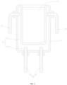
- the atomizer 100 includes a heating member 10 and at least one electrode assembly 30.
- the heating member 10 has a heating cavity 11 formed therein.
- Each electrode assembly 30 includes a first electrode 32 and a second electrode 34.
- the first electrode 32 and the second electrode 34 are both arranged to extend into the heating cavity 11.
- an electric arc can be formed between the first electrode 32 and the second electrode 34 to generate plasma by a control. That is to say, the first electrode 32 and the second electrode 34 are both arranged to extend into the heating cavity 11 of the heating member 10, and an arc is generated by a breakdown between the first electrode 32 and the second electrode 34 which are AC-powered or DC-powered.
- gas in the heating cavity 11 is ionized to form the plasma, and the plasma heats the heating cavity 11.
- an accommodating space 15 for accommodating the aerosol-forming substrate is formed in the heating member 10, and the accommodating space 15 may conduct heat with the heating cavity 11. After the inside of the heating cavity 11 is heated under the action of the plasma, the heat can be transferred to the accommodating space 15, and then the aerosol-forming substrate disposed in the accommodating space 15 is heated.
- the preheating waiting time is shortened by taking the advantages of the high energy density characteristics of the plasma heating, which is convenient for the user to use the atomizer and prevents the burnt residue of the aerosol-forming substrate caused by the too long preheating time, thereby enhancing the taste of the atomized aerosol.
- metal members such as electrodes needs not to be in direct contact with the aerosol-forming substrate during the heating process, which can prevent the aerosol-forming substrate from being mixed with metal substances after atomization, and further improve the taste of the atomized aerosol.
- the first electrode 32 and the second electrode 34 of each electrode assembly 30 are made of any one of tungsten alloy, carbon fiber, and copper alloy. Diameters of the first electrode 32 and the second electrode 34 are in a range from 0.4 to 1.0mm, and a distance between the first electrode 32 and the second electrode 34 is in a range from 5mm to 10mm.
- the number of the electrode assembly 30 is one.
- the number of the electrode assembly 30 is multiple, and the multiple electrode assemblies 30 may be discharged in parallel at the same time, or the multiple electrode assemblies 30 are discharged in sequence.
- all of the first electrodes 32 and all of the second electrodes 34 are symmetrically distributed relative to a symmetrical reference, so as to form a uniform temperature field in the heating cavity 11.
- the heating cavity 11 is filled with inert gas.
- An electric arc is generated between the first electrode 32 and the second electrode 34 in the heating cavity 11 after a breakdown therebetween, and the inert gas filled in the heating cavity 11 may be ionized to form the plasma and generate heat, and the generated heat may be efficiently transferred to the accommodating space 15 through the inert gas, thereby improving the heat transfer efficiency.
- the heating cavity 11 is filled with gases such as helium, neon, or argon. It is understandable that in other embodiments, the heating cavity 11 may also be filled with air, which is not limited here.
- a gas pressure inside the heating cavity 11 is less than the standard atmospheric pressure, so that the pressure inside the heating cavity 11 is kept at a low level and does not exert an excessive pressure on the cavity wall of the heating cavity 11 (i.e., on the heating member 10), thus allowing the wall thickness and strength of the heating member 10 to be reduced, and further improving the heat transfer efficiency.
- the gas pressure inside the heating cavity 11 is from one fifth of one standard atmospheric pressure to one standard atmospheric pressure.
- the gas pressure inside the heating cavity 11 is from one fifth of one standard atmospheric pressure to one third of one standard atmospheric pressure. It is understandable that in other embodiments, the gas pressure inside the heating cavity 11 may also be one standard atmospheric pressure, and is not limited herein.
- the heating member 10 is made of any one of quartz glass, silicon carbide, silicon nitride, zirconium oxide, and alumina oxide, such that the heating member 10 has a better insulation property, thus avoiding electric leakages when the gas inside the heating member 10 is ionized, and that the heating member 10 has a better thermal conductivity, thus making it easy for the heat generated by the ionized gas in the heating cavity 11 to be transferred to the accommodating space 15 through the heating member 10.
- the wall thickness of the heating member 10 is in a range from 0.4mm to 1.0mm, such that the strength requirements may be met and the heat may be conducted high efficiently.
- part of the outer surface of the heating member 10 is recessed inward to form a first accommodating cavity with an opening at one end, and the heating cavity 11 is arranged around an outer periphery of the first accommodating cavity.
- the first accommodating cavity is constructed as the accommodating space 15. That is, part of the outer surface of the heating member 10 is recessed inward to form the first accommodating cavity, furthermore, the heating cavity 11 is arranged around the first accommodating cavity, such that the heat generated inside the heating cavity 11 may be transferred to any positions at the outer periphery of the first accommodating cavity, thereby heating the aerosol-forming substrate in the first accommodating cavity evenly and quickly.
- the heating cavity 11 includes a first sub-cavity 112 and a second sub-cavity 114.
- the first sub-cavity 112 is annularly arranged around the outer periphery of the first accommodating cavity, and the second sub-cavity 114 is located at the bottom of the first accommodating cavity away from the opening thereof, and is in communication with the first sub-cavity 112.
- the first sub-cavity 112 surrounds the outer peripheral side of the first accommodating cavity
- the second sub-cavity 114 is located at the bottom of the first accommodating cavity
- the first sub-cavity 112 and the second sub-cavity 114 communicate to form the heating cavity 11 completely surrounding the outer periphery of the first accommodating cavity, such that heat in the first heating cavity 11 is evenly transferred in all directions.
- the electrode assembly 30 is arranged to extend into at least one of the first sub-cavity 112 and the second sub-cavity 114, that is, the electrode assembly 30 may be arranged to extend into the first sub-cavity 112, or the electrode assembly 30 may be arranged to extend into the second sub-cavity; or multiple electrode assemblies 30 may be arranged, and the electrode assemblies 30 are arranged to extend into the first sub-cavity 112 and the second sub-cavity respectively, such that the electrode assembly 30 generates an electric arc to ionize the gas in the heating cavity 11, forming the plasma and generating heat.
- the electrode assembly 30 is arranged to extend into only the first sub-cavity 112, the heat generated when the gas is ionized in the electrode assembly 30 may be transferred to the second sub-cavity 114, and the aerosol-forming substrate in the accommodating space 15 is heated through the first sub-cavity 112 and the second sub-cavity 114.
- the electrode assembly 30 is arranged to extend into only the second sub-cavity 114, the heat generated in the second sub-cavity 114 may be transferred to the first sub-cavity 112, and the aerosol-forming substrate in the accommodating space 15 is heated through the first sub-cavity 112 and the second sub-cavity 114.
- the heating cavity 11 only includes any one of the first sub-cavity 112 and the second sub-cavity 114, which is not limited herein, and the heating cavity 11 may also transfer the heat therein to the adjacent accommodating space 15.
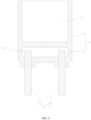
- the heating member 10 includes a mounting seat 12, and a heating seat 14 disposed on the mounting seat 12.
- the heating cavity 11 includes a third sub-cavity 116 and a fourth sub-cavity 118.
- the third sub-cavity 116 is formed inside the mounting seat 12, and the fourth sub-cavity 118 is formed inside the heating seat 14 and communicates with the third sub-cavity 116.
- the electrode assembly 30 is arranged to extend into the third sub-cavity 116.
- Mutually facing outer surfaces of the mounting seat 12 and the heating seat 14 are constructed to form the accommodating space 15 surrounding the heating seat 14.
- the heating seat 14 is in a strip shape
- the fourth sub-cavity 118 is formed inside the heating seat 14 and configured to extend along the axial direction of the heating seat 14, and communicates with the third sub-cavity 116.
- the heating seat 14 is constructed as a heating needle, and the accommodating space 15 for accommodating the aerosol-forming substrate is defined and formed between the heating seat 14 and the mounting seat 12.
- the aerosol-forming substrate is inserted on the heating seat 14, and the aerosol-forming substrate is disposed and fixed in the space (i.e., the accommodating space 15) between the mutually facing outer surfaces of the heating seat 14 and the mounting seat 12.
- the third sub-cavity 116 is formed inside the mounting seat 12
- the fourth sub-cavity 118 is formed inside the heating seat 14 and communicates with the third sub-cavity 116, and the electrode assembly 30 is arranged to extend into the third sub-cavity 116.
- the gas in the third sub-cavity 116 is ionized by the electric arc formed by a breakdown between the first electrode 32 and the second electrode 34, the plasma and the heat are formed in the third sub-cavity 116, and the formed heat can also be transferred from the third sub-cavity 116 to the fourth sub-cavity 118, making the heating seat 14 transfer heat to heat the aerosol-forming substrate.
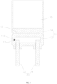
- the heating member 10 includes a mounting seat 12 and a heating seat 14 arranged on the mounting seat 12.
- the heating cavity 11 is formed inside the mounting seat 12.
- a second accommodation cavity with an opening at one end is formed inside the heating seat 14.
- the heating cavity 11 is located at the bottom of the second accommodation cavity away from the opening thereof.
- the second accommodation cavity is constructed as the accommodating space 15. That is, the heating cavity 11 is formed inside the mounting seat 12 of the heating member 10. Heat is generated inside the heating cavity 11 through the action of the first electrode 32 and the second electrode 34, and the generated heat may be transferred to the second accommodating cavity of the heating seat 14 disposed at the top, namely, transferred to the accommodating space 15, thus heating the aerosol-forming substrate in the accommodating space 15.
- the heating seat 14 and the mounting seat 12 are integrally formed to simplify the device.
- the heating seat 14 and the mounting seat 12 are formed separately.
- the heating seat 14 and the mounting seat 12 may be manufactured separately in a standardized manner, making it easy to make the atomizer 100 a standard product and improving the universality of the atomizer 100 multipurpose.
- an electronic atomization device 200 is provided.
- the electronic atomization device 200 includes the atomizer 100 above, requires a relatively short preheating waiting time, and brings a better taste of atomized aerosol.
- the heating member 10 includes the mounting seat 12 and the heating seat 14 disposed on the mounting seat 12, the heating cavity 11 includes the third sub-cavity 116 and the fourth sub-cavity 118, the third sub-cavity 116 is formed inside the mounting seat 12, and the fourth sub-cavity 118 is formed inside the heating seat 14 and in communication with the third sub-cavity 116.
- the electrode assembly 30 is arranged to extend into the third sub-cavity 116, and the mutually facing outer surfaces of the mounting seat 12 and the heating seat 14 are constructed to form the accommodating space 15 surrounding the heating seat 14. That is, the mounting seat 12 of the heating member 10 forms the third sub-cavity 116.
- Heat is generated in the third sub-cavity 116 through the action of the first electrode 32 and the second electrode 34, and the generated heat can be transferred to the fourth sub-cavity 118 of the heating seat 14 to heat the aerosol-forming substrate inserted on the heating seat 15.
- the gas inlet channel 211 is configured to go through the outer periphery of the mounting seat 12 to the accommodating space 15, such that the gas inlet channel 211 first goes through the outer periphery forming the third sub-cavity 116, and that the air flow enters the accommodating space 15 of the heating seat 14 after exchanging heat with the outer surface of the mounting seat 12.
- the gas inlet channel 211 may not go through the mounting seat 12, but directly enter the accommodating space 15 from the outside, thus simplifying the structure of the gas inlet channel.
- the arrangement of the gas inlet channel 211 is not limited herein.
Landscapes
- Nozzles (AREA)
Applications Claiming Priority (2)
| Application Number | Priority Date | Filing Date | Title |
|---|---|---|---|
| CN202123304720 | 2021-12-24 | ||
| PCT/CN2022/129433 WO2023116221A1 (zh) | 2021-12-24 | 2022-11-03 | 雾化器及电子雾化装置 |
Publications (2)
| Publication Number | Publication Date |
|---|---|
| EP4427618A1 true EP4427618A1 (de) | 2024-09-11 |
| EP4427618A4 EP4427618A4 (de) | 2025-05-21 |
Family
ID=86901234
Family Applications (1)
| Application Number | Title | Priority Date | Filing Date |
|---|---|---|---|
| EP22909538.5A Pending EP4427618A4 (de) | 2021-12-24 | 2022-11-03 | Zerstäuber und elektronische zerstäubungsvorrichtung |
Country Status (4)
| Country | Link |
|---|---|
| EP (1) | EP4427618A4 (de) |
| JP (1) | JP7737558B2 (de) |
| CN (1) | CN222367076U (de) |
| WO (1) | WO2023116221A1 (de) |
Families Citing this family (2)
| Publication number | Priority date | Publication date | Assignee | Title |
|---|---|---|---|---|
| CN120345739A (zh) * | 2024-01-22 | 2025-07-22 | 沃德韦国际控股有限公司 | 加热模组和气溶胶生成装置 |
| CN222149068U (zh) * | 2024-01-22 | 2024-12-13 | 沃德韦国际控股有限公司 | 加热模组和气溶胶生成装置 |
Family Cites Families (7)
| Publication number | Priority date | Publication date | Assignee | Title |
|---|---|---|---|---|
| GB2480122A (en) | 2010-03-01 | 2011-11-09 | Oglesby & Butler Res & Dev Ltd | A vaporising device with removable heat transfer element |
| CN203952435U (zh) | 2014-05-27 | 2014-11-26 | 李述彦 | 电子烟雾化器和电子烟 |
| CN204579893U (zh) | 2015-04-02 | 2015-08-26 | 赵惠萍 | 电子烟雾化器 |
| CN108308725B (zh) * | 2018-05-04 | 2024-06-11 | 声海电子(深圳)有限公司 | 一种电子烟 |
| JP7385860B2 (ja) | 2019-08-28 | 2023-11-24 | 株式会社 徳武製作所 | 吸引・吸入器 |
| US20220361574A1 (en) * | 2019-09-06 | 2022-11-17 | Jt International Sa | Aerosol Generation Device and Heating Chamber Therefor |
| CN212987299U (zh) * | 2020-08-18 | 2021-04-16 | 深圳拓邦股份有限公司 | 一种直流等离子加热装置及炒菜机 |
-
2022
- 2022-11-03 JP JP2024529190A patent/JP7737558B2/ja active Active
- 2022-11-03 EP EP22909538.5A patent/EP4427618A4/de active Pending
- 2022-11-03 WO PCT/CN2022/129433 patent/WO2023116221A1/zh not_active Ceased
- 2022-11-03 CN CN202290000764.9U patent/CN222367076U/zh active Active
Also Published As
| Publication number | Publication date |
|---|---|
| JP7737558B2 (ja) | 2025-09-10 |
| EP4427618A4 (de) | 2025-05-21 |
| WO2023116221A1 (zh) | 2023-06-29 |
| CN222367076U (zh) | 2025-01-21 |
| JP2024541391A (ja) | 2024-11-08 |
Similar Documents
| Publication | Publication Date | Title |
|---|---|---|
| CN217117529U (zh) | 雾化器及电子雾化装置 | |
| EP4427618A1 (de) | Zerstäuber und elektronische zerstäubungsvorrichtung | |
| CN217509910U (zh) | 发热件及电子雾化装置 | |
| WO2023165209A1 (zh) | 微波加热组件及气溶胶产生装置和气溶胶生成系统 | |
| CN219373809U (zh) | 电子雾化装置 | |
| CN115067565A (zh) | 气溶胶产生装置及其加热组件 | |
| WO2023024812A1 (zh) | 加热器件及电子雾化装置 | |
| WO2024055731A1 (zh) | 加热组件及气溶胶生成装置 | |
| US20250280885A1 (en) | Electrode and electronic atomization device | |
| CN217089631U (zh) | 加热元件及电子雾化装置 | |
| WO2024027386A1 (zh) | 加热组件、雾化器及气溶胶生成装置 | |
| WO2024234956A1 (zh) | 一种发热组件、雾化器及气溶胶生成装置 | |
| EP4464181A1 (de) | Zerstäuber und elektronische zerstäubungsvorrichtung | |
| EP4427607B1 (de) | Zerstäubungsvorrichtung und elektronische zigarette | |
| WO2024114147A1 (zh) | 发热元件、电子雾化装置和雾化方法 | |
| CN219373819U (zh) | 气溶胶产生装置及气溶胶产生系统 | |
| CN118216718A (zh) | 雾化装置 | |
| CN115736353A (zh) | 一种雾化芯、雾化器及气溶胶生成装置 | |
| CN218245687U (zh) | 发热组件以及电子雾化装置 | |
| CN223554323U (zh) | 发热组件、雾化装置及雾化设备 | |
| CN220571568U (zh) | 空气加热器及加热不燃烧气溶胶生成装置 | |
| CN217906342U (zh) | 雾化器及电子雾化装置 | |
| CN223667274U (zh) | 雾化装置及雾化设备 | |
| CN223943775U (zh) | 加热组件及气溶胶生成装置 | |
| CN218379894U (zh) | 一种带有螺旋流道的液体速热装置的净水器 |
Legal Events
| Date | Code | Title | Description |
|---|---|---|---|
| STAA | Information on the status of an ep patent application or granted ep patent |
Free format text: STATUS: THE INTERNATIONAL PUBLICATION HAS BEEN MADE |
|
| PUAI | Public reference made under article 153(3) epc to a published international application that has entered the european phase |
Free format text: ORIGINAL CODE: 0009012 |
|
| STAA | Information on the status of an ep patent application or granted ep patent |
Free format text: STATUS: REQUEST FOR EXAMINATION WAS MADE |
|
| 17P | Request for examination filed |
Effective date: 20240603 |
|
| AK | Designated contracting states |
Kind code of ref document: A1 Designated state(s): AL AT BE BG CH CY CZ DE DK EE ES FI FR GB GR HR HU IE IS IT LI LT LU LV MC ME MK MT NL NO PL PT RO RS SE SI SK SM TR |
|
| RAP3 | Party data changed (applicant data changed or rights of an application transferred) |
Owner name: SHENZHEN SMOORE TECHNOLOGY LIMITED |
|
| DAV | Request for validation of the european patent (deleted) | ||
| DAX | Request for extension of the european patent (deleted) | ||
| REG | Reference to a national code |
Ref country code: DE Ref legal event code: R079 Free format text: PREVIOUS MAIN CLASS: A24F0047000000 Ipc: A24F0040460000 |
|
| A4 | Supplementary search report drawn up and despatched |
Effective date: 20250422 |
|
| RAP3 | Party data changed (applicant data changed or rights of an application transferred) |
Owner name: SHENZHEN SMOORE TECHNOLOGY LIMITED |
|
| RIC1 | Information provided on ipc code assigned before grant |
Ipc: A24F 40/20 20200101ALN20250415BHEP Ipc: A24F 40/46 20200101AFI20250415BHEP |