EP4425146B1 - Ultragrosse physikalische simulationsanlage für tiefbaukatastrophen - Google Patents
Ultragrosse physikalische simulationsanlage für tiefbaukatastrophen Download PDFInfo
- Publication number
- EP4425146B1 EP4425146B1 EP23711930.0A EP23711930A EP4425146B1 EP 4425146 B1 EP4425146 B1 EP 4425146B1 EP 23711930 A EP23711930 A EP 23711930A EP 4425146 B1 EP4425146 B1 EP 4425146B1
- Authority
- EP
- European Patent Office
- Prior art keywords
- ultra
- hydraulic actuator
- actuator group
- deep
- physical simulation
- Prior art date
- Legal status (The legal status is an assumption and is not a legal conclusion. Google has not performed a legal analysis and makes no representation as to the accuracy of the status listed.)
- Active
Links
Images


Classifications
-
- G—PHYSICS
- G01—MEASURING; TESTING
- G01M—TESTING STATIC OR DYNAMIC BALANCE OF MACHINES OR STRUCTURES; TESTING OF STRUCTURES OR APPARATUS, NOT OTHERWISE PROVIDED FOR
- G01M99/00—Subject matter not provided for in other groups of this subclass
- G01M99/005—Testing of complete machines, e.g. washing-machines or mobile phones
-
- G—PHYSICS
- G06—COMPUTING OR CALCULATING; COUNTING
- G06F—ELECTRIC DIGITAL DATA PROCESSING
- G06F30/00—Computer-aided design [CAD]
- G06F30/20—Design optimisation, verification or simulation
-
- G—PHYSICS
- G01—MEASURING; TESTING
- G01N—INVESTIGATING OR ANALYSING MATERIALS BY DETERMINING THEIR CHEMICAL OR PHYSICAL PROPERTIES
- G01N3/00—Investigating strength properties of solid materials by application of mechanical stress
- G01N3/02—Details
- G01N3/06—Special adaptations of indicating or recording means
-
- G—PHYSICS
- G01—MEASURING; TESTING
- G01N—INVESTIGATING OR ANALYSING MATERIALS BY DETERMINING THEIR CHEMICAL OR PHYSICAL PROPERTIES
- G01N3/00—Investigating strength properties of solid materials by application of mechanical stress
- G01N3/32—Investigating strength properties of solid materials by application of mechanical stress by applying repeated or pulsating forces
- G01N3/36—Investigating strength properties of solid materials by application of mechanical stress by applying repeated or pulsating forces generated by pneumatic or hydraulic means
-
- E—FIXED CONSTRUCTIONS
- E21—EARTH OR ROCK DRILLING; MINING
- E21F—SAFETY DEVICES, TRANSPORT, FILLING-UP, RESCUE, VENTILATION, OR DRAINING IN OR OF MINES OR TUNNELS
- E21F17/00—Methods or devices for use in mines or tunnels, not covered elsewhere
-
- G—PHYSICS
- G01—MEASURING; TESTING
- G01N—INVESTIGATING OR ANALYSING MATERIALS BY DETERMINING THEIR CHEMICAL OR PHYSICAL PROPERTIES
- G01N2203/00—Investigating strength properties of solid materials by application of mechanical stress
- G01N2203/0001—Type of application of the stress
- G01N2203/0003—Steady
-
- G—PHYSICS
- G01—MEASURING; TESTING
- G01N—INVESTIGATING OR ANALYSING MATERIALS BY DETERMINING THEIR CHEMICAL OR PHYSICAL PROPERTIES
- G01N2203/00—Investigating strength properties of solid materials by application of mechanical stress
- G01N2203/0001—Type of application of the stress
- G01N2203/001—Impulsive
-
- G—PHYSICS
- G01—MEASURING; TESTING
- G01N—INVESTIGATING OR ANALYSING MATERIALS BY DETERMINING THEIR CHEMICAL OR PHYSICAL PROPERTIES
- G01N2203/00—Investigating strength properties of solid materials by application of mechanical stress
- G01N2203/0014—Type of force applied
- G01N2203/0016—Tensile or compressive
- G01N2203/0019—Compressive
-
- G—PHYSICS
- G01—MEASURING; TESTING
- G01N—INVESTIGATING OR ANALYSING MATERIALS BY DETERMINING THEIR CHEMICAL OR PHYSICAL PROPERTIES
- G01N2203/00—Investigating strength properties of solid materials by application of mechanical stress
- G01N2203/003—Generation of the force
- G01N2203/0042—Pneumatic or hydraulic means
- G01N2203/0048—Hydraulic means
-
- G—PHYSICS
- G01—MEASURING; TESTING
- G01N—INVESTIGATING OR ANALYSING MATERIALS BY DETERMINING THEIR CHEMICAL OR PHYSICAL PROPERTIES
- G01N2203/00—Investigating strength properties of solid materials by application of mechanical stress
- G01N2203/0058—Kind of property studied
- G01N2203/006—Crack, flaws, fracture or rupture
- G01N2203/0067—Fracture or rupture
-
- G—PHYSICS
- G01—MEASURING; TESTING
- G01N—INVESTIGATING OR ANALYSING MATERIALS BY DETERMINING THEIR CHEMICAL OR PHYSICAL PROPERTIES
- G01N2203/00—Investigating strength properties of solid materials by application of mechanical stress
- G01N2203/02—Details not specific for a particular testing method
- G01N2203/022—Environment of the test
- G01N2203/0222—Temperature
- G01N2203/0226—High temperature; Heating means
-
- G—PHYSICS
- G01—MEASURING; TESTING
- G01N—INVESTIGATING OR ANALYSING MATERIALS BY DETERMINING THEIR CHEMICAL OR PHYSICAL PROPERTIES
- G01N2203/00—Investigating strength properties of solid materials by application of mechanical stress
- G01N2203/02—Details not specific for a particular testing method
- G01N2203/025—Geometry of the test
- G01N2203/0256—Triaxial, i.e. the forces being applied along three normal axes of the specimen
-
- G—PHYSICS
- G01—MEASURING; TESTING
- G01N—INVESTIGATING OR ANALYSING MATERIALS BY DETERMINING THEIR CHEMICAL OR PHYSICAL PROPERTIES
- G01N2203/00—Investigating strength properties of solid materials by application of mechanical stress
- G01N2203/02—Details not specific for a particular testing method
- G01N2203/06—Indicating or recording means; Sensing means
- G01N2203/0641—Indicating or recording means; Sensing means using optical, X-ray, ultraviolet, infrared or similar detectors
-
- G—PHYSICS
- G01—MEASURING; TESTING
- G01N—INVESTIGATING OR ANALYSING MATERIALS BY DETERMINING THEIR CHEMICAL OR PHYSICAL PROPERTIES
- G01N2203/00—Investigating strength properties of solid materials by application of mechanical stress
- G01N2203/02—Details not specific for a particular testing method
- G01N2203/06—Indicating or recording means; Sensing means
- G01N2203/0658—Indicating or recording means; Sensing means using acoustic or ultrasonic detectors
-
- G—PHYSICS
- G01—MEASURING; TESTING
- G01N—INVESTIGATING OR ANALYSING MATERIALS BY DETERMINING THEIR CHEMICAL OR PHYSICAL PROPERTIES
- G01N2203/00—Investigating strength properties of solid materials by application of mechanical stress
- G01N2203/02—Details not specific for a particular testing method
- G01N2203/06—Indicating or recording means; Sensing means
- G01N2203/067—Parameter measured for estimating the property
- G01N2203/0676—Force, weight, load, energy, speed or acceleration
-
- G—PHYSICS
- G01—MEASURING; TESTING
- G01N—INVESTIGATING OR ANALYSING MATERIALS BY DETERMINING THEIR CHEMICAL OR PHYSICAL PROPERTIES
- G01N2203/00—Investigating strength properties of solid materials by application of mechanical stress
- G01N2203/02—Details not specific for a particular testing method
- G01N2203/06—Indicating or recording means; Sensing means
- G01N2203/067—Parameter measured for estimating the property
- G01N2203/0682—Spatial dimension, e.g. length, area, angle
-
- G—PHYSICS
- G01—MEASURING; TESTING
- G01N—INVESTIGATING OR ANALYSING MATERIALS BY DETERMINING THEIR CHEMICAL OR PHYSICAL PROPERTIES
- G01N3/00—Investigating strength properties of solid materials by application of mechanical stress
- G01N3/02—Details
- G01N3/06—Special adaptations of indicating or recording means
- G01N3/068—Special adaptations of indicating or recording means with optical indicating or recording means
-
- G—PHYSICS
- G01—MEASURING; TESTING
- G01N—INVESTIGATING OR ANALYSING MATERIALS BY DETERMINING THEIR CHEMICAL OR PHYSICAL PROPERTIES
- G01N3/00—Investigating strength properties of solid materials by application of mechanical stress
- G01N3/08—Investigating strength properties of solid materials by application of mechanical stress by applying steady tensile or compressive forces
- G01N3/10—Investigating strength properties of solid materials by application of mechanical stress by applying steady tensile or compressive forces generated by pneumatic or hydraulic pressure
- G01N3/12—Pressure testing
Definitions
- the invention relates to the technical field of rock mechanics tests, and particularly relates to an ultra-large physical simulation facility for deep engineering disasters, which is used for indoor simulation of the whole inoculation process of multiple types of deep engineering disasters induced by deep rock engineering excavation, mining, and the like.
- Deep-ground engineering represented by deep resource mining, deep buried traffic tunnel (hole) excavation, deep energy development, and the like. is developing from the kilometer burial depth to the ten-thousand-meter burial depth. Its occurrence environment is characterized by ultra-high tectonic stress, ultra-high fluid pressure, ultra-high temperature, and other extreme features.
- the geological structure shows the complexities of large-scale folds, faults, hard structural planes, layered structures, trap structures, and the like.
- three-dimensional physical model tests on similar materials prepare a physical model sample similar to engineering rock masses, boundary stress is applied to the physical model sample through a three-dimensional loading system, stress, deformation, fracture and other multi-element information of the physical model sample are monitored during the excavation process, and simulation and monitoring of the incubation process of the deep engineering disasters are realized.
- This type of test can truly restore the geological structure relatively, control the three-dimensional boundary stress, simulate engineering excavation behaviors, selectively control induction conditions, and physically reproduce the fracture and disaster causing process of important parts.
- the test is a basic means to deal with the mechanism analysis and early warning research of major geological disasters.
- Chinese patent application No. 201310336255.0 discloses a true-triaxial rockburst physical simulation test system for deep tunnels, which is mainly used to study the induction mechanism of rockbursts by blasting vibration
- Chinese patent application No. 201610326802.0 discloses a multifunctional physical simulation test system for coal and rock engineering and a coal and rock model test method, which are mainly used to simulate coal and gas outburst problems under the action of ground stress and gas stress
- 201780002869.1 discloses an intelligent CNC ultra-high pressure true three-dimensional non-uniform loading and unloading and pressure stabilization model test system, and the system has a loading capacity of 4500t and is mainly used to simulate the discontinuous deformation and failure process of deep cavern excavation; and Chinese patent application No. 202111164829.1 discloses a multifunctional three-dimensional similar simulation test platform and test method, which mainly simulate microwave thermal rock breaking and crack enhancement. Further, Chinese patent application CN 115 372 152 discloses a large-scale three-dimensional physical simulation test system for the whole process of rockburst breeding in deep engineering and Chinese patent application CN 114 965 006 discloses and engineering rock mass dynamics simulation test system.
- the existing three-dimensional physical model test on similar materials still has the following problems: 1) the simulated geological conditions, occurrence environment and engineering activities are single, and the deep-ground engineering activities such as oil, gas and water multiphase multi-component complex cavern group excavation, horizontal well fracturing, deep geothermal exploitation, deep metal mine stope group mining, ventilation, filling, and the like cannot be simulated; 2) the model size is mainly in 1-2m, and the physical model similarity ratio is too large, thereby resulting in distortion of geological structure information, the complexity of deep engineering cannot be effectively reproduced, and the ability of engineering behavior simulation and online monitoring is limited; 3) physical simulation of the engineering scope with the depth of 100-1000-meter scale cannot be realized; 4) the tectonic stress environment in deep engineering cannot be simulated, so that study on a geological hazard mechanism under the coupling of tectonic stress and engineering activities is limited; and 5) the loading capacity is less than 10000t, so that high ground stress boundary conditions cannot be applied to an ultra-large similar material model
- the problems that need to be solved include: mechanical design analysis and limit processing technology guarantee of an ultra-large geological model loading frame under extreme conditions, uncoordinated deformation of the structure caused by local stress concentration of the frame structure under the ultra-high load conditions, and low loading synchronicity and stability control accuracy of same axial stress for ultra-large sections.
- the ultra-large physical simulation facility for deep engineering disasters also needs to solve the following problems: 1) the coupled simulation problem of extreme occurrence environment such as deep ultra-high tectonic stress, ultra-high fluid pressure and ultra-high temperature; 2) the simulation problem of deep-ground complex geological structures of large-scale folds, faults, hard structural planes, layered structures, trap structures, and the like.; 3) the problems of simulation and transparent monitoring of the incubation process of multiple types of disasters induced by deep and complex engineering activities; 4) the simulation problems of complex stress environments such as deep-ground high ground stress, tectonic stress, asymmetric stress and excavation disturbance stress; and 5) the problems of high stress loading, uniformly-distributed stress loading and long-term stable loading of the ultra-large physical model sample.
- the invention provides an ultra-large physical simulation facility for deep engineering disasters.
- refined 3D printing of a multiphase multi-component complex geological structure can be realized, and besides, the loading requirements of a multiphase multi-component 3D printing geological body model under deep complex geological conditions for true-triaxial high stress, tectonic stress and disturbance stress can be met, multi-element information of the whole inoculation process of deformation, ultrasound, acoustic emission and geological disasters under complex engineering activities such as excavation, mining, extraction and ventilation can be intelligently and transparently monitored; and multi-task intelligent collaborative main control and big data cloud sharing can be realized, and simulation of 100-10000 m deep rock stress environment in the range of 1:40-1:100 stress similarity ratio and 50000-12550000 m 3 engineering scope similarity ratio can be met.
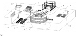
- an ultra-large physical simulation facility for deep engineering disasters comprises a long-time large-load loading system for a geological model, a 3D printing system of a deep oil, gas and water multiphase multi-component complex geological body model, a high-temperature-chemical-multiphase fluid collaborative injection, monitoring and control system, a robot excavation and monitoring system for a complex engineering structure in a model under deep geological environment, an intelligent ventilation system for a deep metal mine complex drilling, mining and transferring network, an intelligent filling system for a deep metal mine ultra-large stope, a deep-well enhanced geothermal safe intelligent mining system, an all-spatial-temporal intelligent high-precision monitoring system for an excavation and fracture process of a large-scale geological model, and an ultra-large multi-task intelligent collaborative main control and digital twin system for physical simulation tests, wherein the long-time large-load loading system for the geological model comprises a large concrete foundation pit mounting slot, an ultra-large physical simulation test device for deep
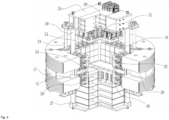
- the ultra-large physical simulation test device for deep engineering disasters comprises a horizontal ultra-large reaction frame, a vertical ultra-large reaction frame, a first array distributed hydraulic actuator group, a second array distributed hydraulic actuator group, a third array distributed hydraulic actuator group, a fourth array distributed hydraulic actuator group, a fifth array distributed hydraulic actuator group, a linear distributed hydraulic actuator group and ultra-long stroke lifting and locking hydraulic cylinders
- the vertical ultra-large reaction frame comprises a reaction top plate, support columns and a reaction base
- the horizontal ultra-large reaction frame adopts a circular structure being circular in an outer part and square in an inner part
- the horizontal ultra-large reaction frame is fixedly mounted in the large concrete foundation pit mounting slot, and an excavation channel is provided in aside of the horizontal ultra-large reaction frame
- the horizontal ultra-large reaction frame is formed by splicing eight segments of arch beams through carbon fiber winding
- the vertical ultra-large reaction frame is located inside the horizontal ultra-large reaction frame
- the reaction base is located directly below the reaction top plate, the reaction base and the reaction top plate are fixed
- All single hydraulic actuators contained in the linear distributed hydraulic actuator group are dynamic hydraulic actuators, and a maximum disturbance frequency of the dynamic hydraulic actuators is 5 Hz; an external bracket of each dynamic hydraulic actuator comprises four guide rods resisting lateral force; and each dynamic hydraulic actuator adopts a double-output rod symmetrical structure, a large-flow integrated valve block is arranged outside a cylinder barrel of each dynamic hydraulic actuator, and each large-flow integrated valve block is provided with double servo valves.
- the structures of the single hydraulic actuators contained in the first array distributed hydraulic actuator group, the second array distributed hydraulic actuator group, the third array distributed hydraulic actuator group, the fourth array distributed hydraulic actuator group and the fifth array distributed hydraulic actuator group are the same, a magneto strictive displacement sensor is arranged between a piston inside a cylinder barrel and a bottom plate of the cylinder barrel of each single hydraulic actuator, a servo valve and an energy accumulator are arranged outside the cylinder barrel of each single hydraulic actuator, and a load sensor is arranged at a piston end of each single hydraulic actuator.
- the single hydraulic actuators at centers of the first array distributed hydraulic actuator group, the second array distributed hydraulic actuator group, the third array distributed hydraulic actuator group, the fourth array distributed hydraulic actuator group and the fifth array distributed hydraulic actuator group all adopt through-type hydraulic actuators, and a piston rod of each through-type hydraulic actuator adopts a double-output rod hollow structure.
- a hydraulic oil source system is arranged in the cluster large-flow high-pressure hydraulic pump station, adopts a distributed hydraulic station design scheme, and comprises eight hydraulic stations in total; and the first five hydraulic stations are respectively connected with the first array distributed hydraulic actuator group, the second array distributed hydraulic actuator group, the third array distributed hydraulic actuator group, the fourth array distributed hydraulic actuator group and the fifth array distributed hydraulic actuator group, the sixth hydraulic station is connected with the linear distributed hydraulic actuator group, the seventh hydraulic station is connected with the ultra-long stroke lifting and locking hydraulic cylinders, and the eighth hydraulic station serves as a standby hydraulic station.
- the long-time large-load loading system for the geological model adopts a distributed network control system with a single actuator controller as a node for redundancy control of the system and hot replacement of the controller;
- the distributed network control system comprises three layers of structures, wherein a main controller is in a first layer, loading surface array controllers are in a second layer, and a controller of each independent loading actuator is in a third layer;
- the main controller is used for human-computer interaction, test management, test mode setting, and local storage and upload of test data;
- the main controller performs data exchange with the ultra-large multi-task intelligent collaborative main control and digital twin system for the physical simulation tests through a Modbus TCP/UDP protocol;
- the main controller performs data exchange with the loading surface array controller distributed on each loading surface through a network cable according to the Modbus TCP/UDP protocol;
- the loading surface array controllers perform data exchange with the controller of each independent loading actuator through a network cable according to the Modbus TCP/UDP protocol.
- the invention can simulate complex engineering activities.
- the invention can realize the true-triaxial boundary stress uniform loading and tectonic stress simulation of an ultra-large physical model sample.
- the invention can realize three-dimensional visualization of the whole inoculation process of geological hazards of the physical model sample.
- the precise reconstruction of a complex geological structure and a geological model of extreme occurrence environment can be realized through an ultra-large physical simulation digital twin technology of deep engineering disasters.
- real-time display of complex engineering activities such as excavation, mining, extraction, ventilation and filling can be realized, and supplemented with an all-spatial-temporal intelligent high-precision monitoring technology of an excavation and fracture process of a large-scale geological model, real-time monitoring of crack location, direction and scale can be realized, and real-time rendering of the whole inoculation process of geological disasters can be realized.
- 1 long-time large-load loading system for geological model
- 2 3D printing system of deep oil, gas and water multiphase multi-component complex geological body model
- 3 high-temperature-chemical-multiphase fluid collaborative injection, monitoring and control system
- 4 robot excavation and monitoring system for complex engineering structure in model under deep geological environment
- 5 intelligent ventilation system for deep metal mine complex drilling, mining and transferring network
- 6 intelligent filling system for deep metal mine ultra-large stope
- 7 deep-well enhanced geothermal safe intelligent mining system
- 8 all-spatial-temporal intelligent high-precision monitoring system for excavation and fracture process of large-scale geological model
- 9 ultra-large multi-task intelligent collaborative main control and digital twin system for physical simulation tests
- 10 large concrete foundation pit mounting slot
- 11 ultra-large physical simulation test device for deep engineering disasters
- 12 distributed main control center
- 13 cluster large-flow high-pressure hydraulic pump station
- 14 circulating cooling water cooling tower
- 15 electric control cabinet
- 16 model sample transferring device
- 17 horizontal ultra-large reaction
- the ultra-large physical simulation facility for deep engineering disasters comprises a long-time large-load loading system 1 for a geological model, a 3D printing system 2 of a deep oil, gas and water multiphase multi-component complex geological body model, a high-temperature-chemical-multiphase fluid collaborative injection, monitoring and control system 3, a robot excavation and monitoring system 4 for a complex engineering structure in a model under deep geological environment, an intelligent ventilation system 5 for a deep metal mine complex drilling, mining and transferring network, an intelligent filling system 6 for a deep metal mine ultra-large stope, a deep-well enhanced geothermal safe intelligent mining system 7, an all-spatial-temporal intelligent high-precision monitoring system 8 for an excavation and fracture process of a large-scale geological model, and an ultra-large multi-task intelligent collaborative main control and digital twin system 9 for physical simulation tests, wherein the long-time large-load loading system 1 for a geological model comprises a large concrete foundation pit mounting slot 10, an ultra-large physical simulation test device
- the ultra-large physical simulation test device 11 for deep engineering disasters comprises a horizontal ultra-large reaction frame 17, a vertical ultra-large reaction frame, a first array distributed hydraulic actuator group 18, a second array distributed hydraulic actuator group 19, a third array distributed hydraulic actuator group 20, a fourth array distributed hydraulic actuator group 21, a fifth array distributed hydraulic actuator group 22, a linear distributed hydraulic actuator group 23 and ultra-long stroke lifting and locking hydraulic cylinders 24;
- the vertical ultra-large reaction frame comprises a reaction top plate 25, support columns 26 and a reaction base 27;
- the horizontal ultra-large reaction frame 17 adopts a circular structure being circular in an outer part and square in an inner part;
- the horizontal ultra-large reaction frame 17 is fixedly mounted in the large concrete foundation pit mounting slot 10, and an excavation channel 28 is provided in aside of the horizontal ultra-large reaction frame 17; in the embodiment, a diameter of an outer circle of the horizontal ultra-large reaction frame 17 is 20 m, an inner square side length is 10 m, a vertical height is 5.5 m, and a channel diameter of the excavation channel 28 is
- the horizontal ultra-large reaction frame 17 is formed by splicing eight segments of arch beams through carbon fiber winding; the vertical ultra-large reaction frame is located inside the horizontal ultra-large reaction frame 17; the reaction base 27 is located directly below the reaction top plate 25, and the reaction base 27 and the reaction top plate 25 are fixedly connected by the four uniformly-distributed support columns 26, and the vertical ultra-large reaction frame forms a double-beam four-column preload frame structure; a drilling channel 29 is formed in the reaction top plate 25; in the embodiment, a space between the reaction base 27 and the reaction top plate 25 is 8.5 m, the number of drilling channels 29 is two, a channel diameter of the drilling channels 29 is 200 mm, the support columns 26 adopt a hollow structure, each support column 26 is internally provided with a pre-stressed pull
- the pre-stressed pull rods inside the support columns 26 need to be in a tensile stress state, so that the support columns 26 need to always be in a yield stress state;
- four ultra-long stroke lifting and locking hydraulic cylinders 24 are uniformly arranged between the horizontal ultra-large reaction frame 17 and the reaction top plate 25; a cylinder barrel of each ultra-long stroke lifting and locking hydraulic cylinder 24 is embedded and fixed in the horizontal ultra-large reaction frame 17, and a piston rod of each ultra-long stroke lifting and locking hydraulic cylinder 24 is upwards to be fixedly connected with the reaction top plate 25;
- the first array distributed hydraulic actuator group 18 is arranged on a lower surface of the reaction top plate 25;
- the second array distributed hydraulic actuator group 19 the third array distributed hydraulic actuator group 20, the fourth array distributed hydraulic actuator group 21 and the fifth array distributed hydraulic
- All single hydraulic actuators contained in the linear distributed hydraulic actuator group 23 are dynamic hydraulic actuators, and a maximum disturbance frequency of the dynamic hydraulic actuators is 5 Hz; an external bracket of each dynamic hydraulic actuator comprises four guide rods resisting lateral force; the dynamic hydraulic actuators adopt a double-output rod symmetrical structure, a large-flow integrated valve block is arranged outside a cylinder barrel of each dynamic hydraulic actuator, and each large-flow integrated valve block is provided with double servo valves.
- the structures of the single hydraulic actuators contained in the first array distributed hydraulic actuator group 18, the second array distributed hydraulic actuator group 19, the third array distributed hydraulic actuator group 20, the fourth array distributed hydraulic actuator group 21 and the fifth array distributed hydraulic actuator group 22 are the same, a magneto strictive displacement sensor is arranged between a piston inside a cylinder barrel and a bottom plate of the cylinder barrel of each single hydraulic actuator, a servo valve and an energy accumulator are arranged outside the cylinder barrel of each single hydraulic actuator, and a load sensor is arranged at a piston end of each single hydraulic actuator.
- the single hydraulic actuators 31 at centers of the first array distributed hydraulic actuator group 18, the second array distributed hydraulic actuator group 19, the third array distributed hydraulic actuator group 20, the fourth array distributed hydraulic actuator group 21 and the fifth array distributed hydraulic actuator group 22 all adopt through-type hydraulic actuators, and a piston rod of each through-type hydraulic actuator 31 adopts a double-output rod hollow structure.
- the number of the through-type hydraulic actuators 31 at a center of the first array distributed hydraulic actuator group 18 is two and a hollow diameter of the piston rod is 300 mm.
- the number of the through-type hydraulic actuators 31 at a center of the second array distributed hydraulic actuator group 19, at a center of the third array distributed hydraulic actuator group 20, at a center of the fourth array distributed hydraulic actuator group 21 and at a center of the fifth array distributed hydraulic actuator group 22 is one respectively, and a hollow diameter of the piston rod is 500mm.
- a hydraulic oil source system is arranged in the cluster large-flow high-pressure hydraulic pump station 13, adopts a distributed hydraulic station design scheme, and comprises eight hydraulic stations 30 in total; and the first five hydraulic stations are respectively connected with the first array distributed hydraulic actuator group 18, the second array distributed hydraulic actuator group 19, the third array distributed hydraulic actuator group 20, the fourth array distributed hydraulic actuator group 21 and the fifth array distributed hydraulic actuator group 22, the sixth hydraulic station is connected with the linear distributed hydraulic actuator group 23, the seventh hydraulic station is connected with the ultra-long stroke lifting and locking hydraulic cylinders 24, and the eighth hydraulic station serves as a standby hydraulic station.
- the maximum flow of the hydraulic station is 4000L/min, and the rated working pressure of the hydraulic station is 21MPa.
- the long-time large-load loading system for a geological model 1 adopts a distributed network control system with a single actuator controller as a node for redundancy control of the system and hot replacement of the controller; in order to realize the clarity of control logic and the convenience of system maintenance, and more importantly, to ensure smooth implementation of long-term electro-hydraulic servo load holding tests, the distributed network control system comprises three layers of structures, wherein a main controller is in a first layer, loading surface array controllers are in a second layer, and the controller of each independent loading actuator is in a third layer; the main controller is used for human-computer interaction, test management, test mode setting, and local storage and upload of test data; the main controller performs data exchange with the ultra-large multi-task intelligent collaborative main control and digital twin system 9 for physical simulation tests through a Modbus TCP/UDP protocol; the main controller performs data exchange with the loading surface array controller distributed on each loading surface through a network cable according to the Modbus TCP/UDP protocol; and the loading surface array controllers perform data exchange with
- a control channel of the long-time large-load loading system 1 for a geological model in the embodiment comprises 125 static control channels and 5 dynamic control channels, so that the composition of the system is extremely complex. If a traditional centralized control system is adopted, each controller is generally limited by no more than 8 closed-loop control channels. In addition, up to 30 centralized controllers will appear in the controller system for redundant control and protection switching judgement, resulting in a very complex control logic, and a large number of interconnections, and anti-interference ability and reliability are greatly reduced. Once a certain controller fails, there will be 8 actuators out of control at the same time, which will be disastrous for the reliability of the tests.
- the control logic is simple and clear, the connection is simple and reliable, and a dual-output displacement sensor and a protection and switching controller as well as a loading surface array controller work together to realize the redundant control of the loading system and the hot replacement of the controller, so that long-time electro-hydraulic servo stable load holding of 5000 hours for the loading control system can be guaranteed.
- the simulation of fracture rockbursts is taken as an example, and the test is performed through the ultra-large physical simulation facility for deep engineering disasters, comprising the following steps:
- Step I preparing the ultra-large physical model sample.
- The3D printing system 2 for the deep multiphase multi-component complex geological body model is used to print and make the ultra-large physical model sample on the model sample transferring device 16, wherein the size of the ultra-large physical model sample is 5 m ⁇ 5 m ⁇ 5 m, including a structural plane with an inclination of 45 degrees, a length of 3.5 m and a width of 1 m; during the printing process of the ultra-large physical model sample, a stress-strain-vibration-acoustic emission-ultrasonic integrated sensor, a fiber grating high-sensitivity fine temperature-pressure-stress integrated monitoring sensor and an acoustic emission sensor are pre-embedded in the ultra-large physical model sample.
- Step II transferring the ultra-large physical model sample.
- the model sample transferring device 16 is used to transfer the ultra-large physical model sample to the ultra-large physical simulation test device 11 for deep engineering disasters, so that the ultra-large physical model sample is accurately placed on the upper surface of the reaction base 27, and then leads of the stress-strain-vibration-acoustic emission-ultrasonic integrated sensor in the ultra-large physical model sample, the fiber grating high-sensitivity fine temperature-pressure-stress integrated monitoring sensor and the acoustic emission sensor, which are pre-embedded in the ultra-large physical model sample, are electrically connected with the large-scale all-spatial-temporal intelligent high-precision monitoring system 8 for an excavation and fracture process of a geological model, and each sensor is tested before the test to ensure that all sensors can work normally.
- Step III performing cooperative main control connection.
- All the interfaces of the all-spatial-temporal intelligent high-precision monitoring system 8 for an excavation and fracture process of a large-scale geological model, the long-time large-load loading system 1 for a geological model, and the robot excavation and monitoring system 4 for a complex engineering structure in a model under deep geological environment are electrically connected with the ultra-large multi-task intelligent collaborative main control and digital twin system 9 for physical simulation tests.
- Step IV mounting the ultra-large physical model sample.
- the ultra-long stroke lifting and locking hydraulic cylinders 24 are controlled to perform retraction action, so that under the driving of the ultra-long stroke lifting and locking hydraulic cylinders 24, the vertical ultra-large reaction frame moves downward as a whole until the ultra-large physical model sample in the vertical ultra-large reaction frame accurately enters the horizontal ultra-large reaction frame 17.
- Step V pre-clamping the ultra-large physical model sample.
- a displacement control manner is adopted, firstly, the second array distributed hydraulic actuator group 19 and the fourth array distributed hydraulic actuator group 21 pre-clamp the ultra-large physical model sample, and then the third array distributed hydraulic actuator group 20 and the fifth array distributed hydraulic actuator group 22 pre-clamp the ultra-large physical model sample.
- Step VI performing pre-stress loading.
- a load control manner is adopted, firstly, the second array distributed hydraulic actuator group 19 and the fourth array distributed hydraulic actuator group 21 perform pre-stress loading on the ultra-large physical model sample, and the pre-stress is loaded to 0.01 MPa; the third array distributed hydraulic actuator group 20 and the fifth array distributed hydraulic actuator group 22 perform pre-stress loading on the ultra-large physical model sample, and the pre-stress is loaded to 0.01 MPa; then, the displacement control manner is adopted, the first array distributed hydraulic actuator group 19 pre-compresses the ultra-large physical model sample, and then the displacement control manner is changed into the load control manner, the first array distributed hydraulic actuator group 19 performs the pre-stress loading on the ultra-large physical model sample, and the pre-stress is loaded to 0.01 MPa, wherein, the load control rate during pre-stress loading is 2kN/s.
- Step VII performing primary stress loading.
- the load control manner is adopted, firstly, the third array distributed hydraulic actuator group 20 and the fifth array distributed hydraulic actuator group 22 perform primary stress loading on the ultra-large physical model sample, and the primary stress is loaded to 1 MPa; the second array distributed hydraulic actuator group 19 and the fourth array distributed hydraulic actuator group 21 perform primary stress loading on the ultra-large physical model sample, and the primary stress is loaded to 2 MPa; then, the first array distributed hydraulic actuator group 19 performs primary stress loading on the ultra-large physical model sample, and the primary stress is loaded to 5 MPa, wherein, the load control rate during primary stress loading is 2 kN/s; at the same time, in the process of performing primary stress loading, data is monitored synchronously by the magneto strictive displacement sensor, the load sensor, the stress-strain-vibration-acoustic emission-ultrasonic integrated sensor, the fiber grating high-sensitivity fine temperature-pressure-stress integrated monitoring sensor and the acoustic emission sensor.
- Step VIII performing robot excavation.
- the robot excavation and monitoring system 4 for a complex engineering structure in a model under deep geological environment is used to excavate the central hole of the through-type hydraulic actuator at the center of the second array distributed hydraulic actuator group 19, wherein the diameter of the excavation hole is 0.5 m, and the depth of the excavation hole is 4 m; at the same time, the excavation activities are synchronized with the ultra-large multi-task intelligent collaborative main control and digital twin system 9 for physical simulation tests.
- Step IX performing stress maintaining.
- the ultra-large physical model sample After excavation, the ultra-large physical model sample is subjected to stress load holding for 5000h, and at this stage, the fracture rockbursts with small strength can occur.
- Step X performing tectonic stress simulation.
- the load control manner is adopted to increase the primary stress loaded by the upper two rows of single actuators of the second array distributed hydraulic actuator group 19 and the fourth array distributed hydraulic actuator group 21, and the loaded primary stress is increased to 4 MPa, which is used to form local high stress at the structural plane of the physical model sample and induce the fracture rockbursts with large strength, at the same time, stress load holding is synchronously rendered and reproduced in the ultra-large multi-task intelligent collaborative main control and digital twin system 9 for physical simulation tests, and the load control rate during stress loading is 2 kN/s; at the same time, in the process of loading, the fracture situation of the excavation hole is observed, data is monitored synchronously by the magneto strictive displacement sensor, the load sensor, the stress-strain-vibration-acoustic emission-ultrasonic integrated sensor, the fiber grating high-sensitivity fine temperature-pressure-stress integrated monitoring sensor and the acoustic emission sensor.
- Step XI performing dynamic disturbance stress loading.
- the linear distributed hydraulic actuator group 23 is used to perform local dynamic disturbance on the ultra-large physical model sample on the basis of static stress, the application frequency is 5 Hz, the amplitude is 1 MPa, the disturbance load time is 30 minutes, the fracture rockbursts with large strength are induced, and at the same time, the rockbursts are synchronously rendered and reproduced in the ultra-large multi-task intelligent collaborative main control and digital twin system 9 for physical simulation tests; at the same time, in the process of local dynamic disturbance, the fracture situation of the excavation hole is observed, data is monitored synchronously by the magneto strictive displacement sensor, the load sensor, the stress-strain-vibration-acoustic emission-ultrasonic integrated sensor, the fiber grating high-sensitivity fine temperature-pressure-stress integrated monitoring sensor and the acoustic emission sensor.
- Step XII performing unloading.
- the displacement control manner is adopted, firstly, the linear distributed hydraulic actuator group 23 is unloaded to 0 MPa, then the first array distributed hydraulic actuator group 18 is unloaded to 4 MPa, then the first array distributed hydraulic actuator group 18 and the second array distributed hydraulic actuator group 19 as well as the upper two rows of the single actuators of the fourth array distributed hydraulic actuator group 21 are simultaneously unloaded to 2MPa, then the first array distributed hydraulic actuator group 18, the second array distributed hydraulic actuator group 19 and the fourth array distributed hydraulic actuator group 21 are simultaneously unloaded to 1 MPa, and finally, the first array distributed hydraulic actuator group 18, the second array distributed hydraulic actuator group 19, the third array distributed hydraulic actuator group 20, the fourth array distributed hydraulic actuator group 21 and the fifth array distributed hydraulic actuator group 22 are synchronously unloaded to 0 MPa, wherein the displacement control rate is 10 mm/min.
- Step XIII performing sample disassembly.
- the leads of the stress-strain-vibration-acoustic emission-ultrasonic integrated sensor, the fiber grating high-sensitivity fine temperature-pressure-stress integrated monitoring sensor and the acoustic emission sensor are disconnected with the all-spatial-temporal intelligent high-precision monitoring system 8 for the excavation and fracture process of the large-scale geological model, and then the ultra-long stroke lifting and locking hydraulic cylinders 24 are controlled to perform extension action, so that under the driving of the ultra-long stroke lifting and locking hydraulic cylinders 24, the vertical ultra-large reaction frame moves upwards as a whole until the ultra-large physical model sample in the vertical ultra-large reaction frame is completely removed from the horizontal ultra-large reaction frame 17; and finally, the model sample transferring device 16 is used to remove the ultra-large physical model sample from the ultra-large physical simulation test device 11 for deep engineering disasters, so that the sample disassembly is completed.
Landscapes
- Physics & Mathematics (AREA)
- General Physics & Mathematics (AREA)
- Immunology (AREA)
- Pathology (AREA)
- Analytical Chemistry (AREA)
- Biochemistry (AREA)
- General Health & Medical Sciences (AREA)
- Life Sciences & Earth Sciences (AREA)
- Health & Medical Sciences (AREA)
- Chemical & Material Sciences (AREA)
- Engineering & Computer Science (AREA)
- Theoretical Computer Science (AREA)
- Computer Hardware Design (AREA)
- Evolutionary Computation (AREA)
- Geometry (AREA)
- General Engineering & Computer Science (AREA)
- Management, Administration, Business Operations System, And Electronic Commerce (AREA)
- Earth Drilling (AREA)
Claims (7)
- Eine ultra-große physische Simulationsanlage für tiefgreifende technische Katastrophen, bestehend aus: einem Langzeit-Großlast-Belastungssystem für ein geologisches Modell, einem 3D-Drucksystem zur Herstellung eines komplexen geologischen Mehrphasen-Mehrkomponentenkörpers zur Gewinnung von Öl, Gas und Wasser in großer Tiefe, einem kollaborativen Injektions-, Überwachungs- und Kontrollsystem für chemische Hochtemperatur-Mehrphasenflüssigkeiten, einem Roboter-Aushub- und Überwachungssystem für komplexe technische Strukturen innerhalb eines geologischen Tiefenmodells, einem intelligenten Belüftungssystem für ein Bohr-, Abbau- und Transfersystem in einem tiefen Metallminenkomplex, einem intelligenten Füllsystem für eine ultra-große Strosse in einem tiefen Metallbergwerk, einem sicheren, intelligenten Bergbausystem mit Tiefenbohrungen und erweiterter Geothermienutzung, einem intelligenten, hochpräzisen Überwachungssystem zur raum-zeitlichen Erfassung des Aushub- und Bruchprozesses eines großmaßstäblichen geologischen Modells sowie einem ultra-großen, intelligenten, kollaborativen Multitasking-Hauptsteuerungs- und digitalen Zwillingssystem für physikalische Simulationstests, wobei das Langzeit-Großlast-Ladesystem für das geologische Modell eine große Montagevertiefung der Betonfundamentgrube, ein ultra-großes physikalisches Simulationstestgerät für Tiefbaukatastrophen, ein verteiltes Hauptkontrollzentrum, eine Cluster-Hochdruck-Hydraulikpumpenstation mit großem Durchfluss, einen zirkulierenden Kühlwasserturm und einen elektrischen Schaltschrank, umfasst; das ultra-große physikalische Simulationstestgerät für Tiefbaukatastrophen in der großen Montagevertiefung der Betonfundamentgrube installiert ist; das verteilte Hauptkontrollzentrum, der zirkulierende Kühlwasserturm und der elektrische Schaltschrank befinden sich oberirdisch und grenzen an die große Montagevertiefung der Betonfundamentgrube; die Hochdruckpumpenstation mit großem Durchfluss befindet sich unterirdisch und grenzet unmittelbar an die Fundamentgrube; das 3D-Drucksystem zur Herstellung eines komplexen geologischen Mehrphasen-Mehrkomponentenkörpers zur Gewinnung von Öl, Gas und Wasser befindet sich ebenfalls oberirdisch und grenzt an das ultra-große physische Simulationstestgerät für tief liegende technische Katastrophen, und ein Modellproben-Transfergerät ist eingerichtet zwischen dem 3D-Drucksystem und dem Simulationstestgerät, und das kollaborative Injektions-, Überwachungs- und Kontrollsystem wird für chemische Hochtemperatur-Mehrphasenflüssigkeiten gemeinsam mit dem Simulationstestgerät verwendet und umfasst eine Gasinjektionsdruck- und Überwachungsvorrichtung sowie eine entsprechende Vorrichtung für Wasser, die der Injektion und Echtzeitüberwachung von Flüssigphasen sowie kritischen und überkritischen Gasen dienen, eine Druckbeaufschlagungs- und Überwachungseinheit für chemische Reaktionen mit sauren Lösungen, eine Vorrichtung für konstanten Druck und konstanten Durchfluss sowie eine Temperatur- und Druckregelvorrichtung; das Roboter-Aushub- und Überwachungssystem für die komplexe technische Struktur innerhalb eines tiefengeologischen Modells wird ebenfalls gemeinsam mit dem physikalischen Simulationsgerät verwendet und besteht aus einem Drei-Koordinaten-Zuführsystem für den Aushub von Primärkanälen sowie einem mehrgelenkigen peristaltischen Roboter für den Feinaushub von Sekundär-, Tertiär- und entlegenen Strukturen, wobei der mehrgelenkige peristaltische Roboter mit einem rotierenden Reibahlenbohrer, einem Hilfswerkzeug und einem flexiblen Manipulator mit mehreren Freiheitsgraden ausgestattet ist; das intelligente Belüftungssystem für das Bohr-, Abbau- und Transfernetzwerk im Tiefmetallbergwerkskomplex wird zusammen mit dem Simulationstestgerät zur Simulation von Belüftungsprozessen verwendet; das intelligente Füllsystem für die ultra-große Strosse im tiefen Metallbergwerk wird ebenfalls zusammen mit dem Simulationstestgerät verwendet und zur Nachbildung des Füllvorgangs dient; das intelligente Bergbausystem für den sicheren Einsatz von Tiefengeothermie wird zur Simulation von Injektions- und Produktionsbohrungen verwendet und arbeitet eng mit dem Simulationstestgerät zusammen; das raum-zeitlich hochpräzise, intelligente Überwachungssystem für den Aushub- und Bruchprozess des großmaßstäblichen geologischen Modells umfasst zahlreiche Sensortypen; die Sensoren werden im 3D-Druckverfahren direkt in die physische Modellprobe integriert; und das raum-zeitlich hochpräzise, intelligente Überwachungssystem für den Aushub- und Bruchprozess des großmaßstäblichen geologischen Modells zur Überwachung vieler Arten von Sensordaten dient; und das ultra-große, multitaskingfähige, intelligente, kollaborative Hauptsteuerungs- und digitale Zwillingssystem für physikalische Simulationstests befindet sich oberirdisch und grenzt an das Simulationstestgerät, und umfasst ein kollaboratives Hauptsteuerungs-Subsystem für Datenverbindung, Steuerung und Planung sowie für die Erfassung und Anzeige von Daten aus verschiedenen Systemen der Anlage, und ein Big-Data-Computing-Subsystem, das für Batch-Flow-Fusionstests im Rahmen einer einheitlichen Rechenumgebung verwendet wird, und ein digitales Zwillingssubsystem zur vollständig transparenten, interaktiven Anzeige physikalischer Simulationen im Bereich des Deep Engineering.
- Die ultra-große physische Simulationsanlage gemäß Anspruch 1, wobei das ultra-große physische Simulationstestgerät für Katastrophen im Tiefbau einen horizontalen ultra-großen Reaktionsrahmen, einen vertikalen ultra-großen Reaktionsrahmen, eine erste Array-verteilte hydraulische Aktuatorgruppe, eine zweite Array-verteilte hydraulische Aktuatorgruppe, eine dritte Array-verteilte hydraulische Aktuatorgruppe, eine vierte Array-verteilte hydraulische Aktuatorgruppe, eine fünfte Array-verteilte hydraulische Aktuatorgruppe, eine lineare verteilte hydraulische Aktuatorgruppe und Hydraulikzylinder mit ultra-langem Hub zum Anheben und Verriegeln, wobei der vertikale ultra-große Reaktionsrahmen eine Reaktionsoberseite, Stützsäulen und eine Reaktionsbasis umfasst; der horizontale ultra-große Reaktionsrahmen nimmt eine kreisförmige Struktur an, die in einem äußeren Teil kreisförmig und in einem inneren Teil quadratisch ist; der horizontale ultra-große Reaktionsrahmen ist fest in der großen Montagevertiefung der Betonfundamentgrube montiert und an einer Seite des horizontalen ultra-großen Reaktionsrahmens ist ein Aushubkanal vorgesehen; der horizontale ultra-große Reaktionsrahmen wird durch das Spleißen von acht Segmenten von Bogenbalken durch Kohlefaserwicklung gebildet; der vertikale ultra-große Reaktionsrahmen befindet sich innerhalb des horizontalen ultra-großen Reaktionsrahmens; die Reaktionsbasis befindet sich direkt unter der Reaktionsoberplatte, die Reaktionsbasis und die Reaktionsoberplatte sind durch die vier gleichmäßig verteilten Stützsäulen fest miteinander verbunden, und der vertikale ultra-große Reaktionsrahmen bildet eine Doppelbalken-Viersäulen-Vorspannrahmenstruktur; in der oberen Reaktionsplatte ist ein Bohrkanal ausgebildet; die vier Hydraulikzylinder mit ultra-langem Hub zum Heben und Verriegeln sind gleichmäßig zwischen dem horizontalen ultra-großen Reaktionsrahmen und der oberen Reaktionsplatte angeordnet; ein Zylinderrohr jedes Hydraulikzylinders mit ultra-langem Hub zum Heben und Verriegeln ist in den horizontalen, ultra-großen Reaktionsrahmen eingebettet und befestigt, und eine Kolbenstange jedes Hydraulikzylinders mit ultra-langem Hub zum Heben und Verriegeln ist nach oben gerichtet, um fest mit der oberen Reaktionsplatte verbunden zu werden; die erste Array-verteilte hydraulische Aktuatorgruppe ist auf einer unteren Fläche der oberen Reaktionsplatte angeordnet; die zweite Array-verteilte hydraulische Aktuatorgruppe, die dritte Array-verteilte hydraulische Aktuatorgruppe, die vierte Array-verteilte hydraulische Aktuatorgruppe und die fünfte Array-verteilte hydraulische Aktuatorgruppe sind jeweils auf einer inneren quadratischen Fläche des horizontalen ultra-großen Reaktionsrahmens angeordnet, die zweite Array-verteilte hydraulische Aktuatorgruppe und die vierte Array-verteilte hydraulische Aktuatorgruppe sind in entgegengesetzte Richtungen verteilt, und die dritte Array-verteilte hydraulische Aktuatorgruppe und die fünfte Array-verteilte hydraulische Aktuatorgruppe sind in entgegengesetzte Richtungen verteilt; und die lineare verteilte hydraulische Aktuatorgruppe ist in der Mitte einer oberen Fläche der Reaktionsbasis eingebettet, und eine Ladefläche der linearen verteilten hydraulischen Aktuatorgruppe ist bündig mit der oberen Fläche der Reaktionsbasis.
- Die ultra-große physikalische Simulationsanlage gemäß Anspruch 2, wobei alle einzelnen hydraulischen Aktuatoren, die in der linearen verteilten hydraulischen Aktuatorgruppe enthalten sind, dynamische hydraulische Aktuatoren sind, und eine maximale Störungsfrequenz der dynamischen hydraulischen Aktuatoren beträgt 5 Hz; ein externer Halter jedes dynamischen hydraulischen Aktuators umfasst vier Führungsstangen, die einer seitlichen Kraft widerstehen; und jeder dynamische hydraulische Aktuator annimmt eine doppelte Ausgangsstangen symmetrische Struktur, ein großer integrierter Ventilblock ist außerhalb eines Zylinderfasses jedes dynamischen hydraulischen Aktuators angeordnet, und jeder große integrierte Ventilblock ist mit doppelten Servoventilen ausgestattet.
- Die ultra-große physische Simulationsanlage gemäß Anspruch 3, wobei die Strukturen von einzelnen hydraulischen Aktuatoren, die in der ersten Array-verteilten hydraulischen Aktuatorgruppe, der zweiten Array-verteilten hydraulischen Aktuatorgruppe, der dritten Array-verteilten hydraulischen Aktuatorgruppe, der vierten Array-verteilten hydraulischen Aktuatorgruppe und der fünften Array-verteilten hydraulischen Aktuatorgruppe enthalten sind, die gleichen sind, ein magnetostriktiver Verschiebungssensor zwischen einem Kolben im Inneren eines Zylinderfutters und einer Bodenplatte des Zylinderfutters jedes einzelnen hydraulischen Aktuators angeordnet ist, ein Servoventil und ein Energieakkumulator außerhalb des Zylinderfutters jedes einzelnen hydraulischen Aktuators angeordnet sind, und ein Lastsensor an einem Kolbenende jedes einzelnen hydraulischen Aktuators angeordnet ist.
- Die ultra-große physikalische Simulationsanlage gemäß Anspruch 4, wobei die einzelnen hydraulischen Aktuatoren in den Zentren der ersten Array-verteilten hydraulischen Aktuatorgruppe, der zweiten Array-verteilten hydraulischen Aktuatorgruppe, der dritten Array-verteilten hydraulischen Aktuatorgruppe, der vierten Array-verteilten hydraulischen Aktuatorgruppe und der fünften Array-verteilten hydraulischen Aktuatorgruppe alle Durchlauf-Hydraulikaktuatoren verwenden, und eine Kolbenstange jedes Durchlauf-Hydraulikaktuators eine Doppelausgangsstangen-Hohlstruktur verwendet.
- Die ultra-große physische Simulationsanlage gemäß Anspruch 5, wobei ein hydraulisches Ölquellensystem in der Cluster-Großstrom-Hochdruck-Hydraulikpumpstation angeordnet ist, ein verteiltes Hydraulikstations-Designschemata annimmt und insgesamt acht Hydraulikstationen umfasst; und die ersten fünf Hydraulikstationen sind jeweils mit der ersten verteilten hydraulischen Aktuatorgruppe, der zweiten verteilten hydraulischen Aktuatorgruppe, der dritten verteilten hydraulischen Aktuatorgruppe, der vierten verteilten hydraulischen Aktuatorgruppe und der fünften verteilten hydraulischen Aktuatorgruppe verbunden, die sechste Hydraulikstation ist mit der linearen verteilten hydraulischen Aktuatorgruppe verbunden, die siebte Hydraulikstation ist mit den ultra-langen Hubhebe- und Verriegelungshydraulikzylindern verbunden und die achte Hydraulikstation dient als Reservierungshydraulikstation.
- Die ultra-große physische Simulationsanlage gemäß Anspruch 6, wobei das Langzeit-Großlast-Belastungssystem für das geologische Modell ein verteiltes Netzwerk-Steuerungssystem mit einem einzelnen Aktuator-Controller als Knoten für die Redundanzsteuerung des Systems und den Hot-Replacement-Austausch des Controllers verwendet; das verteilte Netzwerk-Steuerungssystem umfasst drei Strukturschichten, wobei sich ein Hauptcontroller in einer ersten Schicht befindet, die Controller der Ladeflächenanordnung sich in einer zweiten Schicht befinden und ein Controller jedes unabhängigen Ladeaktuators sich in einer dritten Schicht befindet; der Hauptcontroller für die Mensch-Computer-Interaktion, das Testmanagement, die Testmoduseinstellung und die lokale Speicherung und das Hochladen von Testdaten verwendet wird; der Hauptcontroller den Datenaustausch mit dem ultra-großen, intelligenten, kollaborativen Multitask-Hauptsteuerungs- und digitalen Zwillingssystem für die physikalischen Simulationstests über ein Modbus-TCP/UDP-Protokoll durchführt; der Hauptcontroller führt den Datenaustausch mit dem auf jeder Ladefläche verteilten Ladeflächen-Array-Controller über ein Netzwerkkabel gemäß dem Modbus-TCP/UDP-Protokoll durch; und die Ladeflächen-Array-Controller führen den Datenaustausch mit dem Controller jedes unabhängigen Ladeaktuators über ein Netzwerkkabel gemäß dem Modbus-TCP/UDP-Protokoll durch.
Applications Claiming Priority (2)
| Application Number | Priority Date | Filing Date | Title |
|---|---|---|---|
| CN202310058018.6A CN116413138A (zh) | 2023-01-19 | 2023-01-19 | 一种超大型深部工程灾害物理模拟设施 |
| PCT/CN2023/074885 WO2024152388A1 (zh) | 2023-01-19 | 2023-02-08 | 一种超大型深部工程灾害物理模拟设施 |
Publications (4)
| Publication Number | Publication Date |
|---|---|
| EP4425146A1 EP4425146A1 (de) | 2024-09-04 |
| EP4425146A4 EP4425146A4 (de) | 2024-10-09 |
| EP4425146C0 EP4425146C0 (de) | 2025-06-18 |
| EP4425146B1 true EP4425146B1 (de) | 2025-06-18 |
Family
ID=87053911
Family Applications (1)
| Application Number | Title | Priority Date | Filing Date |
|---|---|---|---|
| EP23711930.0A Active EP4425146B1 (de) | 2023-01-19 | 2023-02-08 | Ultragrosse physikalische simulationsanlage für tiefbaukatastrophen |
Country Status (5)
| Country | Link |
|---|---|
| US (1) | US12306073B2 (de) |
| EP (1) | EP4425146B1 (de) |
| CN (1) | CN116413138A (de) |
| CA (1) | CA3194099A1 (de) |
| WO (1) | WO2024152388A1 (de) |
Families Citing this family (9)
| Publication number | Priority date | Publication date | Assignee | Title |
|---|---|---|---|---|
| CN116046552B (zh) * | 2023-01-19 | 2024-04-09 | 东北大学 | 一种超大型深部工程灾害物理模拟设施的三维加载结构 |
| US20250170720A1 (en) * | 2023-11-29 | 2025-05-29 | Rockwell Automation Technologies, Inc. | Systems and methods for controlling an on-premises robot through an industrial digital twin |
| CN117782839B (zh) * | 2024-02-23 | 2024-05-10 | 东北大学 | 一种超大型底部开闭式三维加载装置及试验方法 |
| CN118654729A (zh) * | 2024-08-02 | 2024-09-17 | 东北大学 | 一种超大型三维地质模型试验用多功能一体化监测传感器 |
| CN118655941B (zh) * | 2024-08-19 | 2024-10-29 | 中国科学院武汉岩土力学研究所 | 深部岩土工程扰动模拟设施环境载荷控制系统及方法 |
| CN119413997B (zh) * | 2025-01-03 | 2025-05-13 | 东北大学 | 一种煤岩体浸水破裂失稳物理模拟试验系统及试验方法 |
| CN120367632B (zh) * | 2025-06-17 | 2026-04-24 | 中国矿业大学 | 一种基于液态空气的矿井局部通风及降温系统方法 |
| CN121072199B (zh) * | 2025-11-06 | 2026-01-23 | 北京城建轨道交通建设工程有限公司 | 零距离近接基坑开挖施工对坑内既有结构非对称变形的动态预压堆载施工方法 |
| CN121207752B (zh) * | 2025-12-01 | 2026-02-13 | 中国科学院地质与地球物理研究所 | 一种高大山体地震动响应模拟装置 |
Family Cites Families (32)
| Publication number | Priority date | Publication date | Assignee | Title |
|---|---|---|---|---|
| US7948015B2 (en) * | 2006-12-14 | 2011-05-24 | Life Technologies Corporation | Methods and apparatus for measuring analytes using large scale FET arrays |
| KR101875203B1 (ko) * | 2010-06-09 | 2018-07-06 | 리전츠 오브 더 유니버스티 오브 미네소타 | 초음파 치료의 전달을 제어하기 위한 이중 모드 초음파 트랜스듀서(dmut) 시스템 및 방법 |
| CN201983987U (zh) * | 2011-02-16 | 2011-09-21 | 山东大学 | 超大型岩土工程三维模型试验系统 |
| CN102175533B (zh) * | 2011-02-16 | 2012-10-24 | 山东大学 | 超大型岩土工程三维模型试验系统 |
| CN103398861B (zh) | 2013-08-05 | 2015-08-05 | 中国科学院武汉岩土力学研究所 | 一种用于深埋隧洞的真三轴岩爆物理模拟试验系统 |
| US20170205531A1 (en) | 2014-04-30 | 2017-07-20 | Schlumberger Technology Corporation | Geological modeling workflow |
| CN105510069B (zh) * | 2015-12-04 | 2018-08-07 | 山东大学 | 自动化真三轴智能装配物理模拟试验装置系统及试验方法 |
| CN106018105B (zh) * | 2016-05-17 | 2019-02-05 | 重庆大学 | 煤岩工程多功能物理模拟试验系统及煤岩模型试验方法 |
| CN108732010B (zh) * | 2017-04-24 | 2021-06-01 | 中国石油天然气股份有限公司 | 一种压裂裂缝的模拟及评价装置及方法 |
| AU2017329096B2 (en) | 2017-04-28 | 2019-01-31 | Shandong University | Intelligent numerically-controlled ultrahigh pressure true three-dimensional non-uniform loading/unloading and steady pressure model test system |
| CN107014673A (zh) * | 2017-06-11 | 2017-08-04 | 贵州大学 | 一种三维动载荷加载大型相似材料模拟平台 |
| CN108226441B (zh) * | 2017-12-28 | 2019-12-06 | 山东大学 | 可实现石门巷道掘进诱导煤与瓦斯突出的定量模拟试验系统及方法 |
| CN108375665A (zh) * | 2018-02-02 | 2018-08-07 | 东北大学 | 一种大型深部洞室群三维物理模型试验系统及方法 |
| CN108638289B (zh) * | 2018-04-26 | 2019-11-26 | 东北大学 | 一种大型复杂地质物理模型3d成型系统 |
| CN109372571B (zh) * | 2018-11-19 | 2020-08-25 | 山东大学 | 含瓦斯煤增透、驱替及多相渗流物理模拟试验系统与方法 |
| US12436313B2 (en) * | 2019-05-10 | 2025-10-07 | Totalenergies Onetech | Method for modelling the formation of a sedimentary area by simulating current-induced particle transport |
| CN110132733B (zh) * | 2019-06-10 | 2020-12-01 | 中国科学院武汉岩土力学研究所 | 一种实时成像的三维高应力水力压裂物理模拟试验系统 |
| CN112179832A (zh) * | 2019-07-05 | 2021-01-05 | 中国石油天然气股份有限公司 | 二氧化碳对水泥动态冲刷腐蚀的室内模拟实验装置及方法 |
| CN110390169A (zh) * | 2019-07-25 | 2019-10-29 | 西南交通大学 | 一种基于力学模型的地震滑坡危险性定量评价方法 |
| CN111271051B (zh) * | 2020-02-14 | 2023-03-28 | 辽宁工程技术大学 | 一种三向加载矿井钻孔封孔效果模拟试验装置及方法 |
| CN111812022B (zh) * | 2020-06-16 | 2024-04-05 | 重庆大学 | 一种复杂地质构造下煤岩三维应变场可视化系统及方法 |
| CN112476703B (zh) * | 2020-11-04 | 2021-08-31 | 东北大学 | 一种大型三维深部复杂工程地质模型智能化3d打印方法 |
| CN215292448U (zh) * | 2021-06-11 | 2021-12-24 | 中国石油化工股份有限公司 | 一种水力压裂裂缝模拟实验装置 |
| CN113917110A (zh) | 2021-09-30 | 2022-01-11 | 中国矿业大学(北京) | 一种多功能三维相似模拟试验平台与试验方法 |
| CN113777278B (zh) * | 2021-11-11 | 2022-03-18 | 中国科学院地质与地球物理研究所 | 一种二氧化碳注入多尺度岩体的扰动响应预测方法及系统 |
| US20230332490A1 (en) * | 2022-04-14 | 2023-10-19 | Saudi Arabian Oil Company | Method and system for performing reservoir simulations using look-ahead models |
| CN114965006B (zh) * | 2022-05-11 | 2024-12-06 | 中国矿业大学 | 一种工程岩体动力学模拟试验系统及其试验方法 |
| CN115112479B (zh) * | 2022-07-13 | 2024-04-09 | 东北大学 | 一种大型深部三维物理模型内部局部高应力环境再造方法 |
| CN115372152B (zh) * | 2022-07-13 | 2024-04-16 | 东北大学 | 一种深部工程岩爆孕育全过程大型三维物理模拟试验系统 |
| CN115307897A (zh) * | 2022-10-10 | 2022-11-08 | 安徽中亚钢结构工程有限公司 | 一种熟料库库顶房网架结构力学特性试验装置及测试方法 |
| CN116046552B (zh) * | 2023-01-19 | 2024-04-09 | 东北大学 | 一种超大型深部工程灾害物理模拟设施的三维加载结构 |
| US20240393496A1 (en) * | 2024-06-12 | 2024-11-28 | Institute Of Geomechanics, Chinese Academy Of Geological Sciences | Method for geological model construction and stability simulation of large landslides based on geophysical data |
-
2023
- 2023-01-19 CN CN202310058018.6A patent/CN116413138A/zh active Pending
- 2023-02-08 CA CA3194099A patent/CA3194099A1/en active Pending
- 2023-02-08 US US18/028,352 patent/US12306073B2/en active Active
- 2023-02-08 WO PCT/CN2023/074885 patent/WO2024152388A1/zh not_active Ceased
- 2023-02-08 EP EP23711930.0A patent/EP4425146B1/de active Active
Also Published As
| Publication number | Publication date |
|---|---|
| EP4425146C0 (de) | 2025-06-18 |
| CN116413138A (zh) | 2023-07-11 |
| US12306073B2 (en) | 2025-05-20 |
| CA3194099A1 (en) | 2025-01-20 |
| WO2024152388A1 (zh) | 2024-07-25 |
| US20240319047A1 (en) | 2024-09-26 |
| EP4425146A1 (de) | 2024-09-04 |
| EP4425146A4 (de) | 2024-10-09 |
Similar Documents
| Publication | Publication Date | Title |
|---|---|---|
| EP4425146B1 (de) | Ultragrosse physikalische simulationsanlage für tiefbaukatastrophen | |
| US10408718B2 (en) | Three-dimensional non-uniform loading/unloading and steady pressure model test system | |
| CN111208015B (zh) | 复杂条件下大埋深隧洞围岩稳定与支护模型试验系统 | |
| CN116067803B (zh) | 高温高渗化学耦合下真三向动静组合剪切实验设备和方法 | |
| CN101514977B (zh) | 地下工程模型试验三维加载导向框装置 | |
| CN102944665B (zh) | 适用于岩石节理剪切渗流耦合试验的剪切盒及试验方法 | |
| WO2022134187A1 (zh) | 深部复杂构造条件下岩石真三轴动态压剪试验装置及方法 | |
| US12314636B2 (en) | Three-dimensional loading structure of ultra-large physical simulation facility for deep engineering disasters | |
| CN117782664B (zh) | 一种适用于关闭煤矿地下空间进行压气储能的模型实验系统 | |
| CN102175516A (zh) | 大型组合式动静多功能岩土工程模拟试验装置 | |
| CN106018105A (zh) | 煤岩工程多功能物理模拟试验系统及煤岩模型试验方法 | |
| WO2020118776A1 (zh) | 一种模拟深部洞室突涌水灾害的真三维物理模型试验系统 | |
| CN103398902A (zh) | 高地应力柔性加载瞬间卸载试验装置及试验方法 | |
| CN117782839B (zh) | 一种超大型底部开闭式三维加载装置及试验方法 | |
| CN117233837B (zh) | 基于土工离心机平台的地震断层模拟的实验方法 | |
| Wu et al. | Effect of oblique bolt arrangement on flexural behavior of segmental joint for shield tunnel | |
| Fan et al. | Investigations of sequential excavation and reinforcement in tunnels based on the extended three-dimensional discontinuous deformation analysis method | |
| CN116148075A (zh) | 高应力软岩地层在采动应力下变形模拟试验方法 | |
| CN212432839U (zh) | 循环双剪切试验装置 | |
| CN111855440B (zh) | 循环双剪切试验装置及其应用方法 | |
| AU2020277201B1 (en) | Model test system for stability and support of surrounding rock of deeply buried tunnel under complex conditions | |
| CN119985122B (zh) | 一种适用于废弃矿井抽水蓄能蓄水巷道的三向应力模拟方法 | |
| CN119595451B (zh) | 一种应力-渗流耦合下真三轴蠕变扰动加载试验系统 | |
| CN203414356U (zh) | 高地应力柔性加载瞬间卸载试验装置 | |
| CN115718035A (zh) | 模拟交叉隧洞开挖并考虑外荷扰动的变角三轴试验装置 |
Legal Events
| Date | Code | Title | Description |
|---|---|---|---|
| STAA | Information on the status of an ep patent application or granted ep patent |
Free format text: STATUS: UNKNOWN |
|
| STAA | Information on the status of an ep patent application or granted ep patent |
Free format text: STATUS: THE INTERNATIONAL PUBLICATION HAS BEEN MADE |
|
| PUAI | Public reference made under article 153(3) epc to a published international application that has entered the european phase |
Free format text: ORIGINAL CODE: 0009012 |
|
| STAA | Information on the status of an ep patent application or granted ep patent |
Free format text: STATUS: REQUEST FOR EXAMINATION WAS MADE |
|
| 17P | Request for examination filed |
Effective date: 20230329 |
|
| AK | Designated contracting states |
Kind code of ref document: A1 Designated state(s): AL AT BE BG CH CY CZ DE DK EE ES FI FR GB GR HR HU IE IS IT LI LT LU LV MC ME MK MT NL NO PL PT RO RS SE SI SK SM TR |
|
| REG | Reference to a national code |
Ref country code: DE Ref legal event code: R079 Free format text: PREVIOUS MAIN CLASS: G01N0003120000 Ipc: G06F0030200000 Ref country code: DE Ref legal event code: R079 Ref document number: 602023004124 Country of ref document: DE Free format text: PREVIOUS MAIN CLASS: G01N0003120000 Ipc: G06F0030200000 |
|
| A4 | Supplementary search report drawn up and despatched |
Effective date: 20240910 |
|
| RIC1 | Information provided on ipc code assigned before grant |
Ipc: G01N 3/06 20060101ALI20240904BHEP Ipc: G01N 3/36 20060101ALI20240904BHEP Ipc: G01N 3/12 20060101ALI20240904BHEP Ipc: G06F 30/20 20200101AFI20240904BHEP |
|
| P01 | Opt-out of the competence of the unified patent court (upc) registered |
Free format text: CASE NUMBER: APP_52160/2024 Effective date: 20240917 |
|
| GRAP | Despatch of communication of intention to grant a patent |
Free format text: ORIGINAL CODE: EPIDOSNIGR1 |
|
| STAA | Information on the status of an ep patent application or granted ep patent |
Free format text: STATUS: GRANT OF PATENT IS INTENDED |
|
| RIC1 | Information provided on ipc code assigned before grant |
Ipc: G01N 3/06 20060101ALI20250210BHEP Ipc: G01N 3/36 20060101ALI20250210BHEP Ipc: G01N 3/12 20060101ALI20250210BHEP Ipc: G06F 30/20 20200101AFI20250210BHEP |
|
| INTG | Intention to grant announced |
Effective date: 20250219 |
|
| GRAS | Grant fee paid |
Free format text: ORIGINAL CODE: EPIDOSNIGR3 |
|
| GRAA | (expected) grant |
Free format text: ORIGINAL CODE: 0009210 |
|
| STAA | Information on the status of an ep patent application or granted ep patent |
Free format text: STATUS: THE PATENT HAS BEEN GRANTED |
|
| AK | Designated contracting states |
Kind code of ref document: B1 Designated state(s): AL AT BE BG CH CY CZ DE DK EE ES FI FR GB GR HR HU IE IS IT LI LT LU LV MC ME MK MT NL NO PL PT RO RS SE SI SK SM TR |
|
| DAV | Request for validation of the european patent (deleted) | ||
| DAX | Request for extension of the european patent (deleted) | ||
| REG | Reference to a national code |
Ref country code: GB Ref legal event code: FG4D |
|
| REG | Reference to a national code |
Ref country code: CH Ref legal event code: EP |
|
| REG | Reference to a national code |
Ref country code: DE Ref legal event code: R096 Ref document number: 602023004124 Country of ref document: DE |
|
| REG | Reference to a national code |
Ref country code: CH Ref legal event code: EP |
|
| REG | Reference to a national code |
Ref country code: IE Ref legal event code: FG4D |
|
| U01 | Request for unitary effect filed |
Effective date: 20250707 |
|
| U07 | Unitary effect registered |
Designated state(s): AT BE BG DE DK EE FI FR IT LT LU LV MT NL PT RO SE SI Effective date: 20250711 |
|
| PG25 | Lapsed in a contracting state [announced via postgrant information from national office to epo] |
Ref country code: NO Free format text: LAPSE BECAUSE OF FAILURE TO SUBMIT A TRANSLATION OF THE DESCRIPTION OR TO PAY THE FEE WITHIN THE PRESCRIBED TIME-LIMIT Effective date: 20250918 Ref country code: GR Free format text: LAPSE BECAUSE OF FAILURE TO SUBMIT A TRANSLATION OF THE DESCRIPTION OR TO PAY THE FEE WITHIN THE PRESCRIBED TIME-LIMIT Effective date: 20250919 |
|
| PG25 | Lapsed in a contracting state [announced via postgrant information from national office to epo] |
Ref country code: HR Free format text: LAPSE BECAUSE OF FAILURE TO SUBMIT A TRANSLATION OF THE DESCRIPTION OR TO PAY THE FEE WITHIN THE PRESCRIBED TIME-LIMIT Effective date: 20250618 |
|
| PG25 | Lapsed in a contracting state [announced via postgrant information from national office to epo] |
Ref country code: RS Free format text: LAPSE BECAUSE OF FAILURE TO SUBMIT A TRANSLATION OF THE DESCRIPTION OR TO PAY THE FEE WITHIN THE PRESCRIBED TIME-LIMIT Effective date: 20250918 |
|
| PG25 | Lapsed in a contracting state [announced via postgrant information from national office to epo] |
Ref country code: IS Free format text: LAPSE BECAUSE OF FAILURE TO SUBMIT A TRANSLATION OF THE DESCRIPTION OR TO PAY THE FEE WITHIN THE PRESCRIBED TIME-LIMIT Effective date: 20251018 |
|
| PG25 | Lapsed in a contracting state [announced via postgrant information from national office to epo] |
Ref country code: SM Free format text: LAPSE BECAUSE OF FAILURE TO SUBMIT A TRANSLATION OF THE DESCRIPTION OR TO PAY THE FEE WITHIN THE PRESCRIBED TIME-LIMIT Effective date: 20250618 |
|
| PG25 | Lapsed in a contracting state [announced via postgrant information from national office to epo] |
Ref country code: CZ Free format text: LAPSE BECAUSE OF FAILURE TO SUBMIT A TRANSLATION OF THE DESCRIPTION OR TO PAY THE FEE WITHIN THE PRESCRIBED TIME-LIMIT Effective date: 20250618 |
|
| PG25 | Lapsed in a contracting state [announced via postgrant information from national office to epo] |
Ref country code: PL Free format text: LAPSE BECAUSE OF FAILURE TO SUBMIT A TRANSLATION OF THE DESCRIPTION OR TO PAY THE FEE WITHIN THE PRESCRIBED TIME-LIMIT Effective date: 20250618 |
|
| PG25 | Lapsed in a contracting state [announced via postgrant information from national office to epo] |
Ref country code: SK Free format text: LAPSE BECAUSE OF FAILURE TO SUBMIT A TRANSLATION OF THE DESCRIPTION OR TO PAY THE FEE WITHIN THE PRESCRIBED TIME-LIMIT Effective date: 20250618 |
|
| PG25 | Lapsed in a contracting state [announced via postgrant information from national office to epo] |
Ref country code: ES Free format text: LAPSE BECAUSE OF FAILURE TO SUBMIT A TRANSLATION OF THE DESCRIPTION OR TO PAY THE FEE WITHIN THE PRESCRIBED TIME-LIMIT Effective date: 20250618 |
|
| U20 | Renewal fee for the european patent with unitary effect paid |
Year of fee payment: 4 Effective date: 20260223 |
|
| PLBE | No opposition filed within time limit |
Free format text: ORIGINAL CODE: 0009261 |
|
| STAA | Information on the status of an ep patent application or granted ep patent |
Free format text: STATUS: NO OPPOSITION FILED WITHIN TIME LIMIT |