EP4425115B1 - Staubfilter für gaszähler - Google Patents
Staubfilter für gaszähler Download PDFInfo
- Publication number
- EP4425115B1 EP4425115B1 EP24157889.7A EP24157889A EP4425115B1 EP 4425115 B1 EP4425115 B1 EP 4425115B1 EP 24157889 A EP24157889 A EP 24157889A EP 4425115 B1 EP4425115 B1 EP 4425115B1
- Authority
- EP
- European Patent Office
- Prior art keywords
- filter
- meter
- chamber
- casing
- gas
- Prior art date
- Legal status (The legal status is an assumption and is not a legal conclusion. Google has not performed a legal analysis and makes no representation as to the accuracy of the status listed.)
- Active
Links
Images



Classifications
-
- G—PHYSICS
- G01—MEASURING; TESTING
- G01F—MEASURING VOLUME, VOLUME FLOW, MASS FLOW OR LIQUID LEVEL; METERING BY VOLUME
- G01F15/00—Details of, or accessories for, apparatus of groups G01F1/00 - G01F13/00 insofar as such details or appliances are not adapted to particular types of such apparatus
- G01F15/12—Cleaning arrangements; Filters
- G01F15/125—Filters
-
- B—PERFORMING OPERATIONS; TRANSPORTING
- B01—PHYSICAL OR CHEMICAL PROCESSES OR APPARATUS IN GENERAL
- B01D—SEPARATION
- B01D46/00—Filters or filtering processes specially modified for separating dispersed particles from gases or vapours
- B01D46/24—Particle separators, e.g. dust precipitators, using rigid hollow filter bodies
-
- G—PHYSICS
- G01—MEASURING; TESTING
- G01F—MEASURING VOLUME, VOLUME FLOW, MASS FLOW OR LIQUID LEVEL; METERING BY VOLUME
- G01F1/00—Measuring the volume flow or mass flow of fluid or fluent solid material wherein the fluid passes through a meter in a continuous flow
- G01F1/05—Measuring the volume flow or mass flow of fluid or fluent solid material wherein the fluid passes through a meter in a continuous flow by using mechanical effects
- G01F1/34—Measuring the volume flow or mass flow of fluid or fluent solid material wherein the fluid passes through a meter in a continuous flow by using mechanical effects by measuring pressure or differential pressure
-
- G—PHYSICS
- G01—MEASURING; TESTING
- G01F—MEASURING VOLUME, VOLUME FLOW, MASS FLOW OR LIQUID LEVEL; METERING BY VOLUME
- G01F1/00—Measuring the volume flow or mass flow of fluid or fluent solid material wherein the fluid passes through a meter in a continuous flow
- G01F1/66—Measuring the volume flow or mass flow of fluid or fluent solid material wherein the fluid passes through a meter in a continuous flow by measuring frequency, phase shift or propagation time of electromagnetic or other waves, e.g. using ultrasonic flowmeters
- G01F1/667—Arrangements of transducers for ultrasonic flowmeters; Circuits for operating ultrasonic flowmeters
-
- G—PHYSICS
- G01—MEASURING; TESTING
- G01F—MEASURING VOLUME, VOLUME FLOW, MASS FLOW OR LIQUID LEVEL; METERING BY VOLUME
- G01F15/00—Details of, or accessories for, apparatus of groups G01F1/00 - G01F13/00 insofar as such details or appliances are not adapted to particular types of such apparatus
- G01F15/005—Valves
-
- G—PHYSICS
- G01—MEASURING; TESTING
- G01F—MEASURING VOLUME, VOLUME FLOW, MASS FLOW OR LIQUID LEVEL; METERING BY VOLUME
- G01F15/00—Details of, or accessories for, apparatus of groups G01F1/00 - G01F13/00 insofar as such details or appliances are not adapted to particular types of such apparatus
- G01F15/14—Casings, e.g. of special material
-
- G—PHYSICS
- G01—MEASURING; TESTING
- G01N—INVESTIGATING OR ANALYSING MATERIALS BY DETERMINING THEIR CHEMICAL OR PHYSICAL PROPERTIES
- G01N15/00—Investigating characteristics of particles; Investigating permeability, pore-volume or surface-area of porous materials
- G01N15/08—Investigating permeability, pore-volume, or surface area of porous materials
- G01N15/082—Investigating permeability by forcing a fluid through a sample
- G01N15/0826—Investigating permeability by forcing a fluid through a sample and measuring fluid flow rate, i.e. permeation rate or pressure change
Definitions
- the invention relates to the field of gas meters, and in particular ultrasonic gas meters.
- a gas meter typically includes a measuring module designed to measure the flow rate of the gas circulating in the meter.
- the measurements taken by the measuring module of a gas meter can be disrupted by the presence of these dust particles. This is particularly the case for ultrasonic measuring modules.
- Dust particles often settle on the ultrasonic transducers and on the walls of the measuring duct in which the gas circulates and in which the transducers emit the ultrasonic signals. This phenomenon disrupts the operation of the measuring module and affects the accuracy of metrological measurements.
- the measurement error resulting from the presence of dust can be as high as 4 to 5%.
- the object of the invention is to improve the accuracy of gas flow measurements carried out by a gas meter, the gas carrying dust particles.
- a dust filter is provided, arranged to be installed in a gas meter upstream of a measuring module measuring a flow rate of a gas, the filter comprising a housing inside which are defined a first chamber and a second chamber, the first chamber being located above the second chamber when the filter is installed in the meter, the housing comprising an inlet orifice and outlet orifices made at the first chamber, a filter medium being installed in the first chamber, the filter being thus arranged so that, when it is installed in the meter, the gas enters the filter via the inlet orifice, passes into the filter medium, and leaves the filter via the outlet orifices, dust particles contained in the gas then being deposited on a bottom of the second chamber.
- the dust filter therefore filters the dust contained in the gas.
- the filter is located upstream of the measuring module, so that all gas entering the measuring module has been previously filtered. Flow measurements are therefore very little affected by the presence of dust.
- the filter can be positioned in the meter close to the gas inlet and away from the measuring module, which further limits the ingress of dust into the measuring module.
- the housing comprises a first casing inside which the first chamber is located and a second casing inside which the second chamber is located, which are fixed to each other, the first casing comprising an upper face in which the inlet orifice is formed, and a first portion, of generally cylindrical shape, in which the outlet orifices are formed.
- the filter medium has a tubular shape comprising a hollowed-out central portion and having a longitudinal axis coinciding with a longitudinal axis of the filter, the second casing comprising a second portion, of generally cylindrical shape, and a lower face forming the bottom of the second chamber, the second casing further comprising a plurality of branches which extend from a circumference of one end of the second portion opposite the lower face, the branches being parallel to a longitudinal axis of the filter, the filter being arranged, when assembled, so that the branches extend into the hollowed-out central portion of the filter medium by compressing the filter media against an inner wall of the first portion of the first envelope
- the first casing comprises tabs, formed in the thickness of the first portion and along a length thereof, each tab extending from the upper face of the first casing to an end of the first casing opposite the upper face, the free end of each tab comprising a hook for fixing the first casing and the second casing by elastic fitting.
- the outlet orifices comprise first orifices adjacent to the tabs, and second orifices not adjacent to the tabs, the first orifices being wider than the second orifices.
- said end of the second portion has a collar shape comprising holes into which the hooks of the tabs of the first envelope penetrate.
- the upper face of the housing has a rib which surrounds the inlet port and which is provided with radial protrusions arranged to fix the filter in the meter via a bayonet mounting.
- the filter also includes a magnet positioned on the bottom of the second chamber and designed to attract metallic dust particles.
- the housing is made of polyoxymethylene.
- the filter media is a polyester media.
- the invention also relates to a gas meter comprising a measuring module arranged to measure a flow rate of a gas, and a dust filter as mentioned above, the filter being installed upstream of the measuring module so that all the gas entering the measuring module has been previously filtered by the filter.
- the meter comprises an inlet connector through which gas enters the meter and an outlet connector through which gas leaves the meter, the meter being arranged so that, when the meter is installed in a nominal position, the inlet connector and the filter extending successively from top to bottom along a vertical axis, a measuring conduit of the measuring module and the outlet connector extending successively from bottom to top along a second vertical axis.
- the meter further includes an electromechanical valve positioned between the inlet connector and the filter, to which the filter is attached.
- the meter further comprises a pressure measuring device comprising a housing inside which a differential pressure sensor is integrated, the housing comprising a first pressure port opening into the second chamber of the filter and a second pressure port opening into a tank of the meter outside the filter.
- a pressure measuring device comprising a housing inside which a differential pressure sensor is integrated, the housing comprising a first pressure port opening into the second chamber of the filter and a second pressure port opening into a tank of the meter outside the filter.
- the meter comprises a processing unit arranged to compare with a reference threshold a pressure difference between a first pressure measurement produced by a first sensitive cell of the differential pressure sensor which is in fluid communication with the second chamber via the first pressure port and a second pressure measurement produced by a second sensitive cell of the differential pressure sensor which is in fluid communication with the tank via the second pressure port, and to produce an alarm message if the pressure difference is greater audit reference threshold.
- meter 1 is a smart gas meter, ultrasonic.
- Meter 1 is used to measure the gas consumption of an installation 2.
- the gas is supplied to the installation by a distribution network 3.
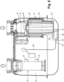
- the meter 1 comprises a housing 4 which includes an input connector 5 and an output connector 6.
- the input connector 5 makes it possible to connect to the meter 1 a pipe 7 which connects the distribution network 3 to the meter 1.
- the output connector 6 allows a pipe 8 to be connected to the meter 1 which connects the meter 1 to the installation 2.
- the position of counter 1 shown on the Figure 1 is the nominal position of meter 1, that is, the operating position it occupies when in service and correctly positioned.
- a positioning term is used in relation to an object (upper, lower, etc.), we are referring to the nominal, in-service position of that object.
- the input connector 5 and the output connector 6 are located on an upper face 9 of the housing 4 of the meter 1.
- a tank 10 is defined inside the housing 4.
- the inlet connector 5 opens into the tank 10.
- the meter 1 comprises an electromechanical valve 11 and a dust filter 12, which are positioned in the tank 10.
- the electromechanical valve 11 is a ball valve which comprises a conduit 14 and a ball 15 positioned in the conduit 14.
- the angular position of the ball 15 can be controlled remotely, which makes it possible to cut off, limit or restore the flow of gas supplied to the installation 2.
- Valve 11 is connected to inlet connector 5.
- the dust filter 12 will be described in detail below.
- the inlet connector 5, the conduit 14 of the valve 11 and the filter 12 extend successively, from top to bottom, along a vertical axis X1.
- the meter further comprises a measuring module 16.
- the measuring module 16 comprises a measuring conduit 17, a processing unit 18 and two ultrasonic transducers 19 (shown schematically in the Figure 1 and in positions not representative of reality).
- the processing unit 18 is located outside the tank 10. It is integrated into an electronic card of the meter 1, which is not necessarily dedicated solely to flow measurement.
- the processing unit 18 comprises at least one processing component (electronic and/or software), which is for example a “generalist” processor, a processor specialized in signal processing (or DSP, for Digital Signal Processor ), a microcontroller, or a programmable logic circuit such as an FPGA (for Field Programmable Gate Arrays ) or an ASIC (for Application Specific Integrated Circuit ).
- the processing unit 18 also comprises an excitation signal generator, and a signal receiver.
- the measuring module 16 operates as follows. Each ultrasonic transducer 19 successively acts as a transmitter and a receiver.
- the processing unit 18 generates an electrical excitation signal and applies it to the terminals of a transmitting transducer.
- the transmitter transmits an ultrasonic signal into the measuring conduit 17, which is captured by the receiver after having traveled a path of predefined length in the measuring conduit 17.
- the receiving transducer in turn becomes a transmitter and transmits an ultrasonic signal, which is captured by the other transducer after having traveled the same path, in the opposite direction.
- the processing unit 18 deduces from the received signals the speed of the gas and therefore the flow rate of the gas.
- the output of the measuring conduit 17 is connected to the output connector 6.
- the longitudinal axis of the measuring duct 17 is a vertical axis X2, parallel to the axis X1.
- the measuring conduit 17 and the output connector 6 extend successively, from bottom to top, along the axis X2.
- the gas enters meter 1 via inlet connector 5. It passes into conduit 14 of valve 11, then into filter 12, then into tank 10. It then enters measuring conduit 17 and leaves meter 1 via outlet connector 6.
- the dust filter 12 is therefore installed in the meter 1 upstream of the measuring module 16.
- upstream and downstream are defined in relation to the direction of gas flow in the meter 1.
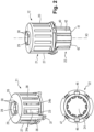
- the filter 12 comprises a housing 20 comprising a first envelope 21 and a second envelope 22, which are two separate housing elements.
- first chamber 23 Inside the housing 20 are defined a first chamber 23 and a second chamber 24.
- the first chamber 23 is located inside the first envelope 21 and the second chamber 24 is located inside the second envelope 21.
- the filter 12 When the filter 12 is installed in the meter 1, the first envelope 21, and therefore the first chamber 23, are located above the second envelope 22, and therefore the second chamber 24.
- the first envelope 21 comprises an upper face 26 and a first portion 27 of generally cylindrical shape.
- the upper face 26 comprises in its center a circular hole 28 forming an inlet orifice.
- a rib 29 of circular shape extends around the hole 28, at its circumference, projecting vertically from the upper face 26.
- a plurality of radial protrusions 30, here four radial protrusions 30, regularly distributed, extend from a free end of the rib 29 towards the outside (opposite the hole 28).
- the lower end of the conduit 14 of the valve 11 includes at its opening grooves 32 (visible only on the Figure 6 ), in this case four grooves 32, formed inside the conduit 14 and which extend along a circumference of the opening.
- the rib 29 and the radial protrusions 30 make it possible to fix the filter 12 to the lower end of the conduit 14 via a bayonet fitting.
- the filter 12 is positioned under the valve 11, the radial protrusions 30 of the rib 29 of the first casing 21 are inserted into the grooves 32, and the filter 12 is turned a quarter turn around its longitudinal axis X3 (which coincides with the axis X1 when the filter 12 is installed in the meter 1).
- the housing 20 also comprises outlet orifices 34 made at the level of the first chamber 23.
- the outlet orifices 34 are formed in the first portion 27 (of generally cylindrical shape).
- the outlet orifices 34 are of longitudinal shape along a height of the first portion 27: the length of the outlet orifices 34 is parallel to the axis X3.
- the outlet orifices 34 are positioned all around the first portion 27.
- the first envelope 21 further comprises a plurality of tabs 36, here two tabs 36, formed in the thickness of the first portion 27 and along a length thereof.
- Each tab 36 extends from the upper face 26 of the first envelope 21 to the end free from the first envelope 21, opposite the upper face 26.
- the free end of each tab 36 comprises a hook 37 allowing the first envelope 21 and the second envelope 22 to be fixed by elastic fitting.
- the outlet orifices 34 are defined between bars 38 which extend from the upper face 26 of the first casing 21 to its free end.
- the outlet orifices 34 are recesses made in the first portion 27 between the bars 38.
- the two tabs 36 also play the role of bars, but are wider than the other bars 36.
- the second casing 22 for its part, comprises a second portion 40, of generally cylindrical shape, and a lower face 41, forming the bottom of the second chamber 24, and therefore of the housing 20 of the filter 12.
- the second chamber 24 is located inside the second portion 40.
- the second portion 40 comprises lateral reinforcements 42 which extend longitudinally along the height of the second portion 40.
- the second envelope 22 further comprises a plurality of branches 43 which extend from a circumference of an end 49 of the second portion 40 opposite the lower face 41, and which are distributed regularly over the circumference of said end 49.
- the branches 43 are parallel to the longitudinal axis of the second envelope 22.
- the end portion 44 of each branch 43, at the level of the free end of the branch 43, has an external surface sloping and inclined towards the free end so that the thickness of the end portion 44 gradually reduces.
- the end 49 of the second portion 40 of the second casing 22 has a collar shape which comprises two holes 46 and four grooves 47 which extend along the collar and therefore along the external circumference of the end 49 of the second portion 40.
- the filter medium 50 for its part, has a tubular shape comprising a hollow central portion. Its longitudinal axis coincides with that of the first casing 21 and with the longitudinal axis X3 of the filter 12 when the filter 12 is assembled. The height of the filter medium 50 is equal to that of the first portion 27 of the first casing 21.
- the assembly of the filter 12 is carried out in the following manner.
- the filter medium 50 is slipped onto the second casing 22 so that the branches 43 of the second casing 22 are inserted into the hollowed-out central portion of the filter medium 50.
- the reduction in thickness of the free ends of the branches 43 facilitates this insertion.
- the first casing 21 covers the filter medium 50.
- the hooks 37 of the tabs 36 of the first casing 21 penetrate into the holes 46 of the collar of the second casing 22, which makes it possible to fix the first casing 21 and the second casing 22 together by elastic fitting.
- the edge of the free end of the first casing 21 is positioned in the grooves 47.
- the branches 43 compress the filter media 50 against the internal wall of the first portion 27 of the first casing 21.
- the filter 12 is integrated into the meter 1 by being fixed to the valve 11 using the bayonet mounting.
- the bayonet mounting allows easy and quick integration of the filter 12 into the meter 1 while having locking security and resistance to vibrations and drops.
- the gas after entering the meter 1, passes through the conduit 14 of the valve 11 and then enters the filter 12 via the inlet orifice 28 of the first casing 21 of the housing 20. It passes through the filter medium 50 and exits the filter 12 via the outlet orifices 34 of the first casing 21. The gas then spreads into the tank 10 and enters the measuring conduit 17 of the measuring module 16. All the gas which enters the measuring module 16 has therefore been filtered. The gas leaves the meter 1 via the outlet orifice 6.
- the lightest dust particles are left in suspension and are filtered by the filter media 50.
- the filter media 50 here is a synthetic media filter.
- Class G3 is a European standard used to classify air filters according to their filtering capacity. It indicates that the filter has a minimum filtering efficiency of 50% for particles between 0.3 and 1 micron. This means that if 100% of particles of this size are present in the air, at least 50% will be retained by the filter.
- Class G4 is a European standard used to classify air filters according to their filtering capacity. It indicates that the filter has a minimum filtering efficiency of 85% for particles between 0.3 and 1 micron. This means that if 100% of particles of this size are present in the air, at least 85% will be retained by the filter.
- a standard dust resistance test was carried out in a certified laboratory to evaluate the performance of filter 12. This test consists of measuring the accuracy of meter 1 in the presence of 20 grams of dust (standard requirement).
- the error curve as a function of flow rate must remain within a metrological template defined by an upper limit curve Ch and a lower limit curve Cb.
- Curve C1 represents the evolution of the error as a function of the flow rate before the normative dust resistance test, i.e. before the introduction of dust.
- Curve C2 represents the evolution of the error as a function of the flow rate after the introduction of dust. We see that the accuracy has been very slightly degraded by the test. The metrological error is degraded on average by 0.65% but remains within the metrological template and is therefore compliant with the standard.
- the EN 14236 standard is a European standard that defines the requirements for ultrasonic gas meters. It covers performance requirements, safety requirements, reliability requirements, and electromagnetic compatibility requirements for ultrasonic gas meters. Performance requirements include measurement accuracy, measurement stability, operating temperature, operating pressure, electromagnetic compatibility, and dust resistance, and safety requirements include electrical safety and fire safety requirements.
- G6 type meters have a minimum flow rate of 0.06 m3 /h and a maximum flow rate of 10 m3 /h.
- G4 type meters have a minimum flow rate of 0.04 m3 /h and a maximum flow rate of 6 m3 /h.
- G6 meters are suitable for higher gas consumption than G4 meters.
- the pressure drop may increase after the standard “dust resistance” test but must remain below 2.2 mbar at the maximum flow rate.
- the reference pressure drop at Qmax (maximum flow rate) is: 1 mbar.
- the pressure drop after the “dust resistance” test at Qmax (maximum flow rate) is: 1.05 mbar.
- the filter comprises a magnet 52. It could also comprise a plurality of magnets 52.
- the magnet(s) 52 are located in the second chamber 24.
- the filter 12 comprises a single magnet 52 which is positioned on the bottom of the second chamber 24, being glued thereto. Any fixing means can be used to fix the magnet(s).
- the addition of one or more magnets 52 in the second chamber 24 increases the performance of the filter 12 by increasing the holding force of the dust particles.
- the magnet(s) 52 create a magnetic field that attracts metallic dust particles, such as iron particles (knowing that 92% of the dust used for certification tests in a gas meter is iron particles).
- the magnets 52 can also help reduce the pressure drop due to the accumulation of dust particles on the filter, which can also improve the filter's performance.
- the meter 1 integrates a pressure measuring device 54.
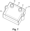
- the pressure measuring device 54 comprises a housing 55 inside which a differential pressure sensor 56 is integrated.
- the housing 55 comprises an upper face comprising a first pressure port 57 and a second pressure port 58.
- the housing 55 is positioned so that the first pressure port 57 opens into the second chamber 24 of the filter 12, and so that the second pressure port 58 opens into the tank 10 outside the filter 12 and downstream of the filter 12.
- the differential pressure sensor 56 includes a first sensitive cell that is in fluid communication with the second chamber 24 via the first pressure port 57, and a second sensitive cell that is in fluid communication with the vessel 10 via the second pressure port 58.
- the differential pressure sensor 56 is connected to the processing unit 18 of the meter 1 (which is located outside the tank 10) by the wires 59.
- the differential pressure sensor 56 allows the evolution of the pressure drop to be measured.
- a first pressure measurement P1 is acquired, taken by the first sensitive cell, and a second pressure measurement P2 is taken by the second sensitive cell, for several flow rate values.
- the corresponding pressure drop ( ⁇ P: P1-P2) is then calculated for each flow rate value.
- ⁇ P pressure drop values will be used as a reference to be able to monitor the evolution of the pressure drop during the life of meter 1.
- the reference pressure drop ⁇ P0 at 10000 l/h, measured during the calibration of meter 1 is for example equal to 1 mbar.
- the processing unit 18 compares with a reference threshold a pressure difference between a first pressure measurement produced by the first sensitive cell and a second pressure measurement produced by the second sensitive cell, and produces an alarm message if the pressure difference is greater than said reference threshold.
- the shape of the filter and that of the various elements constituting it may of course be different from those described here.
- the filter When the filter is integrated into the meter, its longitudinal axis is not necessarily positioned vertically; it could be inclined relative to the vertical.
- the materials used for the filter media and housing may vary from those described here.
Landscapes
- Physics & Mathematics (AREA)
- Fluid Mechanics (AREA)
- General Physics & Mathematics (AREA)
- Chemical & Material Sciences (AREA)
- Chemical Kinetics & Catalysis (AREA)
- Dispersion Chemistry (AREA)
- Health & Medical Sciences (AREA)
- Life Sciences & Earth Sciences (AREA)
- Analytical Chemistry (AREA)
- Biochemistry (AREA)
- General Health & Medical Sciences (AREA)
- Immunology (AREA)
- Pathology (AREA)
- Electromagnetism (AREA)
- Measuring Volume Flow (AREA)
Claims (14)
- Staubfilter (12) für den Einbau in einen Gaszähler (1) stromaufwärts eines Messmoduls (16) zur Durchflussmessung eines Gases, wobei der Filter (12) ein Gehäuse (20) enthält, in welchem eine erste Kammer (23) und eine zweite Kammer (24) definiert sind, wobei sich die erste Kammer oberhalb der zweiten Kammer befindet, wenn der Filter in dem Zähler eingebaut ist, wobei das Gehäuse eine Einlassöffnung (28) und Auslassöffnungen (34), die im Bereich der ersten Kammer ausgebildet sind, umfasst, wobei ein Filtermedium (50) in der ersten Kammer eingebaut ist, wobei der Filter somit derart ausgelegt ist, dass, wenn er in dem Zähler eingebaut ist, das Gas über die Einlassöffnung in den Filter eintritt, das Filtermedium durchströmt und über die Auslassöffnungen aus dem Filter austritt, währenddessen sich im Gas enthaltene Staubpartikel auf einem Boden der zweiten Kammer (24) absetzen, wobei das Gehäuse (20) zwei aneinander fixierte Hüllen umfasst, eine erste Hülle (21), in deren Innerem sich die erste Kammer (23) befindet, und eine zweite Hülle (22), in deren Innerem sich die zweite Kammer (24) befindet, wobei die erste Hülle eine Oberseite (26) umfasst, in welcher die Einlassöffnung (28) ausgebildet ist, und wobei der Filter dadurch gekennzeichnet ist, dass die erste Hülle (21) einen im Allgemeinen zylindrisch ausgebildeten, ersten Abschnitt (27) umfasst, in welchem die Auslassöffnungen (34) ausgebildet sind.
- Staubfilter nach Anspruch 1, wobei das Filtermedium (50) eine rohrförmige Form mit einem hohlen Mittelteil aufweist und eine Längsachse besitzt, die mit einer Längsachse des Filters zusammenfällt, wobei die zweite Hülle (22) einen im Allgemeinen zylindrisch ausgebildeten, zweiten Abschnitt (40) und eine den Boden der zweiten Kammer (24) bildende Unterseite (41) umfasst, wobei die zweite Hülle ferner eine Mehrzahl von Schenkeln (43) umfasst, die sich über den Umfang hinweg von einem der Unterseite (41) entgegengesetzten Ende (49) des zweiten Abschnitts (40) weg erstrecken, wobei die Schenkel parallel zu einer Längsachse des Filters verlaufen, wobei der Filter derart ausgelegt ist, dass sich in seinem zusammengebauten Zustand die Schenkel in den hohlen Mittelteil des Filtermediums hinein erstrecken und dabei besagtes Filtermedium an eine Innenwand des ersten Abschnitts (27) der ersten Hülle (21) andrücken.
- Staubfilter nach einem der vorhergehenden Ansprüche, wobei die erste Hülle (21) Laschen (36) umfasst, die in der Dicke des ersten Abschnitts (27) und gemäß einer Länge desselben ausgebildet sind, wobei sich jede Lasche von der Oberseite (26) der ersten Hülle (21) aus bis zu einem der Oberseite entgegengesetzten Ende der ersten Hülle erstreckt, wobei das freie Ende jeder Lasche einen Haken (37) umfasst, der dazu dient, die erste Hülle und die zweite Hülle durch eine elastische Schnappverbindung aneinander zu fixieren.
- Staubfilter nach Anspruch 3, wobei die Auslassöffnungen (34) an die Laschen (36) angrenzende, erste Öffnungen (34a) und an besagte Laschen nicht angrenzende, zweite Öffnungen (34b) umfassen, wobei die ersten Öffnungen breiter als die zweiten Öffnungen ausgebildet sind.
- Staubfilter nach Anspruch 3, wobei das Ende (49) des zweiten Abschnitts (40) eine kragenartige Form mit Löchern (46) aufweist, in welche die Haken (37) der Laschen (36) der ersten Hülle (21) einschnappen.
- Staubfilter nach einem der vorhergehenden Ansprüche, wobei die Oberseite (26) des Gehäuses eine Rippe (29) enthält, welche die Einlassöffnung (28) umgibt und mit radialen Vorsprüngen (30) versehen ist, die dafür ausgelegt sind, den Filter durch einen Bajonettverschluss in dem Zähler (1) zu befestigen.
- Staubfilter nach einem der vorhergehenden Ansprüche, ferner umfassend einen Magneten (52), der an dem Boden der zweiten Kammer (24) positioniert ist und dafür ausgelegt ist, metallische Staubpartikel anzuziehen.
- Staubfilter nach einem der vorhergehenden Ansprüche, wobei das Gehäuse (20) aus Polyoxymethylen gefertigt ist.
- Staubfilter nach einem der vorhergehenden Ansprüche, wobei es sich bei dem Filtermedium (50) um ein Polyestermedium handelt.
- Gaszähler umfassend ein Messmodul (16) zur Durchflussmessung eines Gases und einen Staubfilter (12) nach einem der vorhergehenden Ansprüche, wobei der Filter stromaufwärts des Messmoduls (16) eingebaut ist, sodass das gesamte Gas, das in das Messmodul einströmt, zuvor von dem Filter gefiltert worden ist.
- Gaszähler nach Anspruch 10, umfassend einen Einlassverbinder (5), über welchen das Gas in den Zähler eintritt, und einen Auslassverbinder (6), über welchen das Gas aus dem Zähler austritt, wobei der Zähler derart ausgelegt ist, dass, wenn der Zähler in einer Nennposition eingebaut ist, sich der Einlassverbinder und der Filter entlang einer Vertikalachse (X1) hintereinander von oben nach unten erstrecken während sich eine Messleitung (17) des Messmoduls (16) und der Auslassverbinder (6) entlang einer zweiten Vertikalachse (X2) hintereinander von unten nach oben erstrecken.
- Gaszähler nach Anspruch 11, ferner umfassend ein zwischen dem Einlassverbinder (5) und dem Filter (12) positioniertes elektromechanisches Ventil (11), an welchem der Filter befestigt ist.
- Gaszähler nach einem der Ansprüche 10 bis 12, ferner enthaltend eine Druckmesseinrichtung (54), die ein Gehäuse (55) mit integriertem Differenzdrucksensor (56) umfasst, wobei das Gehäuse einen in die zweite Kammer (24) des Filters (12) mündenden, ersten Druckanschluss (57) und einen in einen Behälter (10) des Zählers außerhalb des Filters mündenden, zweiten Druckanschluss (58) umfasst.
- Gaszähler nach Anspruch 13, wobei der Zähler eine Verarbeitungseinheit (18) umfasst, die dafür ausgelegt ist, eine Druckdifferenz zwischen einem ersten Druckmesswert, der von einer ersten empfindlichen Zelle des Differenzdrucksensors (56) erzeugt wird, welche über den ersten Druckanschluss (57) in Fluidverbindung mit der zweiten Kammer (24) steht, und einem zweiten Druckmesswert, der von einer zweiten empfindlichen Zelle des Differenzdrucksensors (56) erzeugt wird, welche über den zweiten Druckanschluss (58) in Fluidverbindung mit dem Behälter (10) steht, mit einem Referenzschwellenwert zu vergleichen und eine Alarmmeldung zu erzeugen, wenn die Druckdifferenz besagten Referenzschwellenwert übersteigt.
Applications Claiming Priority (1)
| Application Number | Priority Date | Filing Date | Title |
|---|---|---|---|
| FR2301853A FR3146202A1 (fr) | 2023-02-28 | 2023-02-28 | Filtre anti-poussière pour compteur de gaz |
Publications (2)
| Publication Number | Publication Date |
|---|---|
| EP4425115A1 EP4425115A1 (de) | 2024-09-04 |
| EP4425115B1 true EP4425115B1 (de) | 2025-04-23 |
Family
ID=86331918
Family Applications (1)
| Application Number | Title | Priority Date | Filing Date |
|---|---|---|---|
| EP24157889.7A Active EP4425115B1 (de) | 2023-02-28 | 2024-02-15 | Staubfilter für gaszähler |
Country Status (6)
| Country | Link |
|---|---|
| US (1) | US20240288295A1 (de) |
| EP (1) | EP4425115B1 (de) |
| CN (1) | CN118565580A (de) |
| AU (1) | AU2024200974A1 (de) |
| ES (1) | ES3032337T3 (de) |
| FR (1) | FR3146202A1 (de) |
Families Citing this family (2)
| Publication number | Priority date | Publication date | Assignee | Title |
|---|---|---|---|---|
| US11067464B2 (en) | 2019-01-18 | 2021-07-20 | Mueller International, Llc | Wet barrel hydrant with pressure monitoring and leak detection |
| US11313748B2 (en) * | 2019-01-18 | 2022-04-26 | Mueller International, Llc | Pressure monitor housing with cap-engaging projection |
Family Cites Families (24)
| Publication number | Priority date | Publication date | Assignee | Title |
|---|---|---|---|---|
| US5220830A (en) * | 1991-07-09 | 1993-06-22 | Honeywell Inc. | Compact gas flow meter using electronic microsensors |
| FR2721360B1 (fr) * | 1994-06-17 | 1996-08-02 | Schlumberger Ind Sa | Oscillateur fluidique et procédé de mesure d'une quantité volumique de fluide s'écoulant dans un tel oscillateur fluidique. |
| FR2755232B1 (fr) * | 1996-10-28 | 1998-12-04 | Schlumberger Ind Sa | Compteur a gaz a resistance amelioree a l'empoussierage |
| FR2772915B1 (fr) * | 1997-12-22 | 2000-01-28 | Inst Francais Du Petrole | Methode et dispositif de debitmetrie polyphasique |
| DE10131108A1 (de) * | 2001-06-27 | 2003-01-09 | Mann & Hummel Filter | Filterelement mit Drainagerohr |
| JP2004101303A (ja) * | 2002-09-06 | 2004-04-02 | Yazaki Corp | ガスメータおよびその取付構造ならびにガスメータの組立方法 |
| US20060207234A1 (en) * | 2005-03-18 | 2006-09-21 | Ward Bennett C | Coalescing filter elements comprising self-sustaining, bonded fiber structures |
| JP2014157017A (ja) * | 2011-06-10 | 2014-08-28 | Panasonic Corp | ガスメータ |
| JP2013044533A (ja) * | 2011-08-22 | 2013-03-04 | Panasonic Corp | ガスメータ |
| EP2813824B1 (de) * | 2013-06-12 | 2019-04-17 | Itron GmbH | Gaszähler und Partikelfalle |
| JP2016174988A (ja) * | 2015-03-18 | 2016-10-06 | 株式会社東芝 | 集塵装置及び集塵システム |
| NO341668B1 (en) * | 2016-01-07 | 2017-12-18 | Waertsilae Oil & Gas Systems As | Filter device and system comprising said filter device |
| CN206027303U (zh) * | 2016-08-29 | 2017-03-22 | 南京中能瑞华电气有限公司 | 一种用于含尘气流过滤的过滤器 |
| CN110121625B (zh) * | 2016-12-22 | 2021-09-14 | 基伊埃工程技术股份有限公司 | 具有过滤器单元的改进入口装置的粉末干燥系统及对此系统的过滤器单元进行操作的方法 |
| IT201800006413A1 (it) * | 2018-06-18 | 2019-12-18 | Struttura di misuratore di gas | |
| JP2021038930A (ja) * | 2019-08-30 | 2021-03-11 | オムロン株式会社 | ガスメータ |
| CN210221166U (zh) * | 2019-09-19 | 2020-03-31 | 卓度计量技术(深圳)有限公司 | 一种气体流量计 |
| US11754429B2 (en) * | 2020-11-11 | 2023-09-12 | Honeywell International Inc. | Multifunctional dust trap |
| US20220146298A1 (en) * | 2020-11-11 | 2022-05-12 | Honeywell International Inc. | Ageing and dust detection in a meter |
| CN112683353A (zh) * | 2020-12-14 | 2021-04-20 | 浙江荣鑫智能仪表股份有限公司 | 一种超声波燃气表的内置过滤系统 |
| CN215261933U (zh) * | 2021-07-29 | 2021-12-21 | 卓度计量技术(深圳)有限公司 | 气体流量计 |
| CN217032645U (zh) * | 2022-03-21 | 2022-07-22 | 天津加海仪表成套设备有限公司 | 一种气体腰轮流量计量箱 |
| EP4502549A4 (de) * | 2022-03-30 | 2025-07-09 | Panasonic Ip Man Co Ltd | Staubsammeladapter |
| CN217236890U (zh) * | 2022-05-10 | 2022-08-19 | 杭州合一计量技术有限公司 | 具有耐污染结构的超声波燃气表 |
-
2023
- 2023-02-28 FR FR2301853A patent/FR3146202A1/fr active Pending
-
2024
- 2024-02-15 ES ES24157889T patent/ES3032337T3/es active Active
- 2024-02-15 EP EP24157889.7A patent/EP4425115B1/de active Active
- 2024-02-15 AU AU2024200974A patent/AU2024200974A1/en active Pending
- 2024-02-27 US US18/589,230 patent/US20240288295A1/en active Pending
- 2024-02-28 CN CN202410220899.1A patent/CN118565580A/zh active Pending
Also Published As
| Publication number | Publication date |
|---|---|
| US20240288295A1 (en) | 2024-08-29 |
| FR3146202A1 (fr) | 2024-08-30 |
| ES3032337T3 (en) | 2025-07-17 |
| AU2024200974A1 (en) | 2024-09-12 |
| CN118565580A (zh) | 2024-08-30 |
| EP4425115A1 (de) | 2024-09-04 |
Similar Documents
| Publication | Publication Date | Title |
|---|---|---|
| EP4425115B1 (de) | Staubfilter für gaszähler | |
| EP0566479B1 (de) | Verschmutzungsdetektor für Luftfilter | |
| WO2021209456A1 (fr) | Surveillance de l'huile d'un dispositif de lubrification | |
| EP3625549B1 (de) | Sensor zur messung der partikelkonzentration in der luft | |
| FR2862755A1 (fr) | Capteur de pression | |
| EP1064522A1 (de) | Gaszähler mit staubschutzfiltern | |
| FR3006906A1 (fr) | Garniture de filtre a liquide notamment de filtre a carburant | |
| EP4425114B1 (de) | Staubfilter für gaszähler | |
| EP3625548A1 (de) | Sensor zur messung der konzentration von partikeln in der luft | |
| FR2492972A1 (fr) | Debitmetre | |
| EP0060736B1 (de) | Vorrichtung zum Festhalten einer Skala an einem Gehäuse eines Kilometerzählers oder dergleichen | |
| EP0807822B1 (de) | Messung eines aus einer Oberfläche austretenden Gasstromes | |
| FR2496414A1 (fr) | Cartouche de filtrage de fumee pour porte-cigarette | |
| EP3690168A1 (de) | Filterblock für schwimmbad, der mit einem messsystem des verstopfungsgrads und/oder verstopfungszustands eines filters ausgestattet ist | |
| FR3104034A1 (fr) | Dispositif d’entrée d’air munie d’un filtre pour une ventilation à simple flux pour bâtiment | |
| EP4039917B1 (de) | Drahtloser drucksensor und entsprechende vorrichtung zur überwachung eines pools | |
| EP0607089B1 (de) | Turbinenlager für Flüssigkeitszähler | |
| FR2853069A3 (fr) | Debitmetre selon le principe du vortex | |
| FR3167421A1 (fr) | Ensemble et procede pour la detection de limaille | |
| EP3527955A1 (de) | Fluidischer oscillator-durchflussmessgerät mit verbesserter durchflusskonditionierer | |
| WO1998008064A1 (fr) | Turbine debitmetrique | |
| FR2757573A1 (fr) | Filtre et dispositif d'alimentation en carburant equipe d'un tel filtre | |
| FR2860589A1 (fr) | Dispositif de detection de niveaux de liquide | |
| EP3305730A1 (de) | Vorrichtung zum auffangen von eisenhaltigen schlämmen, die ein magnetisches ablasssystem umfasst | |
| WO2024218152A1 (fr) | Dispositif de nettoyage d'une surface de détection d'un dispositif de détection |
Legal Events
| Date | Code | Title | Description |
|---|---|---|---|
| PUAI | Public reference made under article 153(3) epc to a published international application that has entered the european phase |
Free format text: ORIGINAL CODE: 0009012 |
|
| STAA | Information on the status of an ep patent application or granted ep patent |
Free format text: STATUS: REQUEST FOR EXAMINATION WAS MADE |
|
| 17P | Request for examination filed |
Effective date: 20240215 |
|
| AK | Designated contracting states |
Kind code of ref document: A1 Designated state(s): AL AT BE BG CH CY CZ DE DK EE ES FI FR GB GR HR HU IE IS IT LI LT LU LV MC ME MK MT NL NO PL PT RO RS SE SI SK SM TR |
|
| GRAP | Despatch of communication of intention to grant a patent |
Free format text: ORIGINAL CODE: EPIDOSNIGR1 |
|
| STAA | Information on the status of an ep patent application or granted ep patent |
Free format text: STATUS: GRANT OF PATENT IS INTENDED |
|
| RIC1 | Information provided on ipc code assigned before grant |
Ipc: B01D 46/24 20060101ALI20241108BHEP Ipc: G01F 15/12 20060101AFI20241108BHEP |
|
| INTG | Intention to grant announced |
Effective date: 20241120 |
|
| RBV | Designated contracting states (corrected) |
Designated state(s): AL AT BE BG CH CY CZ DE DK EE ES FI FR GB GR HR HU IE IS IT LI LT LU LV MC ME MK MT NL NO PL PT RO RS SE SI SK SM TR |
|
| GRAS | Grant fee paid |
Free format text: ORIGINAL CODE: EPIDOSNIGR3 |
|
| GRAA | (expected) grant |
Free format text: ORIGINAL CODE: 0009210 |
|
| STAA | Information on the status of an ep patent application or granted ep patent |
Free format text: STATUS: THE PATENT HAS BEEN GRANTED |
|
| AK | Designated contracting states |
Kind code of ref document: B1 Designated state(s): AL AT BE BG CH CY CZ DE DK EE ES FI FR GB GR HR HU IE IS IT LI LT LU LV MC ME MK MT NL NO PL PT RO RS SE SI SK SM TR |
|
| REG | Reference to a national code |
Ref country code: GB Ref legal event code: FG4D Free format text: NOT ENGLISH |
|
| REG | Reference to a national code |
Ref country code: CH Ref legal event code: EP |
|
| REG | Reference to a national code |
Ref country code: DE Ref legal event code: R096 Ref document number: 602024000069 Country of ref document: DE |
|
| REG | Reference to a national code |
Ref country code: IE Ref legal event code: FG4D Free format text: LANGUAGE OF EP DOCUMENT: FRENCH |
|
| REG | Reference to a national code |
Ref country code: ES Ref legal event code: FG2A Ref document number: 3032337 Country of ref document: ES Kind code of ref document: T3 Effective date: 20250717 |
|
| REG | Reference to a national code |
Ref country code: NL Ref legal event code: MP Effective date: 20250423 |
|
| PG25 | Lapsed in a contracting state [announced via postgrant information from national office to epo] |
Ref country code: NL Free format text: LAPSE BECAUSE OF FAILURE TO SUBMIT A TRANSLATION OF THE DESCRIPTION OR TO PAY THE FEE WITHIN THE PRESCRIBED TIME-LIMIT Effective date: 20250423 |
|
| REG | Reference to a national code |
Ref country code: AT Ref legal event code: MK05 Ref document number: 1788139 Country of ref document: AT Kind code of ref document: T Effective date: 20250423 |
|
| PG25 | Lapsed in a contracting state [announced via postgrant information from national office to epo] |
Ref country code: FI Free format text: LAPSE BECAUSE OF FAILURE TO SUBMIT A TRANSLATION OF THE DESCRIPTION OR TO PAY THE FEE WITHIN THE PRESCRIBED TIME-LIMIT Effective date: 20250423 Ref country code: PT Free format text: LAPSE BECAUSE OF FAILURE TO SUBMIT A TRANSLATION OF THE DESCRIPTION OR TO PAY THE FEE WITHIN THE PRESCRIBED TIME-LIMIT Effective date: 20250825 |
|
| REG | Reference to a national code |
Ref country code: LT Ref legal event code: MG9D |
|
| PG25 | Lapsed in a contracting state [announced via postgrant information from national office to epo] |
Ref country code: GR Free format text: LAPSE BECAUSE OF FAILURE TO SUBMIT A TRANSLATION OF THE DESCRIPTION OR TO PAY THE FEE WITHIN THE PRESCRIBED TIME-LIMIT Effective date: 20250724 Ref country code: NO Free format text: LAPSE BECAUSE OF FAILURE TO SUBMIT A TRANSLATION OF THE DESCRIPTION OR TO PAY THE FEE WITHIN THE PRESCRIBED TIME-LIMIT Effective date: 20250723 |
|
| PG25 | Lapsed in a contracting state [announced via postgrant information from national office to epo] |
Ref country code: PL Free format text: LAPSE BECAUSE OF FAILURE TO SUBMIT A TRANSLATION OF THE DESCRIPTION OR TO PAY THE FEE WITHIN THE PRESCRIBED TIME-LIMIT Effective date: 20250423 |
|
| PG25 | Lapsed in a contracting state [announced via postgrant information from national office to epo] |
Ref country code: BG Free format text: LAPSE BECAUSE OF FAILURE TO SUBMIT A TRANSLATION OF THE DESCRIPTION OR TO PAY THE FEE WITHIN THE PRESCRIBED TIME-LIMIT Effective date: 20250423 |
|
| PG25 | Lapsed in a contracting state [announced via postgrant information from national office to epo] |
Ref country code: HR Free format text: LAPSE BECAUSE OF FAILURE TO SUBMIT A TRANSLATION OF THE DESCRIPTION OR TO PAY THE FEE WITHIN THE PRESCRIBED TIME-LIMIT Effective date: 20250423 |
|
| PG25 | Lapsed in a contracting state [announced via postgrant information from national office to epo] |
Ref country code: AT Free format text: LAPSE BECAUSE OF FAILURE TO SUBMIT A TRANSLATION OF THE DESCRIPTION OR TO PAY THE FEE WITHIN THE PRESCRIBED TIME-LIMIT Effective date: 20250423 |
|
| PG25 | Lapsed in a contracting state [announced via postgrant information from national office to epo] |
Ref country code: RS Free format text: LAPSE BECAUSE OF FAILURE TO SUBMIT A TRANSLATION OF THE DESCRIPTION OR TO PAY THE FEE WITHIN THE PRESCRIBED TIME-LIMIT Effective date: 20250723 |
|
| PG25 | Lapsed in a contracting state [announced via postgrant information from national office to epo] |
Ref country code: IS Free format text: LAPSE BECAUSE OF FAILURE TO SUBMIT A TRANSLATION OF THE DESCRIPTION OR TO PAY THE FEE WITHIN THE PRESCRIBED TIME-LIMIT Effective date: 20250823 |
|
| PG25 | Lapsed in a contracting state [announced via postgrant information from national office to epo] |
Ref country code: LV Free format text: LAPSE BECAUSE OF FAILURE TO SUBMIT A TRANSLATION OF THE DESCRIPTION OR TO PAY THE FEE WITHIN THE PRESCRIBED TIME-LIMIT Effective date: 20250423 |
|
| PG25 | Lapsed in a contracting state [announced via postgrant information from national office to epo] |
Ref country code: DK Free format text: LAPSE BECAUSE OF FAILURE TO SUBMIT A TRANSLATION OF THE DESCRIPTION OR TO PAY THE FEE WITHIN THE PRESCRIBED TIME-LIMIT Effective date: 20250423 Ref country code: SM Free format text: LAPSE BECAUSE OF FAILURE TO SUBMIT A TRANSLATION OF THE DESCRIPTION OR TO PAY THE FEE WITHIN THE PRESCRIBED TIME-LIMIT Effective date: 20250423 |
|
| PG25 | Lapsed in a contracting state [announced via postgrant information from national office to epo] |
Ref country code: CZ Free format text: LAPSE BECAUSE OF FAILURE TO SUBMIT A TRANSLATION OF THE DESCRIPTION OR TO PAY THE FEE WITHIN THE PRESCRIBED TIME-LIMIT Effective date: 20250423 |
|
| PG25 | Lapsed in a contracting state [announced via postgrant information from national office to epo] |
Ref country code: EE Free format text: LAPSE BECAUSE OF FAILURE TO SUBMIT A TRANSLATION OF THE DESCRIPTION OR TO PAY THE FEE WITHIN THE PRESCRIBED TIME-LIMIT Effective date: 20250423 |
|
| REG | Reference to a national code |
Ref country code: DE Ref legal event code: R097 Ref document number: 602024000069 Country of ref document: DE |
|
| PG25 | Lapsed in a contracting state [announced via postgrant information from national office to epo] |
Ref country code: SK Free format text: LAPSE BECAUSE OF FAILURE TO SUBMIT A TRANSLATION OF THE DESCRIPTION OR TO PAY THE FEE WITHIN THE PRESCRIBED TIME-LIMIT Effective date: 20250423 |
|
| PLBE | No opposition filed within time limit |
Free format text: ORIGINAL CODE: 0009261 |
|
| STAA | Information on the status of an ep patent application or granted ep patent |
Free format text: STATUS: NO OPPOSITION FILED WITHIN TIME LIMIT |
|
| REG | Reference to a national code |
Ref country code: CH Ref legal event code: L10 Free format text: ST27 STATUS EVENT CODE: U-0-0-L10-L00 (AS PROVIDED BY THE NATIONAL OFFICE) Effective date: 20260304 |
|
| 26N | No opposition filed |
Effective date: 20260126 |
|
| PGFP | Annual fee paid to national office [announced via postgrant information from national office to epo] |
Ref country code: ES Payment date: 20260302 Year of fee payment: 3 |
|
| PGFP | Annual fee paid to national office [announced via postgrant information from national office to epo] |
Ref country code: BE Payment date: 20260121 Year of fee payment: 3 Ref country code: IT Payment date: 20260228 Year of fee payment: 3 |
|
| PGFP | Annual fee paid to national office [announced via postgrant information from national office to epo] |
Ref country code: FR Payment date: 20260121 Year of fee payment: 3 |