EP4424514A1 - Transportation device and recording device - Google Patents
Transportation device and recording device Download PDFInfo
- Publication number
- EP4424514A1 EP4424514A1 EP24160006.3A EP24160006A EP4424514A1 EP 4424514 A1 EP4424514 A1 EP 4424514A1 EP 24160006 A EP24160006 A EP 24160006A EP 4424514 A1 EP4424514 A1 EP 4424514A1
- Authority
- EP
- European Patent Office
- Prior art keywords
- filter
- section
- cleaning fluid
- reservoir tank
- discharge port
- Prior art date
- Legal status (The legal status is an assumption and is not a legal conclusion. Google has not performed a legal analysis and makes no representation as to the accuracy of the status listed.)
- Pending
Links
Images


Classifications
-
- B—PERFORMING OPERATIONS; TRANSPORTING
- B41—PRINTING; LINING MACHINES; TYPEWRITERS; STAMPS
- B41J—TYPEWRITERS; SELECTIVE PRINTING MECHANISMS, i.e. MECHANISMS PRINTING OTHERWISE THAN FROM A FORME; CORRECTION OF TYPOGRAPHICAL ERRORS
- B41J11/00—Devices or arrangements of selective printing mechanisms, e.g. ink-jet printers or thermal printers, for supporting or handling copy material in sheet or web form
- B41J11/007—Conveyor belts or like feeding devices
-
- B—PERFORMING OPERATIONS; TRANSPORTING
- B41—PRINTING; LINING MACHINES; TYPEWRITERS; STAMPS
- B41J—TYPEWRITERS; SELECTIVE PRINTING MECHANISMS, i.e. MECHANISMS PRINTING OTHERWISE THAN FROM A FORME; CORRECTION OF TYPOGRAPHICAL ERRORS
- B41J2/00—Typewriters or selective printing mechanisms characterised by the printing or marking process for which they are designed
- B41J2/005—Typewriters or selective printing mechanisms characterised by the printing or marking process for which they are designed characterised by bringing liquid or particles selectively into contact with a printing material
- B41J2/01—Ink jet
- B41J2/17—Ink jet characterised by ink handling
- B41J2/175—Ink supply systems ; Circuit parts therefor
- B41J2/17563—Ink filters
-
- B—PERFORMING OPERATIONS; TRANSPORTING
- B41—PRINTING; LINING MACHINES; TYPEWRITERS; STAMPS
- B41J—TYPEWRITERS; SELECTIVE PRINTING MECHANISMS, i.e. MECHANISMS PRINTING OTHERWISE THAN FROM A FORME; CORRECTION OF TYPOGRAPHICAL ERRORS
- B41J29/00—Details of, or accessories for, typewriters or selective printing mechanisms not otherwise provided for
- B41J29/17—Cleaning arrangements
Definitions
- the present disclosure relates to a transportation device and a recording device.
- JP-A-2007-15319 discloses a transportation device including a transportation belt for transporting a medium while supporting the medium, a reservoir tank capable of storing a cleaning fluid for cleaning the transportation belt, and a washing section for cleaning the transportation belt by using the cleaning fluid stored in the reservoir tank.
- the reservoir tank is provided with a discharge port for discharging the cleaning fluid.
- the reservoir tank is provided with a partition wall surrounding the outlet.
- a transportation device includes a transportation belt configured to transport the medium in a state of supporting the medium, a reservoir tank that is configured to contain a cleaning fluid for cleaning the transportation belt and that has a discharge port through which the contained cleaning fluid is dischargeable, a filter that is provided at a position covering the discharge port and that collects foreign matter included in the cleaning fluid contained in the reservoir tank, and a filter moving section configured to move the filter wherein the filter moving section is configured to move the filter such that a positional relationship between a predetermined region of the filter and the discharge port changes.
- a recording device includes a transportation belt configured to transport the medium in a state of supporting the medium, a recording section that performs recording by ejecting a liquid onto a medium transported by the transportation belt, a reservoir tank that is configured to contain a cleaning fluid for cleaning the transportation belt and that has a discharge port through which the contained cleaning fluid is dischargeable, a filter that is provided at a position covering the discharge port and that collects foreign matter included in the cleaning fluid contained in the reservoir tank, and a filter moving section configured to move the filter wherein the filter moving section is configured to move the filter such that a positional relationship between a predetermined region of the filter and the discharge port changes.
- a direction intersecting the vertical direction Z is referred to as a width direction X
- a direction intersecting the vertical direction Z and the width direction X is referred to as a length direction Y.
- the upward direction in the vertical direction Z is referred to as an upward direction Z1
- the downward direction in the vertical direction Z is referred to as a downward direction Z2.
- a recording device 11 may be an inkjet printer that performs recording on a medium 99 by ejecting ink, which is an example of liquid, onto the medium 99.
- the medium 99 is fabric, but may be, for example, paper.
- the recording device 11 includes a recording section 12.
- the recording section 12 is configured to perform recording on the medium 99 by ejecting liquid onto the medium 99.
- the recording section 12 performs the recording on the medium 99, which is transported by a transportation belt 17 (described later).
- the recording section 12 may be a head.
- the recording section 12 may be a serial head or a line head.
- the serial head is the head that scans the medium 99 in the width direction X.
- the line head is the head that records all at once in the width direction X.
- the recording section 12 includes a plurality of nozzles 13. Each of the plurality of nozzles 13 is configured to open in the downward direction Z2. Each of the plurality of nozzles 13 is configured to eject liquid.
- the recording device 11 includes a transportation device 14.
- the transportation device 14 is configured to transport the medium 99 in the transportation direction D.
- the transportation direction D may be along the length direction Y.
- the transportation device 14 may include a first roller 15 and a second roller 16.
- the first roller 15 is located upstream of the second roller 16 in the transportation direction D.
- the first roller 15 is located upstream of the recording section 12 in the transportation direction D.
- the second roller 16 is located downstream of the recording section 12 in the transportation direction D.
- the transportation device 14 includes the transportation belt 17.
- the transportation belt 17 is configured to transport the medium 99 in a state of supporting the medium 99.
- the transportation belt 17 is wound around a plurality of rollers.
- the transportation belt 17 is wound around the first roller 15 and the second roller 16. When the first roller 15 rotates, the transportation belt 17 moves along the first roller 15 and the second roller 16.
- the transportation belt 17 includes a support surface 18 that supports the medium 99.
- the support surface 18 is an outer peripheral surface of the transportation belt 17.
- the transportation belt 17 is, for example, a belt in which an adhesive is applied to the support surface 18.
- the medium 99 is adhered to the support surface 18 by an adhesive.
- the medium 99 may be adhered to the support surface 18 not only by the adhesive but also by, for example, an attraction force, an electrostatic force, an intermolecular force, or the like. In this way, the transportation belt 17 transports the medium 99 supported on the support surface 18 by moving along the first roller 15 and the second roller 16.
- the transportation belt 17 may be soiled by transporting the medium 99.
- the support surface 18 tends to become dirty.
- powder or fluff generated from the medium 99, dust in the air, a recording material from the recording section 12, or the like may adhere to the support surface 18.
- the support surface 18 is contaminated.
- the support surface 18 is contaminated, there is a risk that the contamination may be attached to the medium 99.
- the adhesive force of the support surface 18 with respect to the medium 99 may be weakened.
- the transportation device 14 includes a roller drive section 19.
- the roller drive section 19 is a driving source for rotating the plurality of rollers.
- the roller drive section 19 may be a motor.
- the roller drive section 19 is coupled to the first roller 15, but may be coupled to the second roller 16, or may be coupled to both the first roller 15 and the second roller 16.
- the roller drive section 19 rotates the first roller 15.
- the roller drive section 19 rotates the second roller 16 via the transportation belt 17 with the rotation of the first roller 15.
- the transportation device 14 includes a cleaning device 20.
- the cleaning device 20 is configured to clean the transportation belt 17. Specifically, the cleaning device 20 cleans the support surface 18 by contact with the support surface 18. Accordingly, the risk that dirt adheres to the medium 99 from the transportation belt 17 is reduced. In addition, the risk of weakening the adhesive force of the support surface 18 is reduced.
- the cleaning device 20 is positioned to contact the support surface 18 in an area through which the medium 99 does not pass.
- the region through which the medium 99 does not pass may be a region facing a portion of the support surface 18 that moves in the direction opposite to the transportation direction D. That is, the cleaning device 20 may be positioned so as to sandwich the recording section 12 and the transportation belt 17.
- the cleaning device 20 cleans the support surface 18 after supporting the medium 99. Specifically, the cleaning device 20 cleans the support surface 18 after the medium 99 is peeled off. In other words, the cleaning device 20 cleans the support surface 18 before the medium 99 is supported again.
- the transportation device 14 may include a position adjustment section 21.
- the cleaning device 20 may include the position adjustment section 21.
- the position adjustment section 21 moves the cleaning device 20 so as to adjust the distance between the support surface 18 and the cleaning device 20, but the transportation belt 17 may be moved so as to adjust the distance between the support surface 18 and the cleaning device 20, or both may be moved.
- the transportation device 14 includes a control section 22. That is, the recording device 11 includes the control section 22.
- the transportation device 14 may include another control section that controls the transportation device 14, separately from the control section 22 included in the recording device 11.
- the control section 22 controls the recording device 11.
- the control section 22 controls, for example, the recording section 12 and the transportation device 14.
- the control section 22 controls various operations executed by the recording device 11.
- the control section 22 is configured as a circuit that includes
- the configuration of the cleaning device 20 will be described in detail with reference to FIG. 2 .
- the cleaning device 20 may include a washing section 23. That is, the transportation device 14 may include the washing section 23. Further, the recording device 11 may include the washing section 23.
- the washing section 23 is configured to clean the transportation belt 17 using cleaning fluid 98 contained in a reservoir tank 32 (described later). That is, the cleaning fluid 98 is a liquid for cleaning the transportation belt 17.
- the cleaning fluid 98 is, for example, water, but may be another liquid.
- the washing section 23 may include a cleaning roller 24.
- the cleaning roller 24 cleans the support surface 18 by contact with the support surface 18.
- the cleaning roller 24 may be rotatably supported by a support tank 31 to be described later.
- the cleaning roller 24 is located in the upward direction Z1 of the reservoir tank 32.
- the cleaning roller 24 can touch the cleaning fluid 98 contained in the reservoir tank 32.
- the cleaning roller 24 cleans the transportation belt 17 using the cleaning fluid 98 contained in the reservoir tank 32.
- the cleaning fluid 98 flows down to the reservoir tank 32 after being used to clean the transportation belt 17 in the cleaning roller 24.
- the cleaning roller 24 may be provided with a first rotation shaft 25 and an absorb member 26.
- the first rotation shaft 25 is parallel to the shaft of the first roller 15 and the shaft of the second roller 16.
- the absorb member 26 is a member capable of absorbing the cleaning fluid 98.
- the absorb member 26 may be a sponge.
- the absorb member 26 is supported by the first rotation shaft 25.
- the absorb member 26 rotates together with the first rotation shaft 25.
- the absorb member 26 cleans the support surface 18 by contact with the support surface 18.
- the cleaning roller 24 may be movable between a position at which the absorb member 26 contacts the support surface 18 and a position at which the absorb member 26 does not contact the support surface 18.
- the washing section 23 may be provided with a brush roller 27.
- the brush roller 27 cleans the support surface 18 by contacting the support surface 18.
- the brush roller 27 may be rotatably supported by the support tank 31 (described later).
- the brush roller 27 is located in the upward direction Z1 of the reservoir tank 32.
- the brush roller 27 can touch the cleaning fluid 98 contained in the reservoir tank 32.
- the brush roller 27 cleans the transportation belt 17 using the cleaning fluid 98 contained in the reservoir tank 32.
- the cleaning fluid 98 flows down to the reservoir tank 32 after being used to clean the transportation belt 17 in the brush roller 27. That is, the cleaning fluid 98 is used to clean the transportation belt 17 in the washing section 23, and then flows down to the reservoir tank 32.
- the brush roller 27 may include a second rotation shaft 28 and a brush 29.
- the second rotation shaft 28 is parallel to the first rotation shaft 25.
- the brush 29 is supported by the second rotation shaft 28.
- the brush 29 extends radially from the second rotation shaft 28 when viewed from the axial direction of the second rotation shaft 28.
- the brush 29 rotates together with the second rotation shaft 28.
- the brush 29 cleans the support surface 18 by contact with the support surface 18.
- the brush roller 27 may be movable between a position where the brush 29 contacts the support surface 18 and a position where the brush 29 does not contact the support surface 18.
- the brush roller 27 may be provided at a position shifted from the cleaning roller 24 in the transportation direction D.
- the brush roller 27 comes into contact with a partial region of the support surface 18 before the cleaning roller 24 comes into contact with the support surface 18.
- the cleaning device 20 includes a cleaning fluid feeder 30.
- the cleaning fluid feeder 30 can contain the cleaning fluid 98.
- the cleaning fluid feeder 30 is configured to supply the contained cleaning fluid 98 to the cleaning roller 24 and the brush roller 27.
- the cleaning fluid feeder 30 may include the support tank 31.
- the cleaning fluid feeder 30 includes the reservoir tank 32. That is, the transportation device 14 includes the reservoir tank 32. Further, the recording device 11 includes the reservoir tank 32.
- the cleaning fluid feeder 30 may include a supply tank 33, a first supply pipe 34, and a supply valve 35.
- the cleaning fluid feeder 30 may include a first discharge pipe 36 and a first discharge valve 37.
- the cleaning fluid feeder 30 may include a second discharge pipe 38 and a second discharge valve 39.
- the cleaning fluid feeder 30 may include a recirculation section 40. That is, the transportation device 14 may include the recirculation section 40.
- the recording device 11 may include the recirculation section 40.
- the recirculation section 40 may include a third discharge pipe 41, a first pump 42, a recirculation tank 43, a second supply pipe 44, and a second pump 45.
- the support tank 31 is configured to support the cleaning roller 24 and the brush roller 27.
- the support tank 31 includes a bottom section 31A and a side section 31B.
- the bottom section 31A constitutes the bottom surface of the support tank 31.
- the side section 31B constitutes a side surface of the support tank 31.
- the support tank 31 may house the reservoir tank 32.
- the cleaning roller 24 and the brush roller 27 may be mounted on the support tank 31.
- the support tank 31 can contain the cleaning fluid 98 overflowing from the reservoir tank 32.
- the support tank 31 includes a first outlet 50.
- the first outlet 50 is provided on the bottom section 31A, but may be provided on the side section 31B.
- the first outlet 50 is configured to communicate with the first discharge pipe 36.
- the first outlet 50 is an opening to discharge the cleaning fluid 98 that has overflowed from the reservoir tank 32 to the support tank 31 via the first discharge pipe 36. That is, the first outlet 50 can discharge the cleaning fluid 98 contained in the support tank 31.
- the discharge direction in which the cleaning fluid 98 is discharged from the first outlet 50 is a direction toward the downward direction Z2, but may be a direction toward the horizontal direction.
- the first discharge pipe 36 is a flow path for discharging the cleaning fluid 98 contained in the support tank 31 as waste liquid.
- the first discharge pipe 36 may be a flow path for discharging the cleaning fluid 98 contained in the support tank 31 to a waste liquid tank (not shown) as waste liquid.
- the first discharge valve 37 is provided in the first discharge pipe 36. The first discharge valve 37 can open and close the first discharge pipe 36. When the first discharge valve 37 is opened, the discharge of the cleaning fluid 98 stored in the support tank 31 is started, and when the first discharge valve 37 is closed, the discharge of the cleaning fluid 98 stored in the support tank 31 is stopped.
- the reservoir tank 32 can contain the cleaning fluid 98.
- the reservoir tank 32 includes a bottom section 32A, a first side section 32B, and a second side section 32C.
- the bottom section 32A constitutes a bottom surface of the reservoir tank 32.
- the first side section 32B constitutes a first side surface of the reservoir tank 32.
- the second side section 32C constitutes a second side surface of the reservoir tank 32.
- the reservoir tank 32 houses a part of the cleaning roller 24. Specifically, the reservoir tank 32 houses the bottom edge portion of the cleaning roller 24. The reservoir tank 32 can supply the contained the cleaning fluid 98 to the cleaning roller 24. In this way, the cleaning fluid feeder 30 supplies the cleaning fluid 98 to the cleaning roller 24.
- the reservoir tank 32 houses a part of the brush roller 27. Specifically, the reservoir tank 32 houses a bottom edge portion of the brush roller 27.
- the reservoir tank 32 can supply the contained the cleaning fluid 98 to the brush roller 27. In this way, the cleaning fluid feeder 30 supplies the cleaning fluid 98 to the brush roller 27.
- the reservoir tank 32 includes a first inlet 51.
- the first inlet 51 is provided in the first side section 32B, but may be provided in the second side section 32C.
- the reservoir tank 32 may include a second outlet 52.
- the second outlet 52 is provided in the bottom section 32A, but may be provided in the first side section 32B or the second side section 32C.
- the reservoir tank 32 may include a third outlet 53.
- the third outlet 53 is provided in the bottom section 32A, but may be provided in the first side section 32B or the second side section 32C.
- the reservoir tank 32 may be provided with a second inlet 54.
- the second inlet 54 is provided in the second side section 32C, but may be provided in the first side section 32B.
- the first inlet 51 is configured so as to communicate with the first supply pipe 34.
- the first inlet 51 is an opening for supplying the cleaning fluid 98 from the supply tank 33 to the reservoir tank 32.
- the supply tank 33 can contain the cleaning fluid 98 to be supplied to the reservoir tank 32.
- the first supply pipe 34 is configured to communicate the supply tank 33 with the reservoir tank 32.
- the first supply pipe 34 is a flow path for supplying the cleaning fluid 98 from the supply tank 33 to the reservoir tank 32.
- the supply valve 35 is provided in the first supply pipe 34.
- the supply valve 35 can open and close the first supply pipe 34. When the supply valve 35 is opened, the supply of the cleaning fluid 98 to the reservoir tank 32 is started, and when the supply valve 35 is closed, the supply of the cleaning fluid 98 to the reservoir tank 32 is stopped.
- the second outlet 52 is configured to communicate with the second discharge pipe 38.
- the second outlet 52 is an opening for discharging the cleaning fluid 98 stored in the reservoir tank 32 through the second discharge pipe 38. That is, the second outlet 52 can discharge the cleaning fluid 98 contained in the reservoir tank 32.
- the discharge direction in which the cleaning fluid 98 is discharged from the second outlet 52 is a direction toward the downward direction Z2, but may be a direction toward the horizontal direction.
- the second discharge pipe 38 is configured to communicate with the reservoir tank 32.
- the second discharge pipe 38 may be a flow path for discharging the cleaning fluid 98 contained in the reservoir tank 32 as waste liquid.
- the second discharge pipe 38 may be a flow path for discharging the cleaning fluid 98 contained in the reservoir tank 32 to a waste liquid tank (not shown) as a waste liquid.
- the second discharge valve 39 is provided in the second discharge pipe 38.
- the second discharge valve 39 can open and close the second discharge pipe 38. When the second discharge valve 39 is opened, the discharge of the cleaning fluid 98 stored in the reservoir tank 32 is started, and when the second discharge valve 39 is closed, the discharge of the cleaning fluid 98 stored in the reservoir tank 32 is stopped.
- the third outlet 53 is configured to communicate with the recirculation section 40. That is, the third outlet 53 can discharge the cleaning fluid 98 to the recirculation section 40.
- the third outlet 53 is configured to communicate with the third discharge pipe 41.
- the third outlet 53 is an opening for liquid collection of the cleaning fluid 98 stored in the reservoir tank 32 to the recirculation tank 43 through the third discharge pipe 41. That is, the third outlet 53 can discharge the cleaning fluid 98 contained in the reservoir tank 32.
- the discharge direction in which the cleaning fluid 98 is discharged from the third outlet 53 is a direction toward the downward direction Z2, but may be a direction toward the horizontal direction.
- the third outlet 53 corresponds to an example of a discharge port.
- the recirculation section 40 is configured to circulate the cleaning fluid 98 contained in the reservoir tank 32.
- the recirculation section 40 resupplies the cleaning fluid 98 contained in the reservoir tank 32 to the reservoir tank 32.
- the third discharge pipe 41 is a flow path for collecting the cleaning fluid 98 accommodated in the reservoir tank 32 to the recirculation tank 43.
- the first pump 42 is provided in the third discharge pipe 41.
- the first pump 42 is a pump for collecting the cleaning fluid 98 contained in the reservoir tank 32 to the recirculation tank 43 via the third discharge pipe 41.
- the recirculation tank 43 can contain the cleaning fluid 98 collected from the reservoir tank 32 via the third discharge pipe 41.
- a coagulant may be added to the collected the cleaning fluid 98.
- the coagulant is an agent used for promoting sedimentation by aggregating particles dispersed in the cleaning fluid.
- the second inlet 54 is configured to communicate with the recirculation section 40.
- the second inlet 54 is configured to communicate with the second supply pipe 44.
- the second inlet 54 is an opening for supplying the cleaning fluid 98 from the recirculation tank 43 to the reservoir tank 32 via the second supply pipe 44.
- the second supply pipe 44 is configured to communicate with the recirculation tank 43 and the reservoir tank 32.
- the second supply pipe 44 is a flow path for supplying the cleaning fluid 98 from the recirculation tank 43 to the reservoir tank 32.
- the second pump 45 is provided in the second supply pipe 44.
- the second pump 45 is a pump for supplying the cleaning fluid 98 from the recirculation tank 43 to the reservoir tank 32 through the second supply pipe 44.
- the cleaning fluid feeder 30 may be provided with a liquid level detector section (not shown).
- the liquid level detector section is provided in the reservoir tank 32.
- the liquid level detector section can detect the liquid level height of the cleaning fluid 98 contained in the reservoir tank 32.
- the control section 22 may control the liquid level height of the cleaning fluid 98 contained in the reservoir tank 32 to be a reference height by controlling the open and closed of the supply valve 35 based on the detection signal from the liquid level detector section.
- the cleaning fluid feeder 30 may be provided with a squeezing member (not illustrated).
- the squeezing member is configured to squeezing the cleaning fluid 98 from the absorb member 26.
- the cleaning device 20 may include a blowing section (not illustrated).
- the blowing section may be configured to blow a gas to the support surface 18 cleaned by the washing section 23.
- the blowing section may be configured to blow a gas to the absorb member 26.
- the cleaning fluid feeder 30 includes a filter section 60.
- the filter section 60 is configured to collect the foreign matter 97 contained in the cleaning fluid 98 contained in the reservoir tank 32.
- the foreign matter 97 is a collectable substance contained in the cleaning fluid 98, and may contain suspended matter or deposits.
- the suspended matter may be a substance suspended in the cleaning fluid 98.
- the deposits may be a substance that is deposited in the cleaning fluid 98.
- the filter section 60 is configured to collect the foreign matter 97 contained in the cleaning fluid 98 at the third outlet 53.
- the filter section 60 includes a filter 61 and a filter moving section 62. That is, the transportation device 14 includes the filter 61 and the filter moving section 62. Further, the recording device 11 includes the filter 61 and the filter moving section 62.
- the filter 61 is provided at a position covering the third outlet 53.
- the filter 61 is provided at a position to cover the third outlet 53 from the inside of the reservoir tank 32.
- the filter 61 is configured to collect the foreign matter 97 contained in the cleaning fluid 98 stored in the reservoir tank 32.
- the filter 61 may have an elongated shape or may have an endless shape.
- the filter 61 has an endless shape in the vertical direction Z and the width direction X, but may have an endless shape in the vertical direction Z and the length direction Y.
- a part of the region of the filter 61 is contained in the reservoir tank 32, but the remaining region is not contained in the reservoir tank 32 and is positioned outside the reservoir tank 32. Some areas of the filter 61 touches the cleaning fluid 98, while the remaining areas does not touch the cleaning fluid 98.
- the filter 61 is configured to be movable.
- the movement path of the filter 61 may be a path along the outer peripheral surface and the inner peripheral surface of the reservoir tank 32.
- the movement path of the filter 61 includes a position where the predetermined region touches the cleaning fluid 98 and a position where the predetermined region does not touch the cleaning fluid 98. That is, the filter 61 is movable between a position where the predetermined region touches the cleaning fluid 98 and a position where the predetermined region does not touch the cleaning fluid 98.
- the movement path of the filter 61 includes a position at which the predetermined region covers the third outlet 53 and a position at which the predetermined region does not cover the third outlet 53. That is, the filter 61 is movable between a position where the predetermined region covers the third outlet 53 and a position where the predetermined region does not cover the third outlet 53. In particular, the filter 61 is movable in a state where any region thereof covers the third outlet 53. In other words, the filter 61 is movable while covering the third outlet 53.
- the filter 61 is movable so that the position of the filter 61 changes from a position where the predetermined region covers the third outlet 53 to a position where the predetermined region does not cover the third outlet 53.
- the filter 61 is movable so that the position of the filter 61 changes from a position where the predetermined region does not cover the third outlet 53 to a position where the predetermined region covers the third outlet 53. That is, the filter 61 is movable so as to change the positional relationship between the predetermined region and the third outlet 53.
- the filter moving section 62 can move the filter 61.
- the filter moving section 62 can move the filter 61 in the horizontal direction in the vicinity of the third outlet 53. That is, the filter moving section 62 can move the filter 61 in a direction intersecting the discharge direction in which the cleaning fluid 98 is discharged from the third outlet 53 in the vicinity of the third outlet 53.
- the filter moving section 62 can move the filter 61 in a state of covering the third outlet 53.
- the filter moving section 62 can move the filter 61 so that a predetermined region of the filter 61 changes from a position covering the third outlet 53 to a position not covering the third outlet 53.
- the filter moving section 62 can move the filter 61 so that a predetermined region of the filter 61 changes from a position where the predetermined region does not cover the third outlet 53 to a position where the predetermined region covers the third outlet 53. That is, the filter moving section 62 can move the filter 61 so as to change the positional relationship between the predetermined region of the filter 61 and the third outlet 53.
- the filter moving section 62 may include a plurality of rollers 63 and a drive section 64.
- the plurality of rollers 63 are arranged along the movement path of the filter 61.
- the plurality of rollers 63 move the filter 61 by coming into contact with the filter 61.
- the drive section 64 is a driving source that rotates at least one of the plurality of rollers 63.
- the drive section 64 may be a motor.
- the filter section 60 may include a removal section 65. That is, the transportation device 14 may include the removal section 65. Further, the recording device 11 may include the removal section 65.
- the removal section 65 is configured to remove the foreign matter 97 collected by the filter 61 from the filter 61.
- the removal section 65 is arranged along the movement path of the filter 61.
- the removal section 65 is provided outside the reservoir tank 32.
- the removal section 65 can contact the outer circumferential surface of the filter 61.
- the removal section 65 may have a plate shape.
- the removal section 65 may be provided so as to be inclined in a direction opposite to the movement direction of the filter 61.
- the filter section 60 may includes a receiver section 66. That is, the transportation device 14 may include the receiver section 66. In addition, the recording device 11 may include the receiver section 66.
- the receiver section 66 is configured to receive the foreign matter 97 removed by the removal section 65.
- the receiver section 66 is provided outside the reservoir tank 32.
- the receiver section 66 may be located below the removal section 65 in downward direction Z2.
- the receiver section 66 may be configured to open toward the upward direction Z1.
- the filter section 60 may include a detector section 67. That is, the transportation device 14 may include the detector section 67. Further, the recording device 11 may include the detector section 67. The detector section 67 detects the foreign matter 97 collected by the filter 61.
- the detector section 67 may be an optical sensor.
- the detector section 67 may include a light projection section 67A and a light receiver section 67B.
- the light projection section 67A may be provided in the reservoir tank 32.
- the light receiver section 67B may be provided in the third discharge pipe 41.
- the light receiver section 67B is provided such that the third outlet 53 is located between the light receiver section 67B and the light projection section 67A.
- the light receiver section 67B is provided such that the filter 61 covering the third outlet 53 is positioned between the light projection section 67A and the light receiver section 67B.
- the light receiver section 67B may detect the foreign matter 97 when the light projected from the light projection section 67A is blocked by the foreign matter 97 collected by the filter 61.
- the filter control process is a process executed by the control section 22 at predetermined intervals.
- Step S10 the control section 22 executes the collection amount detection processing.
- the control section 22 detects the collection amount of the foreign matter 97 at the position of the filter 61 covering the third outlet 53 based on the detection signal from the detector section 67.
- step S10 ends, the control section 22 changes the processing to step S11.
- step S11 the control section 22 determines whether or not the collection amount has exceeded a threshold value.
- the threshold value may correspond to a collection amount suitable for the movement of the filter 61. That is, the threshold value may correspond to a collection amount suitable for the movement of the filter 61.
- the threshold value may correspond to the collection amount when the detection signal is received from the detector section 67.
- step S12 the control section 22 executes a filter moving process.
- the control section 22 controls the filter moving section 62 so as to move the filter 61 by a predetermined distance along the moving path.
- the control section 22 moves the filter 61 from a position where a predetermined region of the filter 61 covers the third outlet 53 to a position where the predetermined region of the filter 61 does not cover the third outlet 53.
- the control section 22 moves the filter 61 from a position where a predetermined region of the filter 61 covers the third outlet 53 to a position where the predetermined region of the filter 61 does not touch the cleaning fluid 98.
- the movement condition of the filter 61 may include the detection result detected by the detector section 67.
- step S12 when it is determined that the collection amount exceeds the threshold value based on the detection result detected by the detector section 67, the control section 22 causes the filter moving section 62 to move the filter 61.
- step S12 the control section 22 shifts the processing to step S13.
- step S13 the control section 22 determines whether or not the predetermined time has elapsed. In this process, the control section 22 determines that the predetermined time has elapsed when a predetermined date and time is reached. In a case where the control section 22 determines that the predetermined time has not elapsed, the control section 22 ends the filter control process without executing step S14. When the control section 22 determines that the predetermined time has elapsed, it shifts the process to step S14.
- step S14 the control section 22 executes the filter moving process as in step S12.
- the movement condition of the filter 61 may include a predetermined date and time. That is, the control section 22 causes the filter moving section 62 to move the filter 61 when a predetermined date and time is reached.
- step S14 the control section 22 ends the filter control processing.
- control section 22 controls the filter moving section 62.
- control section 22 causes the filter moving section 62 to move the filter 61 based on the detection result detected by the detector section 67.
- control section 22 causes the filter moving section 62 to move the filter 61 when a predetermined time has elapsed.
- the filter 61 covers the third outlet 53 in the reservoir tank 32.
- the filter 61 can collect the foreign matter 97 contained in the cleaning fluid 98 stored in the reservoir tank 32 without discharging the foreign matter 97 to the third discharge pipe 41 via the third outlet 53.
- the movement condition of the filter 61 When the movement condition of the filter 61 is satisfied, it moves by a predetermined distance along the movement path. As a result, the predetermined region of the filter 61 covering the third outlet 53 moves to a position outside the reservoir tank 32 where the predetermined region does not cover the third outlet 53 and does not touch the cleaning fluid 98. On the other hand, a partial region of the filter 61 that does not cover the third outlet 53 moves to a position that covers the third outlet 53.
- the foreign matter 97 collected by the filter 61 is removed by the removal section 65 outside the reservoir tank 32. Then, the foreign matter 97 removed from the filter 61 by the removal section 65 is received in the receiver section 66 outside the reservoir tank 32. As a result, the foreign matter 97 received by the receiver section 66 can be discarded without being mixed with the cleaning fluid 98.
- the filter may be moved by rotation of the filter.
- the third outlet 53 may extend in a direction intersecting the vertical direction Z.
- the third outlet 53 is provided in a side section of the reservoir tank 32. It is configured to open in the horizontal direction.
- the third outlet 53 is configured to open in the horizontal direction.
- the third outlet 53 is positioned in a downward direction Z2 than the height of the liquid level of the cleaning fluid 98.
- the third discharge pipe 41 extends in the horizontal direction. That is, the discharge direction of the cleaning fluid 98 discharged from the third outlet 53 is the horizontal direction.
- the cleaning fluid feeder 30 includes a filter section 70.
- the filter section 70 includes a filter 71 and a filter moving section 72.
- the filter 71 may be circular.
- the filter 71 is provided such that a top end 71A is higher than the liquid level of the cleaning fluid 98 stored in the reservoir tank 32 and a bottom edge 71B is lower than the liquid level of the cleaning fluid 98 stored in the reservoir tank 32 in the vertical direction Z.
- the filter 71 is configured to be movable by rotation.
- the filter 71 is movable in the state of covering the third outlet 53.
- the filter 71 is movable so that the predetermined region changes from the position covering the third outlet 53 to the position not covering the third outlet 53.
- the filter 71 is movable from a position where the predetermined region does not cover the third outlet 53 to a position where the predetermined region covers the third outlet 53. That is, the filter 71 is movable so as to change the positional relationship between the predetermined region and the third outlet 53.
- the filter moving section 72 may include a filter rotation shaft 73 and a drive section 74.
- the filter rotation shaft 73 extends in the horizontal direction.
- the filter rotation shaft 73 extends along a direction in which the third outlet 53 opens.
- the filter 71 is rotatably attached to the filter rotation shaft 73.
- the drive section 74 rotates the filter rotation shaft 73. Therefore, when the filter rotation shaft 73 is rotated by the drive section 74, the filter 71 is rotated together with the filter rotation shaft 73. That is, the filter 71 is rotatable about an axis that is a rotation shaft along the discharge direction in which the cleaning fluid 98 is discharged from the third outlet 53.
- the filter moving section 72 can move the filter 71.
- the filter moving section 72 can move the filter 71 so that a predetermined region of the filter 71 changes from a position covering the third outlet 53 to a position not covering the third outlet 53. That is, the filter moving section 72 can move the filter 71 so as to change the positional relationship between the predetermined region of the filter 71 and the third outlet 53.
- the filter section 70 may be provided with a removal section 75.
- the removal section 75 is provided at a position higher than the liquid level of the cleaning fluid 98 stored in the reservoir tank 32.
- the removal section 75 may or may not be housed in the reservoir tank 32.
- the removal section 75 is provided along the filter 71.
- the removal section 75 may be provided so as to be inclined in a direction opposite to the rotation direction of the filter 71.
- the filter section 70 may includes a receiver section 76.
- the receiver section 76 is provided at a position higher than the liquid level of the cleaning fluid 98 stored in the reservoir tank 32.
- the receiver section 76 may or may not be housed in the reservoir tank 32.
- the present embodiment can be modified as follows.
- the present embodiment and the following modifications can be implemented in combination with each other within a range that is not technically contradictory.
Landscapes
- Cleaning In General (AREA)
- Ink Jet (AREA)
- Feeding Of Articles By Means Other Than Belts Or Rollers (AREA)
Abstract
Description
- The present application is based on, and claims priority from
JP Application Serial Number 2023-029312, filed February 28, 2023 - The present disclosure relates to a transportation device and a recording device.
- For example,
JP-A-2007-15319 - In such a transportation device, as the transportation belt is cleaned, the cleaning fluid containing the foreign matter that has adhered to the transportation belt is returned to the reservoir tank. Therefore, in order to prevent the foreign matter contained in the cleaning fluid from a clogging the discharge port, the reservoir tank is provided with a partition wall surrounding the outlet.
- However, in such a transportation device, when a predetermined amount or more of foreign matter is accumulated, the foreign matter flows into the drain port through the hole provided in the partition wall. As a result, foreign matter contained in the cleaning fluid may clog the discharge port.
- A transportation device according to the above-described problems, includes a transportation belt configured to transport the medium in a state of supporting the medium, a reservoir tank that is configured to contain a cleaning fluid for cleaning the transportation belt and that has a discharge port through which the contained cleaning fluid is dischargeable, a filter that is provided at a position covering the discharge port and that collects foreign matter included in the cleaning fluid contained in the reservoir tank, and a filter moving section configured to move the filter wherein the filter moving section is configured to move the filter such that a positional relationship between a predetermined region of the filter and the discharge port changes.
- A recording device according to the above-described problems, includes a transportation belt configured to transport the medium in a state of supporting the medium, a recording section that performs recording by ejecting a liquid onto a medium transported by the transportation belt, a reservoir tank that is configured to contain a cleaning fluid for cleaning the transportation belt and that has a discharge port through which the contained cleaning fluid is dischargeable, a filter that is provided at a position covering the discharge port and that collects foreign matter included in the cleaning fluid contained in the reservoir tank, and a filter moving section configured to move the filter wherein the filter moving section is configured to move the filter such that a positional relationship between a predetermined region of the filter and the discharge port changes.
-
-
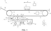
FIG. 1 is a schematic view showing a recording device and a transportation device. -
FIG. 2 is a schematic view showing the transportation device. -
FIG. 3 is a schematic view showing the transportation device. -
FIG. 4 is a schematic view showing the detector section. -
FIG. 5 is a flowchart showing the filter control process. -
FIG. 6 is a schematic view showing the transportation device. -
FIG. 7 is a schematic view showing the transportation device. - Hereinafter, an embodiment of a transportation device and a recording device will be described. In the following description, a direction intersecting the vertical direction Z is referred to as a width direction X, and a direction intersecting the vertical direction Z and the width direction X is referred to as a length direction Y. The upward direction in the vertical direction Z is referred to as an upward direction Z1, and the downward direction in the vertical direction Z is referred to as a downward direction Z2.
- As shown in
FIG. 1 , arecording device 11 may be an inkjet printer that performs recording on amedium 99 by ejecting ink, which is an example of liquid, onto themedium 99. Themedium 99 is fabric, but may be, for example, paper. - The
recording device 11 includes arecording section 12. Therecording section 12 is configured to perform recording on themedium 99 by ejecting liquid onto themedium 99. Therecording section 12 performs the recording on themedium 99, which is transported by a transportation belt 17 (described later). Therecording section 12 may be a head. Therecording section 12 may be a serial head or a line head. The serial head is the head that scans themedium 99 in the width direction X. The line head is the head that records all at once in the width direction X. - The
recording section 12 includes a plurality ofnozzles 13. Each of the plurality ofnozzles 13 is configured to open in the downward direction Z2. Each of the plurality ofnozzles 13 is configured to eject liquid. - The
recording device 11 includes atransportation device 14. Thetransportation device 14 is configured to transport themedium 99 in the transportation direction D. The transportation direction D may be along the length direction Y. Thetransportation device 14 may include afirst roller 15 and asecond roller 16. Thefirst roller 15 is located upstream of thesecond roller 16 in the transportation direction D. Thefirst roller 15 is located upstream of therecording section 12 in the transportation direction D. Thesecond roller 16 is located downstream of therecording section 12 in the transportation direction D. - The
transportation device 14 includes thetransportation belt 17. Thetransportation belt 17 is configured to transport themedium 99 in a state of supporting themedium 99. Thetransportation belt 17 is wound around a plurality of rollers. Thetransportation belt 17 is wound around thefirst roller 15 and thesecond roller 16. When thefirst roller 15 rotates, thetransportation belt 17 moves along thefirst roller 15 and thesecond roller 16. - The
transportation belt 17 includes asupport surface 18 that supports themedium 99. Thesupport surface 18 is an outer peripheral surface of thetransportation belt 17. Thetransportation belt 17 is, for example, a belt in which an adhesive is applied to thesupport surface 18. Themedium 99 is adhered to thesupport surface 18 by an adhesive. Thus, the posture of themedium 99 is stabilized. Themedium 99 may be adhered to thesupport surface 18 not only by the adhesive but also by, for example, an attraction force, an electrostatic force, an intermolecular force, or the like. In this way, thetransportation belt 17 transports themedium 99 supported on thesupport surface 18 by moving along thefirst roller 15 and thesecond roller 16. - The
transportation belt 17 may be soiled by transporting themedium 99. In particular, thesupport surface 18 tends to become dirty. For example, powder or fluff generated from themedium 99, dust in the air, a recording material from therecording section 12, or the like may adhere to thesupport surface 18. As a result, thesupport surface 18 is contaminated. When thesupport surface 18 is contaminated, there is a risk that the contamination may be attached to themedium 99. In addition, when thesupport surface 18 is contaminated, there is a risk that the adhesive force of thesupport surface 18 with respect to themedium 99 may be weakened. - The
transportation device 14 includes aroller drive section 19. Theroller drive section 19 is a driving source for rotating the plurality of rollers. Theroller drive section 19 may be a motor. Theroller drive section 19 is coupled to thefirst roller 15, but may be coupled to thesecond roller 16, or may be coupled to both thefirst roller 15 and thesecond roller 16. Theroller drive section 19 rotates thefirst roller 15. Theroller drive section 19 rotates thesecond roller 16 via thetransportation belt 17 with the rotation of thefirst roller 15. - The
transportation device 14 includes acleaning device 20. Thecleaning device 20 is configured to clean thetransportation belt 17. Specifically, thecleaning device 20 cleans thesupport surface 18 by contact with thesupport surface 18. Accordingly, the risk that dirt adheres to the medium 99 from thetransportation belt 17 is reduced. In addition, the risk of weakening the adhesive force of thesupport surface 18 is reduced. - The
cleaning device 20 is positioned to contact thesupport surface 18 in an area through which the medium 99 does not pass. The region through which the medium 99 does not pass may be a region facing a portion of thesupport surface 18 that moves in the direction opposite to the transportation direction D. That is, thecleaning device 20 may be positioned so as to sandwich therecording section 12 and thetransportation belt 17. Thecleaning device 20 cleans thesupport surface 18 after supporting the medium 99. Specifically, thecleaning device 20 cleans thesupport surface 18 after the medium 99 is peeled off. In other words, thecleaning device 20 cleans thesupport surface 18 before the medium 99 is supported again. - The
transportation device 14 may include aposition adjustment section 21. Thecleaning device 20 may include theposition adjustment section 21. Theposition adjustment section 21 moves thecleaning device 20 so as to adjust the distance between thesupport surface 18 and thecleaning device 20, but thetransportation belt 17 may be moved so as to adjust the distance between thesupport surface 18 and thecleaning device 20, or both may be moved. - The
transportation device 14 includes acontrol section 22. That is, therecording device 11 includes thecontrol section 22. Thetransportation device 14 may include another control section that controls thetransportation device 14, separately from thecontrol section 22 included in therecording device 11. - The
control section 22 controls therecording device 11. Thecontrol section 22 controls, for example, therecording section 12 and thetransportation device 14. Thecontrol section 22 controls various operations executed by therecording device 11. Thecontrol section 22 is configured as a circuit that includes - α: one or more processors that execute various processes in accordance with a computer program,
- β: one or more dedicated hardware circuits that execute at least some of the various processes, or
- γ: a combination thereof. The hardware circuit is, for example, an application specific integrated circuit. The processor includes a CPU and memory, such as RAM and ROM, which stores program code or instructions configured to cause the CPU to perform processing. The memory, that is, the computer-readable medium, includes any readable medium that can be accessed by a general purpose or special purpose computer.
- The configuration of the
cleaning device 20 will be described in detail with reference toFIG. 2 . - As shown in
FIG. 2 , thecleaning device 20 may include awashing section 23. That is, thetransportation device 14 may include thewashing section 23. Further, therecording device 11 may include thewashing section 23. Thewashing section 23 is configured to clean thetransportation belt 17 using cleaningfluid 98 contained in a reservoir tank 32 (described later). That is, the cleaningfluid 98 is a liquid for cleaning thetransportation belt 17. The cleaningfluid 98 is, for example, water, but may be another liquid. - The
washing section 23 may include a cleaningroller 24. The cleaningroller 24 cleans thesupport surface 18 by contact with thesupport surface 18. The cleaningroller 24 may be rotatably supported by asupport tank 31 to be described later. The cleaningroller 24 is located in the upward direction Z1 of thereservoir tank 32. The cleaningroller 24 can touch the cleaningfluid 98 contained in thereservoir tank 32. The cleaningroller 24 cleans thetransportation belt 17 using the cleaningfluid 98 contained in thereservoir tank 32. The cleaningfluid 98 flows down to thereservoir tank 32 after being used to clean thetransportation belt 17 in the cleaningroller 24. - The cleaning
roller 24 may be provided with afirst rotation shaft 25 and an absorbmember 26. Thefirst rotation shaft 25 is parallel to the shaft of thefirst roller 15 and the shaft of thesecond roller 16. The absorbmember 26 is a member capable of absorbing the cleaningfluid 98. The absorbmember 26 may be a sponge. The absorbmember 26 is supported by thefirst rotation shaft 25. The absorbmember 26 rotates together with thefirst rotation shaft 25. The absorbmember 26 cleans thesupport surface 18 by contact with thesupport surface 18. The cleaningroller 24 may be movable between a position at which the absorbmember 26 contacts thesupport surface 18 and a position at which the absorbmember 26 does not contact thesupport surface 18. - The
washing section 23 may be provided with abrush roller 27. Thebrush roller 27 cleans thesupport surface 18 by contacting thesupport surface 18. Thebrush roller 27 may be rotatably supported by the support tank 31 (described later). Thebrush roller 27 is located in the upward direction Z1 of thereservoir tank 32. Thebrush roller 27 can touch the cleaningfluid 98 contained in thereservoir tank 32. Thebrush roller 27 cleans thetransportation belt 17 using the cleaningfluid 98 contained in thereservoir tank 32. The cleaningfluid 98 flows down to thereservoir tank 32 after being used to clean thetransportation belt 17 in thebrush roller 27. That is, the cleaningfluid 98 is used to clean thetransportation belt 17 in thewashing section 23, and then flows down to thereservoir tank 32. - The
brush roller 27 may include asecond rotation shaft 28 and abrush 29. Thesecond rotation shaft 28 is parallel to thefirst rotation shaft 25. Thebrush 29 is supported by thesecond rotation shaft 28. Thebrush 29 extends radially from thesecond rotation shaft 28 when viewed from the axial direction of thesecond rotation shaft 28. Thebrush 29 rotates together with thesecond rotation shaft 28. Thebrush 29 cleans thesupport surface 18 by contact with thesupport surface 18. Thebrush roller 27 may be movable between a position where thebrush 29 contacts thesupport surface 18 and a position where thebrush 29 does not contact thesupport surface 18. - The
brush roller 27 may be provided at a position shifted from the cleaningroller 24 in the transportation direction D. Thebrush roller 27 comes into contact with a partial region of thesupport surface 18 before the cleaningroller 24 comes into contact with thesupport surface 18. - The
cleaning device 20 includes a cleaningfluid feeder 30. The cleaningfluid feeder 30 can contain the cleaningfluid 98. The cleaningfluid feeder 30 is configured to supply the contained cleaningfluid 98 to the cleaningroller 24 and thebrush roller 27. - The cleaning
fluid feeder 30 may include thesupport tank 31. The cleaningfluid feeder 30 includes thereservoir tank 32. That is, thetransportation device 14 includes thereservoir tank 32. Further, therecording device 11 includes thereservoir tank 32. - The cleaning
fluid feeder 30 may include asupply tank 33, afirst supply pipe 34, and asupply valve 35. The cleaningfluid feeder 30 may include afirst discharge pipe 36 and afirst discharge valve 37. The cleaningfluid feeder 30 may include asecond discharge pipe 38 and asecond discharge valve 39. - The cleaning
fluid feeder 30 may include arecirculation section 40. That is, thetransportation device 14 may include therecirculation section 40. Therecording device 11 may include therecirculation section 40. Therecirculation section 40 may include athird discharge pipe 41, afirst pump 42, arecirculation tank 43, asecond supply pipe 44, and asecond pump 45. - The
support tank 31 is configured to support the cleaningroller 24 and thebrush roller 27. Thesupport tank 31 includes abottom section 31A and aside section 31B. Thebottom section 31A constitutes the bottom surface of thesupport tank 31. Theside section 31B constitutes a side surface of thesupport tank 31. Thesupport tank 31 may house thereservoir tank 32. The cleaningroller 24 and thebrush roller 27 may be mounted on thesupport tank 31. Thesupport tank 31 can contain the cleaningfluid 98 overflowing from thereservoir tank 32. - The
support tank 31 includes a first outlet 50. The first outlet 50 is provided on thebottom section 31A, but may be provided on theside section 31B. The first outlet 50 is configured to communicate with thefirst discharge pipe 36. The first outlet 50 is an opening to discharge the cleaningfluid 98 that has overflowed from thereservoir tank 32 to thesupport tank 31 via thefirst discharge pipe 36. That is, the first outlet 50 can discharge the cleaningfluid 98 contained in thesupport tank 31. The discharge direction in which the cleaningfluid 98 is discharged from the first outlet 50 is a direction toward the downward direction Z2, but may be a direction toward the horizontal direction. - The
first discharge pipe 36 is a flow path for discharging the cleaningfluid 98 contained in thesupport tank 31 as waste liquid. Thefirst discharge pipe 36 may be a flow path for discharging the cleaningfluid 98 contained in thesupport tank 31 to a waste liquid tank (not shown) as waste liquid. Thefirst discharge valve 37 is provided in thefirst discharge pipe 36. Thefirst discharge valve 37 can open and close thefirst discharge pipe 36. When thefirst discharge valve 37 is opened, the discharge of the cleaningfluid 98 stored in thesupport tank 31 is started, and when thefirst discharge valve 37 is closed, the discharge of the cleaningfluid 98 stored in thesupport tank 31 is stopped. - The
reservoir tank 32 can contain the cleaningfluid 98. Thereservoir tank 32 includes abottom section 32A, afirst side section 32B, and a second side section 32C. Thebottom section 32A constitutes a bottom surface of thereservoir tank 32. Thefirst side section 32B constitutes a first side surface of thereservoir tank 32. The second side section 32C constitutes a second side surface of thereservoir tank 32. - The
reservoir tank 32 houses a part of the cleaningroller 24. Specifically, thereservoir tank 32 houses the bottom edge portion of the cleaningroller 24. Thereservoir tank 32 can supply the contained the cleaningfluid 98 to the cleaningroller 24. In this way, the cleaningfluid feeder 30 supplies the cleaningfluid 98 to the cleaningroller 24. - The
reservoir tank 32 houses a part of thebrush roller 27. Specifically, thereservoir tank 32 houses a bottom edge portion of thebrush roller 27. Thereservoir tank 32 can supply the contained the cleaningfluid 98 to thebrush roller 27. In this way, the cleaningfluid feeder 30 supplies the cleaningfluid 98 to thebrush roller 27. - The
reservoir tank 32 includes afirst inlet 51. Thefirst inlet 51 is provided in thefirst side section 32B, but may be provided in the second side section 32C. Thereservoir tank 32 may include asecond outlet 52. Thesecond outlet 52 is provided in thebottom section 32A, but may be provided in thefirst side section 32B or the second side section 32C. Thereservoir tank 32 may include athird outlet 53. Thethird outlet 53 is provided in thebottom section 32A, but may be provided in thefirst side section 32B or the second side section 32C. Thereservoir tank 32 may be provided with asecond inlet 54. Thesecond inlet 54 is provided in the second side section 32C, but may be provided in thefirst side section 32B. - The
first inlet 51 is configured so as to communicate with thefirst supply pipe 34. Thefirst inlet 51 is an opening for supplying the cleaningfluid 98 from thesupply tank 33 to thereservoir tank 32. - The
supply tank 33 can contain the cleaningfluid 98 to be supplied to thereservoir tank 32. Thefirst supply pipe 34 is configured to communicate thesupply tank 33 with thereservoir tank 32. Thefirst supply pipe 34 is a flow path for supplying the cleaningfluid 98 from thesupply tank 33 to thereservoir tank 32. Thesupply valve 35 is provided in thefirst supply pipe 34. Thesupply valve 35 can open and close thefirst supply pipe 34. When thesupply valve 35 is opened, the supply of the cleaningfluid 98 to thereservoir tank 32 is started, and when thesupply valve 35 is closed, the supply of the cleaningfluid 98 to thereservoir tank 32 is stopped. - The
second outlet 52 is configured to communicate with thesecond discharge pipe 38. Thesecond outlet 52 is an opening for discharging the cleaningfluid 98 stored in thereservoir tank 32 through thesecond discharge pipe 38. That is, thesecond outlet 52 can discharge the cleaningfluid 98 contained in thereservoir tank 32. The discharge direction in which the cleaningfluid 98 is discharged from thesecond outlet 52 is a direction toward the downward direction Z2, but may be a direction toward the horizontal direction. - The
second discharge pipe 38 is configured to communicate with thereservoir tank 32. Thesecond discharge pipe 38 may be a flow path for discharging the cleaningfluid 98 contained in thereservoir tank 32 as waste liquid. Thesecond discharge pipe 38 may be a flow path for discharging the cleaningfluid 98 contained in thereservoir tank 32 to a waste liquid tank (not shown) as a waste liquid. Thesecond discharge valve 39 is provided in thesecond discharge pipe 38. Thesecond discharge valve 39 can open and close thesecond discharge pipe 38. When thesecond discharge valve 39 is opened, the discharge of the cleaningfluid 98 stored in thereservoir tank 32 is started, and when thesecond discharge valve 39 is closed, the discharge of the cleaningfluid 98 stored in thereservoir tank 32 is stopped. - The
third outlet 53 is configured to communicate with therecirculation section 40. That is, thethird outlet 53 can discharge the cleaningfluid 98 to therecirculation section 40. Thethird outlet 53 is configured to communicate with thethird discharge pipe 41. Thethird outlet 53 is an opening for liquid collection of the cleaningfluid 98 stored in thereservoir tank 32 to therecirculation tank 43 through thethird discharge pipe 41. That is, thethird outlet 53 can discharge the cleaningfluid 98 contained in thereservoir tank 32. The discharge direction in which the cleaningfluid 98 is discharged from thethird outlet 53 is a direction toward the downward direction Z2, but may be a direction toward the horizontal direction. Thethird outlet 53 corresponds to an example of a discharge port. - The
recirculation section 40 is configured to circulate the cleaningfluid 98 contained in thereservoir tank 32. Therecirculation section 40 resupplies the cleaningfluid 98 contained in thereservoir tank 32 to thereservoir tank 32. - The
third discharge pipe 41 is a flow path for collecting the cleaningfluid 98 accommodated in thereservoir tank 32 to therecirculation tank 43. Thefirst pump 42 is provided in thethird discharge pipe 41. Thefirst pump 42 is a pump for collecting the cleaningfluid 98 contained in thereservoir tank 32 to therecirculation tank 43 via thethird discharge pipe 41. - The
recirculation tank 43 can contain the cleaningfluid 98 collected from thereservoir tank 32 via thethird discharge pipe 41. In therecirculation tank 43, a coagulant may be added to the collected the cleaningfluid 98. The coagulant is an agent used for promoting sedimentation by aggregating particles dispersed in the cleaning fluid. - The
second inlet 54 is configured to communicate with therecirculation section 40. Thesecond inlet 54 is configured to communicate with thesecond supply pipe 44. Thesecond inlet 54 is an opening for supplying the cleaningfluid 98 from therecirculation tank 43 to thereservoir tank 32 via thesecond supply pipe 44. - The
second supply pipe 44 is configured to communicate with therecirculation tank 43 and thereservoir tank 32. Thesecond supply pipe 44 is a flow path for supplying the cleaningfluid 98 from therecirculation tank 43 to thereservoir tank 32. Thesecond pump 45 is provided in thesecond supply pipe 44. Thesecond pump 45 is a pump for supplying the cleaningfluid 98 from therecirculation tank 43 to thereservoir tank 32 through thesecond supply pipe 44. - The cleaning
fluid feeder 30 may be provided with a liquid level detector section (not shown). The liquid level detector section is provided in thereservoir tank 32. The liquid level detector section can detect the liquid level height of the cleaningfluid 98 contained in thereservoir tank 32. Thecontrol section 22 may control the liquid level height of the cleaningfluid 98 contained in thereservoir tank 32 to be a reference height by controlling the open and closed of thesupply valve 35 based on the detection signal from the liquid level detector section. - The cleaning
fluid feeder 30 may be provided with a squeezing member (not illustrated). The squeezing member is configured to squeezing the cleaningfluid 98 from the absorbmember 26. Thecleaning device 20 may include a blowing section (not illustrated). The blowing section may be configured to blow a gas to thesupport surface 18 cleaned by thewashing section 23. The blowing section may be configured to blow a gas to the absorbmember 26. - As shown in
FIG. 3 , the cleaningfluid feeder 30 includes afilter section 60. Thefilter section 60 is configured to collect theforeign matter 97 contained in the cleaningfluid 98 contained in thereservoir tank 32. Theforeign matter 97 is a collectable substance contained in the cleaningfluid 98, and may contain suspended matter or deposits. The suspended matter may be a substance suspended in the cleaningfluid 98. The deposits may be a substance that is deposited in the cleaningfluid 98. In particular, thefilter section 60 is configured to collect theforeign matter 97 contained in the cleaningfluid 98 at thethird outlet 53. - The
filter section 60 includes afilter 61 and afilter moving section 62. That is, thetransportation device 14 includes thefilter 61 and thefilter moving section 62. Further, therecording device 11 includes thefilter 61 and thefilter moving section 62. - The
filter 61 is provided at a position covering thethird outlet 53. Thefilter 61 is provided at a position to cover thethird outlet 53 from the inside of thereservoir tank 32. Thefilter 61 is configured to collect theforeign matter 97 contained in the cleaningfluid 98 stored in thereservoir tank 32. - The
filter 61 may have an elongated shape or may have an endless shape. Thefilter 61 has an endless shape in the vertical direction Z and the width direction X, but may have an endless shape in the vertical direction Z and the length direction Y. A part of the region of thefilter 61 is contained in thereservoir tank 32, but the remaining region is not contained in thereservoir tank 32 and is positioned outside thereservoir tank 32. Some areas of thefilter 61 touches the cleaningfluid 98, while the remaining areas does not touch the cleaningfluid 98. - The
filter 61 is configured to be movable. The movement path of thefilter 61 may be a path along the outer peripheral surface and the inner peripheral surface of thereservoir tank 32. The movement path of thefilter 61 includes a position where the predetermined region touches the cleaningfluid 98 and a position where the predetermined region does not touch the cleaningfluid 98. That is, thefilter 61 is movable between a position where the predetermined region touches the cleaningfluid 98 and a position where the predetermined region does not touch the cleaningfluid 98. - The movement path of the
filter 61 includes a position at which the predetermined region covers thethird outlet 53 and a position at which the predetermined region does not cover thethird outlet 53. That is, thefilter 61 is movable between a position where the predetermined region covers thethird outlet 53 and a position where the predetermined region does not cover thethird outlet 53. In particular, thefilter 61 is movable in a state where any region thereof covers thethird outlet 53. In other words, thefilter 61 is movable while covering thethird outlet 53. - In this manner, the
filter 61 is movable so that the position of thefilter 61 changes from a position where the predetermined region covers thethird outlet 53 to a position where the predetermined region does not cover thethird outlet 53. Thefilter 61 is movable so that the position of thefilter 61 changes from a position where the predetermined region does not cover thethird outlet 53 to a position where the predetermined region covers thethird outlet 53. That is, thefilter 61 is movable so as to change the positional relationship between the predetermined region and thethird outlet 53. - The
filter moving section 62 can move thefilter 61. Thefilter moving section 62 can move thefilter 61 in the horizontal direction in the vicinity of thethird outlet 53. That is, thefilter moving section 62 can move thefilter 61 in a direction intersecting the discharge direction in which the cleaningfluid 98 is discharged from thethird outlet 53 in the vicinity of thethird outlet 53. - In particular, the
filter moving section 62 can move thefilter 61 in a state of covering thethird outlet 53. Thefilter moving section 62 can move thefilter 61 so that a predetermined region of thefilter 61 changes from a position covering thethird outlet 53 to a position not covering thethird outlet 53. Thefilter moving section 62 can move thefilter 61 so that a predetermined region of thefilter 61 changes from a position where the predetermined region does not cover thethird outlet 53 to a position where the predetermined region covers thethird outlet 53. That is, thefilter moving section 62 can move thefilter 61 so as to change the positional relationship between the predetermined region of thefilter 61 and thethird outlet 53. - The
filter moving section 62 may include a plurality ofrollers 63 and adrive section 64. The plurality ofrollers 63 are arranged along the movement path of thefilter 61. The plurality ofrollers 63 move thefilter 61 by coming into contact with thefilter 61. Thedrive section 64 is a driving source that rotates at least one of the plurality ofrollers 63. Thedrive section 64 may be a motor. - The
filter section 60 may include aremoval section 65. That is, thetransportation device 14 may include theremoval section 65. Further, therecording device 11 may include theremoval section 65. Theremoval section 65 is configured to remove theforeign matter 97 collected by thefilter 61 from thefilter 61. - The
removal section 65 is arranged along the movement path of thefilter 61. Theremoval section 65 is provided outside thereservoir tank 32. Theremoval section 65 can contact the outer circumferential surface of thefilter 61. Theremoval section 65 may have a plate shape. Theremoval section 65 may be provided so as to be inclined in a direction opposite to the movement direction of thefilter 61. - The
filter section 60 may includes areceiver section 66. That is, thetransportation device 14 may include thereceiver section 66. In addition, therecording device 11 may include thereceiver section 66. Thereceiver section 66 is configured to receive theforeign matter 97 removed by theremoval section 65. Thereceiver section 66 is provided outside thereservoir tank 32. Thereceiver section 66 may be located below theremoval section 65 in downward direction Z2. Thereceiver section 66 may be configured to open toward the upward direction Z1. - As shown in
FIG. 4 , thefilter section 60 may include adetector section 67. That is, thetransportation device 14 may include thedetector section 67. Further, therecording device 11 may include thedetector section 67. Thedetector section 67 detects theforeign matter 97 collected by thefilter 61. - The
detector section 67 may be an optical sensor. Thedetector section 67 may include alight projection section 67A and alight receiver section 67B. Thelight projection section 67A may be provided in thereservoir tank 32. Thelight receiver section 67B may be provided in thethird discharge pipe 41. Thelight receiver section 67B is provided such that thethird outlet 53 is located between thelight receiver section 67B and thelight projection section 67A. Thelight receiver section 67B is provided such that thefilter 61 covering thethird outlet 53 is positioned between thelight projection section 67A and thelight receiver section 67B. As described above, thelight receiver section 67B may detect theforeign matter 97 when the light projected from thelight projection section 67A is blocked by theforeign matter 97 collected by thefilter 61. - Here, the filter control process will be described with reference to
FIG. 5 . The filter control process is a process executed by thecontrol section 22 at predetermined intervals. - As shown in
FIG. 5 , in Step S10, thecontrol section 22 executes the collection amount detection processing. In this processing, thecontrol section 22 detects the collection amount of theforeign matter 97 at the position of thefilter 61 covering thethird outlet 53 based on the detection signal from thedetector section 67. When step S10 ends, thecontrol section 22 changes the processing to step S11. - In step S11, the
control section 22 determines whether or not the collection amount has exceeded a threshold value. The threshold value may correspond to a collection amount suitable for the movement of thefilter 61. That is, the threshold value may correspond to a collection amount suitable for the movement of thefilter 61. The threshold value may correspond to the collection amount when the detection signal is received from thedetector section 67. When thecontrol section 22 determines that the collection amount does not exceed the threshold value, it shifts the processing to step S13 without executing step S12. When thecontrol section 22 determines that the collection amount exceeds the threshold value, it shifts the processing to step S12. - In step S12, the
control section 22 executes a filter moving process. In this process, thecontrol section 22 controls thefilter moving section 62 so as to move thefilter 61 by a predetermined distance along the moving path. In particular, thecontrol section 22 moves thefilter 61 from a position where a predetermined region of thefilter 61 covers thethird outlet 53 to a position where the predetermined region of thefilter 61 does not cover thethird outlet 53. Thecontrol section 22 moves thefilter 61 from a position where a predetermined region of thefilter 61 covers thethird outlet 53 to a position where the predetermined region of thefilter 61 does not touch the cleaningfluid 98. In this manner, the movement condition of thefilter 61 may include the detection result detected by thedetector section 67. That is, when it is determined that the collection amount exceeds the threshold value based on the detection result detected by thedetector section 67, thecontrol section 22 causes thefilter moving section 62 to move thefilter 61. When step S12 is completed, thecontrol section 22 shifts the processing to step S13. - In step S13, the
control section 22 determines whether or not the predetermined time has elapsed. In this process, thecontrol section 22 determines that the predetermined time has elapsed when a predetermined date and time is reached. In a case where thecontrol section 22 determines that the predetermined time has not elapsed, thecontrol section 22 ends the filter control process without executing step S14. When thecontrol section 22 determines that the predetermined time has elapsed, it shifts the process to step S14. - In step S14, the
control section 22 executes the filter moving process as in step S12. As described above, the movement condition of thefilter 61 may include a predetermined date and time. That is, thecontrol section 22 causes thefilter moving section 62 to move thefilter 61 when a predetermined date and time is reached. When step S14 is completed, thecontrol section 22 ends the filter control processing. - In this way, the
control section 22 controls thefilter moving section 62. In particular, thecontrol section 22 causes thefilter moving section 62 to move thefilter 61 based on the detection result detected by thedetector section 67. In addition, thecontrol section 22 causes thefilter moving section 62 to move thefilter 61 when a predetermined time has elapsed. - The operation of the first embodiment will be described.
- As shown in
FIG. 3 , thefilter 61 covers thethird outlet 53 in thereservoir tank 32. Thus, thefilter 61 can collect theforeign matter 97 contained in the cleaningfluid 98 stored in thereservoir tank 32 without discharging theforeign matter 97 to thethird discharge pipe 41 via thethird outlet 53. - When the movement condition of the
filter 61 is satisfied, it moves by a predetermined distance along the movement path. As a result, the predetermined region of thefilter 61 covering thethird outlet 53 moves to a position outside thereservoir tank 32 where the predetermined region does not cover thethird outlet 53 and does not touch the cleaningfluid 98. On the other hand, a partial region of thefilter 61 that does not cover thethird outlet 53 moves to a position that covers thethird outlet 53. - Thereafter, as shown in
FIG. 6 , while thefilter 61 is moving, theforeign matter 97 collected by thefilter 61 is removed by theremoval section 65 outside thereservoir tank 32. Then, theforeign matter 97 removed from thefilter 61 by theremoval section 65 is received in thereceiver section 66 outside thereservoir tank 32. As a result, theforeign matter 97 received by thereceiver section 66 can be discarded without being mixed with the cleaningfluid 98. - Effects of the first embodiment will be described.
- (1-1) It is possible to move the
filter 61 so that the positional relationship between the predetermined region of thefilter 61 and thethird outlet 53 changes. Thus, the region where theforeign matter 97 is collected by thefilter 61 can be moved with respect to thethird outlet 53. Therefore, it is possible to suppress the clogging of thethird outlet 53 due to theforeign matter 97 contained in the cleaningfluid 98. - (1-2) The
transportation device 14 includes theremoval section 65 that removes theforeign matter 97 collected by thefilter 61. According to this configuration, theforeign matter 97 collected by thefilter 61 can be removed from thefilter 61 by theremoval section 65. Accordingly, even when thefilter 61 is reused, theforeign matter 97 can be appropriately collected by thefilter 61. Accordingly, it is possible to increase the degree of contribution to the environment while reducing the frequency of replacement of thefilter 61. Therefore, it is possible to suppress the clogging of thethird outlet 53 due to theforeign matter 97 contained in the cleaningfluid 98, and it is possible to improve convenience for the user. - (1-3) The
transportation device 14 includes thereceiver section 66 for receiving theforeign matter 97 removed by theremoval section 65. According to this configuration, theforeign matter 97 removed from thefilter 61 can be received in thereceiver section 66. Accordingly, it is possible to improve the certainty of receiving theforeign matter 97 removed from thefilter 61 and to easily discard theforeign matter 97 removed from thefilter 61. Therefore, it is possible to suppress the clogging of thethird outlet 53 due to theforeign matter 97 contained in the cleaningfluid 98, and it is possible to improve convenience for the user. - (1-4) The
filter 61 is movable while covering thethird outlet 53. According to this configuration, even in a case where thefilter 61 is moved such that the positional relationship between the predetermined region of thefilter 61 and thethird outlet 53 changes, thethird outlet 53 is covered by thefilter 61. Accordingly, it is possible to suppress theforeign matter 97 from flowing out from thethird outlet 53 while maintaining a state in which the cleaningfluid 98 can be discharged from thethird outlet 53. Therefore, it is possible to suppress the clogging of thethird outlet 53 due to theforeign matter 97 contained in the cleaningfluid 98, and it is possible to improve convenience for the user. - (1-5) The
control section 22 causes thefilter moving section 62 to move thefilter 61 based on the detection result detected by thedetector section 67. According to this configuration, it is possible to move thefilter 61 on the basis of the detection result of theforeign matter 97 collected by thefilter 61. Accordingly, it is possible to move thefilter 61 in consideration of the detection result. Therefore, it is possible to suppress the clogging of thethird outlet 53 due to theforeign matter 97 contained in the cleaningfluid 98. - (1-6) The
control section 22 causes thefilter moving section 62 to move thefilter 61 when a predetermined time has elapsed. According to this configuration, it is possible to move thefilter 61 when the predetermined time elapses. Accordingly, it is possible to move thefilter 61 in consideration of the elapse of time. Therefore, it is possible to suppress the clogging of thethird outlet 53 due to theforeign matter 97 contained in the cleaningfluid 98. - (1-7) The
filter moving section 62 can move thefilter 61 such that the predetermined region of thefilter 61 changes from a position covering thethird outlet 53 to a position not covering thethird outlet 53. According to this configuration, even in a case where theforeign matter 97 is collected in the predetermined region of thefilter 61 that covers thethird outlet 53, it is possible to move thefilter 61 such that the predetermined region changes to a position that does not cover thethird outlet 53. For this reason, it is possible to increase the certainty of collecting theforeign matter 97 by thefilter 61. Therefore, it is possible to suppress the clogging of thethird outlet 53 due to theforeign matter 97 contained in the cleaningfluid 98. - (1-8) The
third outlet 53 discharges the cleaningfluid 98 to therecirculation section 40 that circulates the cleaningfluid 98 stored in thereservoir tank 32. According to this configuration, even when the cleaningfluid 98 stored in thereservoir tank 32 is circulated, theforeign matter 97 can be collected from the cleaningfluid 98 circulated by thefilter 61. Thus, it is possible to suppress theforeign matter 97 from being contained in the circulated cleaningfluid 98. Therefore, it is possible to suppress the clogging of thethird outlet 53 due to theforeign matter 97 contained in the cleaningfluid 98, and it is possible to improve convenience for the user.
The discharge frequency of the cleaningfluid 98 from thethird outlet 53 tends to be higher than the discharge frequency of the cleaningfluid 98 from the first outlet 50, and tends to be higher than the discharge frequency of the cleaningfluid 98 from thesecond outlet 52. For this reason, it is possible to suppress the clogging of thethird outlet 53 due to theforeign matter 97 included in the cleaningfluid 98 by moving thefilter 61 which covers thethird outlet 53 in which the discharge frequency of the cleaningfluid 98 is high. - (1-9) The
third outlet 53 is provided in thebottom section 32A of thereservoir tank 32. Therefore, thefilter 61 can collect not only the floating matter in thereservoir tank 32 but also the deposited matter in thereservoir tank 32. Therefore, it is possible to suppress the clogging of thethird outlet 53 due to theforeign matter 97 contained in the cleaningfluid 98. - Next, a second embodiment will be described. In the second embodiment, the filter may be moved by rotation of the filter. The
third outlet 53 may extend in a direction intersecting the vertical direction Z. In the following description, the same components as those of the above-described embodiment will be denoted by the same reference numerals and overlapping description thereof will be omitted or simplified, and components different from those of the above-described embodiment will be mainly described. - As shown in
FIG. 7 , thethird outlet 53 is provided in a side section of thereservoir tank 32. It is configured to open in the horizontal direction. Thethird outlet 53 is configured to open in the horizontal direction. Thethird outlet 53 is positioned in a downward direction Z2 than the height of the liquid level of the cleaningfluid 98. Thethird discharge pipe 41 extends in the horizontal direction. That is, the discharge direction of the cleaningfluid 98 discharged from thethird outlet 53 is the horizontal direction. - The cleaning
fluid feeder 30 includes afilter section 70. Thefilter section 70 includes afilter 71 and afilter moving section 72. Thefilter 71 may be circular. Thefilter 71 is provided such that atop end 71A is higher than the liquid level of the cleaningfluid 98 stored in thereservoir tank 32 and abottom edge 71B is lower than the liquid level of the cleaningfluid 98 stored in thereservoir tank 32 in the vertical direction Z. Thefilter 71 is configured to be movable by rotation. Thefilter 71 is movable in the state of covering thethird outlet 53. - In this way, the
filter 71 is movable so that the predetermined region changes from the position covering thethird outlet 53 to the position not covering thethird outlet 53. Thefilter 71 is movable from a position where the predetermined region does not cover thethird outlet 53 to a position where the predetermined region covers thethird outlet 53. That is, thefilter 71 is movable so as to change the positional relationship between the predetermined region and thethird outlet 53. - The
filter moving section 72 may include afilter rotation shaft 73 and adrive section 74. Thefilter rotation shaft 73 extends in the horizontal direction. Thefilter rotation shaft 73 extends along a direction in which thethird outlet 53 opens. Thefilter 71 is rotatably attached to thefilter rotation shaft 73. - The
drive section 74 rotates thefilter rotation shaft 73. Therefore, when thefilter rotation shaft 73 is rotated by thedrive section 74, thefilter 71 is rotated together with thefilter rotation shaft 73. That is, thefilter 71 is rotatable about an axis that is a rotation shaft along the discharge direction in which the cleaningfluid 98 is discharged from thethird outlet 53. - In this manner, the
filter moving section 72 can move thefilter 71. Thefilter moving section 72 can move thefilter 71 so that a predetermined region of thefilter 71 changes from a position covering thethird outlet 53 to a position not covering thethird outlet 53. That is, thefilter moving section 72 can move thefilter 71 so as to change the positional relationship between the predetermined region of thefilter 71 and thethird outlet 53. - The
filter section 70 may be provided with aremoval section 75. Theremoval section 75 is provided at a position higher than the liquid level of the cleaningfluid 98 stored in thereservoir tank 32. Theremoval section 75 may or may not be housed in thereservoir tank 32. Theremoval section 75 is provided along thefilter 71. Theremoval section 75 may be provided so as to be inclined in a direction opposite to the rotation direction of thefilter 71. - The
filter section 70 may includes areceiver section 76. Thereceiver section 76 is provided at a position higher than the liquid level of the cleaningfluid 98 stored in thereservoir tank 32. Thereceiver section 76 may or may not be housed in thereservoir tank 32. - Effects of the second embodiment will be described.
- (2-1) The
filter 71 is rotatable about the rotation shaft that is an axis along the discharge direction in which the cleaningfluid 98 is discharged from thethird outlet 53. According to this configuration, thefilter 71 can be moved by a simple configuration, and the clogging of thethird outlet 53 due to theforeign matter 97 contained in the cleaningfluid 98 can be suppressed. - (2-2) The discharge direction in which the cleaning
fluid 98 is discharged from thethird outlet 53 is a direction intersecting the vertical direction Z. Thefilter 71 is rotatable about the rotation shaft that is an axis along the discharge direction in which the cleaningfluid 98 is discharged from thethird outlet 53. Thefilter 71 is provided such that thetop end 71A is higher than the liquid level of the cleaningfluid 98 stored in thereservoir tank 32 and thebottom edge 71B is lower than the liquid level of the cleaningfluid 98 stored in thereservoir tank 32 in the vertical direction Z. According to this configuration, it is possible to remove theforeign matter 97 collected by thefilter 71 at a position higher than the liquid level of the cleaningfluid 98 stored in thereservoir tank 32. Thus, it is possible to prevent theforeign matter 97 removed from thefilter 71 from touching with the cleaningfluid 98 stored in thereservoir tank 32. Therefore, it is possible to increase the certainty of removing theforeign matter 97 collected by thefilter 71. Therefore, it is possible to suppress the clogging of thethird outlet 53 due to theforeign matter 97 contained in the cleaningfluid 98, and it is possible to improve convenience for the user. - The present embodiment can be modified as follows. The present embodiment and the following modifications can be implemented in combination with each other within a range that is not technically contradictory.
- In the first embodiment, for example, the discharge direction of the cleaning
fluid 98 discharged from thethird outlet 53 may be a horizontal direction. Also in this case, thefilter 61 is provided so as to cover thethird outlet 53. - In the second embodiment, for example, the discharge direction of the cleaning
fluid 98 discharged from thethird outlet 53 may be the vertical direction Z, and thefilter section 70 may be configured such that thefilter 71 rotates about the rotation shaft that is an axis along the discharge direction. That is, thefilter 71 may be rotatable about the rotation shaft that is an axis along the vertical direction Z. - The
filters third outlet 53. In other words, there may be a period in which thethird outlet 53 are covered by thefilters third outlet 53 are not covered by thefilters - The
filters third outlet 53 or may cover a part of the region of thethird outlet 53. In other words, thethird outlet 53 may be partially or entirely covered by thefilters - Although the
filters third outlet 53 to the position where the predetermined area does not cover thethird outlet 53, the predetermined area may be moved from the position where the predetermined area covers the entire area of thethird outlet 53 to the position where the predetermined area covers a part of the area of thethird outlet 53. That is, the positional relationship between the predetermined region of thefilter third outlet 53 may be changed. - The
third outlet 53 is an example of the discharge port, but is not limited thereto. The first outlet 50 may be an example of a discharge port. Thesecond outlet 52 may be an example of the discharge port. At least one of the first outlet 50, thesecond outlet 52, and thethird outlet 53 may be an example of the discharge port. In such a case, thefilters second outlet 52 and thethird outlet 53, or the filters may be provided so as to cover thesecond outlet 52 and thethird outlet 53, respectively. - The
support tank 31 is configured not to be included in thereservoir tank 32, but may be configured to be included in thereservoir tank 32. In such a case, thereservoir tank 32 may correspond to the first reservoir tank, and thesupport tank 31 may correspond to the second reservoir tank. Thesupport tank 31 and thereservoir tank 32 may be integrally provided. - The
detector section 67 outputs the detection signal to thecontrol section 22 when the collection amount of theforeign matter 97 collected in thefilters detector section 67 may output a detection signal corresponding to the collection amount of theforeign matter 97 collected in thefilters control section 22. In this case, thecontrol section 22 may specify the collection amount of theforeign matter 97 corresponding to the detection signal based on the detection signal from thedetector section 67, and determine whether or not the collection amount of theforeign matter 97 exceeds a threshold value. - The
detector section 67 may be, for example, an imaging capture section that captures images. In this case, thecontrol section 22 may analyze the image data captured by thedetector section 67 and detect the collection amount of theforeign matter 97 collected by thefilters - The
detector section 67 may be, for example, a pressure sensor. Thedetector section 67 may be provided in thethird discharge pipe 41. When the fluid pressure of the cleaningfluid 98 flowing through thethird discharge pipe 41 becomes higher than the reference fluid pressure, thecontrol section 22 may determine that the collection amount of theforeign matter 97 collected by thefilters - The
control section 22 may compare the collection amount of theforeign matter 97 collected by thefilters control section 22 may move thefilters foreign matter 97 collected in thefilters foreign matter 97 exceeds a second threshold value larger than the first threshold value. - The
control section 22 may store a determination date and time when it is determined that the collection amount of theforeign matter 97 collected in thefilters foreign matter 97 exceeds the threshold value before a predetermined time elapses from the previous determination date and time. - The
control section 22 may store the date and time of the previous movement of thefilters filters control section 22 may cause thefilter moving sections filters - The cleaning
fluid feeder 30 may be configured to supply the cleaningfluid 98 to the cleaningroller 24 and thebrush roller 27 by spraying or dropping the cleaningfluid 98 toward the cleaningroller 24 and thebrush roller 27. - The liquid ejected by the
recording section 12 is not limited to ink, and may be, for example, a liquid material in which particles of a functional material are dispersed or mixed in a liquid. For example, therecording section 12 may eject a liquid body containing a material such as an electrode material or a pixel material used for manufacturing a liquid crystal display, an electroluminescence display, a surface emitting display, or the like in a dispersed or dissolved form. - As used herein, the phrase "at least one of" means one or more of the desired options. As an example, the phrase "at least one of" as used herein means only one option if the number of options is two, or both of the two options. As another example, the expression "at least any" as used herein means only one option or a combination of any two or more options when the number of options is three or more.
- Hereinafter, technical ideas grasped from the above-described embodiment and modifications, and operations and effects thereof, will be described. The present technical idea and the operations and effects thereof can be combined with each other within a technically consistent range.
- (A) A transportation device includes a transportation belt configured to transport the medium in a state of supporting the medium, a reservoir tank that is configured to contain a cleaning fluid for cleaning the transportation belt and that has a discharge port through which the contained cleaning fluid is dischargeable, a filter that is provided at a position covering the discharge port and that collects foreign matter included in the cleaning fluid contained in the reservoir tank, and a filter moving section configured to move the filter, wherein the filter moving section is configured to move the filter such that a positional relationship between a predetermined region of the filter and the discharge port changes.
According to this configuration, it is possible to move the filter so that the positional relationship between the predetermined region of the filter and the discharge port changes. With this configuration, it is possible to move the region where the foreign matter is collected by the filter with respect to the discharge port. Therefore, it is possible to suppress clogging of the discharge port due to foreign matter contained in the cleaning fluid. - (B) The above-described transportation device may further include a removal section configured to remove the foreign matter collected by the filter.
According to this configuration, it is possible to remove the foreign matter collected by the filter from the filter. With this configuration, even when the filter is reused, the foreign matter can be appropriately collected by the filter. Therefore, the clogging of the discharge port due to foreign matter contained in the cleaning fluid can be suppressed, and the contribution to the environment can be improved. - (C) The above-described transportation device may include a receiver section configured to receive the foreign matter removed by the removal section.
According to this configuration, it is possible to receive the foreign matter removed from the filter. Thus, it is possible to improve the reliability of receiving the foreign matter removed from the filter, and to easily discard the foreign matter removed from the filter. Therefore, it is possible to suppress the clogging of the discharge port due to foreign matter contained in the cleaning fluid, and it is possible to improve convenience for the user. - (D) In the above-described transportation device, the filter may be rotatable around an axis, as a rotation shaft, along a discharge direction in which the cleaning fluid is discharged from the discharge port.
According to this configuration, the filter can be moved by a simple configuration, and the clogging of the discharge port due to foreign matter contained in the cleaning fluid can be suppressed. - (E) In the above-described transportation device, the filter is rotatable around an axis, as a rotation shaft, along a discharge direction in which the cleaning fluid is discharged from the discharge port, the discharge direction is a direction intersecting a vertical direction, the filter is provided such that, in the vertical direction, the top end is higher than the liquid level of the cleaning fluid contained in the reservoir tank and the bottom edge is lower than the liquid level of the cleaning fluid contained in the reservoir tank, and the removal section may be provided at a position higher than a liquid level of the cleaning fluid stored in the reservoir tank.
According to this configuration, the filter can be moved with a simple configuration. The foreign matter collected by the filter at a position higher than the liquid level of the cleaning fluid contained in the reservoir tank can be removed. Thus, it is possible to suppress that the foreign matter removed from the filter touches the cleaning fluid contained in the reservoir tank. Therefore, it is possible to increase the certainty of removing the foreign matter collected by the filter. Therefore, it is possible to suppress the clogging of the discharge port due to foreign matter contained in the cleaning fluid, and it is possible to improve convenience for the user. - (F) In the above-described transportation device, the filter may be movable in a state of covering the discharge port.
According to this configuration, even in a case where the filter is moved such that the positional relationship between the predetermined region of the filter and the discharge port changes, the discharge port is covered by the filter. Accordingly, it is possible to suppress the foreign matter from flowing out from the discharge port while maintaining a state in which the cleaning fluid can be discharged from the discharge port. Therefore, it is possible to suppress the clogging of the discharge port due to foreign matter contained in the cleaning fluid, and it is possible to improve convenience for the user. - (G) The above-described transportation device may further include a detector section for detecting foreign matter collected by the filter and a control section configured to control the filter moving section, wherein the control section may cause the filter moving section to move the filter, based on a detection result detected by the detector section.
According to this configuration, it is possible to move the filter on the basis of the detection result of detecting the foreign matter collected by the filter. Accordingly, it is possible to move the filter in consideration of the detection result. Therefore, it is possible to suppress clogging of the discharge port due to foreign matter contained in the cleaning fluid. - (H) The above-described transportation device may further include a control section configured to control the filter moving section, wherein the control section may cause the filter moving section to move the filter when a predetermined time has elapsed.
According to this configuration, it is possible to move the filter when the predetermined time elapses. It is possible to move the filter taking into account the passage of time. Therefore, it is possible to suppress clogging of the discharge port due to foreign matter contained in the cleaning fluid. - (I) In the above-described transportation device, the filter moving section may be configured to move the filter so that a predetermined region of the filter changes from a position covering the discharge port to a position uncovering the discharge port.
According to this configuration, even when foreign matter is collected in a predetermined region of the filter covering the discharge port, the filter can be moved so that the predetermined region changes to a position where the filter does not cover the discharge port. Therefore, it is possible to increase the certainty of collecting the foreign matter by the filter. Therefore, it is possible to suppress clogging of the discharge port due to foreign matter contained in the cleaning fluid. - (J) The above-described transportation device includes a recirculation section configured to circulate the cleaning fluid in the reservoir tank, wherein the discharge port may discharge the cleaning fluid to the recirculation section.
According to this configuration, even when the cleaning fluid contained in the reservoir tank is circulated, the foreign matter can be collected from the circulating cleaning fluid by the filter. As a result, it is possible to suppress foreign matter from being contained in the circulating cleaning fluid. Therefore, it is possible to suppress the clogging of the discharge port due to foreign matter contained in the cleaning fluid, and it is possible to improve convenience for the user. - (K) A recording device includes a transportation belt configured to transport the medium in a state of supporting the medium, a recording section that performs recording by ejecting a liquid onto a medium transported by the transportation belt, a reservoir tank that is configured to contain a cleaning fluid for cleaning the transportation belt and that has a discharge port through which the contained cleaning fluid is dischargeable, a filter that is provided at a position covering the discharge port and that collects foreign matter included in the cleaning fluid contained in the reservoir tank, and a filter moving section configured to move the filter, wherein the filter moving section is configured to move the filter such that a positional relationship between a predetermined region of the filter and the discharge port changes. According to this configuration, the same effect as in (A) can be obtained.
Claims (11)
- A transportation device comprising:a transportation belt configured to transport the medium in a state of supporting the medium;a reservoir tank that is configured to contain a cleaning fluid for cleaning the transportation belt and that has a discharge port through which the contained cleaning fluid is dischargeable;a filter that is provided at a position covering the discharge port and that collects foreign matter included in the cleaning fluid contained in the reservoir tank; anda filter moving section configured to move the filter, whereinthe filter moving section is configured to move the filter such that a positional relationship between a predetermined region of the filter and the discharge port changes.
- The transportation device according to claim 1, further comprising:
a removal section configured to remove the foreign matter collected by the filter. - The transportation device according to claim 2, further comprising:
a receiver section configured to receive the foreign matter removed by the removal section. - The transportation device according to claim 1, wherein
the filter is rotatable around an axis, as a rotation shaft, along a discharge direction in which the cleaning fluid is discharged from the discharge port. - The transportation device according to claim 2, whereinthe filter is rotatable around an axis, as a rotation shaft, along a discharge direction in which the cleaning fluid is discharged from the discharge port,the discharge direction is a direction intersecting a vertical direction,the filter is provided such that, in the vertical direction, the top end is higher than the liquid level of the cleaning fluid contained in the reservoir tank and the bottom edge is lower than the liquid level of the cleaning fluid contained in the reservoir tank, andthe removal section is provided at a position higher than a liquid level of the cleaning fluid stored in the reservoir tank.
- The transportation device according to claim 1, wherein
the filter is movable in a state of covering the discharge port. - The transportation device according to claim 1, further comprising:a detector section for detecting foreign matter collected by the filter anda control section configured to control the filter moving section, whereinthe control section causes the filter moving section to move the filter, based on a detection result detected by the detector section.
- The transportation device according to claim 1, further comprising:a control section configured to control the filter moving section, whereinthe control section causes the filter moving section to move the filter when a predetermined time has elapsed.
- The transportation device according to claim 1, wherein
the filter moving section is configured to move the filter so that a predetermined region of the filter changes from a position covering the discharge port to a position uncovering the discharge port. - The transportation device according to claim 1, further comprising:a recirculation section configured to circulate the cleaning fluid in the reservoir tank, whereinthe discharge port discharges the cleaning fluid to the recirculation section.
- A recording device comprising:a transportation belt configured to transport the medium in a state of supporting the medium;a recording section that performs recording by ejecting a liquid onto a medium transported by the transportation belt;a reservoir tank that is configured to contain a cleaning fluid for cleaning the transportation belt and that has a discharge port through which the contained cleaning fluid is dischargeable;a filter that is provided at a position covering the discharge port and that collects foreign matter included in the cleaning fluid contained in the reservoir tank; anda filter moving section configured to move the filter, whereinthe filter moving section is configured to move the filter such that a positional relationship between a predetermined region of the filter and the discharge port changes.
Applications Claiming Priority (1)
| Application Number | Priority Date | Filing Date | Title |
|---|---|---|---|
| JP2023029312A JP2024122013A (en) | 2023-02-28 | 2023-02-28 | Conveying device and recording device |
Publications (1)
| Publication Number | Publication Date |
|---|---|
| EP4424514A1 true EP4424514A1 (en) | 2024-09-04 |
Family
ID=90097616
Family Applications (1)
| Application Number | Title | Priority Date | Filing Date |
|---|---|---|---|
| EP24160006.3A Pending EP4424514A1 (en) | 2023-02-28 | 2024-02-27 | Transportation device and recording device |
Country Status (2)
| Country | Link |
|---|---|
| EP (1) | EP4424514A1 (en) |
| JP (1) | JP2024122013A (en) |
Citations (7)
| Publication number | Priority date | Publication date | Assignee | Title |
|---|---|---|---|---|
| JP2007015319A (en) | 2005-07-11 | 2007-01-25 | Konica Minolta Holdings Inc | Image recorder |
| US7416288B2 (en) * | 2004-09-29 | 2008-08-26 | Fujifilm Corporation | Liquid ejection apparatus and liquid tank |
| WO2010023771A1 (en) * | 2008-08-29 | 2010-03-04 | 株式会社ミマキエンジニアリング | Cleaning mechanism |
| KR101493998B1 (en) * | 2007-06-29 | 2015-02-16 | 양한석 | A print is poweder |
| KR20160108147A (en) * | 2015-03-04 | 2016-09-19 | 제록스 코포레이션 | System and method for cleaning an image receiving surface in an inkjet printer |
| US20220203732A1 (en) * | 2020-12-25 | 2022-06-30 | Seiko Epson Corporation | Transport device and recording device |
| JP2023029312A (en) | 2021-08-20 | 2023-03-03 | フェスツール ゲーエムベーハー | suction device |
-
2023
- 2023-02-28 JP JP2023029312A patent/JP2024122013A/en active Pending
-
2024
- 2024-02-27 EP EP24160006.3A patent/EP4424514A1/en active Pending
Patent Citations (7)
| Publication number | Priority date | Publication date | Assignee | Title |
|---|---|---|---|---|
| US7416288B2 (en) * | 2004-09-29 | 2008-08-26 | Fujifilm Corporation | Liquid ejection apparatus and liquid tank |
| JP2007015319A (en) | 2005-07-11 | 2007-01-25 | Konica Minolta Holdings Inc | Image recorder |
| KR101493998B1 (en) * | 2007-06-29 | 2015-02-16 | 양한석 | A print is poweder |
| WO2010023771A1 (en) * | 2008-08-29 | 2010-03-04 | 株式会社ミマキエンジニアリング | Cleaning mechanism |
| KR20160108147A (en) * | 2015-03-04 | 2016-09-19 | 제록스 코포레이션 | System and method for cleaning an image receiving surface in an inkjet printer |
| US20220203732A1 (en) * | 2020-12-25 | 2022-06-30 | Seiko Epson Corporation | Transport device and recording device |
| JP2023029312A (en) | 2021-08-20 | 2023-03-03 | フェスツール ゲーエムベーハー | suction device |
Also Published As
| Publication number | Publication date |
|---|---|
| JP2024122013A (en) | 2024-09-09 |
Similar Documents
| Publication | Publication Date | Title |
|---|---|---|
| JP2021014040A (en) | Ink jet recording device, and control method of the ink jet recording device | |
| EP1897628A2 (en) | Dry cleaning device and dry cleaning method | |
| JP5132700B2 (en) | Hand dryer | |
| JP5841385B2 (en) | Waste liquid recovery device, inkjet device | |
| TW200810842A (en) | Pre-discharging device | |
| KR101982206B1 (en) | Substrate cleaning apparatus | |
| CN114684636B (en) | Conveying device and recording device | |
| JP5082984B2 (en) | RECORDING MEDIUM CONVEYING DEVICE AND INKJET RECORDING DEVICE | |
| JP3851462B2 (en) | Substrate processing equipment | |
| JP2004243663A (en) | Wiping device and its operation method | |
| US20230127348A1 (en) | Inkjet Recording Apparatus and Method for Cleaning Inkjet Recording Apparatus | |
| JP7222249B2 (en) | Inkjet image forming apparatus and humidifying method | |
| JP3987362B2 (en) | Substrate processing equipment | |
| JP2024122013A (en) | Conveying device and recording device | |
| JP3537741B2 (en) | Pull-out dishwasher | |
| JPH11165116A (en) | Processing liquid coating device | |
| JP2003031460A (en) | Liquid processing apparatus and method | |
| JP3854166B2 (en) | Substrate processing equipment | |
| JPH08182975A (en) | Container washing device | |
| JP2012179740A (en) | Recording device | |
| CN220477553U (en) | Base station and cleaning system | |
| JP2020142873A (en) | Cleaning device for belt conveying device, and belt conveying device | |
| JP2005169791A (en) | Droplet discharge device | |
| CN112295317A (en) | Dry type cleaning device | |
| JP2023121983A (en) | Conveying device and liquid droplet discharge device |
Legal Events
| Date | Code | Title | Description |
|---|---|---|---|
| PUAI | Public reference made under article 153(3) epc to a published international application that has entered the european phase |
Free format text: ORIGINAL CODE: 0009012 |
|
| STAA | Information on the status of an ep patent application or granted ep patent |
Free format text: STATUS: THE APPLICATION HAS BEEN PUBLISHED |
|
| AK | Designated contracting states |
Kind code of ref document: A1 Designated state(s): AL AT BE BG CH CY CZ DE DK EE ES FI FR GB GR HR HU IE IS IT LI LT LU LV MC ME MK MT NL NO PL PT RO RS SE SI SK SM TR |
|
| STAA | Information on the status of an ep patent application or granted ep patent |
Free format text: STATUS: REQUEST FOR EXAMINATION WAS MADE |
|
| 17P | Request for examination filed |
Effective date: 20241231 |
|
| GRAP | Despatch of communication of intention to grant a patent |
Free format text: ORIGINAL CODE: EPIDOSNIGR1 |
|
| STAA | Information on the status of an ep patent application or granted ep patent |
Free format text: STATUS: GRANT OF PATENT IS INTENDED |
|
| INTG | Intention to grant announced |
Effective date: 20260310 |
|
| RIC1 | Information provided on ipc code assigned before grant |
Ipc: B41J 11/00 20060101AFI20260303BHEP Ipc: B41J 29/17 20060101ALI20260303BHEP Ipc: B41J 2/175 20060101ALI20260303BHEP |