EP4424489A1 - Schneidapparat für extruder und verfahren zur herstellung eines extrudierten materials - Google Patents
Schneidapparat für extruder und verfahren zur herstellung eines extrudierten materials Download PDFInfo
- Publication number
- EP4424489A1 EP4424489A1 EP23159982.0A EP23159982A EP4424489A1 EP 4424489 A1 EP4424489 A1 EP 4424489A1 EP 23159982 A EP23159982 A EP 23159982A EP 4424489 A1 EP4424489 A1 EP 4424489A1
- Authority
- EP
- European Patent Office
- Prior art keywords
- extruder
- housing
- cutting apparatus
- cutting
- outlet pipe
- Prior art date
- Legal status (The legal status is an assumption and is not a legal conclusion. Google has not performed a legal analysis and makes no representation as to the accuracy of the status listed.)
- Granted
Links
Images


Classifications
-
- B—PERFORMING OPERATIONS; TRANSPORTING
- B29—WORKING OF PLASTICS; WORKING OF SUBSTANCES IN A PLASTIC STATE IN GENERAL
- B29C—SHAPING OR JOINING OF PLASTICS; SHAPING OF MATERIAL IN A PLASTIC STATE, NOT OTHERWISE PROVIDED FOR; AFTER-TREATMENT OF THE SHAPED PRODUCTS, e.g. REPAIRING
- B29C48/00—Extrusion moulding, i.e. expressing the moulding material through a die or nozzle which imparts the desired form; Apparatus therefor
- B29C48/001—Combinations of extrusion moulding with other shaping operations
- B29C48/0022—Combinations of extrusion moulding with other shaping operations combined with cutting
-
- A—HUMAN NECESSITIES
- A23—FOODS OR FOODSTUFFS; TREATMENT THEREOF, NOT COVERED BY OTHER CLASSES
- A23N—MACHINES OR APPARATUS FOR TREATING HARVESTED FRUIT, VEGETABLES OR FLOWER BULBS IN BULK, NOT OTHERWISE PROVIDED FOR; PEELING VEGETABLES OR FRUIT IN BULK; APPARATUS FOR PREPARING ANIMAL FEEDING- STUFFS
- A23N17/00—Apparatus specially adapted for preparing animal feeding-stuffs
- A23N17/005—Apparatus specially adapted for preparing animal feeding-stuffs for shaping by moulding, extrusion, pressing, e.g. pellet-mills
-
- A—HUMAN NECESSITIES
- A23—FOODS OR FOODSTUFFS; TREATMENT THEREOF, NOT COVERED BY OTHER CLASSES
- A23P—SHAPING OR WORKING OF FOODSTUFFS, NOT FULLY COVERED BY A SINGLE OTHER SUBCLASS
- A23P10/00—Shaping or working of foodstuffs characterised by the products
- A23P10/20—Agglomerating; Granulating; Tabletting
- A23P10/25—Agglomeration or granulation by extrusion or by pressing, e.g. through small holes, through sieves or between surfaces
-
- A—HUMAN NECESSITIES
- A23—FOODS OR FOODSTUFFS; TREATMENT THEREOF, NOT COVERED BY OTHER CLASSES
- A23P—SHAPING OR WORKING OF FOODSTUFFS, NOT FULLY COVERED BY A SINGLE OTHER SUBCLASS
- A23P30/00—Shaping or working of foodstuffs characterised by the process or apparatus
- A23P30/20—Extruding
-
- B—PERFORMING OPERATIONS; TRANSPORTING
- B29—WORKING OF PLASTICS; WORKING OF SUBSTANCES IN A PLASTIC STATE IN GENERAL
- B29C—SHAPING OR JOINING OF PLASTICS; SHAPING OF MATERIAL IN A PLASTIC STATE, NOT OTHERWISE PROVIDED FOR; AFTER-TREATMENT OF THE SHAPED PRODUCTS, e.g. REPAIRING
- B29C48/00—Extrusion moulding, i.e. expressing the moulding material through a die or nozzle which imparts the desired form; Apparatus therefor
- B29C48/03—Extrusion moulding, i.e. expressing the moulding material through a die or nozzle which imparts the desired form; Apparatus therefor characterised by the shape of the extruded material at extrusion
- B29C48/05—Filamentary, e.g. strands
-
- A—HUMAN NECESSITIES
- A23—FOODS OR FOODSTUFFS; TREATMENT THEREOF, NOT COVERED BY OTHER CLASSES
- A23K—FODDER
- A23K40/00—Shaping or working-up of animal feeding-stuffs
- A23K40/25—Shaping or working-up of animal feeding-stuffs by extrusion
-
- B—PERFORMING OPERATIONS; TRANSPORTING
- B29—WORKING OF PLASTICS; WORKING OF SUBSTANCES IN A PLASTIC STATE IN GENERAL
- B29B—PREPARATION OR PRETREATMENT OF THE MATERIAL TO BE SHAPED; MAKING GRANULES OR PREFORMS; RECOVERY OF PLASTICS OR OTHER CONSTITUENTS OF WASTE MATERIAL CONTAINING PLASTICS
- B29B9/00—Making granules
- B29B9/02—Making granules by dividing preformed material
- B29B9/06—Making granules by dividing preformed material in the form of filamentary material, e.g. combined with extrusion
- B29B9/065—Making granules by dividing preformed material in the form of filamentary material, e.g. combined with extrusion under-water, e.g. underwater pelletizers
-
- B—PERFORMING OPERATIONS; TRANSPORTING
- B29—WORKING OF PLASTICS; WORKING OF SUBSTANCES IN A PLASTIC STATE IN GENERAL
- B29C—SHAPING OR JOINING OF PLASTICS; SHAPING OF MATERIAL IN A PLASTIC STATE, NOT OTHERWISE PROVIDED FOR; AFTER-TREATMENT OF THE SHAPED PRODUCTS, e.g. REPAIRING
- B29C48/00—Extrusion moulding, i.e. expressing the moulding material through a die or nozzle which imparts the desired form; Apparatus therefor
- B29C48/03—Extrusion moulding, i.e. expressing the moulding material through a die or nozzle which imparts the desired form; Apparatus therefor characterised by the shape of the extruded material at extrusion
- B29C48/04—Particle-shaped
Definitions
- the present invention relates to a cutting apparatus for an extruder, in particular an extruder for producing a food or animal feed.
- Extruders are machines in which materials such as polymers, elastomers or proteinaceous mixtures can be treated under desired pressure and temperature conditions for the production of food products including cereals, snacks, pet food and alternative foods.
- a typical extruder comprises at least one extruder screw shaft, each of the extruder screw shafts having a set of extruder screw elements mounted on a support shaft.
- the extruder screw shafts are housed in a cylinder called a barrel.
- An extruder typically comprises several barrels connected end to end. Several barrels are required to carry out the various processes to be performed in the extruder such as conveying, kneading, mixing, degassing, dosing and the like.
- a cutting device must be arranged at the exit of the extruder.
- This is a unit that includes a housing and a cutting tool arranged in the housing.
- the cutting tool usually includes one or more knives that are set in a rotating motion by a motor and can chop up extrudate entering the cutting device.
- An extruder with cutting tool is, for example, from the EP-3 539 748 A1 Such extruders are also commercially available, such as the BCTL POLYtwin TM from Bühler.
- the cutting device is preferably attached to the connected to the extruder and can be moved sideways, for example for cleaning purposes, making the extruder outlet accessible.
- an air stream is usually passed through the cutting device, which discharges the material through an outlet opening located at the bottom of the cutting device with the aid of gravity.
- the shredded material is discharged from the cutting device in this design by an air stream being introduced into the cutting device from above, flowing vertically downwards through it, picking up shredded material and leaving the cutting device with the material at the bottom.
- This is not an optimal flow control, among other things because the air stream exerts a load on the shredded material.
- the extruded material can be deformed by the impact on the housing walls, thereby reducing the product quality.
- the cutting device according to the invention is characterized in that the inlet pipe and the outlet pipe for air to be passed through the cutting device are arranged in such a way that the air is introduced into the cutting device from above or from the side, preferably from above, or is sucked out, and leaves the cutting device upwards or from the side, preferably upwards.
- This has the advantage that hoses and pipes which are to be connected to the inlet pipe and the outlet pipe can be arranged above or from the side, preferably above the cutting device. The space below the cutting device remains free and can be easily cleaned or used for other purposes.
- the inlet pipe and the outlet pipe are arranged in such a way that an air flow passed through them creates a cyclone flow in the cutting device. This leads to a gentler and more efficient discharge of the shredded material from the cutting device. Furthermore, the extruded material does not collide head-on with the housing walls, but slides past the housing walls due to the rotating movement of the air flow and the curves of the housing.
- the housing of the cutting device In order to generate the cyclone flow, the housing of the cutting device must have a cylindrical interior. The air can flow along the inside of the surface of the cylindrical interior.
- the inlet pipe and the outlet pipe are preferably arranged on the housing of the cutting device in such a way that they open obliquely and tangentially to the housing shell into opposite lateral areas of the interior. In this way, air from the inlet pipe comes into contact with the inside of the shell surface of the cylindrical interior, flows along it and leaves the cutting device without further deflection.
- the arrangement of the inlet pipe and outlet pipe thus supports the generation of a cyclone flow in the cutting device, more precisely in its cylindrical interior. Uncontrolled turbulence of the air flow is avoided.
- inlet pipe and outlet pipe is preferably achieved in that the two pipes open into the housing from above and are inclined towards each other at least in a section that is connected to the housing.
- the angle of inclination is preferably between 30 and 80°, particularly preferably between 45 and 70°.
- the pipes are inclined towards each other in a section that is connected to the housing.
- This section preferably extends to a height of 20 cm, particularly preferably to a height of 15 cm, starting from the outside of the housing of the cutting device.
- the inlet pipe and outlet pipe are preferably led vertically upwards away from the cutting device.
- the inlet pipe and the outlet pipe are preferably made of a material that is usually used for such pipes.
- a metal or a metal-containing compound such as stainless steel.
- the inlet pipe and outlet pipe have a diameter that is also usually used for the connecting pipes and connecting hoses from the prior art.
- the diameters are preferably in the range of 50-400 mm, particularly preferably 60-350 mm.
- the outlet pipe can have a diameter which exceeds the diameter of the inlet pipe. In this way, efficient discharge of the shredded material can be ensured.
- the diameter of the outlet pipe is 10-50% larger than the diameter of the inlet pipe.
- the interior of the housing of the cutting device is cylindrical.
- the housing of the cutting device is also rounded, in particular cylindrical, i.e. it preferably has a cylindrical outer shape. In this way, a hygienic design is realized and unnecessary dead space in the housing is avoided; the housing wall can be used to delimit the interior.
- the inlet pipe and the outlet pipe are arranged on the housing of the cutting device in such a way that an imaginary line through an outer edge of the inlet pipe and the outlet pipe is tangent to the cylindrical housing.
- An outer edge is understood here to mean the edge of a pipe which is furthest away from the other pipe and is therefore arranged furthest outward in a front view of the cutting device.
- the housing is preferably made of a material that is usually used for housings of such cutting devices.
- a material that is usually used for housings of such cutting devices For example, a metal or a metal-containing compound such as stainless steel.
- the cutting device according to the invention has usual dimensions like analog devices from the state of the art.
- a cutting tool is arranged in the cutting device.
- this is one or more knives which are rotatably arranged in the interior of the housing of the cutting device. This is conventionally known.
- the cutting tool is connected to a motor which can set the cutting tool in the desired movement, for example the rotary movement described above.
- the motor is arranged at one end of the cutting device and is connected to the cutting tool via a shaft, for example. This is well known.
- the cutting device also has a product inlet in the form of an opening which can be fluidically connected to the outlet of an extruder so that extruded material from the extruder can enter the cutting device.
- this product inlet is arranged in the side surface of the cutting device which is opposite the side surface on which the motor is arranged.
- the product inlet in the cutting device is designed such that the extruder head (i.e. the end of the extruder facing away from the drive) with the extruder outlet can protrude through this opening into the interior of the housing of the cutting device. In this way, extruded material can reach the interior directly without coming into contact with an edge of the product inlet.
- the product inlet into the cutting apparatus and the cutting tool in the cutting apparatus are arranged coaxially.
- the product inlet into the cutting apparatus a round cross-section with a central axis and the cutting tool has a circular shape, also with a central axis, with both central axes coinciding.
- the cutting tool is arranged directly in front of the product inlet, so that material entering the interior of the housing of the cutting device reaches the cutting tool directly and gently without contact with surfaces.
- a slightly offset arrangement of the cutting tool is also conceivable, so that eccentric cutting can be carried out.
- the cutting apparatus according to the invention has means for fastening the cutting apparatus to an extruder. These are preferably detachable fastening means such as screws so that the cutting apparatus can be removed from the extruder for maintenance purposes or for replacement, for example.
- the cutting apparatus according to the invention can preferably be detachably connected to the extruder or a cooling tool arranged on the extruder via a fastening plate, as is the case, for example, in the EP-3 539 748 A1 described.
- the cutting device according to the invention can be opened.
- the housing of the cutting device preferably consists of two parts which are connected to one another by means of a lock. If the lock is released, one part can be pivoted away from the other part via a hinge. This makes the interior of the cutting device accessible, for example for cleaning or maintenance purposes.
- the cutting device according to the invention can be arranged on any conventional extruder.
- the present invention thus also relates to an extruder comprising a cutting apparatus according to the invention as described above.
- Extruders are well known.
- Such extruders preferably have an L/D ratio (total length to screw diameter) in the range from 12 to 60, preferably 20 to 40.
- the extruders are preferably operated at 100 to 1000 rpm, particularly preferably at 200 to 600 rpm and particularly preferably at 250 to 350 rpm.
- the extruder according to the invention comprises a motor with a gearbox to drive the extruder screws.
- the support shaft of each extruder screw present is operatively connected to the gearbox. This can be done in a conventionally known manner.
- the extruder according to the invention further comprises an extruder housing with a process zone located in the housing and an inlet and outlet.
- the extruder housing preferably comprises 2 to 20 barrels, more preferably 2 to 15 barrels.
- the barrels are preferably connected to one another at the end and together form the extruder housing.
- the extruder housing (or each of the barrels forming the extruder housing) has a through hole.
- the through hole runs axially through the extruder housing over its entire length.
- the process zone of the extruder is located within this through hole.
- the housing of the extruder is preferably temperature-controlled.
- the material to be extruded is kneaded under pressure (usually 1 to 400 bar, preferably 1 to 200 bar) to form a homogeneous mixture. This generally involves an energy consumption of 10 to 150 Wh/kg, preferably 10 to 120 Wh/kg, particularly preferably 15 to 30 Wh/kg.
- the inlet of the extruder is used to introduce raw materials into a first section of the extruder. This inlet opens into the process zone.
- the inlet is usually and preferably located on the extruder housing so that material can enter the extruder housing, or more precisely into the process zone of the extruder, under the influence of gravity.
- the material to be extruded can be fed directly into the process zone through the inlet.
- a metering device is located above the inlet, with which the material to be extruded is metered and optionally mixed before it is fed through the inlet.
- the material to be extruded can preferably be pretreated in a conventional preconditioner and fed from there to the inlet, for example by means of a conventional conveyor screw.
- the extruder typically also has a water, oil and possibly a steam supply line.
- a cooling tool such as a Cooling nozzle can be provided.
- Cooling tools for extruders are well known.
- a known distributor unit can preferably be arranged between the extruder and the cooling tool.
- the cutting apparatus according to the invention is arranged at the outlet end of the extruder or at the outlet end of a cooling tool provided at the outlet end of the extruder, if a cooling tool is provided.
- the above statements regarding the extruder head apply analogously to the end of the cooling tool.
- one end of the cooling tool then preferably protrudes through the product inlet of the cutting device into the interior of the housing of the cutting device.
- the cutting apparatus according to the invention is detachably connected to the extruder or the cooling tool via a fastening plate.
- the cutting device can further comprise a support with which the cutting device can be supported on the floor of a building such as a hall.
- the present invention further relates to an extrusion system comprising an extruder according to the above description and at least one unit selected from the group consisting of a gas introduction unit connected to the inlet pipe of the cutting apparatus and a gas discharge unit connected to the outlet pipe of the cutting apparatus.
- a cyclonic flow is generated in the cutting device during normal use.
- a cyclonic flow is a circular flow around a center point, similar to a whirlwind.
- air can be fed through the inlet pipe into the interior of the cutting apparatus with the aid of a gas introduction unit. This is usually done by introducing a stream of compressed air.
- the gas introduction unit is therefore preferably a unit in which air can be compressed and released under pressure.
- a pump is an example.
- the cyclone flow can also be generated by sucking air from the interior of the housing of the cutting apparatus through the outlet pipe.
- the gas discharge unit is therefore preferably an air suction unit such as a pump.
- a gas discharge unit as described above may be provided to assist in discharging the material from the cutting apparatus.
- the inlet pipe and the outlet pipe can be connected to known feed, discharge or further processing devices. Since according to the invention the inlet pipe and outlet pipe extend laterally or particularly preferably upwards from the cutting apparatus, the corresponding connecting lines can be arranged above the extrusion system without taking up space on the floor of the building in which the extrusion system This makes it easier to clean the floor underneath the extrusion line because there are no pipes or hoses on the floor.
- the cyclone flow can be generated as described above by introducing gas into the interior of the housing of the cutting device through the inlet pipe of the cutting device.
- the cyclonic flow can be generated as described above by drawing gas from the interior of the cutter housing through the cutter outlet pipe.
- the cutting apparatus is preferably operated with hot air, which has, for example, a temperature in the range of 20 to 150°C, preferably of 50 to 100°C.
- all foodstuffs or animal feeds that are usually produced by extrusion can be produced.
- protein-containing mixtures for the production of foodstuffs including cereals, Snacks, pet food and alternative foods (such as alternative meat and fish products).
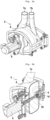
- Fig.1 a schematic view of an embodiment of an extruder 1 according to the invention is shown.
- the extruder 1 comprises a drive unit 2 with a motor and a gear for driving an extruder shaft (not shown) arranged in the extruder 1.
- Material to be processed can be introduced into the process zone 4 of the extruder 1 through the inlet 3.
- the process zone 4 is made up of several barrels. In the process zone 4, the material is processed as desired by means of an extruder screw.
- the processed material enters the cutting apparatus 5 from the extruder 1.
- the cutting apparatus 5 comprises a housing 6, an inlet pipe 7b arranged on the housing 6 and an outlet pipe 7a arranged on the housing 6.
- the inlet pipe 7b and outlet pipe 7a are inclined towards each other in their lower sections.
- a motor 8 is provided for operating a cutting tool arranged in the cutting apparatus 5, not shown here.
- FIG. 2a is a schematic view of an embodiment of a cutting apparatus 5 according to the invention in the closed state.
- the housing 6 is cylindrical or alternatively rounded.
- Inlet pipe 7b and outlet pipe 7a are arranged on top of the housing 6 such that an imaginary line through an outer edge of the inlet pipe 7b and the outlet pipe 7a is tangent to the cylindrical housing 6. This is explained below in Fig. 3a explained in more detail.
- FIG. 2b a schematic sectional view of an embodiment of a cutting apparatus 5 according to the invention is shown.
- the housing 6 there is an interior space 6a into which the inlet pipe 7b (not shown) and the outlet pipe 7a open from above and obliquely into opposite lateral areas of the interior space 6a.
- a product inlet 9 At one end of the cutting apparatus 5 there is a product inlet 9 through which material from the extruder 1 can be introduced into the interior space 6a.
- a cutting tool 10 preferably coaxial with the product inlet 9.
- FIG. 3a is a front view of an embodiment of a cutting apparatus 5 according to the invention. It can be seen that the inlet pipe 7b and outlet pipe 7a are located on top of the housing 6 are arranged such that an imaginary line (shown here in dashed lines) through an outer edge of the inlet pipe 7b and the outlet pipe 7a is tangent to the cylindrical housing 6.
- an imaginary line shown here in dashed lines
- Fig. 3b is a side view of an embodiment and in Fig. 3c a plan view of an embodiment of a cutting apparatus 5 according to the invention is shown. It can be seen that the inlet pipe 7b and outlet pipe 7a are arranged slightly offset from one another in the longitudinal direction of the cutting apparatus.
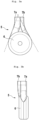
- Fig.4 a schematic representation of the cyclone flow in the cutting device 5 is shown. Air flows through the inlet pipe 7b at an angle into the interior 6a and along the rounded or cylindrical surface of the interior 6a to the outlet pipe 7a, where the air (together with shredded material) leaves the cutting device 5. The cutting tool 10 is also shown.
Landscapes
- Engineering & Computer Science (AREA)
- Life Sciences & Earth Sciences (AREA)
- Chemical & Material Sciences (AREA)
- Food Science & Technology (AREA)
- Polymers & Plastics (AREA)
- Mechanical Engineering (AREA)
- Manufacturing & Machinery (AREA)
- Processing And Handling Of Plastics And Other Materials For Molding In General (AREA)
- Formation And Processing Of Food Products (AREA)
Abstract
Description
- Die vorliegende Erfindung betrifft einen Schneidapparat für einen Extruder, insbesondere einen Extruder zur Herstellung eines Nahrungsmittels oder Tierfutters.
- Extruder sind Maschinen, in denen Materialien wie Polymere, Elastomere oder proteinhaltige Mischungen für die Herstellung von Lebensmitteln einschliesslich Cerealien, Snacks, Tierfutter und alternativer Nahrungsmittel unter gewünschten Druck- und Temperaturbedingungen behandelt werden können. Ein typischer Extruder umfasst mindestens eine Extruderschneckenwelle, wobei jede der Extruderschneckenwellen einen Satz von Extruderschneckenelementen aufweist, die auf einer Tragwelle montiert sind. Die Extruderschneckenwellen sind in einem Zylinder untergebracht, welcher als Barrel bezeichnet wird. Ein Extruder umfasst üblicherweise mehrere Barrels, die Ende an Ende miteinander verbunden sind. Mehrere Barrels sind erforderlich, um die verschiedenen in dem Extruder durchzuführenden Prozesse wie Fördern, Kneten, Mischen, Entgasen, Dosieren und dergleichen auszuführen.
- Für verschiedene Anwendungen muss am Ausgang des Extruders ein Schneidapparat angeordnet werden. Dabei handelt es sich um eine Einheit, welche ein Gehäuse und ein im Gehäuse angeordnetes Schneidwerkzeug umfasst. Das Schneidwerkzeug umfasst üblicherweise ein oder mehrere Messer, welches mittels eines Motors in eine Drehbewegung versetzt werden und in den Schneidapparat eintretendes Extrudat zerkleinern können.
- Ein Extruder mit Schneidwerkzeug ist beispielsweise aus der
EP-3 539 748 A1 bekannt. Derartige Extruder sind zudem kommerziell erhältlich, wie beispielsweise der BCTL POLYtwin™ der Firma Bühler. Der Schneidapparat ist hierbei vorzugsweise über eine befestigungsplatte mit dem Extruder verbunden und kann beispielsweise zu Reinigungszwecken seitlich verschoben werden, wodurch der Extruderausgang zugänglich wird. - Um das zerkleinerte Material aus dem Schneidapparat zu entfernen, wird üblicherweise ein Luftstrom durch den Schneidapparat geleitet, welcher das Material durch eine unten am Schneidapparat angeordnete Auslassöffnung mit Unterstützung der Schwerkraft austrägt.
- Diese bekannte Ausgestaltung eines Schneidapparats weist den Nachteil auf, dass unterhalb des Schneidwerkzeugs ein Rohr oder ein Schlauch angeordnet werden muss, welcher mit der Auslassöffnung verbunden ist und das durch den Luftstrom ausgetragene Material aufnimmt und weiterleitet. Dies erschwert die Reinigung des Gebäudes, in welchem der Extruder installiert ist. Während Schläuche flexibler und somit zu Reinigungszwecken einfacher umpositioniert werden könne, sind Rohre aufgrund ihrer glatten Oberfläche hygienischer, aber auch weniger einfach umpositionierbar.
- Weiterhin erfolgt das Austragen des zerkleinerten Materials aus dem Schneidapparat bei dieser Ausgestaltung dadurch, dass ein Luftstrom von oben in den Schneidapparat eingeleitet wird, diesen vertikal nach unten durchströmt, dabei zerkleinertes Material aufnimmt und den Schneidapparat mit dem Material unten verlässt. Dies ist keine optimale Strömungsführung, unter anderem weil der Luftstrom eine Belastung auf das zerkleinerte Material ausübt. Das extrudierte Material kann durch den Aufprall an den Gehäusewänden deformiert werden und dadurch die Produktqualität mindern.
- Es war die Aufgabe der vorliegenden Erfindung, einen Schneidapparat für einen Extruder bereitzustellen, mit welchem die vorstehend beschriebenen Nachteile des Stands der Technik überwunden werden.
- Diese Aufgabe wird durch die vorliegende Erfindung gelöst.
- Im Detail betrifft die vorliegende Erfindung einen Schneidapparat für einen Nahrungs- oder Futtermittelextruder, umfassend ein Gehäuse mit einem zylindrischen Innenraum,
- ein Schneidwerkzeug,
- einen Produkteinlass an einem Ende des Gehäuses, wobei das Schneidwerkzeug und der Produkteinlass koaxial im Gehäuse angeordnet sind,
- ein Einlassrohr und ein Auslassrohr,
- dadurch gekennzeichnet, dass das Einlassrohr und das Auslassrohr von oben in das Gehäuse münden und sich vom Gehäuse nach oben weg erstrecken, und zumindest in einem Abschnitt, der mit dem Gehäuse verbunden ist, schräg in gegenüberliegende seitliche Bereiche des Innenraums münden.
- Der erfindungsgemässe Schneidapparat zeichnet sich dadurch aus, dass das Einlassrohr und das Auslassrohr für durch den Schneidapparat zu leitende Luft so angeordnet sind, dass die Luft in den Schneidapparat von oben oder seitlich, vorzugsweise von oben eingeleitet beziehungsweise abgesaugt wird und den Schneidapparat nach oben oder seitlich, vorzugsweise nach oben verlässt. Dies hat den Vorteil, dass Schläuche und Rohre, welche mit dem Einlassrohr und dem Auslassrohr zu verbinden sind, oberhalb oder seitlich, vorzugsweise oberhalb des Schneidapparats angeordnet werden können. Der Raum unterhalb des Schneidapparats bleibt frei und kann einfach gereinigt oder für andere Zwecke verwendet werden.
- Zudem sind das Einlassrohr und das Auslassrohr derart angeordnet, dass ein hindurch geleiteter Luftstrom im Schneidapparat eine Zyklonströmung ausbildet. Dies führt zu einer schonenderen und effizienteren Austragung des zerkleinerten Materials aus dem Schneidapparat. Ferner prallt das extrudierte Material nicht frontal gegen die Gehäusewände, sondern gleitet durch die rotierende Bewegung des Luftstroms und Rundungen des Gehäuses an den Gehäusewänden vorbei.
- Eine nach oben ausgerichtete Anordnung von Einlassrohr und Auslassrohr wurde in einem Gerät der Firma Frazer-Nash realisiert (https://www.youtube.com/watch?v=Rd2NnqRNFDU). Allerdings wurden dort das Einlassrohr und das Auslassrohr nicht derart angeordnet, dass innerhalb des Schneidapparats eines Zyklonströmung ausgebildet wird. Die Luft wird vertikal von oben eingeleitet, erfährt am Boden des Schneidapparats eine Strömungsumkehr und verlässt den Schneidapparat vertikal nach oben. Die mit einer vertikalen Luftströmung durch den Schneidapparat verbundenen Nachteile wurden nicht erkannt. Zudem sind bei diesem Gerät das Schneidwerkzeug und der Produkteinlass nicht koaxial im Gehäuse des Schneidapparats angeordnet. Das Material erfährt keine schonende Beförderung, sondern prallt auf Begrenzungsflächen.
- Um die Zyklonströmung zu erzeugen, muss das Gehäuse des Schneidapparats einen zylindrischen Innenraum aufweisen. Die Luft kann an der Innenseite der Mantelfläche des zylindrischen Innenraums entlang strömen.
- Einlassrohr und das Auslassrohr sind vorzugsweise derart an dem Gehäuse des Schneidapparats angeordnet, dass sie schräg und tangential zum Gehäusemantel in gegenüberliegende seitliche Bereiche des Innenraums münden. Auf diese Weise kommt Luft aus dem Einlassrohr in Kontakt mit der Innenseite der Mantelfläche des zylindrischen Innenraums, strömt an dieser entlang und verlässt den Schneidapparat ohne weitere Umlenkung. Die Anordnung von Einlassrohr und Auslassrohr unterstützt somit die Erzeugung einer Zyklonströmung im Schneidapparat, genauer in dessen zylindrischem Innenraum. Unkontrollierte Verwirbelungen des Luftstroms werden vermieden.
- Die vorstehend beschriebene Anordnung von Einlassrohr und Auslassrohr wird vorzugsweise dadurch erreicht, dass die beiden Rohre von oben in das Gehäuse münden und zumindest in einem Abschnitt, der mit dem Gehäuse verbunden ist, zueinander hin geneigt sind. Der Neigungswinkel liegt vorzugsweise zwischen 30 und 80°, besonders bevorzugt zwischen 45 und 70°.
- Es ist hierbei bevorzugt, dass die Rohre in einem Abschnitt, der mit dem Gehäuse verbunden ist, zueinander hin geneigt sind. Dieser Abschnitt erstreckt sich vorzugsweise bis zu einer Höhe von 20 cm, besonders bevorzugt bis zu einer Höhe von 15 cm, ausgehend von der Aussenseite des Gehäuses des Schneidapparats. Daran anschliessend werden Einlassrohr und Auslassrohr vorzugsweise vertikal nach oben vom Schneidapparat weg geführt.
- Das Einlassrohr und das Auslassrohr werden vorzugsweise aus einem Material gefertigt, welches üblicherweise für derartige Rohre eingesetzt wird. Beispielhaft sei ein Metall oder eine metallhaltige Verbindung wie Edelstahl genannt.
- Einlassrohr und Auslassrohr haben einen Durchmesser, wie er üblicherweise auch für die Verbindungsrohre und Verbindungsschläuche aus dem Stand der Technik verwendet werden. Vorzugsweise liegen die Durchmesser im Bereich von 50-400 mm, besonders bevorzugt 60-350 mm.
- Gemäss einer bevorzugten erfindungsgemässen Ausführungsform kann das Auslassrohr einen Durchmesser aufweisen, welcher den Durchmesser des Einlassrohres überschreitet. Auf diese Weise kann ein effizientes Austragen des zerkleinerten Materials gewährleistet werden. Vorzugsweise ist der Durchmesser des Auslassrohres 10-50% grösser als der Durchmesser des Einlassrohres.
- Zur Erzeugung der Zyklonströmung ist es erforderlich, dass der Innenraum des Gehäuses des Schneidapparats zylindrisch ist. Gemäss einer bevorzugten Ausführungsform der vorliegenden Erfindung ist jedoch das Gehäuse des Schneidapparats ebenfalls gerundet, insbesondere zylindrisch, das heisst es hat bevorzugt eine zylindrische Aussenform. Auf diese Weise wird ein hygienisches Design realisiert und unnötiger Totraum im Gehäuse vermieden; die Gehäusewand kann als Begrenzung des Innenraums verwendet werden.
- Bei dieser bevorzugten Ausführungsform sind das Einlassrohr und das Auslassrohr derart am Gehäuse des Schneidapparats angeordnet, dass eine gedachte Linie durch eine äussere Kante des Einlassrohrs und des Auslassrohrs in Bezug auf das zylindrische Gehäuse eine Tangente ist. Unter einer Aussenkante ist hierbei die Kante eines Rohres zu verstehen, welche vom anderen Rohr am weitesten entfernt und somit in einer Vorderansicht aus den Schneidapparat am weitesten aussen angeordnet ist.
- Das Gehäuse ist vorzugsweise aus einem Material gefertigt, welches üblicherweise für Gehäuse derartiger Schneidapparate eingesetzt wird. Beispielhaft sei ein Metall oder eine metallhaltige Verbindung wie Edelstahl genannt.
- Der erfindungsgemässe Schneidapparat weist übliche Dimensionen wie analoge Geräte aus dem Stand der Technik auf.
- In dem Schneidapparat ist ein Schneidwerkzeug angeordnet. Vorzugsweise handelt es sich um ein oder mehrere Messer, die drehbar in dem Innenraum des Gehäuses des Schneidapparats angeordnet sind. Dies ist herkömmlich bekannt.
- Das Schneidwerkzeug ist mit einem Motor verbunden, welcher das Schneidwerkzeug in die gewünschte Bewegung versetzen kann, beispielsweise in die vorstehend beschriebene Drehbewegung. Der Motor ist an einem Ende des Schneidapparats angeordnet und beispielsweise über eine Welle mit dem Schneidwerkzeug verbunden. Dies ist hinlänglich bekannt.
- Der Schneidapparat weist zudem einen Produkteinlass in Form einer Öffnung auf, welche fluidisch mit dem Auslass eines Extruders verbunden werden kann, sodass extrudiertes Material aus dem Extruder in den Schneidapparat gelangen kann. Vorzugsweise ist dieser Produkteinlass in der Seitenfläche des Schneidapparats angeordnet, welche der Seitenfläche gegenüberliegt, an welcher der Motor angeordnet ist.
- Gemäss einer bevorzugten Ausführungsform der vorliegenden Erfindung ist der Produkteinlass im Schneidapparat derart ausgestaltet, dass der Extruderkopf (d.h. das antriebsabgewandte Ende des Extruders) mit dem Extruderauslass durch diese Öffnung in den Innenraum des Gehäuses des Schneidapparats hineinragen kann. Auf diese Weise kann extrudiertes Material direkt in den Innenraum gelangen, ohne eine Berührung mit einer Kante des Produkteinlasses zu erfahren.
- Gemäss einer besonders bevorzugten Ausführungsform der vorliegenden Erfindung sind der Produkteinlass in den Schneidapparat und das Schneidwerkzeug im Schneidapparat koaxial angeordnet. Mit anderen Worten hat der Produkteinlass in den Schneidapparat einen runden Querschnitt mit einer Zentralachse und das Schneidwerkzeug eine kreisförmige Form mit ebenfalls einer Zentralachse, wobei beide Zentralachsen zusammenfallen. Das Schneidwerkzeug ist hierbei direkt vor dem Produkteinlass angeordnet, sodass in den Innenraum des Gehäuses des Schneidapparats eintretendes Material direkt und auf schonende Weise ohne Kontakt mit Flächen zum Schneidwerkzeug gelangt. Es ist aber auch eine etwas versetzte Anordnung des Schneidwerkzeugs denkbar, so dass ein exzentrisches Schneiden durchgeführt werden kann.
- Der erfindungsgemässe Schneidapparat weist Mittel zur Befestigung des Schneidapparats an einem Extruder auf. Vorzugsweise handelt es sich um lösbare Befestigungsmittel wie Schrauben, damit der Schneidapparat beispielsweise für Wartungszwecke oder zum Austausch von dem Extruder entfernt werden kann. Vorzugsweise kann der erfindungsgemässe Schneidapparat über eine Befestigungsplatte mit dem Extruder oder einem am Extruder angeordneten Kühlwerkzeug lösbar verbunden sein, wie dies beispielsweise in der
EP-3 539 748 A1 beschrieben ist. - Gemäss einer weiteren bevorzugten Ausführungsform ist der erfindungsgemässe Schneidapparat aufklappbar. Das Gehäuse des Schneidapparats besteht bei einer derartige Ausführungsform vorzugsweise aus zwei Teilen, welche mittels eines Verschlusses miteinander verbunden sind. Wir der Verschluss gelöst, kann ein Teil über ein Scharnier vom anderen Teil weggeschwenkt werden. Dadurch wird der Innenraum des Schneidapparats zugänglich, beispielsweise für Reinigungs- oder Wartungszwecke.
- Der erfindungsgemässe Schneidapparat kann an jedem herkömmlichen Extruder angeordnet werden.
- Die vorliegende Erfindung betrifft somit auch einen Extruder, umfassend einen vorstehend beschriebenen erfindungsgemässen Schneidapparat.
- Extruder sind hinlänglich bekannt. Es wird z.B. auf die
WO 2012/158023 A1 oder auf die Extruder, insbesondere Doppelschneckenextruder, von Bühler verwiesen. Solche Extruder haben vorzugsweise ein L/D-Verhältnis (Gesamtlänge zu Schneckendurchmesser) im Bereich von 12 -60, vorzugsweise 20 bis 40. Erfindungsgemäß werden die Extruder vorzugsweise mit 100 bis 1000 U/min, besonders bevorzugt mit 200 bis 600 U/min und besonders bevorzugt mit 250 bis 350 U/min betrieben. - Der erfindungsgemässe Extruder umfasst einen Motor mit einem Getriebe, um die Extruderschnecken anzutreiben. Zu diesem Zweck ist die Tragwelle jeder vorhandenen Extruderschnecke operativ mit dem Getriebe verbunden. Dies kann auf herkömmlich bekannte Art erfolgen.
- Der erfindungsgemässe Extruder umfasst weiterhin ein Extrudergehäuse mit einer im Gehäuse befindlichen Prozesszone und einem Einlass und Auslass. Das Extrudergehäuse umfasst vorzugsweise 2 bis 20 Barrel, bevorzugter 2 bis 15 Barrels. Die Barrels sind vorzugsweise stirnseitig miteinander verbunden und bilden zusammen das Extrudergehäuse.
- Das Extrudergehäuse (beziehungsweise jedes der das Extrudergehäuse bildenden Barrels) weist eine Durchgangsbohrung auf. Die Durchgangsbohrung durchläuft das Extrudergehäuse axial durch dessen gesamte Länge. Innerhalb dieser Durchgangsbohrung befindet sich die Prozesszone des Extruders.
- Das Gehäuse des Extruders ist vorzugsweise temperaturgesteuert. Das zu extrudierende Material wird unter Druck (üblicherweise 1 bis 400 bar, vorzugsweise 1 bis 200 bar) geknetet, um eine homogene Mischung zu bilden. Dabei wird in der Regel ein Energieaufwand von 10 bis 150 Wh/kg, vorzugsweise 10 bis 120 Wh/kg, besonders bevorzugt 15 bis 30 Wh/kg betrieben.
- Der Einlass des Extruders dient zum Einbringen von Rohstoffen in einen ersten Abschnitt des Extruders. Dieser Einlass mündet in die Prozesszone. Der Einlass befindet sich üblicherweise und bevorzugt auf dem Extrudergehäuse, so dass Material unter Einwirkung der Schwerkraft in das Extrudergehäuse, genauer in der Prozesszone des Extruders, gelangen kann.
- Das zu extrudierende Material kann direkt durch den Einlass in die Prozesszone gegeben werden. Vorzugsweise befindet sich oberhalb des Einlasses eine Dosiervorrichtung, mit welcher das zu extrudierende Material dosiert und gegebenenfalls vermischt wird, bevor es durch den Einlass geführt wird. Erfindungsgemäss bevorzugt kann das zu extrudierende Material vorgängig in einem herkömmlichen Vorkonditionierer vorbehandelt und von diesem, beispielsweise mittels einer herkömmlichen Förderschnecke, dem Einlass zugeführt werden.
- Am dem zum Einlass entfernten Ende der Prozesszone befindet sich ein Auslass, durch welchen das extrudierte Material den Extruder verlässt. Der Auslass ist mit der Prozesszone verbunden.
- Der Extruder verfügt typischerweise auch über eine Wasser-, eine Öl- und gegebenenfalls eine Dampfzufuhrleitung.
- Gemäß einer bevorzugten Ausführungsform der vorliegenden Erfindung kann am Ausgang des Extruders ein Kühlwerkzeug wie eine Kühldüse vorgesehen sein. Kühlwerkzeuge für Extruder sind hinreichend bekannt. Zwischen Extruder und Kühlwerkzeug kann vorzugsweise eine bekannte Verteilereinheit angeordnet sein.
- Wie vorstehend beschrieben ist der erfindungsgemässe Schneidapparat am Auslassende des Extruders oder am Auslassende eines am Auslassende des Extruders bereitgestellten Kühlwerkzeugs angeordnet, sofern ein Kühlwerkzeug vorhanden ist.
- Für den Fall, dass ein Kühlwerkzeug vorhanden ist, gelten die vorstehenden Ausführungen betreffend den Extruderkopf analog für das Ende des Kühlwerkzeugs. Mit andere Worten ragt dann vorzugsweise ein Ende des Kühlwerkzeugs durch den Produkteinlass des Schneidapparats in den Innenraum des Gehäuses des Schneidapparats.
- Wie vorstehend ausgeführt ist der erfindungsgemässe Schneidapparat über eine Befestigungsplatte mit dem Extruder oder dem Kühlwerkzeug lösbar verbunden.
- Der Schneidapparat kann ferner einen Träger aufweisen, mit welchem der Schneidapparat auf dem Boden eines Gebäudes wie einer Halle abgestützt werden kann.
- Die vorliegende Erfindung betrifft weiterhin eine Extrusionsanlage, umfassend einen Extruder gemäss der vorstehenden Beschreibung sowie mindestens eine Einheit ausgewählt aus der Gruppe bestehend aus einer mit dem Einlassrohr des Schneidapparats in Verbindung stehenden Gaseinleitungseinheit und einer mit dem Auslassrohr des Schneidapparats in Verbindung stehenden Gasausleitungseinheit.
- Wie vorstehend beschrieben wird während des bestimmungsgemässen Gebrauchs im Schneidapparat eine Zyklonströmung erzeugt. Eine Zyklonströmung ist eine kreisförmige Strömung um einen Mittelpunkt, analog einem Wirbelsturm.
- Um die Zyklonströmung zu erzeugen, kann gemäss einer Ausführungsform der vorliegenden Erfindung Luft mit Hilfe einer Gaseinleitungseinheit durch das Einlassrohr in den Innenraum des Schneidapparats geleitet werden. Üblicherweise erfolgt dies durch Einleiten eines Druckluftstroms. Die Gaseinleitungseinheit ist daher vorzugsweise eine Einheit, in welcher Luft komprimiert und unter Druck freigesetzt werden kann. Beispielhaft sei eine Pumpe genannt.
- Gemäss einer anderen Ausführungsform der vorliegenden Erfindung kann die Zyklonströmung aber auch erzeugt werden, indem Luft aus dem Innenraum des Gehäuses des Schneidapparats durch das Auslassrohr abgesaugt wird. Die Gasausleitungseinheit ist daher bevorzugt eine Luftansaugeinheit wie eine Pumpe.
- Auch wenn die Zyklonströmung durch Einleiten von Druckluft in den Innenraum des Gehäuses des Schneidapparats erzeugt wird, kann eine vorstehend beschriebene Gasausleitungseinheit bereitgestellt sein, um das Austragen des Materials aus dem Schneidapparat zu unterstützen.
- Das Einlassrohr und das Auslassrohr können mit bekannten Zuführungs-, Abführungs- oder Weiterverarbeitungseinrichtungen verbunden sein. Da erfindungsgemäss Einlassrohr und Auslassrohr sich seitlich oder besonders bevorzugt nach oben vom Schneidapparat weg erstrecken, können die entsprechenden Verbindungsleitungen oberhalb der Extrusionsanlage angeordnet sein, ohne dass sie Platz am Boden des Gebäudes einnehmen, in welchem die Extrusionsanlage aufgestellt ist. Dies ermöglicht eine leichtere Reinigung des Bodens unterhalb der Extrusionsanlage, weil keine Rohre oder Schläuche auf dem Boden liegen.
- Die vorliegende Erfindung betrifft weiterhin ein Verfahren zur Herstellung eines extrudierten Materials mit einem Extruder gemäss einem der Ansprüche 5 bis 9, umfassend die Schritte:
- Extrusion des Materials im Extruder,
- Überführung des extrudierten Materials aus dem Extruder in den Schneidapparat,
- Schneiden des extrudierten Materials in dem Schneidapparat, und
- Abführung des extrudierten Materials aus dem Schneidapparat mittels einer Zyklonströmung.
- Die Zyklonströmung kann wie vorstehend beschrieben durch Einleiten von Gas in den Innenraum des Gehäuses des Schneidapparats durch das Einlassrohr des Schneidapparats erzeugt werden.
- Alternativ kann die Zyklonströmung wie vorstehend beschrieben durch Herausziehen von Gas aus dem Innenraum des Gehäuses des Schneidapparats durch das Auslassrohr des Schneidapparats erzeugt werden.
- Erfindungsgemäss bevorzugt wird der Schneidapparat mit Heissluft betrieben, welche beispielsweise eine Temperatur im Bereich von 20 bis 150°C, vorzugsweise von 50 bis 100°C aufweist.
- Erfindungsgemäss können sämtliche Nahrungsmittel oder Tierfutter hergestellt werden, welche üblicherweise durch Extrusion hergestellt werden. Beispielsweise sind proteinhaltige Mischungen für die Herstellung von Lebensmitteln einschliesslich Cerealien, Snacks, Tierfutter und alternativer Nahrungsmittel (wie alternativer Fleisch- und Fischprodukte) genannt.
- Die vorliegende Erfindung wird nachfolgend anhand von nicht einschränkenden Ausführungsbeispielen unter Bezugnahme auf Figuren näher beschrieben. In den Figuren bezeichnen gleiche Bezugszeichen gleiche Elemente. Es zeigen:
- Fig. 1
- eine schematische Ansicht einer Ausführungsform eines erfindungsgemässen Extruders
- Fig. 2a
- eine schematische Ansicht einer Ausführungsform eines erfindungsgemässen Schneidapparats im geschlossenen Zustand
- Fig. 2b
- eine schematische Ansicht eines Schnitts durch eine Ausführungsform eines erfindungsgemässen Schneidapparats
- Fig. 3a
- eine Vorderansicht einer Ausführungsform eines erfindungsgemässen Schneidapparats
- Fig. 3b
- eine Seitenansicht einer Ausführungsform eines erfindungsgemässen Schneidapparats
- Fig. 3c
- eine Draufsicht auf eine Ausführungsform eines erfindungsgemässen Schneidapparats
- Fig. 4
- eine schematische Darstellung der Zyklonströmung im Schneidapparat
- In
Fig. 1 ist eine schematische Ansicht einer Ausführungsform eines erfindungsgemässen Extruders 1 gezeigt. Der Extruder 1 umfasst eine Antriebseinheit 2 mit einem Motor und einem Getriebe zum Antreiben einer im Extruder 1 angeordneten, nicht gezeigten Extruderwelle. Durch den Einlass 3 kann zu verarbeitendes Material in die Prozesszone 4 des Extruders 1 eingeführt werden. Die Prozesszone 4 ist aus mehreren Barrels aufgebaut. In der Prozesszone 4 wird das Material mittels einer Extruderschnecke wie gewünscht bearbeitet. - Das bearbeitete Material tritt aus dem Extruder 1 in den Schneidapparat 5 ein. Der Schneidapparat 5 umfasst ein Gehäuse 6, ein auf dem Gehäuse 6 angeordnetes Einlassrohr 7b und ein auf dem Gehäuse 6 angeordnetes Auslassrohr 7a. Einlassrohr 7b und Auslassrohr 7a sind in ihren unteren Abschnitten zueinander hin geneigt. An dem vom Extruder 1 abgewandten Ende des Schneidapparats 5 ist ein Motor 8 zum Betreiben eines im Schneidapparat 5 angeordneten, hier nicht gezeigten Schneidwerkzeugs bereitgestellt.
- In
Fig. 2a ist eine schematische Ansicht einer Ausführungsform eines erfindungsgemässen Schneidapparats 5 im geschlossenen Zustand gezeigt. Wie inFig. 1 ist das Gehäuse 6 zylindrisch oder alternativ gerundet. Einlassrohr 7b und Auslassrohr 7a sind oben auf dem Gehäuse 6 derart angeordnet, dass eine gedachte Linie durch eine äussere Kante des Einlassrohrs 7b und des Auslassrohrs 7a in Bezug auf das zylindrische Gehäuse 6 eine Tangente ist. Dies wird nachstehend inFig. 3a näher erläutert. - In
Fig. 2b ist eine schematische Schnittansicht einer Ausführungsform eines erfindungsgemässen Schneidapparats 5 gezeigt. Im Gehäuse 6 befindet sich ein Innenraum 6a, in welchen das Einlassrohr 7b (nicht gezeigt) und das Auslassrohr 7a von oben und schräg in gegenüberliegende seitliche Bereiche des Innenraums 6a münden. An einem Ende des Schneidapparats 5 ist ein Produkteinlass 9 angeordnet, durch welchen Material aus dem Extruder 1 in den Innenraum 6a eingeführt werden kann. Im Innenraum 6a ist weiterhin ein Schneidwerkzeug 10 bereitgestellt, vorzugsweise koaxial mit dem Produkteinlass 9. - In
Fig. 3a ist eine Vorderansicht einer Ausführungsform eines erfindungsgemässen Schneidapparats 5 gezeigt. Es ist zu erkennen, dass Einlassrohr 7b und Auslassrohr 7a oben auf dem Gehäuse 6 derart angeordnet sind, dass eine gedachte Linie (hier gestrichelt dargestellt) durch eine äussere Kante des Einlassrohrs 7b und des Auslassrohrs 7a in Bezug auf das zylindrische Gehäuse 6 eine Tangente ist. - In
Fig. 3b ist eine Seitenansicht einer Ausführungsform und inFig. 3c eine Draufsicht auf eine Ausführungsform eines erfindungsgemässen Schneidapparats 5 gezeigt. Es ist zu erkennen, dass Einlassrohr 7b und Auslassrohr 7a in Längsrichtung des Schneidapparats etwas versetzt zueinander angeordnet sind. - In
Fig. 4 ist eine schematische Darstellung der Zyklonströmung im Schneidapparat 5 gezeigt. Luft strömt durch das Einlassrohr 7b schräg in den Innenraum 6a und entlang der gerundeten bzw. zylindrischen Mantelfläche des Innenraums 6a bis zum Auslassrohr 7a, wo die Luft (zusammen mit zerkleinertem Material) den Schneidapparat 5 verlässt. Weiterhin ist das Schneidwerkzeug 10 dargestellt.
Claims (13)
- Schneidapparat (5) für einen Nahrungs- oder Futtermittelextruder (1), umfassendein Gehäuse (6) mit einem zylindrischen Innenraum (6a),ein Schneidwerkzeug (10),einen Produkteinlass (9) an einem Ende des Gehäuses (6),wobei das Schneidwerkzeug (10) und der Produkteinlass (9) koaxial im Gehäuse (6) angeordnet sind,ein Einlassrohr (7b) und ein Auslassrohr (7a),dadurch gekennzeichnet, dass das Einlassrohr (7b) und das Auslassrohr (7a) von oben in das Gehäuse (6) münden und sich vom Gehäuse (6) nach oben weg erstrecken, und zumindest in einem Abschnitt, der mit dem Gehäuse (6) verbunden ist, schräg in gegenüberliegende seitliche Bereiche des Innenraums (6a) münden.
- Schneidapparat nach Anspruch 1, dadurch gekennzeichnet, dass das Gehäuse (6) gerundet, insbesondere zylindrisch ist.
- Schneidapparat nach Anspruch 2, dadurch gekennzeichnet, dass eine gedachte Linie durch eine äussere Kante des Einlassrohrs (7b) und des Auslassrohrs (7a) in Bezug auf das zylindrische Gehäuse (6) eine Tangente ist.
- Schneidapparat nach einem der Ansprüche 1 bis 3, dadurch gekennzeichnet, dass der Schneidapparat (5) einen Motor (8) zum Antrieb des Schneidwerkzeugs (10) umfasst.
- Extruder (1), umfassend einen Schneidapparat (5) gemäss einem der Ansprüche 1 bis 4.
- Extruder nach Anspruch 5, dadurch gekennzeichnet, dass der Schneidapparat (5) am Auslassende des Extruders (1) oder am Auslassende eines am Auslassende des Extruders (1) bereitgestellten Kühlwerkzeugs angeordnet ist.
- Extruder nach Anspruch 6, dadurch gekennzeichnet, dass der Schneidapparat (5) über eine Befestigungsplatte mit dem Extruder (1) oder dem Kühlwerkzeug lösbar verbunden ist.
- Extruder nach einem der Ansprüche 5 bis 7, dadurch gekennzeichnet, dass das Einlassrohr (7b) und das Auslassrohr (7a) des Schneidapparats (5) mit Leitungen oder Rohren verbunden sind, welche vom Schneidapparat (5) nach oben wegführen.
- Extruder nach einem der Ansprüche 5 bis 8, dadurch gekennzeichnet, dass sich das Ende des Extruders (1) oder des Kühlwerkzeugs in das Gehäuse (6) des Schneidapparats (5) erstreckt.
- Extrusionsanlage, umfassend einen Extruder (1) gemäss einem der Ansprüche 5 bis 9 sowie mindestens eine Einheit ausgewählt aus der Gruppe bestehend aus einer mit dem Einlassrohr (7b) des Schneidapparats (5) in Verbindung stehenden Gaseinleitungseinheit und einer mit dem Auslassrohr (7a) des Schneidapparats (5) in Verbindung stehenden Gasausleitungseinheit.
- Verfahren zur Herstellung eines extrudierten Materials mit einem Extruder (1) gemäss einem der Ansprüche 5 bis 9, umfassend die Schritte:- Extrusion des Materials im Extruder (1),- Überführung des extrudierten Materials aus dem Extruder (1) in den Schneidapparat (5),- Schneiden des extrudierten Materials in dem Schneidapparat (5), und- Abführung des extrudierten Materials aus dem Schneidapparat (5) mittels einer Zyklonströmung.
- Verfahren nach Anspruch 11, dadurch gekennzeichnet, dass die Zyklonströmung durch Einleiten von Gas in den Innenraum (6a) des Gehäuses (6) des Schneidapparats (5) durch das Einlassrohr (7a) des Schneidapparats (5) erzeugt wird.
- Verfahren nach Anspruch 11, dadurch gekennzeichnet, dass die Zyklonströmung durch Herausziehen von Gas aus dem Innenraum (6a) des Gehäuses (6) des Schneidapparats (5) durch das Auslassrohr (7a) des Schneidapparats (5) erzeugt wird.
Priority Applications (4)
| Application Number | Priority Date | Filing Date | Title |
|---|---|---|---|
| DK23159982.0T DK4424489T3 (da) | 2023-03-03 | 2023-03-03 | Skæreapparat til ekstruder og fremgangsmåde til fremstilling af et ekstruderet materiale |
| EP23159982.0A EP4424489B1 (de) | 2023-03-03 | 2023-03-03 | Schneidapparat für extruder und verfahren zur herstellung eines extrudierten materials |
| CN202480015736.8A CN120813462A (zh) | 2023-03-03 | 2024-02-28 | 用于挤出机的切割设备和用于生产挤出材料的方法 |
| PCT/EP2024/025097 WO2024183952A1 (en) | 2023-03-03 | 2024-02-28 | Cutting apparatus for extruder and process for producing an extruded material |
Applications Claiming Priority (1)
| Application Number | Priority Date | Filing Date | Title |
|---|---|---|---|
| EP23159982.0A EP4424489B1 (de) | 2023-03-03 | 2023-03-03 | Schneidapparat für extruder und verfahren zur herstellung eines extrudierten materials |
Publications (2)
| Publication Number | Publication Date |
|---|---|
| EP4424489A1 true EP4424489A1 (de) | 2024-09-04 |
| EP4424489B1 EP4424489B1 (de) | 2025-08-20 |
Family
ID=85462236
Family Applications (1)
| Application Number | Title | Priority Date | Filing Date |
|---|---|---|---|
| EP23159982.0A Active EP4424489B1 (de) | 2023-03-03 | 2023-03-03 | Schneidapparat für extruder und verfahren zur herstellung eines extrudierten materials |
Country Status (4)
| Country | Link |
|---|---|
| EP (1) | EP4424489B1 (de) |
| CN (1) | CN120813462A (de) |
| DK (1) | DK4424489T3 (de) |
| WO (1) | WO2024183952A1 (de) |
Citations (8)
| Publication number | Priority date | Publication date | Assignee | Title |
|---|---|---|---|---|
| US3343213A (en) * | 1964-03-24 | 1967-09-26 | Werner & Pfleiderer | Device for granulating thermoplastic material |
| US20100187707A1 (en) * | 2009-01-26 | 2010-07-29 | Automatik Plastics Machinery Gmbh | Method and device for granulating thermoplastic material |
| WO2012158023A1 (en) | 2011-05-13 | 2012-11-22 | Ojah B.V. | Method of making structured protein compositions |
| US20160304295A1 (en) * | 2015-04-20 | 2016-10-20 | Schenck Process Llc | Sanitary extruder hood |
| CN207290623U (zh) * | 2017-09-13 | 2018-05-01 | 东莞市三优塑料机械制造有限公司 | 一种塑料造粒风冷热切装置 |
| EP3539748A1 (de) | 2018-03-12 | 2019-09-18 | Bühler AG | Extruder zur extrusion von lebensmitteln oder futtermitteln |
| US20200215721A1 (en) * | 2017-09-29 | 2020-07-09 | Maag Automatik Gmbh | Cutting chamber housing for an underwater pelletizer |
| US20220332017A1 (en) * | 2019-08-20 | 2022-10-20 | Basf Se | Underwater granulation system, and method for granulating a polymer melt |
Family Cites Families (5)
| Publication number | Priority date | Publication date | Assignee | Title |
|---|---|---|---|---|
| US4954352A (en) * | 1988-07-27 | 1990-09-04 | Exxon Chemical Patents Inc. | Apparatus for producing particles of thermoplastic material |
| JPH06315930A (ja) * | 1993-05-10 | 1994-11-15 | Hitachi Cable Ltd | ポリオレフィン系樹脂のペレット製造方法 |
| CN201086370Y (zh) * | 2007-07-18 | 2008-07-16 | 成都中孚高分子工程有限公司 | 用于塑料挤出机拉条造粒的切粒机 |
| CN207758099U (zh) * | 2017-12-29 | 2018-08-24 | 江阴鼎言密封件有限公司 | 用于密封条加工设备的风冷装置 |
| DK3524059T3 (da) * | 2018-02-13 | 2020-10-19 | Buehler Ag | Køledyse til en ekstruder |
-
2023
- 2023-03-03 EP EP23159982.0A patent/EP4424489B1/de active Active
- 2023-03-03 DK DK23159982.0T patent/DK4424489T3/da active
-
2024
- 2024-02-28 WO PCT/EP2024/025097 patent/WO2024183952A1/en not_active Ceased
- 2024-02-28 CN CN202480015736.8A patent/CN120813462A/zh active Pending
Patent Citations (8)
| Publication number | Priority date | Publication date | Assignee | Title |
|---|---|---|---|---|
| US3343213A (en) * | 1964-03-24 | 1967-09-26 | Werner & Pfleiderer | Device for granulating thermoplastic material |
| US20100187707A1 (en) * | 2009-01-26 | 2010-07-29 | Automatik Plastics Machinery Gmbh | Method and device for granulating thermoplastic material |
| WO2012158023A1 (en) | 2011-05-13 | 2012-11-22 | Ojah B.V. | Method of making structured protein compositions |
| US20160304295A1 (en) * | 2015-04-20 | 2016-10-20 | Schenck Process Llc | Sanitary extruder hood |
| CN207290623U (zh) * | 2017-09-13 | 2018-05-01 | 东莞市三优塑料机械制造有限公司 | 一种塑料造粒风冷热切装置 |
| US20200215721A1 (en) * | 2017-09-29 | 2020-07-09 | Maag Automatik Gmbh | Cutting chamber housing for an underwater pelletizer |
| EP3539748A1 (de) | 2018-03-12 | 2019-09-18 | Bühler AG | Extruder zur extrusion von lebensmitteln oder futtermitteln |
| US20220332017A1 (en) * | 2019-08-20 | 2022-10-20 | Basf Se | Underwater granulation system, and method for granulating a polymer melt |
Also Published As
| Publication number | Publication date |
|---|---|
| EP4424489B1 (de) | 2025-08-20 |
| DK4424489T3 (da) | 2025-09-29 |
| WO2024183952A1 (en) | 2024-09-12 |
| CN120813462A (zh) | 2025-10-17 |
Similar Documents
| Publication | Publication Date | Title |
|---|---|---|
| AT507971B1 (de) | Kunststoff-extruder | |
| EP3564005B1 (de) | Misch- und knetmaschine, und deren verwendung | |
| DE112015002161T5 (de) | Extruderschnecke, Extruder und Extrusionsverfahren | |
| EP3257644A1 (de) | Verfahren für das devulkanisieren von altgummi | |
| EP0617050A1 (de) | Verfahren und Einrichtung zum Herstellen eines Produktes, vorzugsweise eines geschäumten Produktes oder eines Schaumstoffmaterials aus nicht modifizierter Stärke | |
| EP3360613A1 (de) | Vorrichtung zum flockieren oder schroten von speisegetreide | |
| EP1263558B1 (de) | Aufbereitungsvorrichtung für kunststoffmaterial | |
| DE102007040645B4 (de) | Extruder, insbesondere Planetwalzenextruder mit einer Entgasungsöffnung | |
| DE102016224607A1 (de) | Silikonextrusionsanlage, Verfahren zur Silikonextrusion sowie hierdurch hergestelltes Silikonextrudat | |
| EP3473395A1 (de) | Asymmetrische dreiflüglige schneckenwelle für misch- und knetmaschine | |
| EP1543930B1 (de) | Vorrichtung zum Verarbeiten von Gummi | |
| EP4424489B1 (de) | Schneidapparat für extruder und verfahren zur herstellung eines extrudierten materials | |
| EP2572584B1 (de) | Vorrichtung und Verfahren zur Verarbeitung eines Lebensmittels, insbesondere zur Verarbeitung von Teig | |
| EP1027836B1 (de) | Verfahren und Vorrichtung zur Herstellung von Zwischenprodukten und Mischfutterprodukten für Tiere | |
| EP1920822B1 (de) | Vorrichtung und Verfahren zur kontinuierlichen Mischung und Entgasung von festen und/oder flüssigen Substanzen | |
| DE69212748T2 (de) | Apparat zum Rekuperieren heterogener Abfälle, insbesonderen heterogener Kunststoff-Abfälle | |
| DE69205797T2 (de) | Ausrichtungsverfahren und -vorrichtung für einen Ausgabetrichter, insbesondere zum Ausgaben von Zigaretten. | |
| EP0436786A2 (de) | Verfahren und Vorrichtung zum Herstellen von Extrudatteilchen | |
| EP2707206B1 (de) | Pressschneckenseparator | |
| DE10058377A1 (de) | Verfahren und Vorrichtung zum Herstellen von Wurstbrät | |
| DE3130968A1 (de) | Verfahren und vorrichtung zur kontinuierlichen herstellung von beluefteten zuckermassen | |
| DE69807553T2 (de) | Vorrichtung zum Herstellen keramischer Gegenstände | |
| EP3020974B1 (de) | System zur förderung viskoser medien, verfahren zum betreiben eines solchen systems und fördereinheit hierfür | |
| EP3656523B1 (de) | Misch- und knetmaschine mit wirksamer entlüftung im bereich der zuführung, und darauf bezogenes verfahren | |
| EP4417393B1 (de) | Extruder mit dichtelement und verfahren zur herstellung eines nahrungsmittels |
Legal Events
| Date | Code | Title | Description |
|---|---|---|---|
| PUAI | Public reference made under article 153(3) epc to a published international application that has entered the european phase |
Free format text: ORIGINAL CODE: 0009012 |
|
| STAA | Information on the status of an ep patent application or granted ep patent |
Free format text: STATUS: EXAMINATION IS IN PROGRESS |
|
| 17P | Request for examination filed |
Effective date: 20231221 |
|
| AK | Designated contracting states |
Kind code of ref document: A1 Designated state(s): AL AT BE BG CH CY CZ DE DK EE ES FI FR GB GR HR HU IE IS IT LI LT LU LV MC ME MK MT NL NO PL PT RO RS SE SI SK SM TR |
|
| RIC1 | Information provided on ipc code assigned before grant |
Ipc: A23N 17/00 20060101ALN20241024BHEP Ipc: A23P 30/20 20160101ALN20241024BHEP Ipc: A23P 10/25 20160101ALI20241024BHEP Ipc: B29B 9/06 20060101ALI20241024BHEP Ipc: B29C 48/05 20190101AFI20241024BHEP |
|
| GRAP | Despatch of communication of intention to grant a patent |
Free format text: ORIGINAL CODE: EPIDOSNIGR1 |
|
| STAA | Information on the status of an ep patent application or granted ep patent |
Free format text: STATUS: GRANT OF PATENT IS INTENDED |
|
| P01 | Opt-out of the competence of the unified patent court (upc) registered |
Free format text: CASE NUMBER: APP_9407/2025 Effective date: 20250225 |
|
| RIC1 | Information provided on ipc code assigned before grant |
Ipc: A23N 17/00 20060101ALN20250225BHEP Ipc: A23P 30/20 20160101ALN20250225BHEP Ipc: A23P 10/25 20160101ALI20250225BHEP Ipc: B29B 9/06 20060101ALI20250225BHEP Ipc: B29C 48/05 20190101AFI20250225BHEP |
|
| INTG | Intention to grant announced |
Effective date: 20250306 |
|
| GRAJ | Information related to disapproval of communication of intention to grant by the applicant or resumption of examination proceedings by the epo deleted |
Free format text: ORIGINAL CODE: EPIDOSDIGR1 |
|
| STAA | Information on the status of an ep patent application or granted ep patent |
Free format text: STATUS: EXAMINATION IS IN PROGRESS |
|
| GRAP | Despatch of communication of intention to grant a patent |
Free format text: ORIGINAL CODE: EPIDOSNIGR1 |
|
| STAA | Information on the status of an ep patent application or granted ep patent |
Free format text: STATUS: GRANT OF PATENT IS INTENDED |
|
| INTC | Intention to grant announced (deleted) | ||
| RIC1 | Information provided on ipc code assigned before grant |
Ipc: A23N 17/00 20060101ALN20250520BHEP Ipc: A23P 30/20 20160101ALN20250520BHEP Ipc: A23P 10/25 20160101ALI20250520BHEP Ipc: B29B 9/06 20060101ALI20250520BHEP Ipc: B29C 48/05 20190101AFI20250520BHEP |
|
| INTG | Intention to grant announced |
Effective date: 20250528 |
|
| GRAS | Grant fee paid |
Free format text: ORIGINAL CODE: EPIDOSNIGR3 |
|
| GRAA | (expected) grant |
Free format text: ORIGINAL CODE: 0009210 |
|
| STAA | Information on the status of an ep patent application or granted ep patent |
Free format text: STATUS: THE PATENT HAS BEEN GRANTED |
|
| AK | Designated contracting states |
Kind code of ref document: B1 Designated state(s): AL AT BE BG CH CY CZ DE DK EE ES FI FR GB GR HR HU IE IS IT LI LT LU LV MC ME MK MT NL NO PL PT RO RS SE SI SK SM TR |
|
| REG | Reference to a national code |
Ref country code: GB Ref legal event code: FG4D Free format text: NOT ENGLISH |
|
| REG | Reference to a national code |
Ref country code: CH Ref legal event code: EP |
|
| REG | Reference to a national code |
Ref country code: IE Ref legal event code: FG4D Free format text: LANGUAGE OF EP DOCUMENT: GERMAN |
|
| REG | Reference to a national code |
Ref country code: DE Ref legal event code: R096 Ref document number: 502023001593 Country of ref document: DE |
|
| REG | Reference to a national code |
Ref country code: DK Ref legal event code: T3 Effective date: 20250926 |
|
| REG | Reference to a national code |
Ref country code: NL Ref legal event code: MP Effective date: 20250820 |
|
| PG25 | Lapsed in a contracting state [announced via postgrant information from national office to epo] |
Ref country code: IS Free format text: LAPSE BECAUSE OF FAILURE TO SUBMIT A TRANSLATION OF THE DESCRIPTION OR TO PAY THE FEE WITHIN THE PRESCRIBED TIME-LIMIT Effective date: 20251220 |
|
| PG25 | Lapsed in a contracting state [announced via postgrant information from national office to epo] |
Ref country code: NO Free format text: LAPSE BECAUSE OF FAILURE TO SUBMIT A TRANSLATION OF THE DESCRIPTION OR TO PAY THE FEE WITHIN THE PRESCRIBED TIME-LIMIT Effective date: 20251120 |
|
| REG | Reference to a national code |
Ref country code: LT Ref legal event code: MG9D |
|
| PG25 | Lapsed in a contracting state [announced via postgrant information from national office to epo] |
Ref country code: PT Free format text: LAPSE BECAUSE OF FAILURE TO SUBMIT A TRANSLATION OF THE DESCRIPTION OR TO PAY THE FEE WITHIN THE PRESCRIBED TIME-LIMIT Effective date: 20251222 |
|
| PG25 | Lapsed in a contracting state [announced via postgrant information from national office to epo] |
Ref country code: FI Free format text: LAPSE BECAUSE OF FAILURE TO SUBMIT A TRANSLATION OF THE DESCRIPTION OR TO PAY THE FEE WITHIN THE PRESCRIBED TIME-LIMIT Effective date: 20250820 |
|
| PG25 | Lapsed in a contracting state [announced via postgrant information from national office to epo] |
Ref country code: HR Free format text: LAPSE BECAUSE OF FAILURE TO SUBMIT A TRANSLATION OF THE DESCRIPTION OR TO PAY THE FEE WITHIN THE PRESCRIBED TIME-LIMIT Effective date: 20250820 Ref country code: NL Free format text: LAPSE BECAUSE OF FAILURE TO SUBMIT A TRANSLATION OF THE DESCRIPTION OR TO PAY THE FEE WITHIN THE PRESCRIBED TIME-LIMIT Effective date: 20250820 |
|
| PG25 | Lapsed in a contracting state [announced via postgrant information from national office to epo] |
Ref country code: GR Free format text: LAPSE BECAUSE OF FAILURE TO SUBMIT A TRANSLATION OF THE DESCRIPTION OR TO PAY THE FEE WITHIN THE PRESCRIBED TIME-LIMIT Effective date: 20251121 |
|
| PG25 | Lapsed in a contracting state [announced via postgrant information from national office to epo] |
Ref country code: SE Free format text: LAPSE BECAUSE OF FAILURE TO SUBMIT A TRANSLATION OF THE DESCRIPTION OR TO PAY THE FEE WITHIN THE PRESCRIBED TIME-LIMIT Effective date: 20250820 |
|
| PG25 | Lapsed in a contracting state [announced via postgrant information from national office to epo] |
Ref country code: LV Free format text: LAPSE BECAUSE OF FAILURE TO SUBMIT A TRANSLATION OF THE DESCRIPTION OR TO PAY THE FEE WITHIN THE PRESCRIBED TIME-LIMIT Effective date: 20250820 |
|
| PG25 | Lapsed in a contracting state [announced via postgrant information from national office to epo] |
Ref country code: PL Free format text: LAPSE BECAUSE OF FAILURE TO SUBMIT A TRANSLATION OF THE DESCRIPTION OR TO PAY THE FEE WITHIN THE PRESCRIBED TIME-LIMIT Effective date: 20250820 Ref country code: BG Free format text: LAPSE BECAUSE OF FAILURE TO SUBMIT A TRANSLATION OF THE DESCRIPTION OR TO PAY THE FEE WITHIN THE PRESCRIBED TIME-LIMIT Effective date: 20250820 |
|
| PG25 | Lapsed in a contracting state [announced via postgrant information from national office to epo] |
Ref country code: RS Free format text: LAPSE BECAUSE OF FAILURE TO SUBMIT A TRANSLATION OF THE DESCRIPTION OR TO PAY THE FEE WITHIN THE PRESCRIBED TIME-LIMIT Effective date: 20251120 |
|
| PG25 | Lapsed in a contracting state [announced via postgrant information from national office to epo] |
Ref country code: ES Free format text: LAPSE BECAUSE OF FAILURE TO SUBMIT A TRANSLATION OF THE DESCRIPTION OR TO PAY THE FEE WITHIN THE PRESCRIBED TIME-LIMIT Effective date: 20250820 |
|
| PG25 | Lapsed in a contracting state [announced via postgrant information from national office to epo] |
Ref country code: SM Free format text: LAPSE BECAUSE OF FAILURE TO SUBMIT A TRANSLATION OF THE DESCRIPTION OR TO PAY THE FEE WITHIN THE PRESCRIBED TIME-LIMIT Effective date: 20250820 |
|
| PGFP | Annual fee paid to national office [announced via postgrant information from national office to epo] |
Ref country code: DK Payment date: 20260323 Year of fee payment: 4 Ref country code: DE Payment date: 20260320 Year of fee payment: 4 |
|
| PGFP | Annual fee paid to national office [announced via postgrant information from national office to epo] |
Ref country code: AT Payment date: 20260301 Year of fee payment: 4 |
|
| PGFP | Annual fee paid to national office [announced via postgrant information from national office to epo] |
Ref country code: FR Payment date: 20260325 Year of fee payment: 4 |
|
| PG25 | Lapsed in a contracting state [announced via postgrant information from national office to epo] |
Ref country code: CZ Free format text: LAPSE BECAUSE OF FAILURE TO SUBMIT A TRANSLATION OF THE DESCRIPTION OR TO PAY THE FEE WITHIN THE PRESCRIBED TIME-LIMIT Effective date: 20250820 |
|
| PG25 | Lapsed in a contracting state [announced via postgrant information from national office to epo] |
Ref country code: EE Free format text: LAPSE BECAUSE OF FAILURE TO SUBMIT A TRANSLATION OF THE DESCRIPTION OR TO PAY THE FEE WITHIN THE PRESCRIBED TIME-LIMIT Effective date: 20250820 Ref country code: SK Free format text: LAPSE BECAUSE OF FAILURE TO SUBMIT A TRANSLATION OF THE DESCRIPTION OR TO PAY THE FEE WITHIN THE PRESCRIBED TIME-LIMIT Effective date: 20250820 |
|
| REG | Reference to a national code |
Ref country code: DE Ref legal event code: R097 Ref document number: 502023001593 Country of ref document: DE |
|
| PLBE | No opposition filed within time limit |
Free format text: ORIGINAL CODE: 0009261 |
|
| STAA | Information on the status of an ep patent application or granted ep patent |
Free format text: STATUS: NO OPPOSITION FILED WITHIN TIME LIMIT |
|
| PG25 | Lapsed in a contracting state [announced via postgrant information from national office to epo] |
Ref country code: LT Free format text: LAPSE BECAUSE OF FAILURE TO SUBMIT A TRANSLATION OF THE DESCRIPTION OR TO PAY THE FEE WITHIN THE PRESCRIBED TIME-LIMIT Effective date: 20250820 |
|
| REG | Reference to a national code |
Ref country code: CH Ref legal event code: L10 Free format text: ST27 STATUS EVENT CODE: U-0-0-L10-L00 (AS PROVIDED BY THE NATIONAL OFFICE) Effective date: 20260701 |
|
| PGFP | Annual fee paid to national office [announced via postgrant information from national office to epo] |
Ref country code: IT Payment date: 20260331 Year of fee payment: 4 |
|
| 26N | No opposition filed |
Effective date: 20260521 |