EP4424467B1 - Outil électrique - Google Patents
Outil électrique Download PDFInfo
- Publication number
- EP4424467B1 EP4424467B1 EP23159426.8A EP23159426A EP4424467B1 EP 4424467 B1 EP4424467 B1 EP 4424467B1 EP 23159426 A EP23159426 A EP 23159426A EP 4424467 B1 EP4424467 B1 EP 4424467B1
- Authority
- EP
- European Patent Office
- Prior art keywords
- unit
- electric power
- power tool
- clamping
- output shaft
- Prior art date
- Legal status (The legal status is an assumption and is not a legal conclusion. Google has not performed a legal analysis and makes no representation as to the accuracy of the status listed.)
- Active
Links
Images


Classifications
-
- B—PERFORMING OPERATIONS; TRANSPORTING
- B24—GRINDING; POLISHING
- B24B—MACHINES, DEVICES, OR PROCESSES FOR GRINDING OR POLISHING; DRESSING OR CONDITIONING OF ABRADING SURFACES; FEEDING OF GRINDING, POLISHING, OR LAPPING AGENTS
- B24B23/00—Portable grinding machines, e.g. hand-guided; Accessories therefor
- B24B23/02—Portable grinding machines, e.g. hand-guided; Accessories therefor with rotating grinding tools; Accessories therefor
-
- B—PERFORMING OPERATIONS; TRANSPORTING
- B24—GRINDING; POLISHING
- B24B—MACHINES, DEVICES, OR PROCESSES FOR GRINDING OR POLISHING; DRESSING OR CONDITIONING OF ABRADING SURFACES; FEEDING OF GRINDING, POLISHING, OR LAPPING AGENTS
- B24B23/00—Portable grinding machines, e.g. hand-guided; Accessories therefor
- B24B23/02—Portable grinding machines, e.g. hand-guided; Accessories therefor with rotating grinding tools; Accessories therefor
- B24B23/022—Spindle-locking devices, e.g. for mounting or removing the tool
-
- B—PERFORMING OPERATIONS; TRANSPORTING
- B25—HAND TOOLS; PORTABLE POWER-DRIVEN TOOLS; MANIPULATORS
- B25F—COMBINATION OR MULTI-PURPOSE TOOLS NOT OTHERWISE PROVIDED FOR; DETAILS OR COMPONENTS OF PORTABLE POWER-DRIVEN TOOLS NOT PARTICULARLY RELATED TO THE OPERATIONS PERFORMED AND NOT OTHERWISE PROVIDED FOR
- B25F5/00—Details or components of portable power-driven tools not particularly related to the operations performed and not otherwise provided for
- B25F5/001—Gearings, speed selectors, clutches or the like specially adapted for rotary tools
-
- B—PERFORMING OPERATIONS; TRANSPORTING
- B24—GRINDING; POLISHING
- B24B—MACHINES, DEVICES, OR PROCESSES FOR GRINDING OR POLISHING; DRESSING OR CONDITIONING OF ABRADING SURFACES; FEEDING OF GRINDING, POLISHING, OR LAPPING AGENTS
- B24B23/00—Portable grinding machines, e.g. hand-guided; Accessories therefor
- B24B23/02—Portable grinding machines, e.g. hand-guided; Accessories therefor with rotating grinding tools; Accessories therefor
- B24B23/028—Angle tools
-
- B—PERFORMING OPERATIONS; TRANSPORTING
- B24—GRINDING; POLISHING
- B24B—MACHINES, DEVICES, OR PROCESSES FOR GRINDING OR POLISHING; DRESSING OR CONDITIONING OF ABRADING SURFACES; FEEDING OF GRINDING, POLISHING, OR LAPPING AGENTS
- B24B41/00—Component parts such as frames, beds, carriages, headstocks
- B24B41/04—Headstocks; Working-spindles; Features relating thereto
-
- B—PERFORMING OPERATIONS; TRANSPORTING
- B24—GRINDING; POLISHING
- B24B—MACHINES, DEVICES, OR PROCESSES FOR GRINDING OR POLISHING; DRESSING OR CONDITIONING OF ABRADING SURFACES; FEEDING OF GRINDING, POLISHING, OR LAPPING AGENTS
- B24B45/00—Means for securing grinding wheels on rotary arbors
- B24B45/006—Quick mount and release means for disc-like wheels, e.g. on power tools
-
- B—PERFORMING OPERATIONS; TRANSPORTING
- B24—GRINDING; POLISHING
- B24B—MACHINES, DEVICES, OR PROCESSES FOR GRINDING OR POLISHING; DRESSING OR CONDITIONING OF ABRADING SURFACES; FEEDING OF GRINDING, POLISHING, OR LAPPING AGENTS
- B24B55/00—Safety devices for grinding or polishing machines; Accessories fitted to grinding or polishing machines for keeping tools or parts of the machine in good working condition
-
- B—PERFORMING OPERATIONS; TRANSPORTING
- B24—GRINDING; POLISHING
- B24B—MACHINES, DEVICES, OR PROCESSES FOR GRINDING OR POLISHING; DRESSING OR CONDITIONING OF ABRADING SURFACES; FEEDING OF GRINDING, POLISHING, OR LAPPING AGENTS
- B24B41/00—Component parts such as frames, beds, carriages, headstocks
- B24B41/04—Headstocks; Working-spindles; Features relating thereto
- B24B41/044—Grinding spindles with magnetic or electromagnetic bearings; Features related thereto
Definitions
- the invention relates to a power tool, in particular an angle grinder, comprising a drive motor accommodated in a housing for driving a drive shaft, a gear housing for accommodating a gear unit, in particular an angle gear, for converting the rotation of the drive shaft into a rotation of an output shaft about a rotational axis of the gear unit, wherein a lubricant for gear lubrication can be accommodated in a gear housing interior of the gear housing, wherein the output shaft has a first end, to which an insert tool unit can be mounted, and a second end, wherein the output shaft is designed as a hollow spindle having a cavity, which has a hollow cylindrical section at its second end, and wherein an actuator is arranged rotationally fixed to the gear housing, which engages in the hollow cylindrical section and serves in particular for the tool-free fixing of the insert tool unit to the output shaft.
- a power tool is known from WO2018072995A1 .
- the object of the present invention is therefore to counteract or, if possible, prevent the leakage of lubricant from the interior of the gearbox housing.
- a gap extending along the rotational axis (R) is formed between the hollow cylinder section and the actuator, which gap is connected at its first end to the hollow space of the hollow spindle and at its second end to the interior of the gearbox housing.
- the lubricant entering the gap exerts a lubricating effect between the actuator and the hollow spindle, and a shaft seal arranged in the gap also prevents lubricant from escaping from the gap towards the first end.
- the gap which is sealed by the shaft seal, allows lubricant to enter the area between the actuator and the hollow spindle, with the shaft seal reducing or preventing the loss of lubricant to the environment. In this way, the gearbox remains operational and the reliability of the power tool is increased.
- the shaft seal is preferably designed according to one of the following types of shaft seals: Threaded shaft seal: This type of seal uses a thread on the output shaft to create a seal using a back pressure property. Radial shaft seal: This seal is suitable for sealing the cavity of the rotating output shaft in the radial direction. It consists primarily of a sealing lip that sits either directly on the shaft or on an elastic elastomer.
- Axial shaft seal This seal can be used to prevent the leakage of grease from the gap between the rotating hollow spindle and the actuator in the axial direction.
- Labyrinth seal This type of seal consists of a series of interlocking rings and/or steps and is used to minimize grease loss through the gap between the rotating output shaft and the actuator.
- Magnetic shaft seal This type of seal uses magnetic force to achieve a tight seal.
- the shaft seal is preferably a threaded shaft seal.
- the threaded shaft seal is designed, in particular, to return the lubricant from the gap toward the gearbox housing.
- the principle is as follows: A lubricant-filled hollow cylindrical section of the hollow spindle, which rotates around the actuator, carries lubricant in the circumferential direction. If there are additional inclined channels (grooves) in the inner wall of the hollow cylindrical section or in the outer wall of the actuator—or in a bushing inserted into the gap—the lubricant carried by the output shaft is deflected along the side walls of these channels. This creates an axial flow component in the channels; in other words, the rotating output shaft conveys fluid, particularly liquid, axially through the gap.
- a groove in a cylinder that runs obliquely to the circumferential direction forms a thread.
- the thread is in the rotating output shaft, a inserted bushing or in the stationary actuator, the principle of lubricant delivery remains unchanged.
- the "threaded shaft” becomes a seal in that the return flow, which is generated by the rotation of the output shaft relative to the actuator, counteracts a pressure-related leakage flow through the gap.
- the delivery effect is influenced by the direction of rotation and the thread pitch ⁇ .
- the actuator engages the hollow cylinder section up to an engagement length.
- the axial length of the thread-guiding section of the hollow cylinder section, the actuator, or the bushing is less than the engagement length.
- the axial length of the thread-guiding section of the hollow cylinder section, the actuator, or the bushing is equal to, or substantially equal to, the engagement length.
- the length of the bushing is less than, or preferably equal to, the engagement length.
- the conveying effect can be configured by the axial length of the thread-guiding section.
- the thread of the threaded shaft seal is preferably a flat thread. This results in particularly good conveying efficiency.
- the thread in particular a flat thread, preferably has a rectangular cross-section. This results in particularly good sealing properties in laminar flow.
- the factor c can be at least 2, 4, 6, 8 or 10 (H > c * t).
- the flank angle ⁇ of the thread is preferably 0°, whereby the thread flanks are parallel to one another, but it can also be between 0 and 20°.
- the thread, in particular the flat thread, of the threaded shaft seal preferably has only one thread pitch. However, it is also particularly preferred that the thread, in particular the flat thread, has multiple starts.
- the starts and the ridges of the thread are preferably the same width.
- the bushing is preferably made of metal, especially bronze. However, it can also be made of or comprised of ceramic, plastic, or a composite material.
- the bushing has a wall thickness between 0.2 mm and 0.8 mm, preferably between 0.3 mm and 0.5 mm.
- an internal thread is formed on a cylindrical inner wall of the hollow cylinder section, forming the threaded shaft seal.
- the opposite wall of the actuator is preferably smooth in this case.
- an external thread is formed on a cylindrical outer wall of the actuator, forming the threaded shaft seal.
- the surface of the opposite wall of the hollow cylinder section is preferably free of grooves or depressions and thus smooth.
- the actuator engages the hollow cylinder section up to an engagement length.
- the axial length of the threaded portion of the hollow cylinder section, the actuator, or the bushing is less than the engagement length.
- the axial length of the threaded portion of the hollow cylinder section, the actuator, or the bushing is equal to, or substantially equal to, the engagement length.
- the length of the bushing is less than, or preferably equal to, the engagement length.
- the hollow spindle preferably has a first hollow cylinder section with a first diameter, into which the actuator engages in particular, and concentric with this at least one second hollow cylinder section with a second diameter.
- the value of the second diameter deviates in particular from the value of the first diameter and is in particular larger than the first diameter, in particular at least twice as large. This allows the locking mechanism of the quick-action clamping device to be accommodated in the hollow spindle.
- the actuator which can preferably be moved translationally relative to the gear housing, is in particular an actuating element which can be deflected against a spring force by a manually operable lever element.
- An eccentric is in particular arranged on the lever element.
- the actuator preferably extends in the axial direction through a passage through the gear housing, in particular also through an outer housing of the power tool.
- a seal in particular an O-ring element, is provided to seal the passage, in particular to prevent lubricant from escaping there.
- a cover element is provided, which supports the hollow cylinder section in the axial direction relative to the gear housing. The cover element preferably presses the seal against the gear housing or a wall section surrounding the passage.
- the hollow spindle is preferably mounted on the gear housing by means of a first bearing, and preferably mounted on a bearing plate element or a receiving flange of the bearing plate element by means of a second bearing.
- the output shaft extends in particular through the bearing plate element and the receiving flange.
- the first bearing is preferably a needle bearing, which allows for a small component volume.
- the second bearing element is preferably a ball bearing, a sealed Ball bearings.
- the interior of the gearbox housing is sealed, in particular, by the second bearing and, in particular, partially sealed, by the first bearing.
- the power tool preferably has a quick-clamping device designed for tool-free fixation of the insert tool unit to the output shaft.
- the actuator is an actuating element of the quick-clamping device.
- the quick-clamping device has at least one clamping unit which, for tool-free fixing of the insert tool unit to the output shaft, has at least one movably mounted clamping element for exerting a clamping force on the insert tool unit in a clamping position of the clamping element, and has at least one operating unit for carrying out a movement of the clamping element into the clamping position and/or into a release position of the clamping element, in which the insert tool unit can be removed from the clamping unit.
- the quick-clamping device has at least one decoupling unit which is provided to decouple the operating unit from the clamping unit as a function of a rotational speed of the output shaft.
- the power tool is preferably designed as an angle grinder, in particular as an EC mains angle grinder.
- a hook device of a tool holder of the quick-clamping device has a snap mechanism, by means of which an accessory in the form of an insert tool can be received by clicking in.
- insert tool can include all tools with which it is possible to process or remove a wide variety of materials, e.g. grinding or Cutting discs, brushes, diamond cutting tools, flexible grinding wheels, fan wheels, diamond hole cutters, etc.
- FIG. 1 a power tool designed as a portable machine tool 14a, with a quick-clamping device 10a, analogous to that in WO2018072995A1 shown machine tool.
- the machine tool is shown as an angle grinder.
- the portable machine tool 14a it is also possible for the portable machine tool 14a to have a different design, such as a circular saw or grinding machine.
- the gear housing 52a of the portable machine tool 14a serves to accommodate and/or support a gear unit 54a and is preferably made of a metallic material.
- the gear housing 52a to be made of another suitable material, such as plastic.
- the gear unit 54a is designed as an angle gear and includes a rotating driven Output shaft 12a, to which an insert tool unit 18a can be fixed by means of the quick-clamping device 10a.
- the portable machine tool 14a contains a hollow spindle as output shaft 12a, in which the quick-clamping device 10a is at least partially located (see Figure 2 A protective hood unit 90 can be attached to the gear housing 52a or the receiving flange 92 of a bearing plate in a manner already known, while an additional handle can also be attached to the gear housing 52a in a manner already known.
- the drive unit 58a of the portable power tool 14a is received and/or mounted in the motor housing 56a.
- the drive unit or the drive motor 58a by means of cooperation with the gear unit 54a, drives the output shaft 12a in rotation about the rotation axis 48a.
- the rotation axis 48a of the output shaft 12a runs at least substantially perpendicular to a drive rotation axis 60a of the drive unit 58a.
- the drive unit 58a is preferably designed as an electric motor, but can also have another configuration that appears appropriate to a person skilled in the art, such as, for example, an internal combustion drive unit, hybrid drive unit, pneumatic drive unit, or the like.
- FIG. 2 shows a representation of the gear housing 52a and the quick-clamping device 10a of a portable power tool 14a.
- This quick-clamping device serves to securely fasten the insert tool unit 18a to the rotatably driven output shaft 12a. It consists of at least one clamping unit 16a, which includes a movably mounted clamping element 20a, 22a that exerts a clamping force on the insert tool.
- the quick-clamping device 10a additionally contains an operating unit 24a, which allows the clamping element 20a, 22a to be moved into the clamping position and/or a release position, whereby the insert tool 18a can be removed from the clamping unit 16a and/or the output shaft 12a.
- the clamping unit 16a includes at least two movably mounted clamping elements 20a and 22a, but it is also possible for it to contain a different number of clamping elements. Both clamping elements 20a and 22a have a similar construction, which is why features described for one of the clamping elements also apply to the other.
- the clamping elements 20a and 22a are pivotally mounted and have a pivot axis 62a that runs essentially perpendicular to the rotational axis 48a of the output shaft 12a. They serve to fix the insert tool unit 18a in an axial position on the output shaft 12a, particularly in the clamping position.
- the clamping elements 20a and 22a are connected to the output shaft 12a in a rotationally fixed manner and rotate together with it about the rotational axis 48a.
- the clamping unit 16a has at least one rotary drive element to enable the transmission of torque to the insert tool unit 18a.
- this rotary drive element engages in a receiving recess on the insert tool unit 18a and transmits the torque to a delimiting edge of the insert tool unit 18a.
- the transmission of torque between the output shaft 12a and the insert tool unit 18a occurs in a known manner by means of a positive connection between the rotary drive element and the insert tool unit 18a.
- the rotary drive element is non-rotatably attached to the output shaft 12a and can rotate together with it about the rotation axis 48a.
- the operating unit 24a is primarily intended to move the clamping elements 20a and 22a, in particular the two clamping elements 20a and 22a, at least into the position in which the insert tool 18a can be removed from the clamping unit 16a or the output shaft 12a. Alternatively or additionally, it is possible for the operating unit 24a to be used to 20a and 22a, in particular the two clamping elements 20a and 22a, at least into the clamping position in which the insert tool 18a can be fixed to the output shaft 12a by the clamping unit 16a.
- the operating unit 24a preferably comprises at least one operating element 66a that can be actuated by a user.
- the operating element 66a is designed as an operating lever and has a movement axis 68a, in particular a pivot axis, which runs transversely, in particular at least substantially perpendicularly, to the rotation axis 48a of the output shaft 12a.
- the operating element 66a is preferably pivotably mounted about the movement axis 68a, in particular the pivot axis, and is separated from any rotational movement of the output shaft 12a.
- the operating element 66a includes an eccentric section 70a for actuating an actuating element 30a of the operating unit 24a.
- the actuating element 30a is movably mounted along the rotation axis 48a, for example, the output shaft 12a or in the gear housing 52a. It is secured against rotation in the gear housing 52a, for example, by at least one lateral flattening that allows axial movement and prevents rotational movement.
- the actuating element 30a has at least one flattening on each of two opposite sides. It is also possible for the actuating element 30a to have an alternative design that appears sensible to an expert, such as a polygonal cross-section or toothing, to secure the actuating element 30a against rotation relative to the gear housing 52a.
- a sealing element 72a e.g., a rubber seal, is preferably mounted in the area of the actuating element 30a to prevent dirt from penetrating the gear housing 52a and/or the clamping unit 16a.
- the sealing element 72a is arranged in a stationary manner and bears against the actuating element 30a. Upon movement of the actuating element 30a, the actuating element 30a slides on at least one sealing surface of the sealing element 72a.
- the quick-release clamping device 10a includes at least one decoupling unit 26a, which serves to separate the operating unit 24a from the clamping unit 16a depending on the speed of the output shaft 12a.
- the decoupling unit 26a is designed such that, upon a change in the speed of the output shaft 12a, a movement occurs between at least a part of the decoupling unit 26a and the actuating element 30a of the operating unit 24a, thereby separating the operating unit 24a from the clamping unit 16a.
- the decoupling unit 26a includes at least the movably mounted decoupling element 28a, which, upon changes in the speed of the output shaft 12a, can be moved into a decoupling position in which the operating unit 24a is separated from the clamping unit 16a.
- the decoupling unit 26a is preferably designed as a friction decoupling element.
- the decoupling unit 26a has at least the movably mounted decoupling element 28a, which is movable relative to the output shaft 12a due to a frictional force between the decoupling element 28a and the actuating element 30a of the operating unit 24a.
- the decoupling unit 26a has at least the movably mounted decoupling element 28a, which is movably mounted in the output shaft 12a along and/or around the rotational axis 48a of the output shaft 12a.
- the decoupling unit 26a comprises at least the movably mounted decoupling element 28a and at least one decoupling spring element 44a, which applies a spring force to the decoupling element 28a in the direction of the operating unit 24a.
- the decoupling unit 26a has at least the movably mounted decoupling element 28a and at least one link element for guiding the decoupling element 28a during a relative movement of the decoupling element 28a relative to the output shaft 12a.
- the decoupling element 28a can be brought into contact with the actuating element 30a via a force-locking connection or it is located already in contact via such a connection.
- the decoupling element 28a is preferably mounted such that it can be moved along the rotation axis 48a, in particular within the output shaft 12a or a transmission element 42a of the clamping unit 16a. It has a conical connection area that at least partially engages in a recess of the actuating element 30a. The frictional effect between the actuating element 30a and the decoupling element 28a depends on the design of the conical connection area and the spring force of the decoupling spring element 44a.
- the decoupling spring element 44a serves to apply a spring force to the decoupling element 28a in the direction of the actuating element 30a and is arranged in the transmission element 42a, which is designed as a clamping fork.
- the transmission element 42a is non-rotatably connected to the output shaft 12a, movably mounted within it, and translationally movable along the clamping axis 74a. It can be subjected to a spring force via the tension spring element 76a of the clamping unit 16a along the clamping axis 74a, particularly in the direction of the operating unit 24a.
- the decoupling unit 26a has at least one connecting element 78a, which serves to connect the decoupling element 28a and the transmission element 42a in terms of movement, particularly when the output shaft 12a is rotating slowly or is stationary.
- the connecting element 78a is designed as a bolt and is attached to the decoupling element 28a. It can be moved together with the decoupling element 28a and extends into the link element of the decoupling unit 26a.
- This link element serves as a link guide track and is part of the transmission element 42a.
- the connecting element 78a can be moved in a link guide track designed as a link guide track. so that the decoupling element 28a can be moved into a guide recess 80a of the transmission element 42a against the spring force of the decoupling spring element 44a.
- actuating the operating element 66a during a rotational movement of the output shaft 12a a movement of the actuating element 30a and the decoupling element 28a relative to the transmission element 42a can occur.
- the axial force exerted by the actuating element 30a on the decoupling element 28a can be transmitted to the transmission element 42a through the interaction of the connecting element 78a and the link element designed as a slotted guide track.
- the transmission element 42a can be moved by the operating unit 24a against the spring force of the tension spring element 76a. It serves to move the tensioning elements 20a and 22a from their tensioned position to the released position.
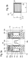
- the axial length of the thread-guiding section of the bushing 120 is substantially equal to the engagement length L.
- the length of the bushing in the axial direction is approximately equal to the engagement length L.
- the actuator 30a extends in the axial direction R at a passage 107 through the gear housing 52a, and also through an outer housing of the power tool 14a.
- the sealing element 72a in particular an O-ring element, is provided to seal the passage 107, in particular to prevent lubricant from escaping there.
- a cover element 109 is provided, which supports the hollow cylinder section 105 in the axial direction relative to the gear housing 52a. The cover element 109 presses the seal 72a against the gear housing 52a or a wall section 52a' surrounding the passage.
- the hollow spindle 12a is mounted on the gear housing 52a by means of a first bearing, a needle bearing 116, and on a bearing plate element or a receiving flange 92 of the bearing plate element by means of a second bearing, here a ball bearing 117.
- the output shaft 12a extends through the bearing plate element and the receiving flange 92.
- the gear housing interior 108 is sealed by the second bearing 117 and partially sealed by the first bearing 116.
- the shaft seal 100 is a threaded shaft seal 100 provided on a bushing 120.
- the thread is screwed into the inner wall 122 of the bushing 120 as an internal thread 123. It serves to return the lubricant from the gap 110 toward the interior 108 of the gearbox housing.
- the gap 110, or the gap remaining between the bushing 120 and the actuator 30a, is lubricated by the lubricating grease entering the gap from the interior 108 of the gearbox housing.
- the return flow prevents the unwanted escape of lubricating grease; the lubricating grease is forced back by the rotation of the spindle on the outer wall of the actuator 30a toward the end face 105a and into the interior 108 of the gearbox housing.
- a sealing element in particular a sealing cap (not shown) surrounding the actuator 30a and/or the decoupling element 28a, can be provided on or in the hollow cylinder section 105, which prevents the penetration of dust into the first end 111 of the gap 110.
- the bushing 120 is pressed into the hollow cylinder section 105 so that it is connected to the hollow spindle 12a in a rotationally fixed and, in particular, axially immovable manner.
- the bushing 120 has a second end of the output spindle 12a in the area of the hollow cylinder section 105 or its end face 105a Outer flange 121. This simplifies the installation of the bushing in the hollow spindle and ensures a tight fit.
- the bushing is made of bronze.
Landscapes
- Engineering & Computer Science (AREA)
- Mechanical Engineering (AREA)
- Constituent Portions Of Griding Lathes, Driving, Sensing And Control (AREA)
- Transmission Devices (AREA)
Claims (12)
- Outil électrique (14a), en particulier outil électrique portatif,comprenant un moteur d'entraînement (58a) reçu dans un boîtier (52a, 56a) pour entraîner un arbre d'entraînement (60),comprenant un carter de transmission (52a) pour la réception d'une unité de transmission (54a), en particulier un engrenage conique, pour la conversion de la rotation de l'arbre d'entraînement (60) en une rotation d'un arbre de sortie (12a) autour d'un axe de rotation (R) de l'unité de transmission,dans lequel un lubrifiant pour la lubrification de la transmission peut être reçu dans un espace intérieur de carter de transmission (108) du carter de transmission (52a),dans lequel l'arbre de sortie (12a) présente une première extrémité, sur laquelle une unité d'outil insérable (18a) peut être montée, et présente une deuxième extrémité,dans lequel l'arbre de sortie (12a) est réalisé sous la forme d'une broche creuse présentant une cavité (115), qui présente sur sa deuxième extrémité une partie cylindrique creuse (105),et dans lequel un actionneur (30a), qui s'insère dans la partie cylindrique creuse (105), est disposé de manière solidaire en rotation par rapport au carter de transmission (52a),caractérisé en ce queune fente (110) s'étendant le long de l'axe de rotation (R), qui est reliée sur sa première extrémité (111) à la cavité (115) et sur sa deuxième extrémité (112) à l'espace intérieur de carter de transmission (108), est formée entre la partie cylindrique creuse (105) et l'actionneur (30a), et queun joint d'arbre (100), qui agit à l'encontre d'une sortie de lubrifiant de la fente (110) en direction de la première extrémité (111) de l'arbre de sortie (12a), est disposé dans la fente (110).
- Outil électrique selon la revendication 1, caractérisé en ce que le joint d'arbre (100) est un joint d'arbre fileté, qui est conçu pour le retour du lubrifiant de la fente (110) en direction du carter de transmission (52a).
- Outil électrique selon la revendication 2, caractérisé en ce qu'une douille (120), qui est enfoncée en particulier dans la partie cylindrique creuse (105) sur la paroi intérieure (122) cylindrique de laquelle est réalisé un filetage femelle (123), qui forme le joint d'arbre fileté, est disposée dans la partie cylindrique creuse (105).
- Outil électrique selon la revendication 3, caractérisé en ce que la douille (120) présente une bride extérieure (121), s'appliquant à la deuxième extrémité de l'arbre de sortie (12a) sur la face frontale (105a) de la partie cylindrique creuse (105).
- Outil électrique selon la revendication 3 ou 4, caractérisé en ce que la douille (120) présente une épaisseur de paroi comprise entre 0,2 mm et 0,8 mm, de préférence entre 0,3 mm et 0,5 mm.
- Outil électrique selon la revendication 2, caractérisé en ce qu'un filetage femelle (123), qui forme le joint d'arbre fileté (100), est réalisé sur une paroi intérieure cylindrique (122) de la partie cylindrique creuse (105).
- Outil électrique selon la revendication 2, caractérisé en ce qu'un filetage mâle, qui forme le joint d'arbre fileté (100), est réalisé sur une paroi extérieure cylindrique de l'actionneur (30a).
- Outil électrique selon l'une quelconque des revendications précédentes, qui présente un dispositif de serrage rapide (10a) qui est conçu pour une fixation sans outil de l'unité d'outil insérable (18a) sur l'arbre de sortie (12a).
- Outil électrique selon la revendication 1, caractérisé en ce que l'actionneur (30a) est un élément d'actionnement (30a) du dispositif de serrage rapide.
- Outil électrique selon l'une quelconque des revendications 8 et 9, caractérisé en ce que le dispositif de serrage rapide (10a) présente au moins une unité de serrage (16a), qui pour la fixation sans outil de l'unité d'outil insérable (18a) sur l'arbre de sortie (12a) présente au moins un élément de serrage (20a, 22a) monté mobile pour une action de force de serrage sur l'unité d'outil insérable (18a) dans une position de serrage de l'élément de serrage (20a, 22a), et présente au moins une unité de commande (24a) pour la mise en œuvre d'un mouvement de l'élément de serrage (20a, 22a) dans la position de serrage et/ou dans une position de desserrage de l'élément de serrage (20a, 22a) dans laquelle l'unité d'outil insérable (18a) peut être retirée de l'unité de serrage (16a).
- Outil électrique selon la revendication 10, caractérisé en ce que le dispositif de serrage rapide présente au moins une unité de découplage (26a), qui est destinée à découpler l'unité de commande (24a) en fonction d'une vitesse de rotation de l'arbre de sortie (12a) de l'unité de serrage (16a).
- Outil électrique selon l'une quelconque des revendications précédentes, qui est réalisé sous la forme d'une meuleuse d'angle (14a).
Priority Applications (3)
| Application Number | Priority Date | Filing Date | Title |
|---|---|---|---|
| EP23159426.8A EP4424467B1 (fr) | 2023-03-01 | 2023-03-01 | Outil électrique |
| CN202410236008.1A CN118578256A (zh) | 2023-03-01 | 2024-03-01 | 电动工具 |
| US18/593,197 US12600022B2 (en) | 2023-03-01 | 2024-03-01 | Power tool |
Applications Claiming Priority (1)
| Application Number | Priority Date | Filing Date | Title |
|---|---|---|---|
| EP23159426.8A EP4424467B1 (fr) | 2023-03-01 | 2023-03-01 | Outil électrique |
Publications (3)
| Publication Number | Publication Date |
|---|---|
| EP4424467A1 EP4424467A1 (fr) | 2024-09-04 |
| EP4424467C0 EP4424467C0 (fr) | 2025-05-07 |
| EP4424467B1 true EP4424467B1 (fr) | 2025-05-07 |
Family
ID=85415117
Family Applications (1)
| Application Number | Title | Priority Date | Filing Date |
|---|---|---|---|
| EP23159426.8A Active EP4424467B1 (fr) | 2023-03-01 | 2023-03-01 | Outil électrique |
Country Status (3)
| Country | Link |
|---|---|
| US (1) | US12600022B2 (fr) |
| EP (1) | EP4424467B1 (fr) |
| CN (1) | CN118578256A (fr) |
Family Cites Families (5)
| Publication number | Priority date | Publication date | Assignee | Title |
|---|---|---|---|---|
| DE3741484C1 (de) * | 1987-12-08 | 1989-08-24 | Fein C & E | Handwerkzeugmaschine mit automatischer Arretierung der Arbeitsspindel |
| DE102004020982A1 (de) * | 2004-04-23 | 2005-11-17 | C. & E. Fein Gmbh | Kraftgetriebenes Handwerkzeug mit Spanneinrichtung für ein Werkzeug |
| US9067293B2 (en) * | 2011-09-30 | 2015-06-30 | Robert Bosch Gmbh | Accessory clamp for a power tool |
| DE102016220367A1 (de) * | 2016-10-18 | 2018-04-19 | Robert Bosch Gmbh | Schnellspannvorrichtung für eine zumindest eine rotierend antreibbare Abtriebswelle aufweisende tragbare Werkzeugmaschine, insbesondere Winkelschleifmaschine |
| DE102016220343A1 (de) | 2016-10-18 | 2018-04-19 | Robert Bosch Gmbh | Schnellspannvorrichtung für eine zumindest eine rotierend antreibbare Abtriebswelle aufweisende tragbare Werkzeugmaschine, insbesondere Winkelschleifmaschine |
-
2023
- 2023-03-01 EP EP23159426.8A patent/EP4424467B1/fr active Active
-
2024
- 2024-03-01 CN CN202410236008.1A patent/CN118578256A/zh active Pending
- 2024-03-01 US US18/593,197 patent/US12600022B2/en active Active
Also Published As
| Publication number | Publication date |
|---|---|
| US20240293923A1 (en) | 2024-09-05 |
| EP4424467A1 (fr) | 2024-09-04 |
| EP4424467C0 (fr) | 2025-05-07 |
| CN118578256A (zh) | 2024-09-03 |
| US12600022B2 (en) | 2026-04-14 |
Similar Documents
| Publication | Publication Date | Title |
|---|---|---|
| DE69522201T2 (de) | Werkzeughalter | |
| DE3241350A1 (de) | Vorrichtung zur umwandlung einer drehbewegung in eine linearbewegung | |
| EP0447408A1 (fr) | Outil manuel avec dispositif de serrage rapide a main en plusieurs parties. | |
| EP1039173A2 (fr) | Dispositif de palier pour cric à vis | |
| DE7008323U (de) | Kupplungs-bremseinheit | |
| DE2328462C2 (de) | Schlagbohrmaschine | |
| DE69011887T2 (de) | Spindelvorsatzgetriebe. | |
| EP0254850A2 (fr) | Meuleuse portative à moteur | |
| WO2012055642A1 (fr) | Dispositif de sécurité par serrage imperdable | |
| DE20119835U1 (de) | Handwerkzeugmaschine mit Spindelstop | |
| DE3013855C2 (de) | Lenkgetriebe | |
| EP2319287A1 (fr) | Agencement de liaison destiné à relier un entraînement de lame de faucheuse et une lame de faucheuse | |
| DE3305632C2 (de) | Reibungskupplungs- und Bremskombination | |
| EP0029863A1 (fr) | Instrument à main dentaire | |
| DE102011011384B4 (de) | Hand-Werkzeugmaschine mit einem Lamellenmotor aus einem Nicht-Metall | |
| CH695487A5 (de) | Werkzeugmaschine mit einem Getrieberaum mit Schmiermittel und einer Druckausgleichseinrichtung des Getrieberaums. | |
| EP0171574A2 (fr) | Porte-alésoir | |
| EP4424467A1 (fr) | Outil électrique | |
| EP1537948B1 (fr) | Outil portatif motorisé | |
| EP1053072B1 (fr) | Tete de percage ou de fraisage | |
| DE69632496T2 (de) | Spindel mit Vorrichtung zur Erhöhung der Drehzahl | |
| EP1245329A1 (fr) | Dispositif pour l'alimentation en fluide de refroidissement et de lubrification d'un outil avec courant interne pour ce fluide | |
| DE102021108443B4 (de) | Manueller Hebezug | |
| DE10145296A1 (de) | Handwerkzeugmaschine mit einer Druckausgleichseinrichtung | |
| DE102007038971A1 (de) | Maschinenelement für eine Welle-Nabe-Verbindung und Herstellungsverfahren für eine Welle-Nabe-Verbindung |
Legal Events
| Date | Code | Title | Description |
|---|---|---|---|
| PUAI | Public reference made under article 153(3) epc to a published international application that has entered the european phase |
Free format text: ORIGINAL CODE: 0009012 |
|
| STAA | Information on the status of an ep patent application or granted ep patent |
Free format text: STATUS: THE APPLICATION HAS BEEN PUBLISHED |
|
| AK | Designated contracting states |
Kind code of ref document: A1 Designated state(s): AL AT BE BG CH CY CZ DE DK EE ES FI FR GB GR HR HU IE IS IT LI LT LU LV MC ME MK MT NL NO PL PT RO RS SE SI SK SM TR |
|
| STAA | Information on the status of an ep patent application or granted ep patent |
Free format text: STATUS: REQUEST FOR EXAMINATION WAS MADE |
|
| 17P | Request for examination filed |
Effective date: 20241010 |
|
| P01 | Opt-out of the competence of the unified patent court (upc) registered |
Free format text: CASE NUMBER: APP_52678/2024 Effective date: 20240919 |
|
| RBV | Designated contracting states (corrected) |
Designated state(s): AL AT BE BG CH CY CZ DE DK EE ES FI FR GB GR HR HU IE IS IT LI LT LU LV MC ME MK MT NL NO PL PT RO RS SE SI SK SM TR |
|
| GRAP | Despatch of communication of intention to grant a patent |
Free format text: ORIGINAL CODE: EPIDOSNIGR1 |
|
| STAA | Information on the status of an ep patent application or granted ep patent |
Free format text: STATUS: GRANT OF PATENT IS INTENDED |
|
| INTG | Intention to grant announced |
Effective date: 20250211 |
|
| GRAS | Grant fee paid |
Free format text: ORIGINAL CODE: EPIDOSNIGR3 |
|
| GRAA | (expected) grant |
Free format text: ORIGINAL CODE: 0009210 |
|
| STAA | Information on the status of an ep patent application or granted ep patent |
Free format text: STATUS: THE PATENT HAS BEEN GRANTED |
|
| AK | Designated contracting states |
Kind code of ref document: B1 Designated state(s): AL AT BE BG CH CY CZ DE DK EE ES FI FR GB GR HR HU IE IS IT LI LT LU LV MC ME MK MT NL NO PL PT RO RS SE SI SK SM TR |
|
| REG | Reference to a national code |
Ref country code: GB Ref legal event code: FG4D Free format text: NOT ENGLISH |
|
| REG | Reference to a national code |
Ref country code: CH Ref legal event code: EP |
|
| REG | Reference to a national code |
Ref country code: IE Ref legal event code: FG4D Free format text: LANGUAGE OF EP DOCUMENT: GERMAN |
|
| REG | Reference to a national code |
Ref country code: DE Ref legal event code: R096 Ref document number: 502023000927 Country of ref document: DE |
|
| U01 | Request for unitary effect filed |
Effective date: 20250521 |
|
| P04 | Withdrawal of opt-out of the competence of the unified patent court (upc) registered |
Free format text: CASE NUMBER: APP_24856/2025 Effective date: 20250524 |
|
| U07 | Unitary effect registered |
Designated state(s): AT BE BG DE DK EE FI FR IT LT LU LV MT NL PT RO SE SI Effective date: 20250528 |
|
| PG25 | Lapsed in a contracting state [announced via postgrant information from national office to epo] |
Ref country code: ES Free format text: LAPSE BECAUSE OF FAILURE TO SUBMIT A TRANSLATION OF THE DESCRIPTION OR TO PAY THE FEE WITHIN THE PRESCRIBED TIME-LIMIT Effective date: 20250507 |
|
| PG25 | Lapsed in a contracting state [announced via postgrant information from national office to epo] |
Ref country code: NO Free format text: LAPSE BECAUSE OF FAILURE TO SUBMIT A TRANSLATION OF THE DESCRIPTION OR TO PAY THE FEE WITHIN THE PRESCRIBED TIME-LIMIT Effective date: 20250807 Ref country code: GR Free format text: LAPSE BECAUSE OF FAILURE TO SUBMIT A TRANSLATION OF THE DESCRIPTION OR TO PAY THE FEE WITHIN THE PRESCRIBED TIME-LIMIT Effective date: 20250808 |
|
| PG25 | Lapsed in a contracting state [announced via postgrant information from national office to epo] |
Ref country code: PL Free format text: LAPSE BECAUSE OF FAILURE TO SUBMIT A TRANSLATION OF THE DESCRIPTION OR TO PAY THE FEE WITHIN THE PRESCRIBED TIME-LIMIT Effective date: 20250507 |
|
| PG25 | Lapsed in a contracting state [announced via postgrant information from national office to epo] |
Ref country code: HR Free format text: LAPSE BECAUSE OF FAILURE TO SUBMIT A TRANSLATION OF THE DESCRIPTION OR TO PAY THE FEE WITHIN THE PRESCRIBED TIME-LIMIT Effective date: 20250507 |
|
| PG25 | Lapsed in a contracting state [announced via postgrant information from national office to epo] |
Ref country code: RS Free format text: LAPSE BECAUSE OF FAILURE TO SUBMIT A TRANSLATION OF THE DESCRIPTION OR TO PAY THE FEE WITHIN THE PRESCRIBED TIME-LIMIT Effective date: 20250807 |
|
| PG25 | Lapsed in a contracting state [announced via postgrant information from national office to epo] |
Ref country code: IS Free format text: LAPSE BECAUSE OF FAILURE TO SUBMIT A TRANSLATION OF THE DESCRIPTION OR TO PAY THE FEE WITHIN THE PRESCRIBED TIME-LIMIT Effective date: 20250907 |
|
| PG25 | Lapsed in a contracting state [announced via postgrant information from national office to epo] |
Ref country code: SM Free format text: LAPSE BECAUSE OF FAILURE TO SUBMIT A TRANSLATION OF THE DESCRIPTION OR TO PAY THE FEE WITHIN THE PRESCRIBED TIME-LIMIT Effective date: 20250507 |
|
| PG25 | Lapsed in a contracting state [announced via postgrant information from national office to epo] |
Ref country code: CZ Free format text: LAPSE BECAUSE OF FAILURE TO SUBMIT A TRANSLATION OF THE DESCRIPTION OR TO PAY THE FEE WITHIN THE PRESCRIBED TIME-LIMIT Effective date: 20250507 |
|
| PG25 | Lapsed in a contracting state [announced via postgrant information from national office to epo] |
Ref country code: SK Free format text: LAPSE BECAUSE OF FAILURE TO SUBMIT A TRANSLATION OF THE DESCRIPTION OR TO PAY THE FEE WITHIN THE PRESCRIBED TIME-LIMIT Effective date: 20250507 |
|
| PLBE | No opposition filed within time limit |
Free format text: ORIGINAL CODE: 0009261 |
|
| STAA | Information on the status of an ep patent application or granted ep patent |
Free format text: STATUS: NO OPPOSITION FILED WITHIN TIME LIMIT |
|
| REG | Reference to a national code |
Ref country code: CH Ref legal event code: L10 Free format text: ST27 STATUS EVENT CODE: U-0-0-L10-L00 (AS PROVIDED BY THE NATIONAL OFFICE) Effective date: 20260318 |
|
| 26N | No opposition filed |
Effective date: 20260210 |
|
| U20 | Renewal fee for the european patent with unitary effect paid |
Year of fee payment: 4 Effective date: 20260327 |